Abstract
In order to solve the problem that the position synchronous performance of dual permanent magnet synchronous motor servo system is easily affected by parameter perturbation and load disturbance, an anti-disturbance integrated position synchronous control strategy of dual permanent magnet synchronous motor system is proposed. Firstly, the integral mathematical model of a dual permanent magnet synchronous motor system is established. After that, the third-order linear extended state observer is constructed to observe and compensate for disturbance in order to improve the anti-disturbance performance of the position loop. At the same time, a cross-coupled position synchronous compensator is added to improve the synchronous performance of the system, and through the Bode diagram analysis method in the frequency domain, the system stability and anti-disturbance performance are researched. Finally, the effectiveness of the proposed algorithm is verified by experimental research.
1. Introduction
Position synchronous control of the multi-motor servo system has broad application prospects in the manufacturing field, such as robotic arms, lithography machines, lidars, etc. When a motor is disturbed, it will destroy the original synergy, resulting in large synchronous errors and even causing dangerous accidents [1]. Therefore, improving the synchronous control accuracy and anti-disturbance performance of the multi-motor system is of great significance.
Multi-motor synchronous control mainly includes parallel control [2], master–slave control [3], cross-coupled control [4], virtual master axis control [5], deviation coupling control [6], etc. In the first two methods, there is no coupling effect between motors, and the synchronous performance is improved mainly by reducing the tracking error of each motor, so the synchronous performance is poor. In the last three methods, the coupling effect between the two motors is enhanced by the synchronous error compensator, so the synchronous performance is improved to a certain extent.
In terms of control strategy, the typical PID three-loop control structure was initially used to realize the position control of the motor, that is, the typical position loop-speed loop-current loop and the adjustment of PI parameters referred to in refs. [7,8]. With the development of power electronics and microprocessors, advanced control algorithms were gradually applied. In order to realize the position synchronous control of the multi-motor system, ref. [9] adopted the method of organically integrating the adaptive control and the cross-coupling control with each other. In ref. [10], a fuzzy neural network was used for position synchronous control of the dual linear motors, and the complementary sliding mode following the controller was combined to improve synchronous accuracy. Ref. [11] organically integrated H∞ control and cross-coupling control and proposed a robust position synchronous control strategy. In ref. [12], a multi-motor synchronous control method of cross-coupled second-order discrete-time fractional sliding mode control was proposed to reduce the incoordination between the linear drive motors. The above control methods rely mostly on the model of the control object, but there are often uncertain disturbances in the actual multi-motor synchronous control system, which may affect the control effect.
The unknown and uncertain part of the system can be accurately estimated by the disturbance observer and compensated to the control system to improve the control performance of the system. Ref. [13] proposed a fractional-order chaotic PMSM tracking control based on an adaptive neural network observer. Ref. [14] proposed PMSM complementary sliding mode speed control based on a sliding mode observer. The Extended State Observer (ESO) is an important part of the Active Disturbance Rejection Control (ADRC) technology proposed by Professor Jingqing Han, combining modern control theory and classical control theory. Although the nonlinear ESO has the advantages of high precision and high efficiency [15], there were some difficulties in theoretical analysis and engineering design due to the large number of parameters that need to be tuned. In ref. [16], the concept of bandwidth was introduced to convert it into the Linear Extended State Observer (LESO), greatly reducing the number of design parameters. Refs. [17,18] overcame the shortcomings of ADRC mainly derived from simulation and lack of theoretical analysis and provided a rigorous analysis of the properties of LESO observation errors, such as convergence, boundedness, and stability. Ref. [19] systematically analyzed the convergence conditions of PMSM LESO parameters and discussed in detail the influence of parameter selection on the rapidity of convergence, the suppression ability of system input interference, and the measurement noise based on the frequency domain analysis theory. Ref. [20] proposed a PMSM position servo system based on an active disturbance rejection controller to solve the influence of parameter changes and external disturbances on system positioning. Ref. [21] proposed the integrated control method of position and speed based on active disturbance rejection control and adopted the deviation feedback algorithm to limit the speed amplitude and suppress jitter. The above literature apply the linear expansion state observer in single motor control.
At present, the method has also been initially applied in the field of multi-motor speed synchronous control. In ref. [22], the circular coupling structure of current compensation was adopted, and an active disturbance rejection compensator was designed to reduce the synchronous error. Ref. [23] proposed a new control strategy combining a self-correcting speed compensator and improved the active disturbance rejection controller in order to solve problems such as lag and weak anti-disturbance ability existing in the practical application of multi-motor collaborative control system. Ref. [24] proposed an anti-disturbance speed synchronous control strategy based on unified modeling of dual motor speed loops and used a linear active disturbance rejection controller to estimate and compensate for the disturbances caused by load mutation and model mismatch. However, the abovementioned literature describes the application of ADRC in speed synchronous control, and the influence of load disturbance on position synchronous is not considered.
In the servo control system, the load disturbance and motor parameters fluctuation not only exert influence on speed synchronous control but also affect the positioning accuracy, and generate a greater synchronous error. Therefore, in order to reduce the synchronous error and improve the anti-disturbance performance of the system, this paper proposes an integrated position synchronous control strategy for the dual permanent magnet synchronous motor system based on active disturbance rejection. Firstly, the mathematical model of a dual permanent magnet synchronous motor system is established, and then the disturbance is estimated and compensated by a linear extended state observer to improve the anti-disturbance performance of the position loop. At the same time, the cross-coupled position synchronous compensator is added to improve the synchronous performance of the system, and the stability and anti-disturbance performance of the system are studied using the Bode diagram analysis method in the frequency domain. Meanwhile, the improvement of the synchronous performance of the system is theoretically deduced.
2. System Model
The object of this paper is the surface mount permanent magnet synchronous motor, whose motion equation can be expressed as
where θ is the rotor position angle, ω is the mechanical angular velocity, J is the moment of inertia, Kt is the torque constant, iq is the q-axis current, TL is the load torque, and B is the viscous friction coefficient.
The current loop adopts id* = 0 as the control mode, which can be seen from Equations (1) and (2),
In PMSM servo control, the disturbances such as load variation and motor parameters perturbation not only affect the performance of the servo speed loop but also affect the position loop to a certain extent. To solve this problem, b = Kt/J is the control quantity, u = iq* is the given value of q-axis current, and the disturbance term is γ(t); then, Equation (3) can be transformed into
where γ(t) is the total disturbance term, including q-axis current tracking error, load torque, and viscous friction, and γ(t) = −Kt(iq* − iq)/J − TL/J − Bω/J.
When x1 = θ, x2 = ω, x3 = γ(t),
Equation (5) is written in matrix form, which is
where , x = [x1 x2 x3]T, , , .
Thus, the state equation of the dual permanent magnet synchronous motor can be obtained as
where X = [xTm1 xTm2]T = [x1 x2 x3 x4 x5 x6]T = [θ1 ω1 γ1 θ2 ω2 γ2]T, , , , , .
3. Traditional P-PI-PI Control Strategy
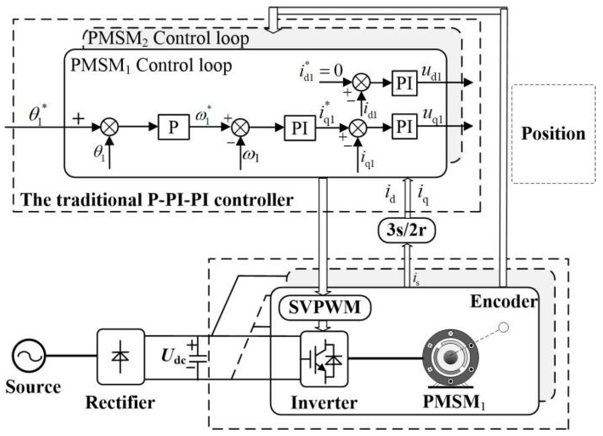
In the traditional P-PI-PI three-loop control structure, where the position loop adopts P control, which is represented by kpp, the speed loop adopts PI control, in which kpv and kiv represent proportional and integral gain, respectively, and the current loop adopts PI control, in which kpi and kii represent proportional and integral gain, respectively. The selection of three-loop PI parameters is based on the frequency domain method, referring to refs. [7,8]. Figure 1 shows the structure diagram of the traditional P-PI-PI three-loop control.
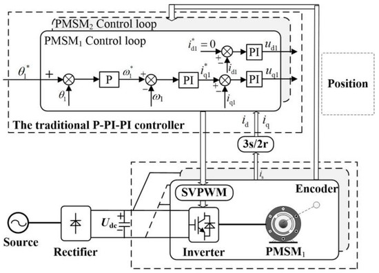
Figure 1.
The structure diagram of the traditional P-PI-PI three-loop control.
4. Position Synchronous Control and Performance Analysis of Dual Permanent Magnet Synchronous Motor System
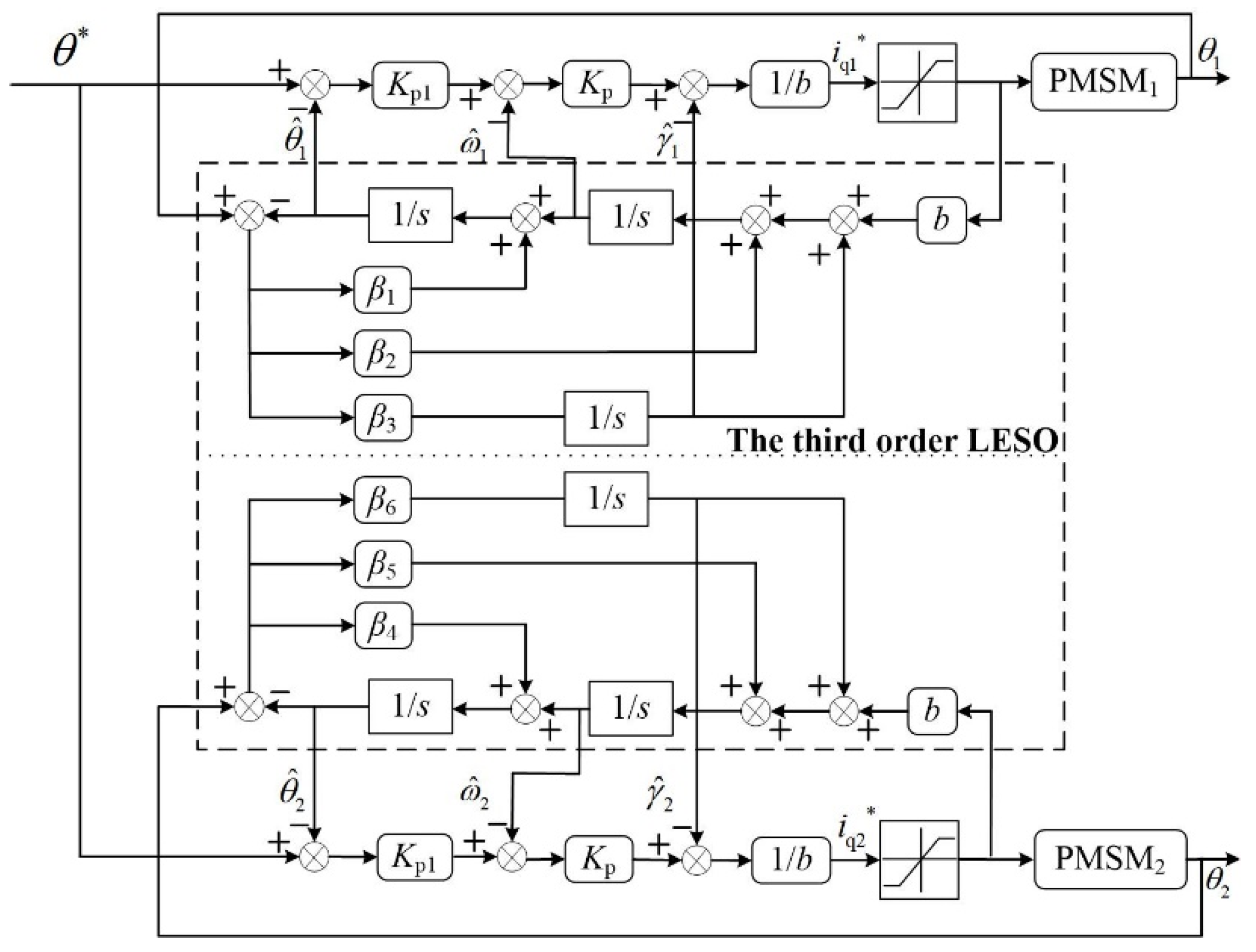
4.1. State Observer Construction
The liner extended state observer (LESO) is constructed as
where is the gain of the observer, and Z = [z1 z2 z3 z4 z5 z6]T, z1 z2 z3 z4 z5 z6 are the observed values of the corresponding state variables, namely .
Based on the idea of ref. [24], the linear error feedback control rate of dual motors is designed as
In the formula, Kp1 is the proportional coefficient of position adjustment, Kp is the proportional coefficient of speed adjustment, and θ* is the given rotor position.
To sum up, the structure diagram of linear active disturbance rejection controller of dual permanent magnet synchronous motor system can be obtained as shown in Figure 2.

Figure 2.
Structure diagram of linear active disturbance rejection controller for dual permanent magnet synchronous motor system.
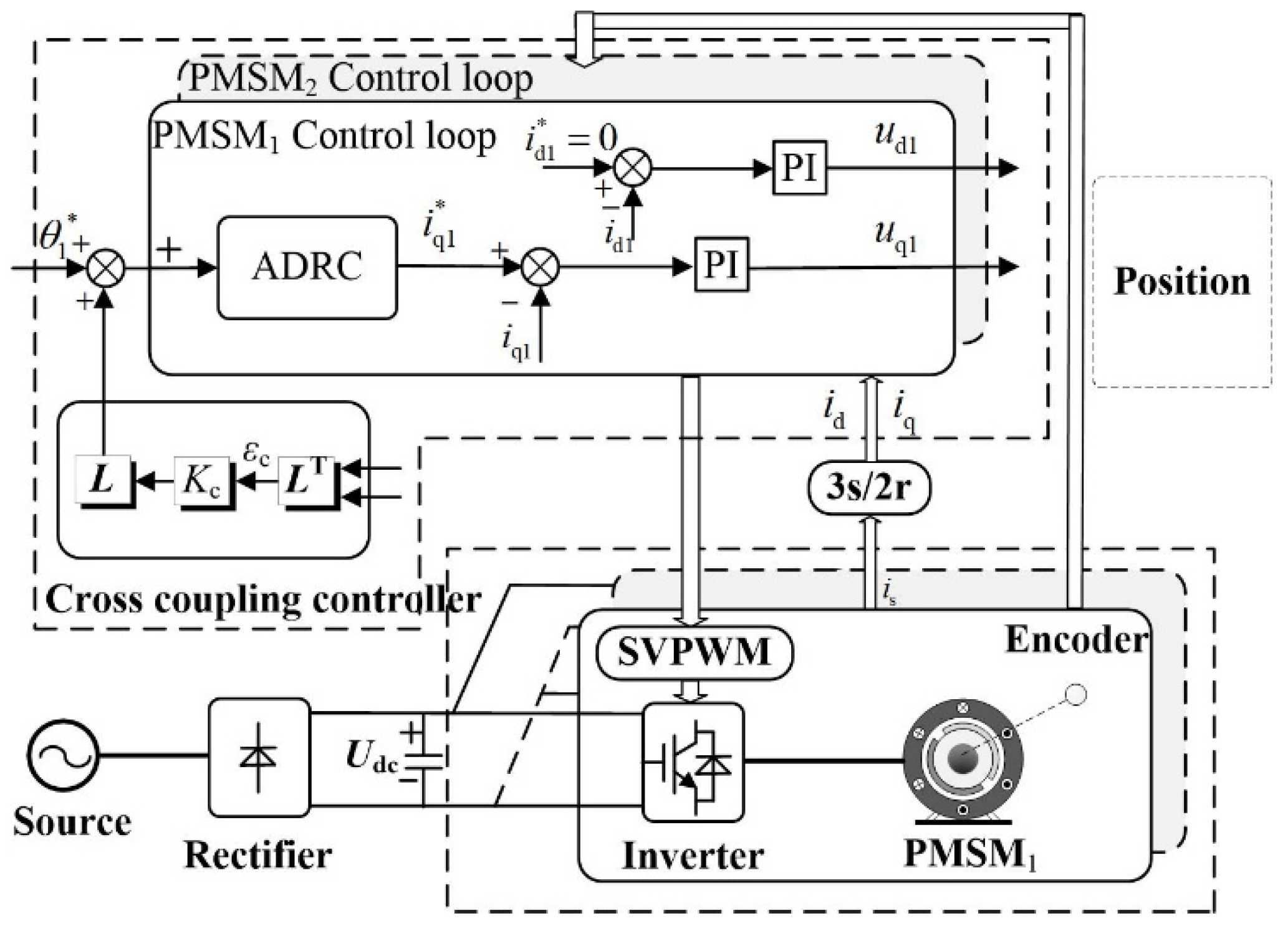
4.2. Design of Position Synchronous Controller
In order to improve the synchronous performance of the dual permanent magnet synchronous motor system, a cross-coupled position synchronous compensator is added, as shown in Figure 3. In the figure, Kc is the proportional coefficient of the cross-coupled position synchronous compensator. εc is the position synchronous error.
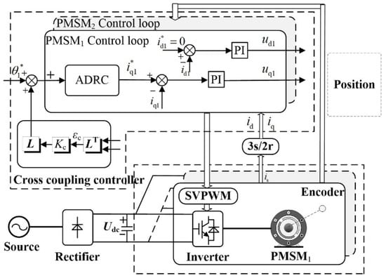
Figure 3.
Structure diagram of position synchronous control system of dual permanent magnet synchronous motor.
4.3. System Parameter Selection
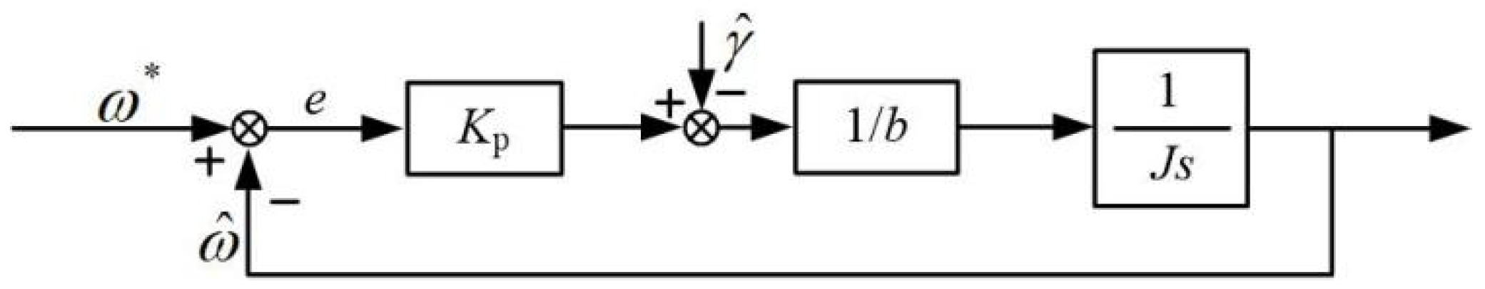
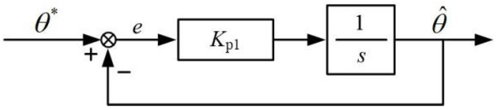
The selection of Kp and Kp1 and Kp1 and Kp are used to reflect the response speed for the position loop and speed loop of the system. The larger Kp1 and Kp are, the faster the dynamic response speed will be. However, if Kp1 and Kp are too large, the stability of the system will be affected. Figure 4 and Figure 5 are the equivalent structure diagrams of the speed loop and the position loop. The selection methods of Kp and Kp1 are based on the frequency domain method, as shown below.
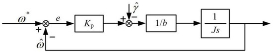
Figure 4.
The equivalent block diagram of speed loop.
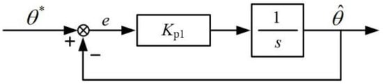
Figure 5.
The equivalent block diagram of position loop.
Figure 4 is the equivalent block diagram of the speed loop.
In order to simplify the operation, the inner current loop Gco(s) with higher bandwidth is represented by 1. The open-loop transfer function of the speed loop Gso(s) can be represented as , setting ωsc as the open-loop cutoff frequency of the speed loop, and the phase margin equations of the speed loop can be determined as
Then, Kp can be calculated as .
Figure 5 is the equivalent block diagram of the position loop.
In order to simplify the operation, the inner loop Gsc(s) with higher bandwidth is represented by 1. The open-loop transfer function of the position loop Gpo(s) can be represented as , setting ωpc as the open-loop cutoff frequency of the position loop, and the phase margin equations of the position loop can be determined as
Then, Kp1 can be calculated as .
The selection of Kc: The function of the coupled coefficient is to magnify the difference between the position of the two motors. Its value is positively correlated with the synchronous performance, but of the value is too large, it will cause system speed oscillation or even instability.
The selection of L: The observer gain of LESO depends on the closed-loop pole or bandwidth of the observer, which determines the observation speed and observation accuracy of the observer. In order to ensure fast observation speed, observation accuracy, and simplicity, the six pole positions of the observer are all −θob, so the ideal characteristic equation of the observer can be obtained as
It can also be obtained that
4.4. Anti-Disturbance Performance Analysis
In order to analyze the anti-disturbance performance of the system, the Bode diagram analysis method is adopted in the frequency domain. Firstly, the information on motor 1 in Formula (8) is expanded, and then
Equation (14) is applied with the Laplace transform, and it can be obtained that
The information of motor 1 is proposed in Equation (9), and when the Laplace transform is used, it can be obtained that
Substitute Equation (15) into Equation (16) and simplify it; then, it can be obtained that
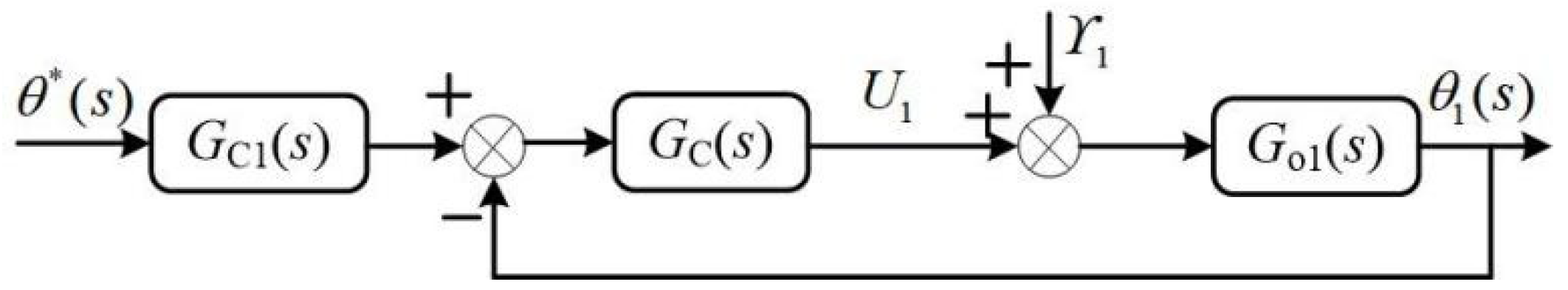
Equation (17) is drawn as the equivalent transfer function, which is shown in Figure 6.
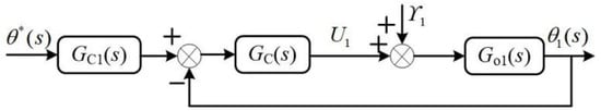
Figure 6.
Block diagram of equivalent transfer function.
In the figure, GC1(s) and GC(s) are
Combined with Go1(s), the open-loop transfer function can be obtained as
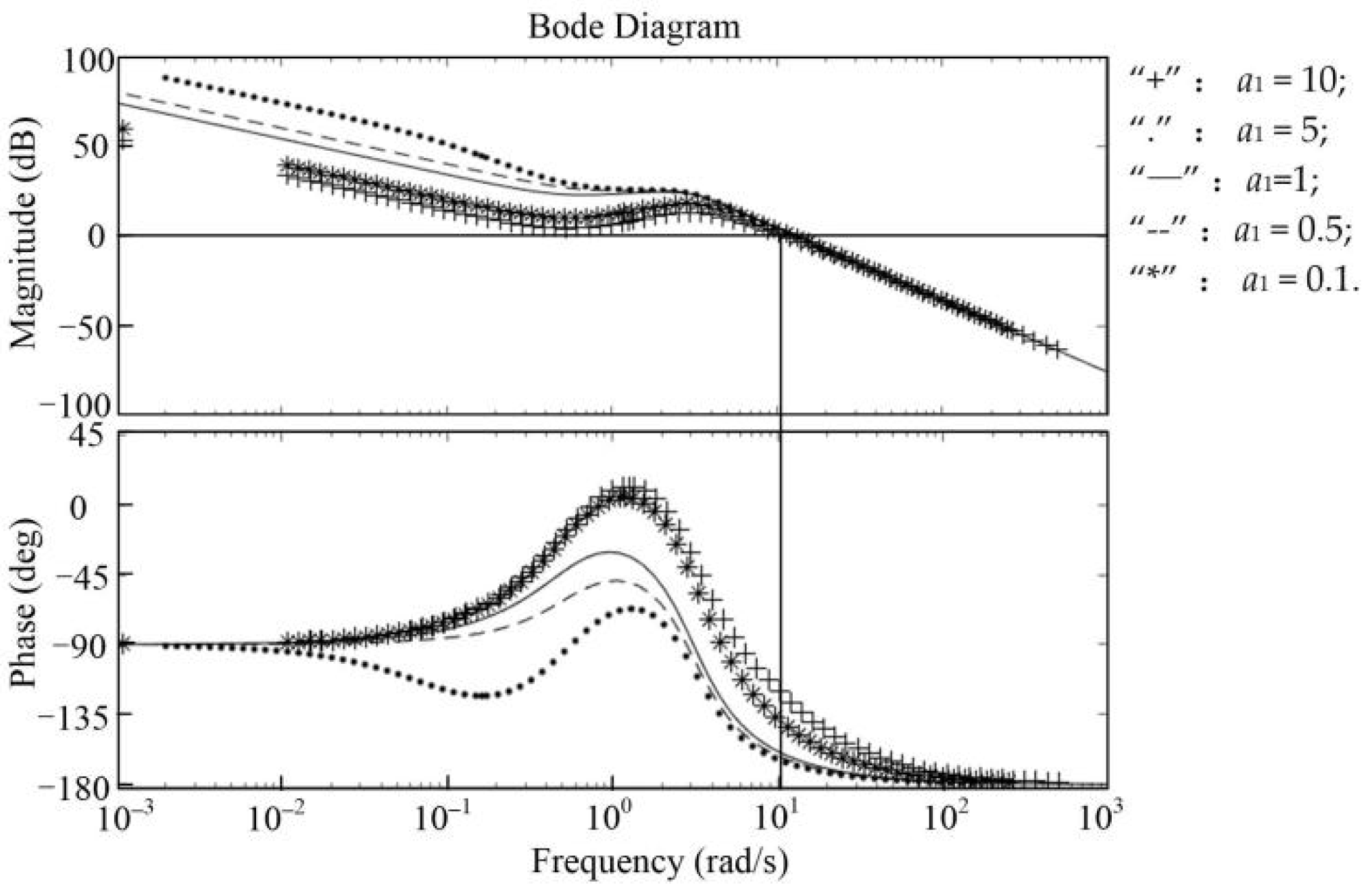
To analyze the anti-disturbance performance of the system, the influence of internal disturbance on the system is analyzed. As can be seen from Equation (19), the parameter changes can be reflected by the changes of a1, so when a1 changes and the Bode diagram of the open-loop transfer function is drawn, “+” corresponds to a1 = 10, “.” corresponds to a1 = 5, the straight line corresponds to a1=1, “--” corresponds to a1 = 0.5, and “*” corresponds to a1 = 0.1.
It can be seen from Figure 7 that the phase angle margin and crossing frequency of the system are not significantly affected by the change of a1, indicating that the controller has a good suppression effect on the internal disturbance.
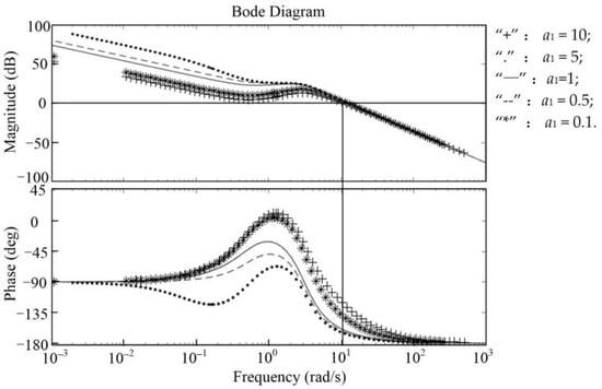
Figure 7.
Bode diagram of open loop transfer function when a1 changes.
Then, the influence of external disturbance on the system is analyzed, and the transfer function of external disturbance to the system output is obtained as
The anti-external disturbance performance of the system is analyzed when b and a1 change. First, let b remain unchanged. When a1 changes, draw the Bode diagram of the transfer function. “+” corresponds to a1 = 10, “.” corresponds to a1 = 5, the straight line corresponds to a1 = 1, “--” corresponds to a1 = 0.5, and “*” corresponds to a1 = 0.1.
It can be seen from Figure 8 that the system is almost unaffected by changes in a1, indicating that the controller has a good inhibitory effect on external disturbances.
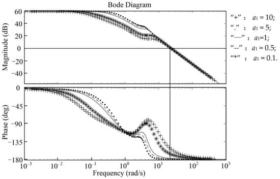
Figure 8.
Bode diagram of the external disturbance to the system output transfer function when a1 changes.
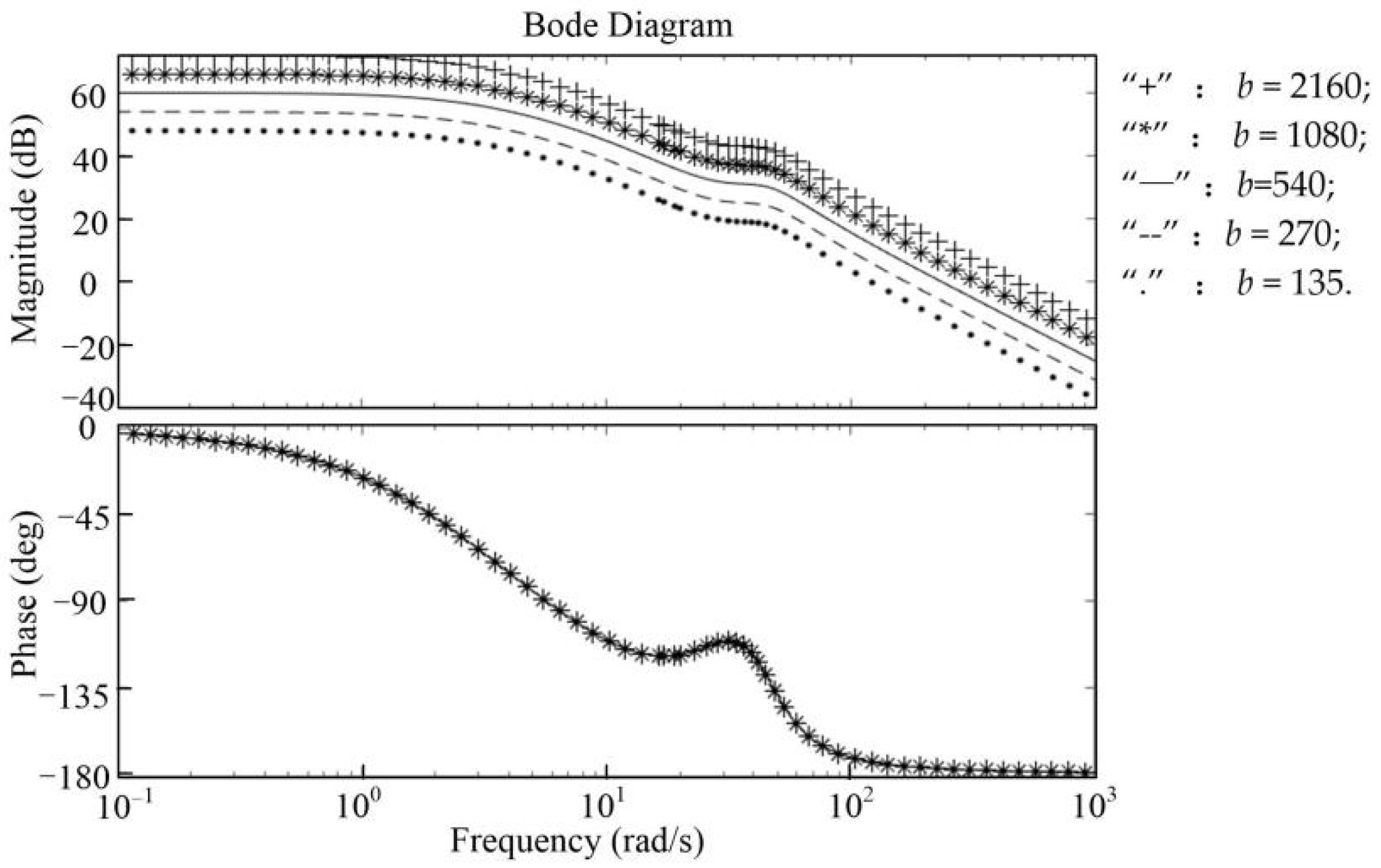
When a1 remains unchanged and b changes, the transfer function Bode diagram is drawn to analyze the anti-disturbance performance of the system. “+” corresponds to b = 2160, “*” corresponds to b = 1080, the straight line corresponds to b = 540, “--” corresponds to b = 270, and “.” corresponds to b = 135.
It can be seen from Figure 9 that when b changes, the system characteristics will be affected, and the stability margin will be reduced to a certain degree.
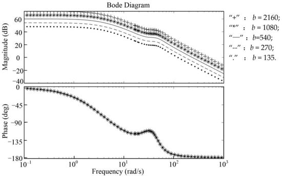
Figure 9.
Bode diagram of the external disturbance to the system output transfer function when b changes.
4.5. Synchronous Performance Analysis
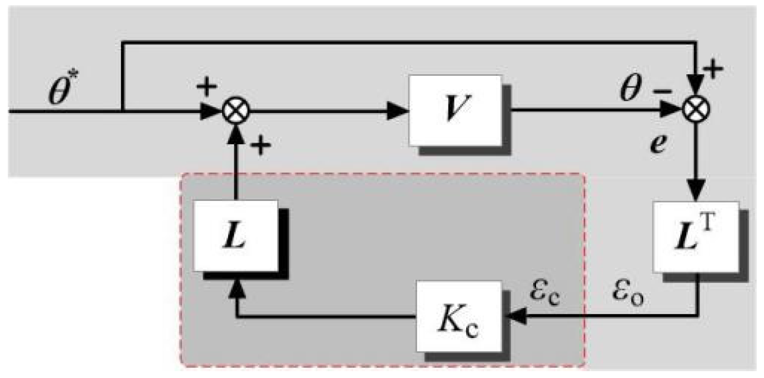
In order to analyze the synchronous performance of the system in which the cross-coupled position synchronous compensator is added, the position loop, speed loop, and current loop controllers of the two motors are represented by V. Then, the principle diagram of the cross-coupled position synchronous compensator is shown in Figure 10, where θ* = [θ1* θ2*]T; θ = [θ1 θ2]T; e = [e1 e2]T; V = diag (V1, V2); L = [−1 1]T; e1, e2 are the position tracking errors of the first motor and the second motor, respectively. The light gray part represents the uncoupled structure, and εo is the synchronous error in the uncoupled structure. The light gray + dark gray part represents the cross-coupled structure, and εc is the synchronous error in the cross-coupled structure.
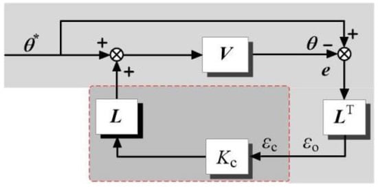
Figure 10.
Schematic diagram of cross-coupled position synchronous compensator.
In the uncoupled structure, the expression of synchronous error is
In the cross-coupled structure, the expression of synchronous error is
Introduce the lemma of matrix inverse, and it can be obtained as
Through the transformation of Equations (21)–(23), it can be obtained as
where P = LTVL.
It can be seen from Equation (24) that by adding the cross-coupled position synchronous compensator, the synchronous error εc will decrease relative to εo in the case of uncoupled structure, and the reduction degree depends on the adjustment of the coupling coefficient.
5. Experiment Validation
5.1. Experimental System
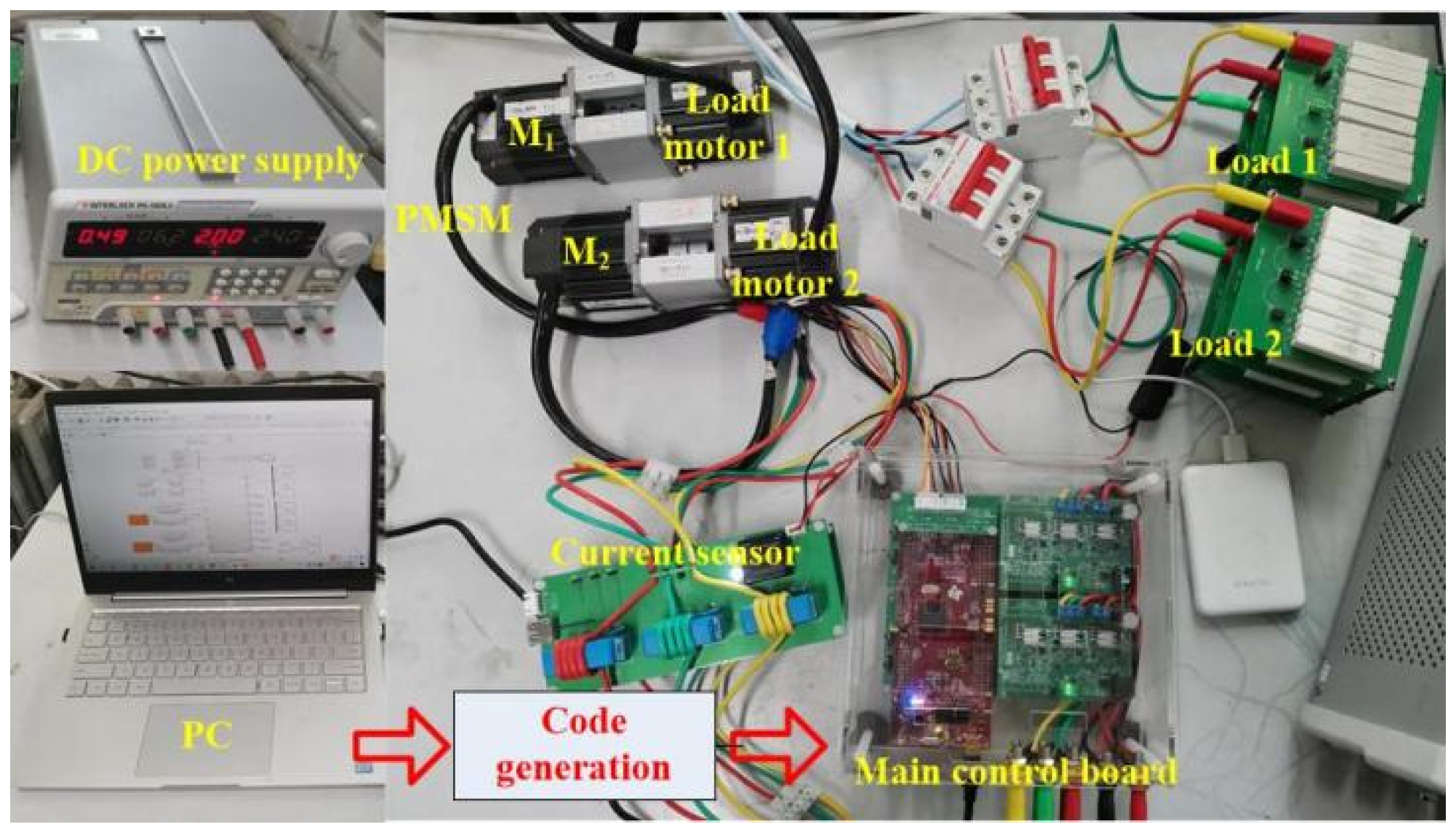
In order to verify the correctness and feasibility of the proposed control strategy, the experimental platform of the dual permanent magnet synchronous motor position synchronous control system is built in this paper, as shown in Figure 11. The experimental system includes two permanent magnet synchronous motors, two load motors, a main control circuit, a drive circuit, a current sensor, etc. The main control chip adopts TI’s DSP chip TMS320F28379D, combined with dual main core + dual co-processor architecture. The control period is 100 μs. The parameters of the PMSM-driven servo system and controller are shown in Table 1.

Figure 11.
Dual PMSM system experimental platform.

Table 1.
The parameters of PMSM-driven servo system and controller.
5.2. Tracking Performance and Synchronization Performance Verification
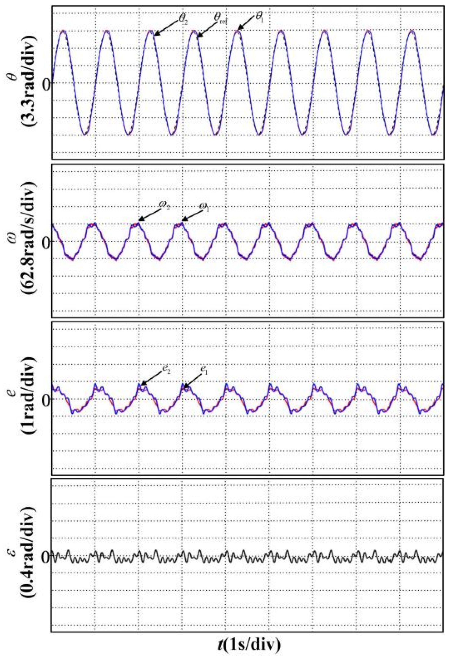
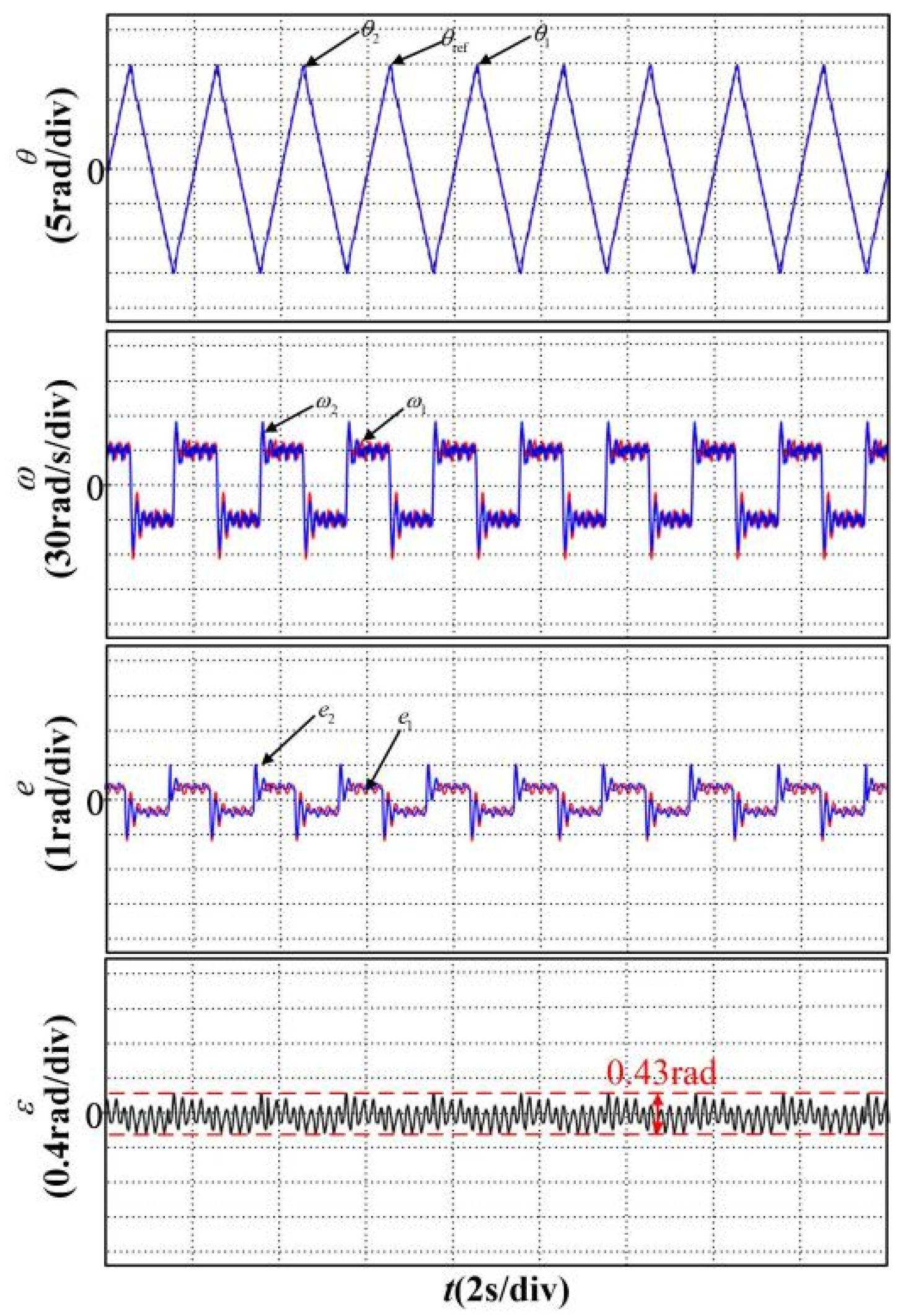
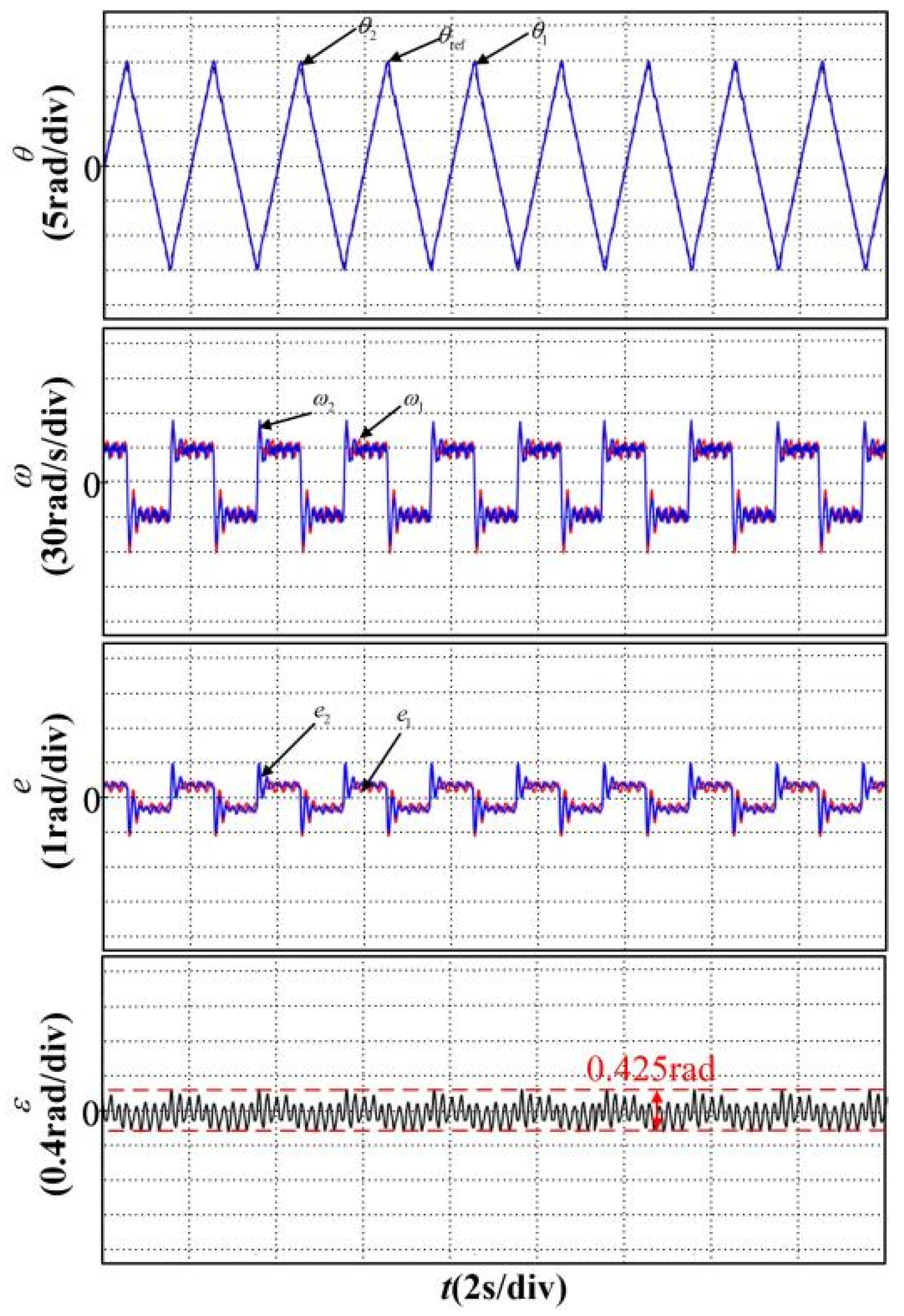
In order to verify the tracking performance and synchronous performance of the proposed ADRC position synchronous control strategy for a dual permanent magnet synchronous motor system, when tracking the broken line signal and the sinusoidal signal, respectively, the position, speed, tracking error, and the synchronous error waveforms are shown in Figure 12 and Figure 13. The black dotted line in the figure represents the given position, the solid red line represents the response waveform of motor 1, and the solid blue line represents the response waveform of motor 2.
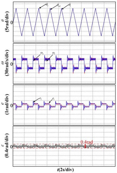
Figure 12.
Motor responses when tracking polyline signal.
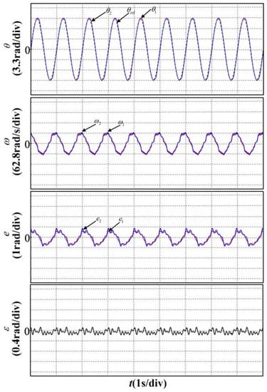
Figure 13.
Motor responses when tracking sinusoidal signal.
5.3. Anti-Disturbance Performance Verification
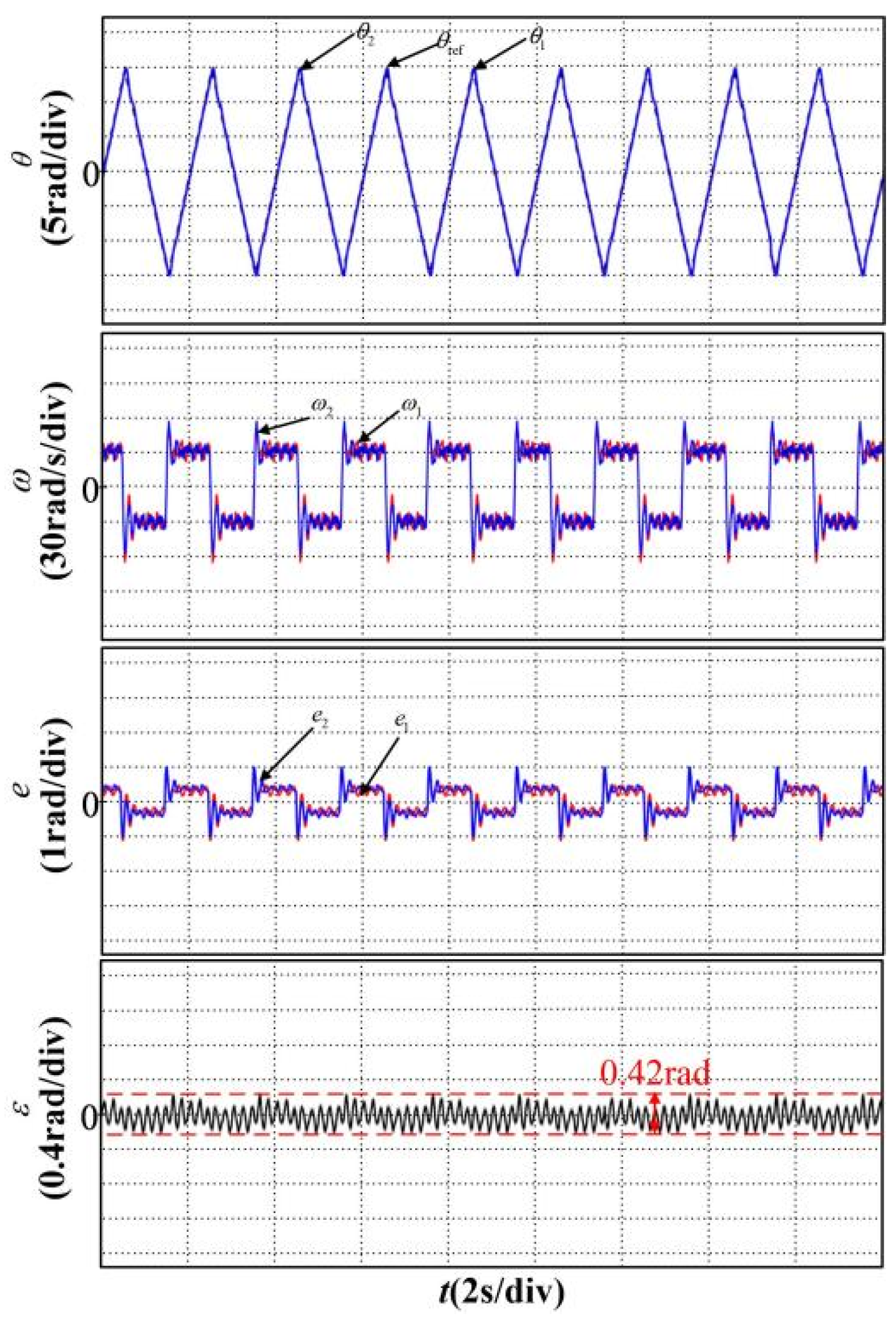
In order to verify the anti-disturbance performance of the proposed control strategy under the mismatch of motor parameters, the experiment is carried out when the resistance R, the inductance L, and the inertia J deviate from the nominal value by 150%, and the position, speed, tracking error, and synchronous error signals are collected when tracking the broken line signal, such as in Figure 14, Figure 15 and Figure 16.
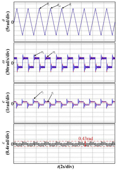
Figure 14.
Motor responses when R changes.
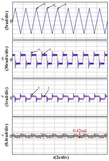
Figure 15.
Motor responses when L changes.

Figure 16.
Motor responses when J changes.
It can be seen from Figure 14, Figure 15 and Figure 16 that the synchronous error varies very little, and the system performance does not change significantly, indicating that the proposed ADRC algorithm has good anti-disturbance performance against the change of internal parameters.
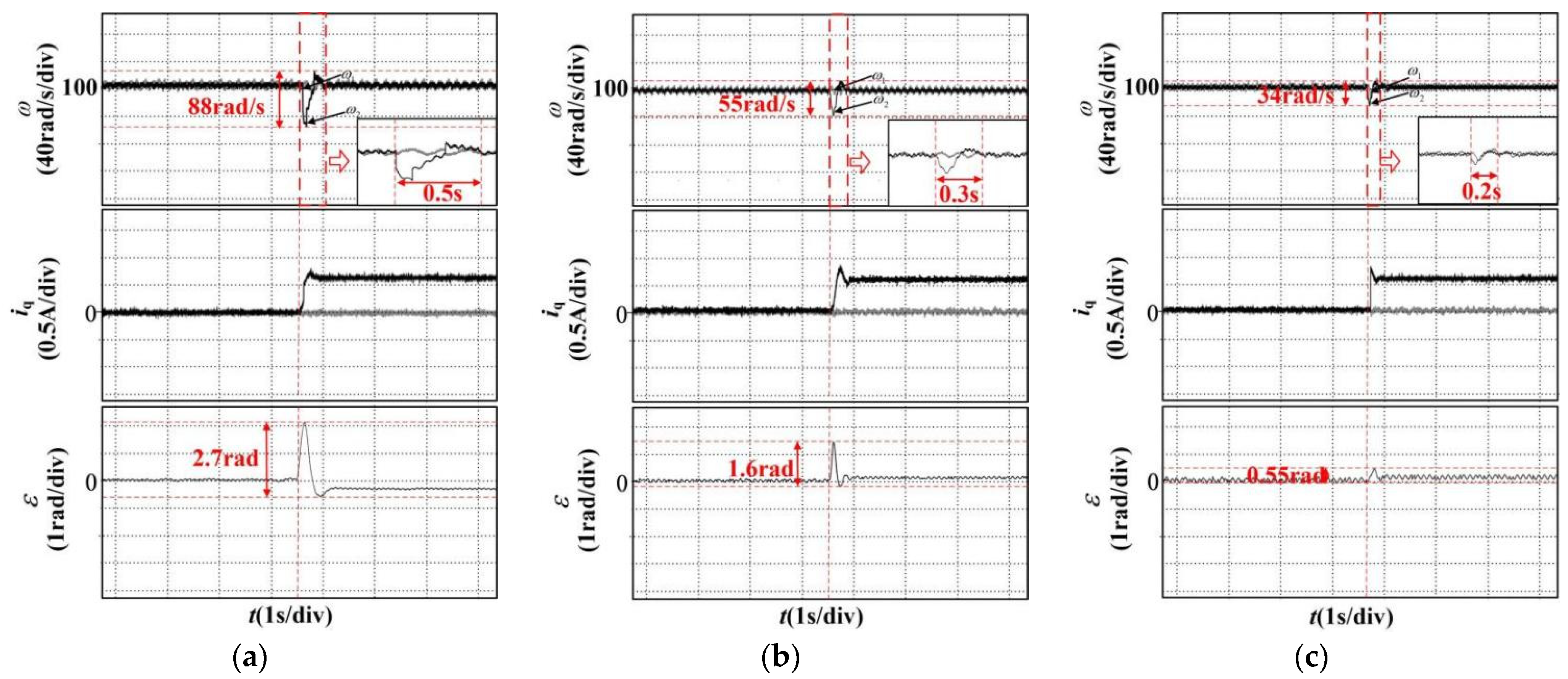
In order to verify the anti-disturbance performance of the proposed control strategy under external disturbance, the dual-motor system is made to track the slope position signal, and a sudden constant load is applied to the second motor while the first motor is not loaded. The traditional P-PI-PI control strategy, ADRC control strategy without-coupling (Kc = 0), and cross-coupling (Kc = 0.5) are used, respectively. The speed, q-axis current, and synchronous error comparison waveform are shown in Figure 17. The gray and black lines in the figure represent the responses of motors 1 and 2, respectively. At the same time, the comparison results are summarized, as shown in Table 2.
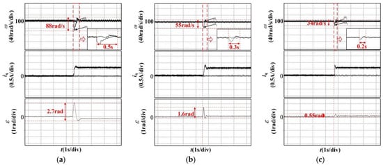
Figure 17.
Motor responses when loaded, (a) The traditional P-PI-PI control, (b) Kc = 0, (c) Kc = 0.5.
Table 2.
Compared results.
It can be seen from the comparison of Table 2 that when a load is applied to the second motor and the ADRC strategy is adopted, the speed dynamic response will be faster, and the synchronous error will be reduced compared with the traditional control strategy. It can be seen from the comparison of Table 2 that the load disturbance of the second motor will not reflect the first motor in the case of no coupling (Kc = 0), and the speed of motor 1 will not change, so the corresponding synchronous error is large. Additionally, in the case of cross-coupling (Kc = 0.5), due to the addition of the cross-coupling position synchronous compensator, the load disturbance of the second motor will be reflected in the first motor, and the speed of motor 1 will change at this time with loading, so the corresponding synchronous error will be reduced. It also shows that the controller has a good suppression effect on external disturbances.
In order to simulate the two motors that are simultaneously affected by industrial load, the dual-motor system is developed to track the slope position signal, and the constant loads are applied to the two motors simultaneously, as shown in Figure 18.
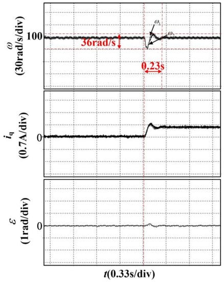
Figure 18.
Motor responses when the load are added simultaneously.
It can be seen that when the two motors are loaded at the same time, the synchronous error is small, but still bigger than that in the other places. This is because although the two loads are set to be equal in the experiment, due to the influence of the intermediate mechanical connection mechanism and the difference of resistance components, the loads may not be completely equal, with a slight difference, so there is still synchronous error when the two motors are loaded simultaneously.
6. Conclusions
The anti-disturbance integrated position synchronous control strategy of the dual permanent magnet synchronous motor system proposed in this paper can provide dual attention to the tracking performance and synchronous performance of the system when the system is disturbed. It has the following advantages:
(1) The anti-disturbance performance of the position loop can be improved by compensating the disturbance with a linear extended state observer;
(2) The synchronous performance of the system can be improved by adding a cross-coupled position synchronous compensator;
(3) The method can easily be extended to the position synchronous control of multiple motors.
Author Contributions
Conceptualization, X.Z. and Z.W.; methodology, X.Z.; software, X.Z. and T.L.; validation, X.Z. and Z.W.; formal analysis, X.Z.; investigation, X.Z.; writing—original draft preparation, X.Z.; writing—review and editing, X.Z. and Z.W.; supervision, X.Z. All authors have read and agreed to the published version of the manuscript.
Funding
This research was funded by the Tianjin Nature Science Foundation of China, grant number 20JCQNJC00370; Tianjin Higher Education Institutions Science and Technology Development Fund Project of China, grant number 2020KJ116, and Tianjin University of Technology and Education Research Startup Project of China, grant number KYQD202103.
Data Availability Statement
Not applicable.
Conflicts of Interest
The authors declare that they have no known competing financial interests or personal relationships that could have appeared to influence the work reported in this paper.
References
- Wu, Q.; Yu, L.; Wang, Y.W.; Zhang, W.A. LESO-based position synchronous control for networked multi-axis servo systems with time-varying delay. IEEE/CAA J. Autom. Sin. 2020, 7, 1116–1123. [Google Scholar] [CrossRef]
- Morozov, A.V.; Dobroskok, N.A.; Lavrinovsiy, V.S.; Mohova, O.V. Interrelated control of the multi–motor electrical drive. In Proceedings of the 2019 IEEE Conference of Russian Young Researchers in Electrical and Electronic Engineering, St. Petersburg, Russia, 28–31 January 2019; Volume 3, pp. 614–619. [Google Scholar]
- Torres, F.J.; Guerrero, G.V.; García, C.D.; Gomez, J.F.; Adam, M.; Escobar, R.F. Master-slave synchronous of robot manipulators driven by induction motors. IEEE Lat. Am. Trans. 2016, 14, 3986–3991. [Google Scholar] [CrossRef]
- Koren, Y. cross-coupled biaxial computer control for manufacturing systems. ASME J. Dyn. Syst. Meas. Control. 1980, 102, 265–272. [Google Scholar] [CrossRef]
- Perez-Pinal, F.J.; Calderon, G.; Araujo-Vargas, I. Relative coupling strategy. In Proceedings of the IEEE International Electric Machines and Drives Conference, Madison, WI, USA, 1–4 June 2003; pp. 1162–1166. [Google Scholar]
- Huang, H.; Tu, Q.; Jiang, C.; Pan, M.; Zhu, C. An electronic line-shafting control strategy based on sliding mode observer for distributed driving electric vehicles. IEEE Access 2021, 3, 38221–38235. [Google Scholar] [CrossRef]
- Chen, Y.; Yang, M.; Long, J.; Qu, W.; Xu, D.; Blaabjerg, F. A moderate online servo controller parameter self-tuning method via variable-period inertia identification. IEEE Trans. Power Electron. 2019, 34, 12165–12180. [Google Scholar] [CrossRef]
- Hsu, C.; Lai, Y. Novel online optimal bandwidth search and autotuning techniques for servo motor drives. IEEE Trans. Ind. Appl. 2017, 53, 3635–3642. [Google Scholar] [CrossRef]
- Sun, D. Position synchronous of multiple motion axes with adaptive coupling control. Automatica 2003, 39, 997–1005. [Google Scholar] [CrossRef]
- Jin, H.Y.; Zhao, X.M. Dual linear motors servo system synchronous control based on sugeno type fuzzy neural network and complementary sliding mode controller. Trans. China Electrotech. Soc. 2019, 34, 2726–2733. [Google Scholar]
- Wang, Y.S.; Su, C. Robust cross-coupled synchronous control design for multi-axis systems. Control. Eng. China 2021, 28, 1615–1620. [Google Scholar]
- Kuang, Z.; Gao, H.; Tomizuka, M. Precise linear-motor synchronous control via cross-coupled second-order discrete-time fractional-order sliding mode. IEEE/ASME Trans. Mechatron. 2021, 26, 358–368. [Google Scholar]
- Lu, S.K.; Wang, X.C. Observer-Based Command Filtered Adaptive Neural Network Tracking Control for Fractional-Order Chaotic PMSM. IEEE Access 2019, 7, 88777–88788. [Google Scholar] [CrossRef]
- Liu, Y.C.; Laghrouche, S.; Depernet, D.; Djerdir, A.; Cirrincione, M. Disturbance-Observer-Based Complementary Sliding-Mode Speed Control for PMSM Drives: A Super-Twisting Sliding-Mode Observer-Based Approach. IEEE J. Emerg. Sel. Top. Power Electron. 2021, 9, 5416–5428. [Google Scholar] [CrossRef]
- Lin, P.; Wu, Z.; Liu, K.Z.; Sun, X.M. A Class of Linear–Nonlinear Switching Active Disturbance Rejection Speed and Current Controllers for PMSM. IEEE Trans. Power Electron. 2021, 36, 14366–14382. [Google Scholar] [CrossRef]
- Gao, Z.Q. Scaling and bandwidth-parameterization based on control tuning. In Proceedings of the 2004 American Control Conference, Denver, CO, USA, 4–6 June 2003; pp. 4989–4996. [Google Scholar]
- Wang, H.Q.; Huang, H. Property and application of extended state observer. Control. Decis. 2013, 28, 1078–1082. [Google Scholar]
- Zhang, J.; Yang, X.; Liu, Y.X.; Yao, X.X. Performance evaluation for active disturbance rejection with high-order line extended state observer. Control. Decis. 2015, 30, 1162–1170. [Google Scholar]
- Mao, H.; Li, W.; Jiang, D.; Feng, X. State Estimation and Performance Analysis Based on Linear Extended State Observer for Permanent Magnet Synchronous Motor. Trans. China Electrotech. Soc. 2019, 34, 2155–2165. [Google Scholar]
- Sun, K.; Xu, Z.L.; Gai, K.; Zou, J.Y.; Dou, R.Z. A novel position controller of PMSM servo system based on active-disturbance rejection controller. Proc. CSEE 2007, 27, 43–46. [Google Scholar]
- Zuo, Y.F.; Zhang, J.; Liu, C.; Zhang, T. Integrated design for permanent magnet synchronous motor servo systems based on active disturbance rejection control. Trans. China Electrotech. Soc. 2016, 31, 51–58. [Google Scholar]
- He, Z.H.; Yu, H.S. Coordinated sliding mode control of ring-coupled multi-motor based on active disturbance rejection and observer. Micromotors 2021, 54, 48–55. [Google Scholar]
- Wang, X.Y.; Liu, Y.C.; Zhong, Y.B.; Gao, J. Multi-motor coordinated system based on self-correction active disturbance rejection control. Modul. Mach. Tool Autom. Manuf. Tech. 2021, 2, 77–81. [Google Scholar]
- Geng, Q.; Li, L.; Zhou, Z.Q.; Wang, Z.Q.; Shi, T.N.; Xia, C.L. Speed synchronous control of disturbance rejection of dual-PMSM system. Proc. CSEE 2021, 5, 1–10. [Google Scholar]


Publisher’s Note: MDPI stays neutral with regard to jurisdictional claims in published maps and institutional affiliations. |
© 2022 by the authors. Licensee MDPI, Basel, Switzerland. This article is an open access article distributed under the terms and conditions of the Creative Commons Attribution (CC BY) license (https://creativecommons.org/licenses/by/4.0/).