1. Introduction
Oil, gas, and coal are types of conventional energy sources that are not sustainable. Recently, as a result of global geopolitical issues, there is clear evidence that basing energy policy solely on these traditional energy sources is unreliable. Furthermore, the recent remarkable change in the climate is another critical issue, which is related to the excessive use of conventional fuels. Energy policy based on reducing the dependence on conventional fossil fuels, expanding energy diversification, and moving towards renewable sources offers a reliable, secure, and clean alternative. The challenge in utilizing renewable energy sources, however, is securing a well-known and mature energy conversion technology that is low in cost and has no negative environmental impacts [
1]. Recent efforts in research and industry have resulted in a number of rapidly expanding technologies that can be used to exploit renewable energy sources. Solar radiation, wind power, tides and waves, water power, and geothermal energy are common examples of renewable energy sources. With the exception of geothermal energy, solar radiation is the source of all other available energy sources on our planet. Energy from the sun is an abundant source of clean and renewable energy that is capable of satisfying large power needs and large electricity demands [
2]. The proven technologies that are used to exploit solar energy include water and air heating systems, cooling and freezing systems, water desalination systems, power generation systems, and others.
A solar chimney power plant, a promising technology that has been proven to be applicable on a large scale, is one of the options available for capturing the power of the sun and converting it to electricity [
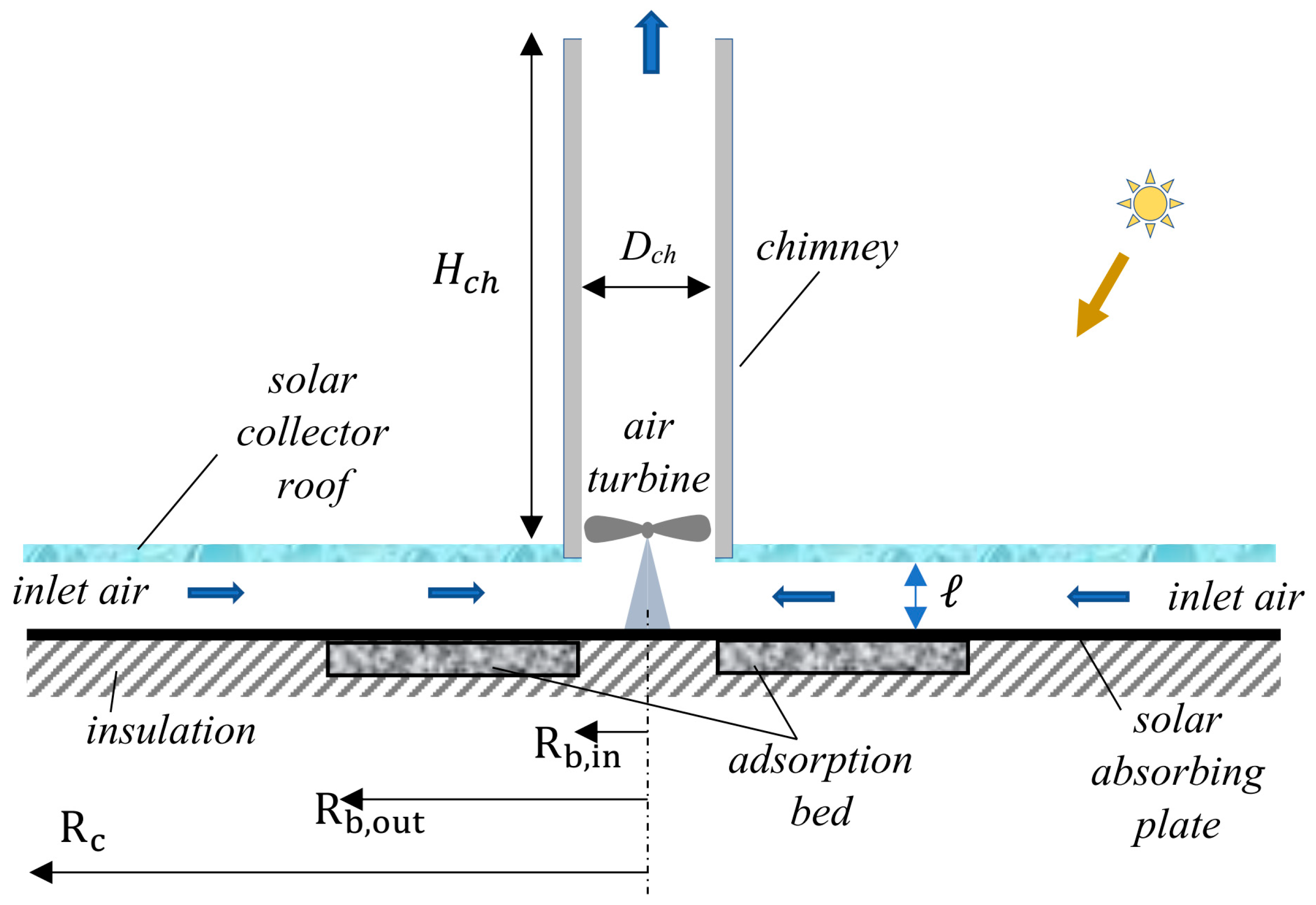
3]. Conventional solar chimney power production systems are simple in construction as well as in theory. These systems consist of a large solar collector, a tall chimney, and an air turbine placed at the chimney’s inlet. The air under the transparent solar collector cover is heated by the solar radiation and is driven upwards inside the chimney by the buoyancy effect. The turbine extracts some of the air momentum and produces mechanical power, which is converted to electricity through an electric generator. The first successfully operated experimental prototype of the solar chimney power plant was built in Manzanares, Spain, in 1982 [
4]. The constructed solar collector was 244 m in diameter, and the chimney height was 194.6 m. The rated power output from this pilot plant was found to be 50 kW [
5].
The solar chimney power plant is characterized by a low solar-to-electricity conversion efficiency. For instance, the average conversion efficiency of the Manzanares pilot plant was less than 0.1% [
5]. The main parameters that determine the efficiency of the solar chimney power plant are the solar collector area and the chimney height. Several studies have been introduced in the literature to improve the performance and efficiency of solar-chimney-power-generating systems. Some of the research work focused on enhancing conventional system performance. Caicedo et al. [
6] investigated the performance enhancement of the solar chimney power plant through using a radial flow turbine instead of the axial flow turbine in the conventional system. The authors theoretically simulated the radial turbine performance by implementing computational fluid dynamics. They found that the power output from the radial flow turbine was larger than the power generated by the basic axial flow turbine. In another study, a three-dimensional simulation of a solar chimney that had an installed axial flow turbine was conducted in [
7] using computational fluid dynamics.
One line of research tried to improve the performance of the solar chimney power plant by putting together different technologies in a hybrid system [
8]. The hybrid solar chimney power plant comprises the integration of other components, such as water desalination. A method for extracting water from humid air and using a hybrid solar chimney power plant was presented in [
9]. In [
10], the conventional solar chimney was integrated with a seawater sprayer at the chimney’s inlet, in place of the turbine, for the purpose of water desalination. More research work that combines a solar chimney power plant and seawater desalination was reviewed by Maia et al. [
11]. Abdelsalam et al. [
12] introduced a modification to the conventional solar chimney power plant to increase the power generation. An extra outer cocentric chimney was integrated with the conventional inner chimney in their work. The outer chimney comprised 10 cooling towers; each cooling tower was integrated with a water sprayer at the top and a turbine at the bottom. Numerical simulation of their proposed double-chimney system revealed a thermal efficiency that was 200 times greater than the conventional solar chimney power plant. An experimental study was conducted on a small-scale prototype of a hybrid solar chimney power and seawater desalination system [
13]. The results from their experimental work revealed that the hybrid system had a higher efficiency compared with the conventional one. A hybrid solar chimney system for power production and seawater desalination with water sprinklers placed at the chimney top was theoretically studied [
14]. The results indicated that the electrical energy produced by the hybrid solar chimney system was larger than that produced by the traditional solar chimney power system.
The conventional solar chimney power plant was integrated with photovoltaic cells to increase the power produced. The study in [
15] investigated the performance of a hybrid system composed of a solar chimney power plant integrated with seawater desalination and photovoltaic. The photovoltaic panels were placed at the circumference of the solar collector roof. The obtained results showed an increase in the production of electric power from 380 to 494 MWh per year. A modified solar chimney system was introduced and studied theoretically in [
16]. This modified system integrated photovoltaics and water desalination with the solar chimney power plant. The numerical simulation results of the hybrid system showed an increase in the annual power production compared with the standalone photovoltaic system. The sensitivity analysis of the hybrid system revealed that the height of the chimney is the most significant parameter for system performance [
16]. Semitransparent photovoltaics were integrated into the solar collector roof of a solar chimney to increase the power production through cooling of the photovoltaics [
17]. The system had no installed turbine, and the chimney draft was totally used to generate an air flow to cool the photovoltaics. The system performance was found to be dependent on the intensity of solar radiation and the photovoltaics packing factor. The study showed also that the amount of electricity produced by the photovoltaics increased by 29% when the solar chimney was implemented as a cooling system for the semitransparent photovoltaics. Seawater desalination and transparent photovoltaic cells were integrated with a solar chimney power plant in the study [
13]. The results of the sensitivity analysis revealed that the hybrid system efficiency was significantly influenced by variations of all geometric parameters and the operating conditions. Reference [
18] conducted an experimental and numerical study on a solar chimney/photovoltaic hybrid system. The measurements were recorded at different climatic conditions, and a theoretical simulation was carried out to determine the air flow field. Results from the study showed that the integrated solar chimney/photovoltaic system produced power at an efficiency two orders of magnitude higher than the efficiency of the conventional system. The performance of an integrated solar chimney power/photovoltaic system was investigated in [
19]. Their results revealed that the most effective part of the solar collector, which is suitable for cooling the photovoltaic panels, was about 80% of the collector area. Furthermore, research in [
20] revealed that integrated solar chimney power and photovoltaic panels generate more electric power than a stand-alone conventional solar chimney power system.
Thermal energy storage was integrated with the conventional solar chimney power plant to enhance the night operation of the system. Sedighi et al. [
21] numerically studied the effect of thermal energy storage on the operation and performance parameters of the system. In another research work, the performance of an experimental prototype of a solar chimney power plant that used paraffin as a thermal phase change material was investigated by Bashirnezhad et al. [
22]. Further theoretical and experimental research work on the subject was reviewed by Zhou et al. [
23] and Kasaeian et al. [
24].
Solar energy has been used to drive cooling and refrigeration systems, which are operated by thermal energy. These thermally driven cold-generating systems include steam ejector cooling systems, absorption refrigeration systems, and solid-sorption cold production systems. In solar-driven cooling systems, the solar thermal radiation is collected, or concentrated, and is then used to drive the cooling cycle [
1]. The solid-sorption cooling thermodynamic cycle is similar to the mechanical refrigeration thermodynamic cycle except that the compressor operation is different. Unlike the mechanically driven compressor in vapor compression systems, the adsorption reactor in the solid-sorption cooling cycle performs as a compressor that is driven by thermal energy [
25].
The solid-sorption reactor contains the solid adsorbent material and the refrigerant gas. The commonly used porous solid-sorption material could be activated carbon, silica gel, and zeolite. The refrigerant fluids that are commonly utilized include methanol, ammonia, and water [
26]. It is worth mentioning that the solid-sorption cold-generating cycle has the advantage of being driven by low-quality thermal energy compared with the absorption and steam ejector cycles. For instance, a 50 °C thermal energy source is capable of activating the refrigerant in the adsorption reactor, if a silica gel/water adsorption pair is used [
27]. This makes solar-powered adsorption-based cold generation systems an attractive research field [
28]. In the research literature, there are a number of studies that have been conducted to develop, improve, and change these systems either experimentally, theoretically, or both [
29].
A conventional solar chimney power plant is intermittent in operation and produces power during the solar radiation availability period only, if there is no thermal energy storage integrated with the system. In the adsorption cooling system, the reactor releases heat into the environment during the bed isosteric cooling process and during the adsorption process. Although various hybrid solar chimney power generation systems have been introduced in the literature, to the best of our knowledge, there has been no research work introducing the integration of solid-sorption cooling with the solar chimney power plant. Therefore, the present paper is devoted to covering this gap in research and presenting a novel hybrid solar chimney power and adsorption cold production system. The purpose of the proposed system is to enhance the system’s utilization of solar energy by recovering the reactor’s released heat and reusing it to augment the output power. Moreover, the air turbine in the proposed novel system produces a daylong continuous power output compared with the intermittent power produced in conventional solar chimney power plants.
3. Results and Discussions
In order to validate the numerical solution and the accuracy of the mathematical calculations, an overall thermal energy balance for the solar collector has been conducted. All thermal energy components pertaining to the solar collector have been calculated at every time step. These thermal components are plotted with respect to time, as illustrated in
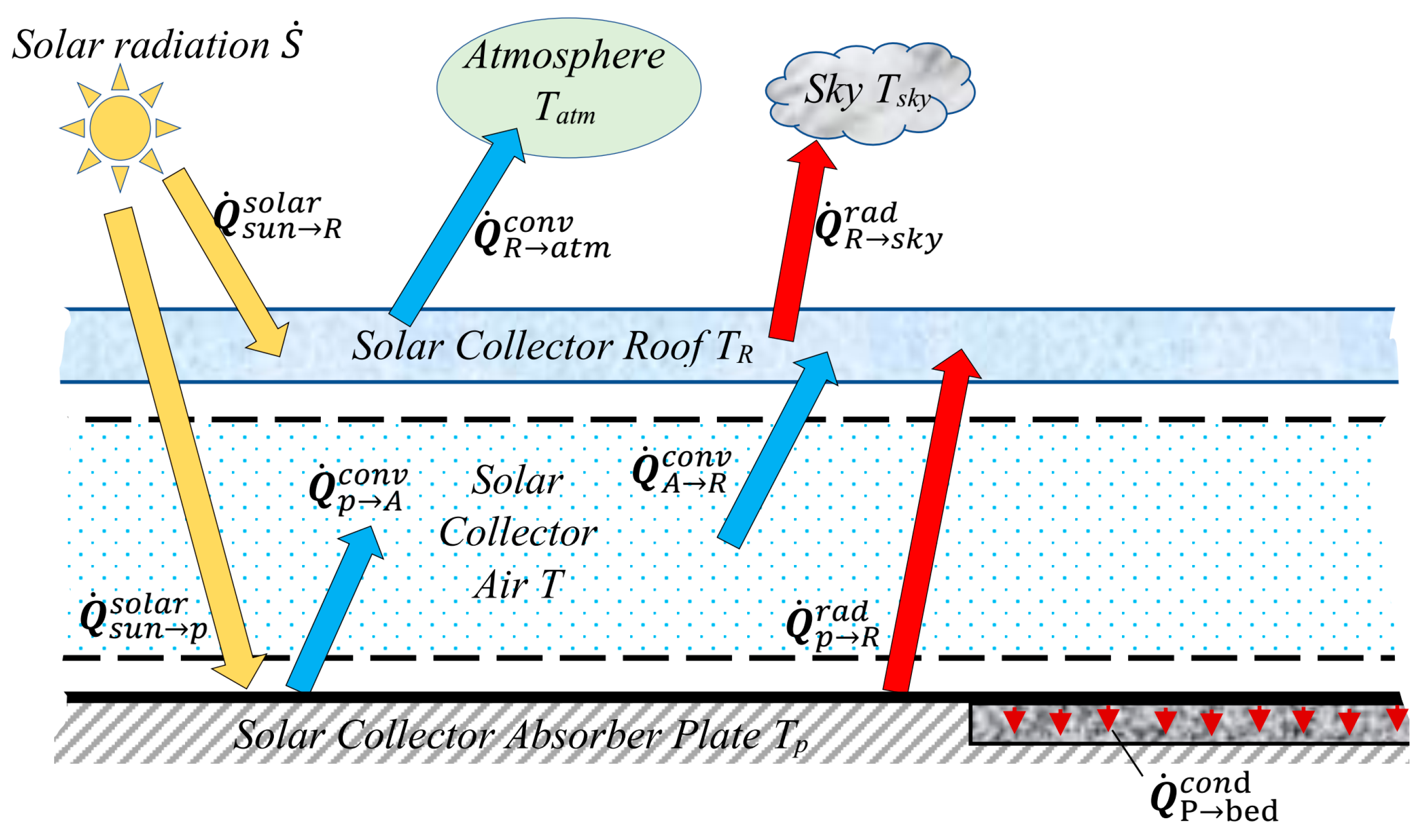
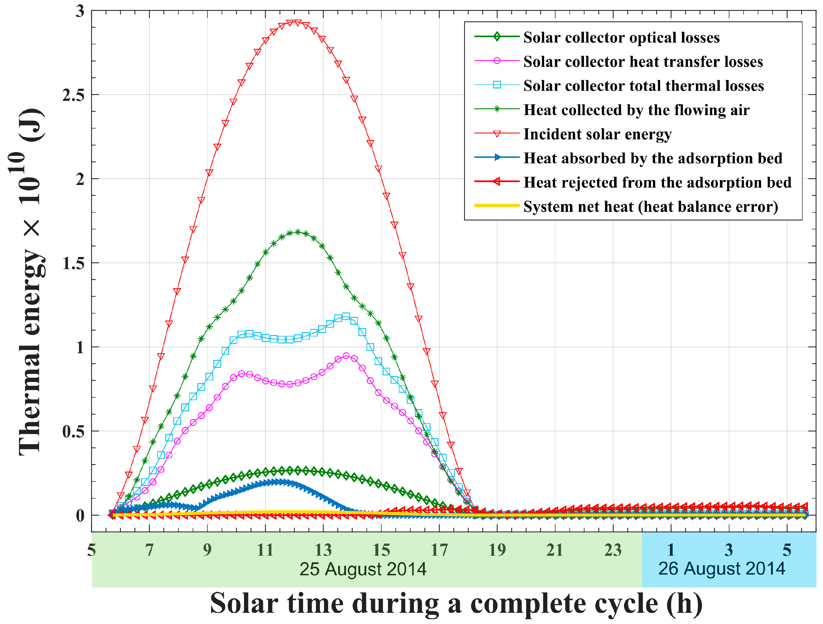
Figure 3. The solar collector’s overall thermal energy balance can be expressed in terms of system net thermal energy (i.e., thermal energy balance error). The system’s net thermal energy equals the difference between its input and output thermal energy. The incident solar energy and the rejected heat from the adsorption reactor represent the input thermal energy to the solar collector. The output thermal energy part includes the thermal energy carried by the solar collector’s flowing airstream, the solar collector roof total losses (i.e., the sum of optical and thermal losses), and the adsorption reactor activation and desorption heat. As shown in
Figure 3, the solar collector net heat balance, which represents the numerical error, attains a near-zero value at any time during the whole dynamic simulation cycle. Consequently, the result of this numerical experiment validates both the mathematical model and the numerical calculations.
The total solar incident thermal energy during a complete operating cycle is found to be
. As illustrated in
Figure 3, most of the incident solar energy is transferred to the solar collector airstream. The air flow in the solar collector captures about
, which is nearly 55.84% of the total incident solar energy. Another considerable part,
, which is nearly 42.10% of the incident solar energy, is lost from the solar collector through the transparent roof to the surrounding atmosphere. As a consequence, the total thermal efficiency of the solar collector is about 57.9%. The solar collector optical losses represent about 9.05% of the incident solar energy, about
, whereas the solar collector heat transfer losses represent about 33.05% of the incident solar energy, at the amount of
. The values of the solar collector optical and thermal efficiencies are found to be 90.95% and 66.95% of the total incident solar energy, respectively.
Figure 3 plots the development of the solid-sorption reactor’s uptake of thermal energy throughout the system’s operating cycle. At the beginning of the cycle, the adsorption bed starts its first thermodynamic process, which is the activation and isochoric pre-heating process. During this process, the bed is heated at a constant volume, and the uptake of thermal energy continues until the bed pressure increases from the evaporator pressure to the condenser pressure. At 08:40, the activation preheating process ends, and the second thermodynamic process of the adsorption bed starts, which is the bed isobaric and desorption process. During the desorption process, the refrigerant is released out of the bed at the constant pressure of the condenser. Releasing the refrigerant from the silica gel solid-sorption substance is an endothermic process that requires supplying heat, known as the “heat of desorption”. The amount of desorption heat is larger than the heat required to preheat the adsorption bed. Switching from the isochoric preheating process to the isobaric desorption process of the adsorption bed explains the sudden change in behavior of the adsorption bed uptake of thermal energy at 08:40, as shown in
Figure 3. As the desorption process continues, the heat absorbed by the reactor increases. This increase is due to the increase in solar radiation. The reactor’s absorbed heat reaches a maximum at noon, corresponding to the maximum solar radiation. After noon, the thermal energy absorbed by the bed declines and follows the decreasing trend of the solar radiation. The solar radiation continues to decline until it reaches a value that is unable to cause a further increase in the adsorption reactor temperature, at 14:46 solar time. As a result, the adsorption bed stops the release of more refrigerant vapor towards the condenser, and the desorption isobaric thermodynamic process ends. The third thermodynamic process of the adsorption cycle, which is an isochoric cooling process, starts at 14:46. Therefore, after 14:46 solar time, the heat absorbed by the adsorption bed maintains a zero value until the end of the cycle, as shown in
Figure 3. Furthermore, the total absorbed heat during the activation preheating process and the isobaric desorption process is found to be equal to 3.86% of the incident solar energy, about
. Moreover, during the adsorption process, which is an exothermic process, an amount of
, about 2.42% of the incident solar energy, is released from the sorption reactor.
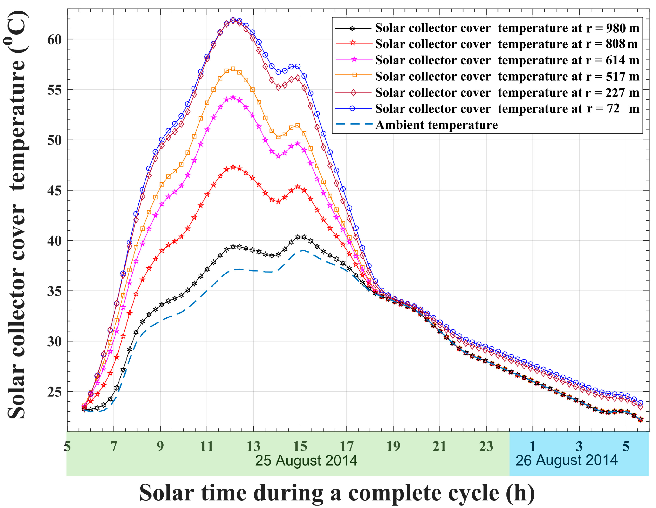
Figure 4 plots the development of solar collector roof temperature with respect to solar time at different radii of the collector. The ambient temperature variation with daytime is illustrated in
Figure 4 as well. It is observable that the solar collector roof temperature at all radii increases at the beginning of the cycle; reaches a maximum at noon, around 12:00 p.m.; and then starts to decline during the remaining cycle time. Furthermore, the roof temperature profile with respect to solar time is observed to be affected by the ambient temperature changes throughout the day, as illustrated in
Figure 4. For instance, the ambient temperature is 37 °C at 14:00 and increases to 39 °C at 15:00. This increase in ambient temperature results in decreasing the heat transfer losses from the roof and, as a result, an increase in the roof temperature at all radii. After 15:00 solar time, the temperatures of the solar collector cover at all radii continue to decrease, following the continuous drop in the ambient temperature. Additionally, as shown in
Figure 4, the rapid drop in roof temperatures at all radii is caused in part by the decrease in solar radiation that hits the roof. Moreover, the roof temperature distribution shows higher values while moving towards the solar chimney. The largest roof temperature is found to be 62 °C, which is noticed at noon, near the solar chimney inlet. After sunset, at 06:32 p.m., positions on the roof at radii greater than the adsorption bed radius, which is 500 m, will be in thermal balance with the ambient atmosphere, and temperatures at these points will maintain a value near the ambient temperature. Meanwhile, at radii less than 500 m, the roof temperature is higher than the ambient temperature for roof positions that are facing the adsorption bed. At the end of the operation cycle, the solar collector roof maintains nearly a 2 °C temperature difference above the ambient temperature at these positions (
Figure 4). This temperature difference results from the thermal energy release from the adsorption reactor during the isochoric bed cooling process and the isobaric adsorption process.
For solar collector absorber plate radii that are greater than the adsorption reactor radius (
),
Figure 5 illustrates the temperature development with time at various points. Generally, the maximum absorber plate temperature is noticed around noon, which corresponds to the maximum solar radiation time, for all of these points. It is obvious that the solar collector absorber plate temperature increases in the inward radial direction and reaches its maximum, about 77 °C, near the outer edge of the adsorption bed. Nonetheless, after the sunset time of 06:32 p.m. until the cycle ends, the solar collector absorber plate reaches a thermal equilibrium with the surrounding atmosphere, and its temperature maintains the value of the ambient temperature at all points, as shown in
Figure 5.
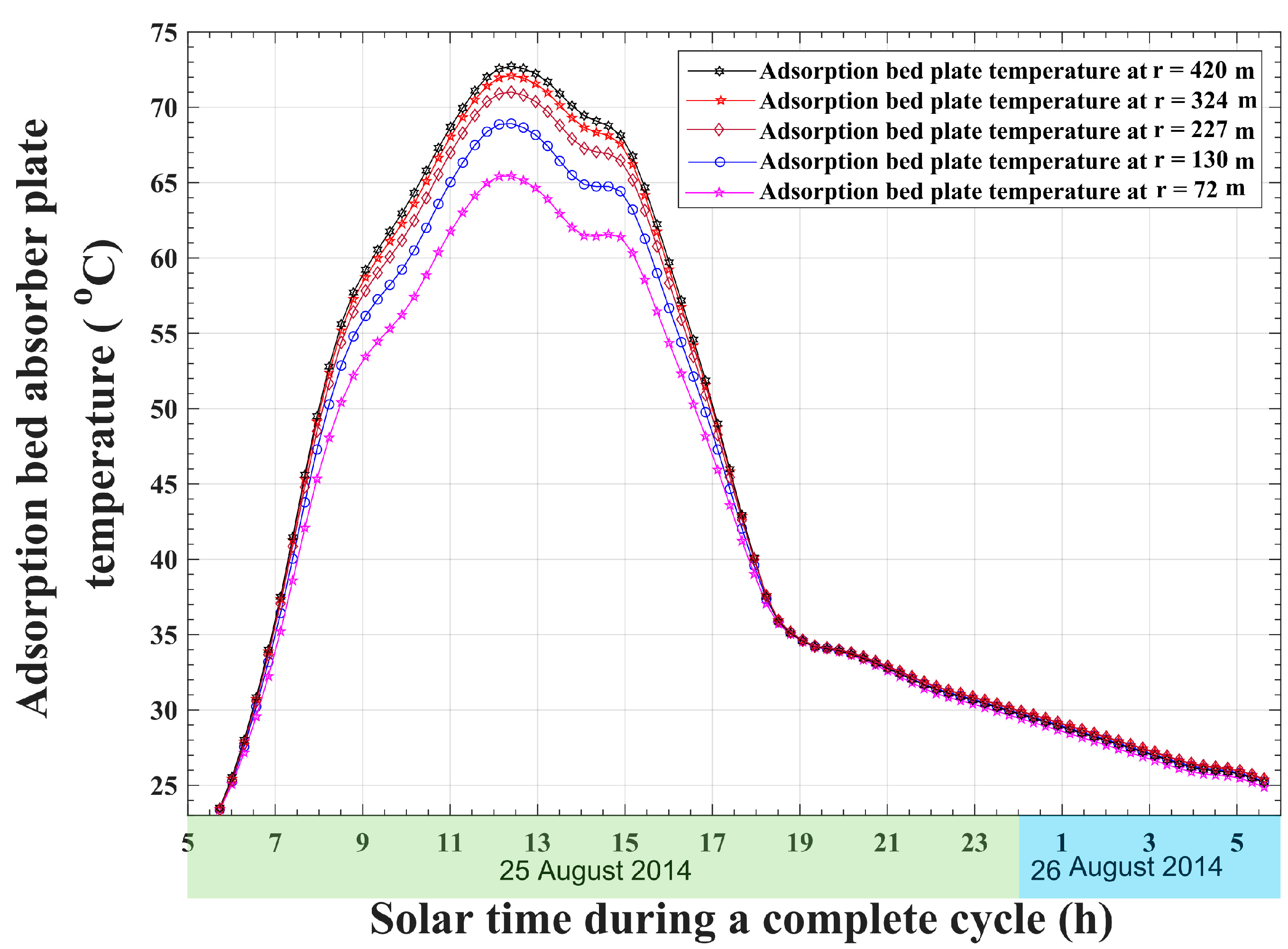
The time variations of the adsorption bed absorber plate temperatures at different radial locations (
) are plotted in
Figure 6. It is noticeable that the behavior of the temperature curves resembles temperature profiles for the solar collector plate, as shown in
Figure 5. Nevertheless, the remarkable difference is the descending trend in the inward direction. This decreasing trend of temperature is justified by the heat absorbed by the adsorption bed during the adsorption reactor isosteric cooling and isobaric desorption processes. Furthermore, the air velocity increases in the inward radial direction due to the decrease in the solar collector cross-sectional area. As a result, the convection heat transfer coefficient between the air flow and the absorber plate increases in the direction towards the center of the solar collector. After sunset, the adsorption bed solar absorber plate maintains a very small temperature gradient, with a difference of less than 0.5 °C between its outer radius and inner radius temperatures. In the inward radial direction, it is clear that there is an enhancement of the heat transfer coefficient due to the increase in the inward air radial velocity. As a consequence, the parts of the adsorption bed absorber plate near the center of the solar collector maintain lower temperatures compared with those near the outer radius of the adsorption reactor.
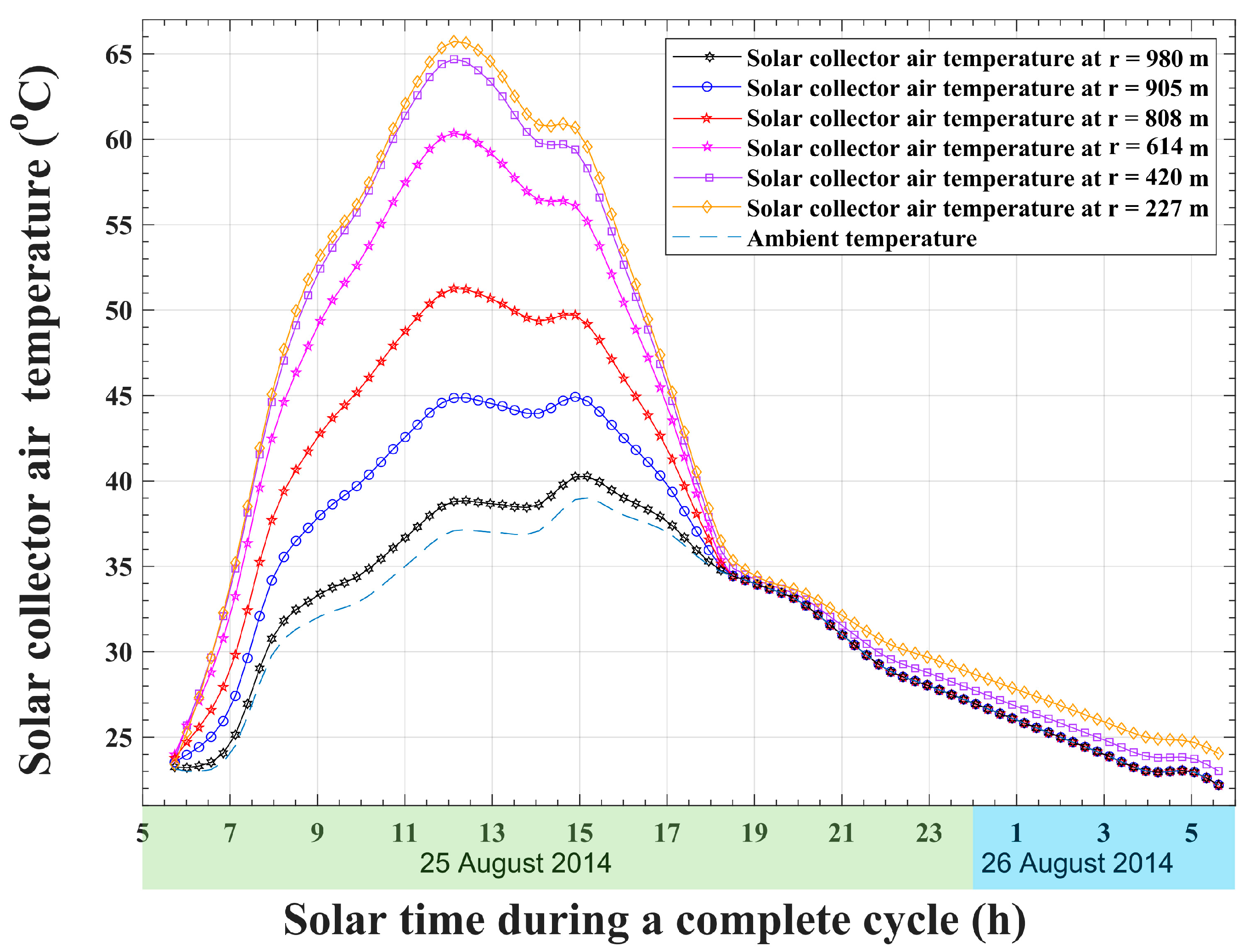
The temperature development of the solar collector air flow with respect to solar time at various radial positions is shown in
Figure 7. It is obvious that, the air temperature increases continuously in the inward direction, from the solar collector inlet to the chimney inlet, at all times. Higher air temperatures are noticed at noon, corresponding to the solar radiation peak. At the end of the operational cycle, air at the solar collector exit attains a temperature increase of about 2 °C due to the heat released from the adsorption reactor during the bed isochoric cooling and the bed adsorption processes.
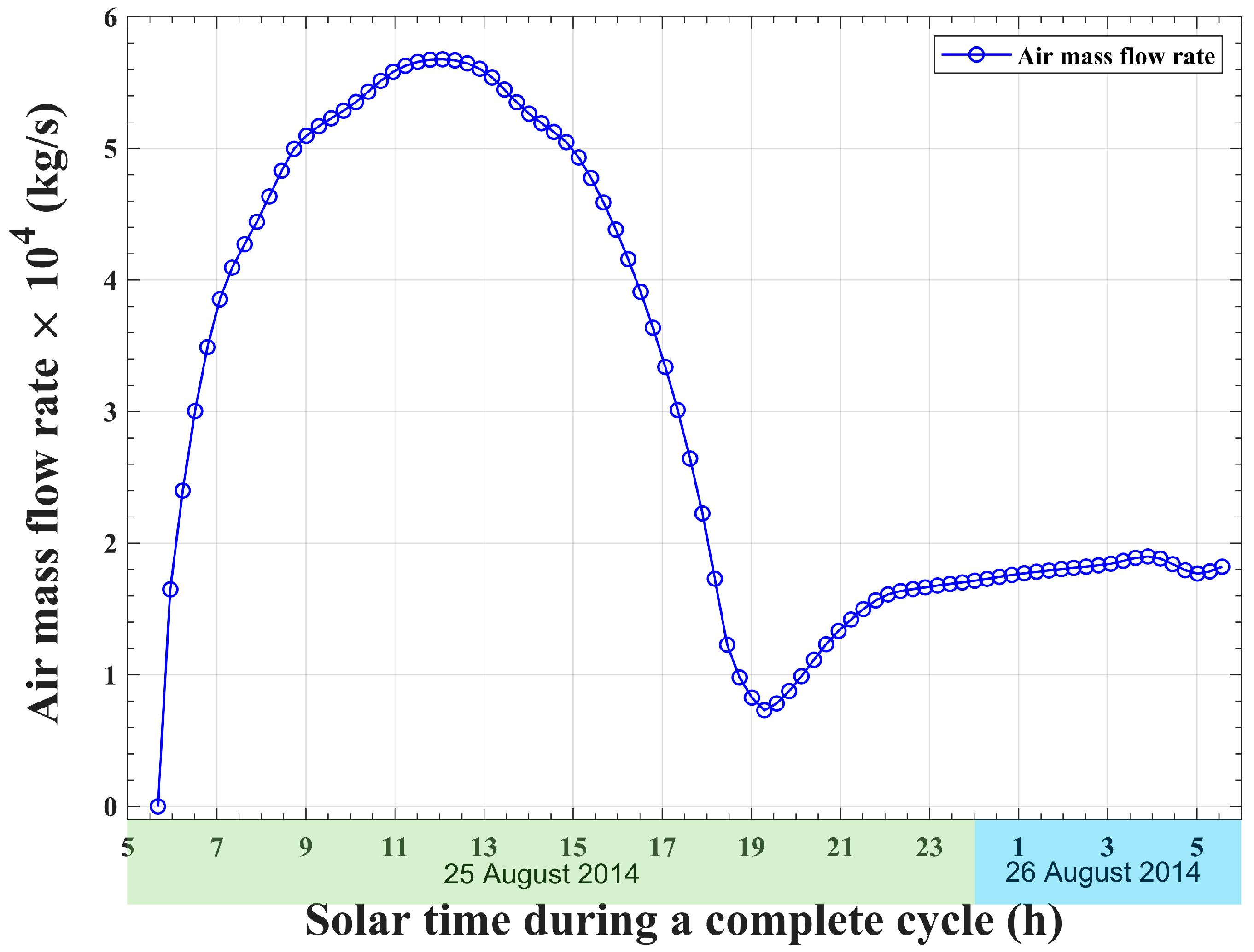
The variation of air mass flow rate through the system during the complete operating cycle is illustrated in
Figure 8. At the beginning of the cycle, after sunrise at 05:41 a.m., a rapid increase in the system air mass flow rate is noticed due to the corresponding rapid increase in solar radiation. The maximum air mass flow rate, about
, is observed at the peak of the solar radiation at noon. This peak in air flow is a result of the corresponding peak in the air temperature rise through the solar collector, which leads to a maximum chimney draft. After this peak, a descent in the behavior of the air flow through the system is observed due to the corresponding declination in solar radiation and the resulting decrease in the chimney’s draft. At 19:21 p.m., the system reaches a low value of air mass flow rate, which is approximately
, at the end of the isosteric cooling phase of the adsorption bed. At the beginning of the adsorption phase, the heat of adsorption that is released from the bed leads to a temperature increase of the solar collector airstream. Consequently, the resulting increase in the chimney’s draft and the increase in air velocity inside the chimney lead to increasing the mass flow rate of the air, as shown in
Figure 8.
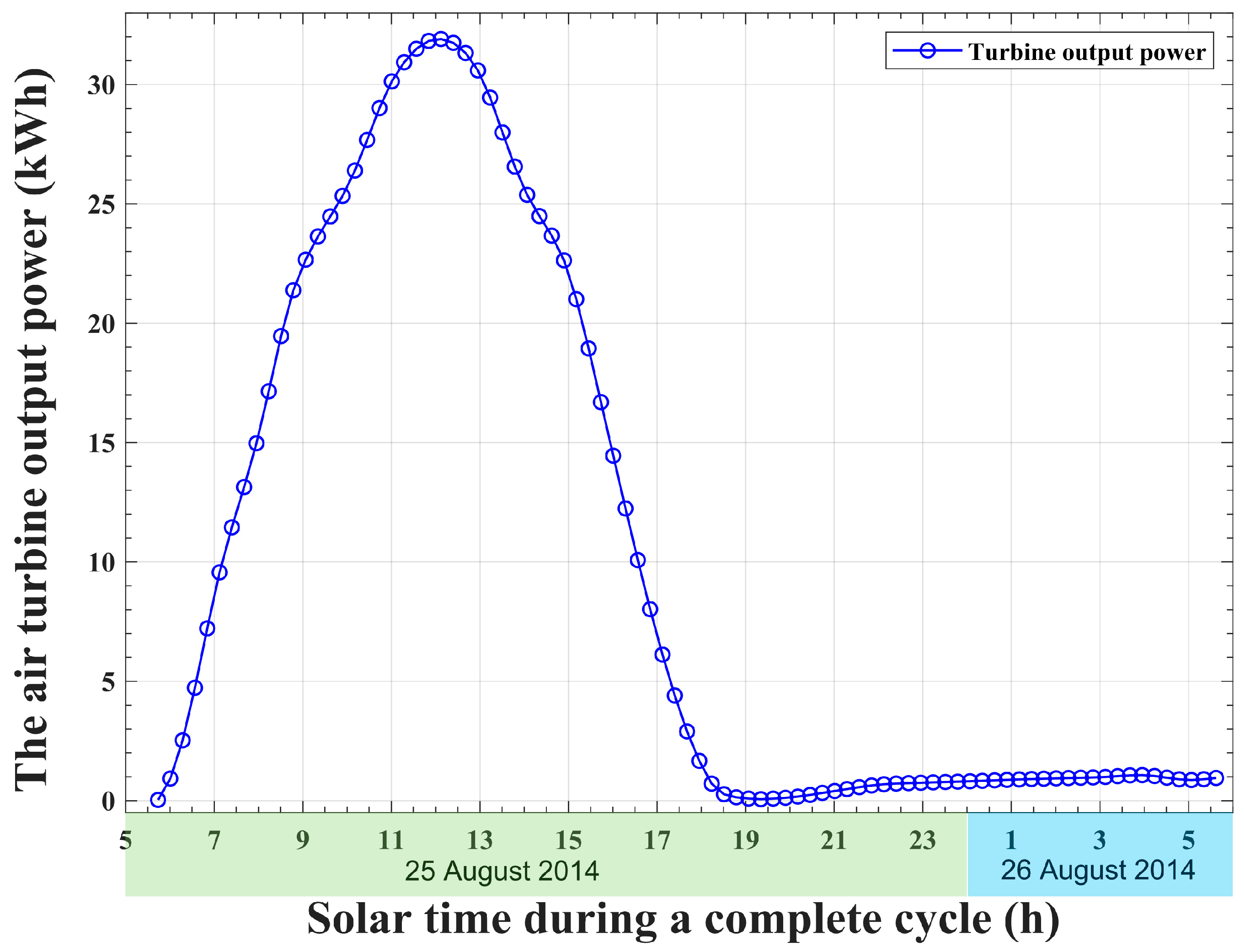
The amount of electric power produced by the air turbine inside the chimney is strongly related to the air mass flow rate. As a result, the electricity produced by the solar chimney power plant system is expected to maintain a profile that resembles the air mass flow rate profile, as illustrated in
Figure 9. For an air turbine total efficiency of 85%, the maximum output turbine power is found to be 32 kWh corresponding to the solar radiation peak, which takes place at 12:00 p.m. It is also noticed, from
Figure 9, that the air turbine continues to produce power even after the sunset. This is because of the released heat from the sorption bed during the isosteric cooling and isobaric adsorption phases. This released heat leads to a temperature rise in the air flow. Consequently, the driving potential of the air flow through the system and the electric power produced by the air turbine are increased. The total electric power produced by the air turbine is found to be 87.74 MWh, and the corresponding solar-to-electricity conversion efficiency is determined to be 0.4%.
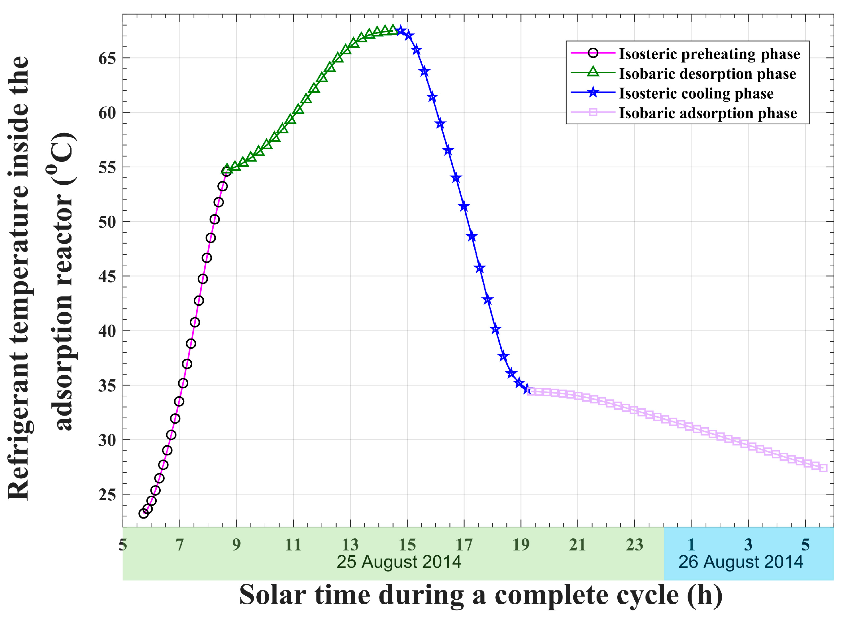
The operation of the integrated solid-sorption water chiller is illustrated in
Figure 10,
Figure 11 and
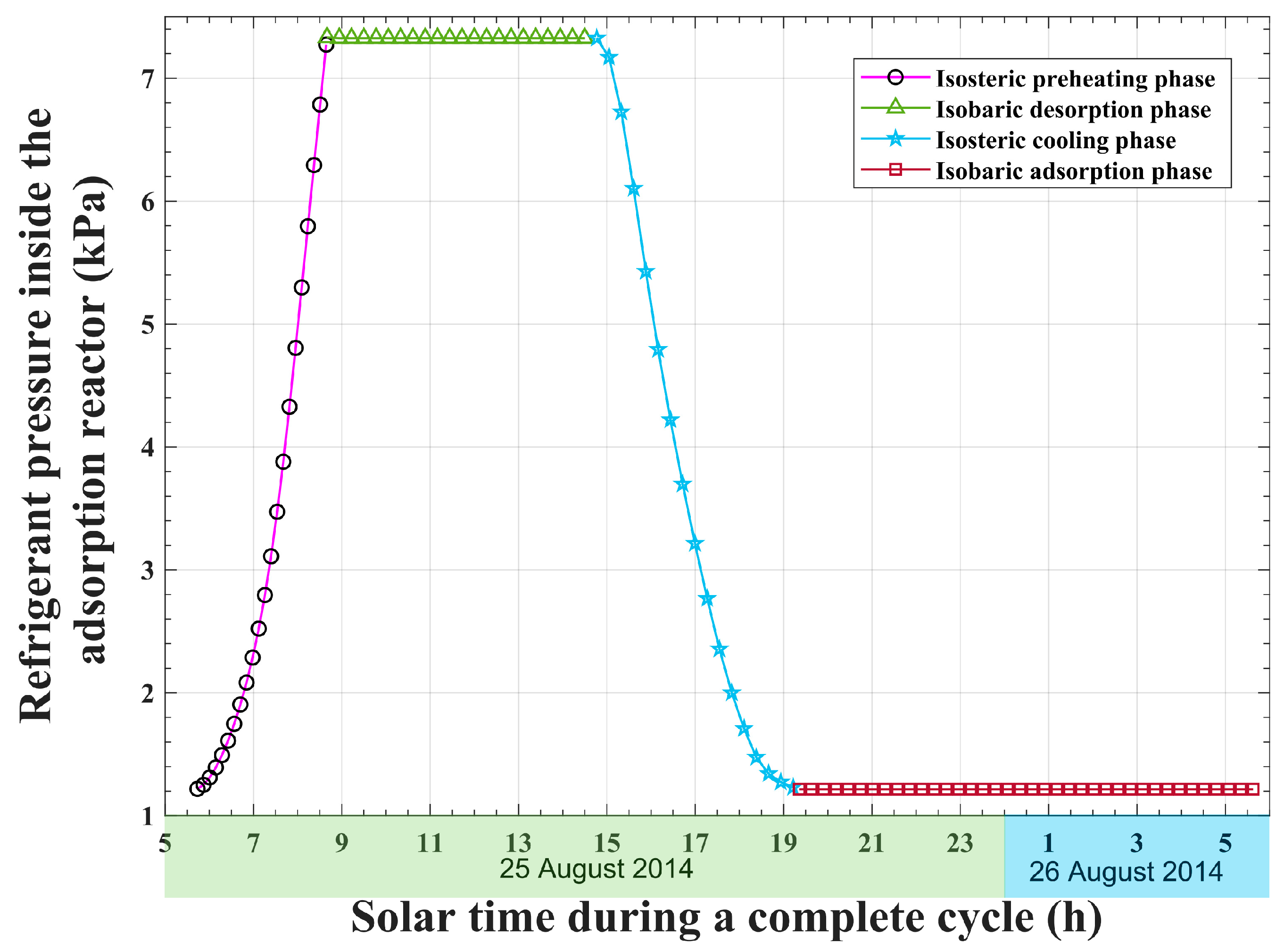
Figure 12. At the beginning of the cycle, the silica gel adsorbent material is preheated by the incident solar thermal energy from the initial temperature, which equals the ambient temperature. The bed isosteric preheating phase continues until 08:40 solar time, when the silica gel reaches an activation temperature of 54.74 °C, as shown in
Figure 10, which corresponds to a condenser pressure of 7.32 kPa (
Figure 11). It is found that 0.61% of incident solar thermal energy (about
) is consumed to bring the bed to the activation state. The refrigerant vapor inside the bed is released from the adsorbent material pores and moves towards the condenser as a result of solar radiation heating. During the isobaric desorption process, the reactor temperature continues to elevate, as shown in
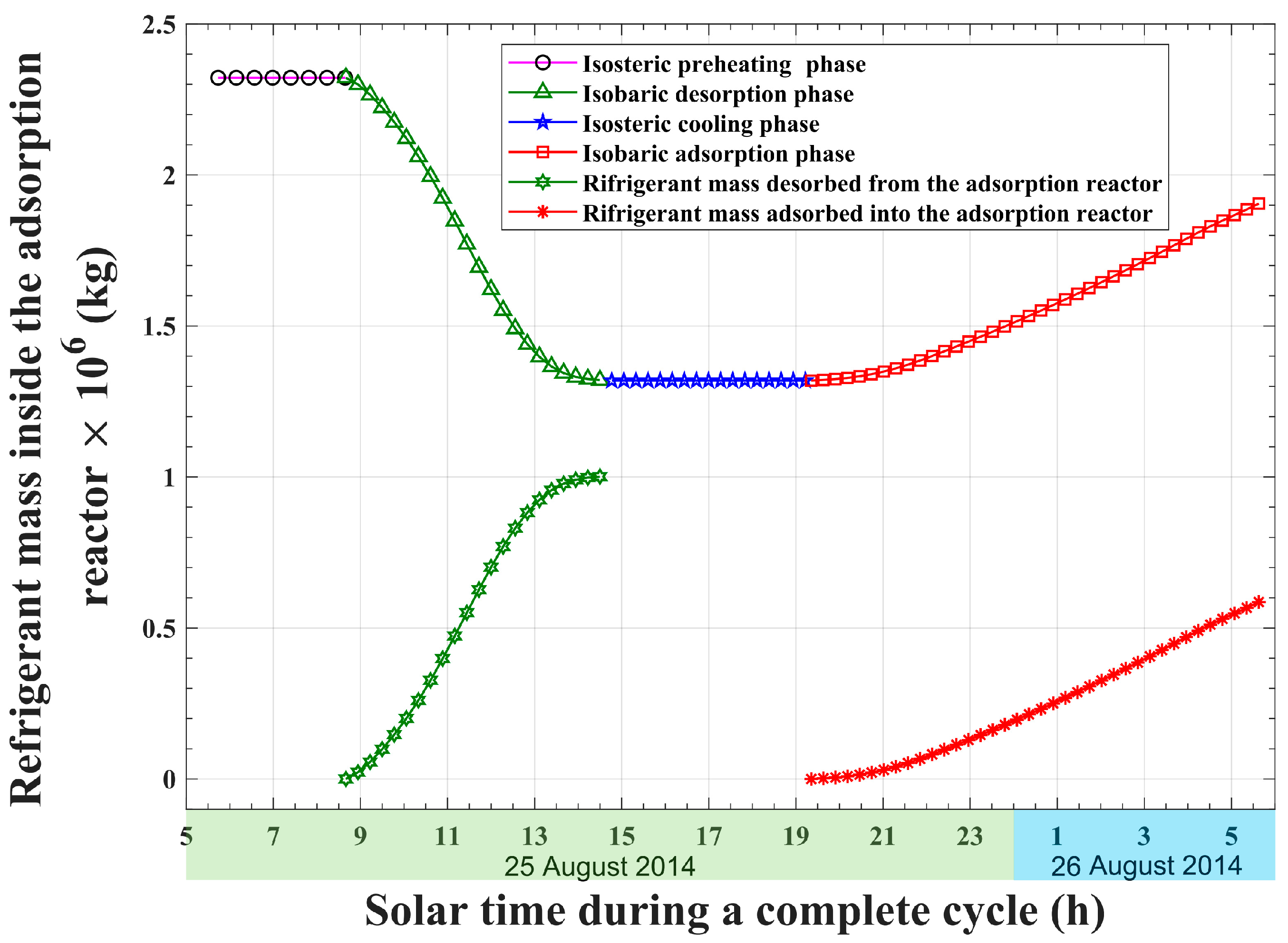
Figure 10. Furthermore, as the reactor temperature elevates, the refrigerant mass that is stored inside the bed continues to decline, as illustrated in
Figure 12. It is found that an amount of
(about 3.25% of incident solar thermal energy) is absorbed by the solid-sorption reactor. Moreover, the total mass of the refrigerant that is released from the reactor is found to be about
.
The incident solar thermal energy continues to decline until it reaches a value that is unable to cause a further increase in the adsorption reactor temperature, at 14:46 solar time. Consequently, the releasing of the refrigerant out of the bed stops, and the bed undergoes a constant volume cooling process, as shown in
Figure 10,
Figure 11 and
Figure 12. The bed isochoric cooling process continues until 19:21 solar time when the reactor pressure reaches 1.2 kPa, which is the evaporator pressure, as plotted in
Figure 11. It is found that the adsorption bed transfers an amount of
of thermal energy to the solar collector’s air flow. The last process in the adsorption cooling cycle is the isobaric adsorption process, during which the adsorption bed receives the refrigerant vapor coming out of the evaporator, and the heat of adsorption is released from the reactor. It is found that the adsorption reactor releases an amount of
during this process.
A major advantage of the introduced hybrid adsorption chiller and solar chimney power plant is the recovery of the adsorption bed waste thermal energy. In the basic adsorption cooling system, the thermal energy released from the adsorption reactor during the isochoric cooling and isobaric adsorption processes should be dissipated into the surrounding environment in order to complete the thermodynamic cooling cycle. It is noteworthy that about 62.6% of the total thermal energy transferred to the adsorption bed is dissipated into the environment, and this is a considerable amount. In the combined system presented in this paper, this thermal energy is not wasted, yet it is recovered and recycled by transferring it to the solar collector air. As a consequence, this recovered and recycled thermal energy leads to a temperature rise in the air flow after sunset, as illustrated in
Figure 7. This rise in airstream temperature provides a potential for chimney draft and offers extra electric power generation at the air turbine. It is worth mentioning that the basic solar chimney power plant will stop producing power after sunset if there is no energy storage. Having an adsorption cooling system integrated inside the solar collector offers the benefit of extended power production. Through the adsorption bed released thermal energy recovering, the air chimney maintains its draft, and the air turbine continues to generate electricity until the end of the operational cycle. In brief, the presented system offers a double-effect enhancement: adsorption bed dissipated heat recovery and recycling and continuous electric power production throughout the day. It is also observable that the gain in turbine power due to recovering and recycling the heat released from the adsorption bed is
, which is about 3.22% of the total turbine-generated power.
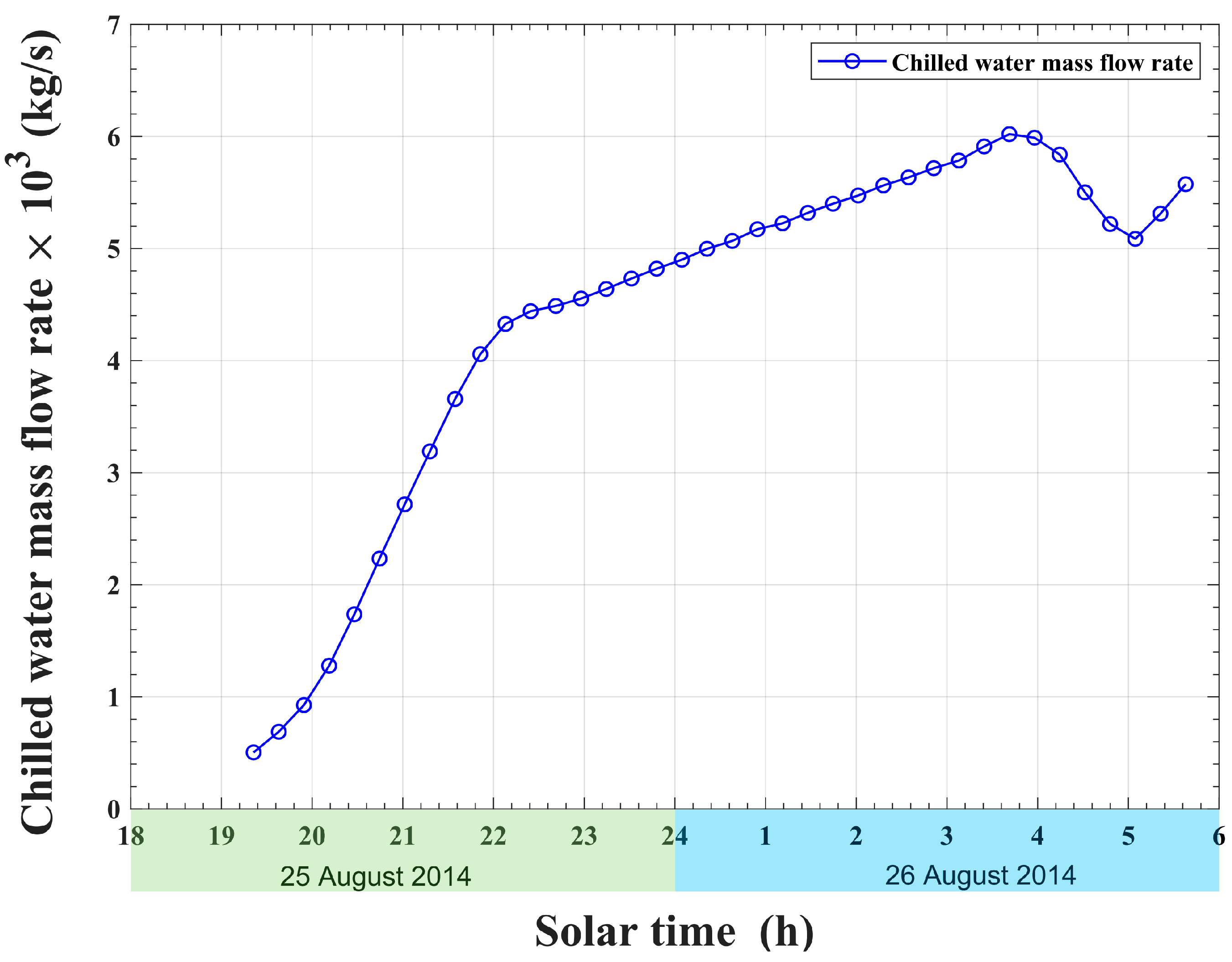
In addition to the electric power produced by the air turbine of the solar chimney power plant, the system-integrated solid-sorption water chiller produces cold water, as shown in
Figure 13. The operation of the water chiller takes place in parallel with the reactor adsorption process. The water enters the chiller at a temperature of 30 °C and exits at an evaporator temperature of 10 °C. It is found that the total chilled water produced by the system during the cycle is
(
Figure 13). Furthermore, the adsorption chiller attains a coefficient of performance of 0.455 and a specific cooling power of 5.4 W/kg of silica gel.
4. Conclusions
The solar chimney power plant is one of the systems that are driven by a low-quality thermal energy source, such as solar energy, and produce electricity. This system is simple in technology and has a low maintenance cost. The conventional solar chimney power production system comprises a large solar collector with a chimney at its center and an air turbine installed at the chimney inlet. Without thermal energy storage, the solar chimney power plant operates only during the daytime and stops working after sunset. Many hybrid solar chimney power production systems have been studied by other researchers, including photovoltaics, desalination, waste heat recovery, and others. Nonetheless, the adsorption cooling integration with the solar chimney power plant is not found in the literature.
The present paper introduces a novel hybrid solar chimney power and adsorption cold production system. The description of the proposed system, the dynamic mathematical model, and the system analysis are discussed. In this system, an adsorption reactor is integrated inside the solar collector of the solar chimney power plant. One of the striking advantages of the proposed hybrid integrated system is the recovery and recycling of the thermal energy released from the adsorption reactor during the isochoric cooling and isobaric adsorption processes. Instead of wasting this energy in the surrounding environment, it is reused to create additional draft in the chimney and produce more power from the air turbine. Another prominent advantage is the continuous power production from the turbine, which extends until the end of the cycle. It has been found that about 62.6% of the total thermal energy transferred to the adsorption bed can be recycled. The recycled thermal energy results in an additional power output from the turbine at 3.22% of the total turbine power. This additional turbine power is produced between sunset and the end of the cycle. Furthermore, it has been found that the total electric power produced by the air turbine per operating cycle is 87.74 MWh. The calculated solar-to-electricity conversion efficiency is found to be 0.4%. Furthermore, the proposed system produces a total chilled water of . The coefficient of performance of the adsorption chiller is found to be 0.455, and the specific cooling power is determined to be 5.4 W/kg of silica gel.
It is obvious that the proposed hybrid system provides continuous power throughout the day. Based on the obtained results, after sunset, the amount of the system’s power output is small, compared with the daytime power output. This puts a limitation on the system’s functional operation after sunset. In order to avoid this limitation, the system power output after sunset has to be augmented. This can be achieved through various methods. One method is to increase the amount of the adsorption reactor’s released heat by increasing its size. Another way is to merge a thermal storage material with the proposed hybrid system. The dependence of the proposed hybrid power/cooling system on the variations of climatic conditions is another limitation. The operation and functionality of the system change with variations in solar radiation, wind speed, and ambient temperature. For instance, on a cloudy day, when the solar radiation is not enough to activate the adsorption reactor, the adsorption cooling thermodynamic cycle will not be completed, and there will be no cooling effect at the chiller evaporator. Therefore, further work is required to obtain the optimum geometric design, which corresponds to the given climatic conditions. Moreover, further theoretical and experimental research work is still required to improve the output power and reduce the system thermal losses. In future work, the system’s sensitivity to the variation of its parameters will be studied to determine the operational limitations and the optimum design parameters of the system. Furthermore, merging the proposed system with other applications, such as desalination and thermal energy storage, will be investigated.


