Rate-Based Modeling and Assessment of an Amine-Based Acid Gas Removal Process through a Comprehensive Solvent Selection Procedure


Abstract
:
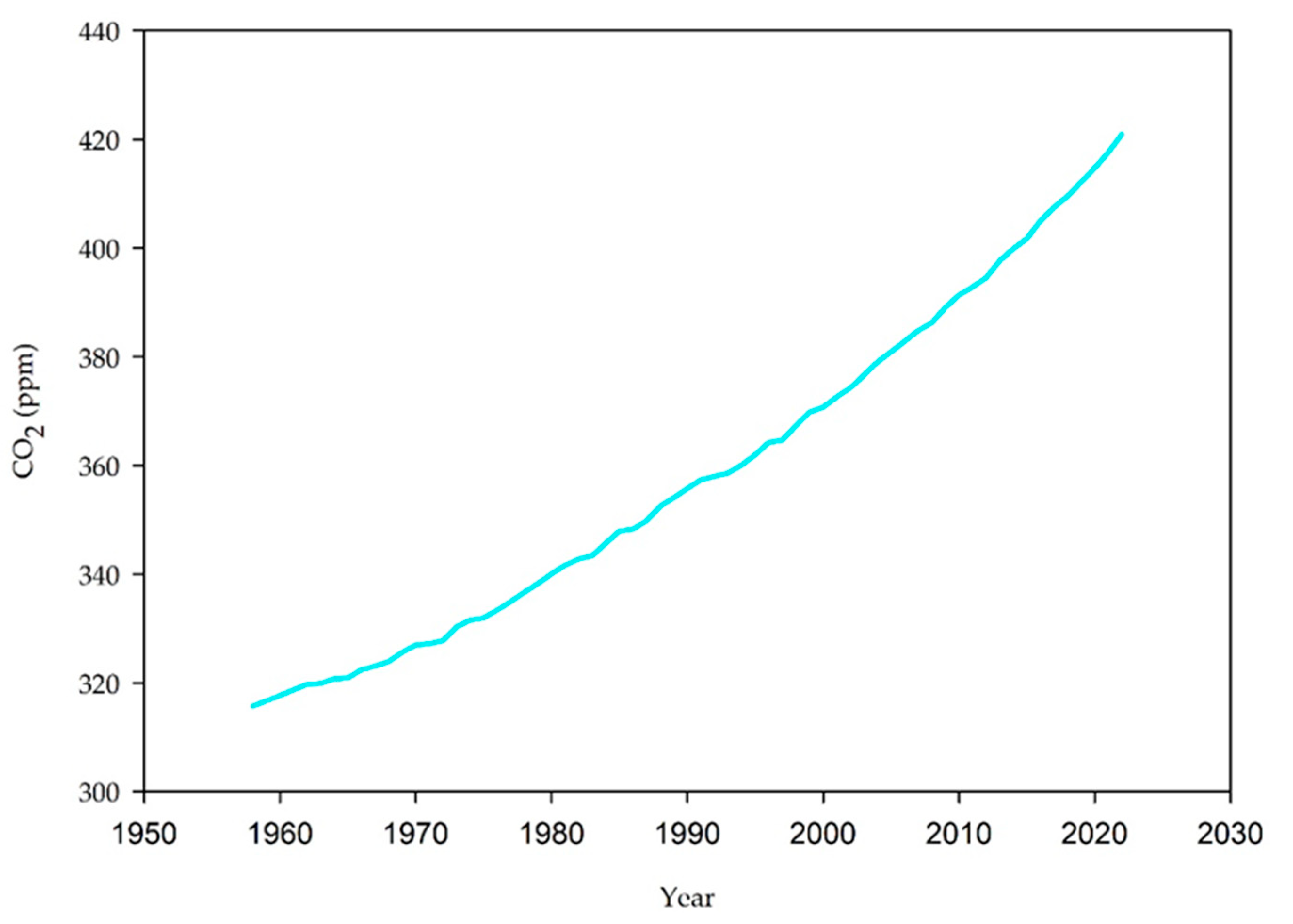
1. Introduction
2. Methods
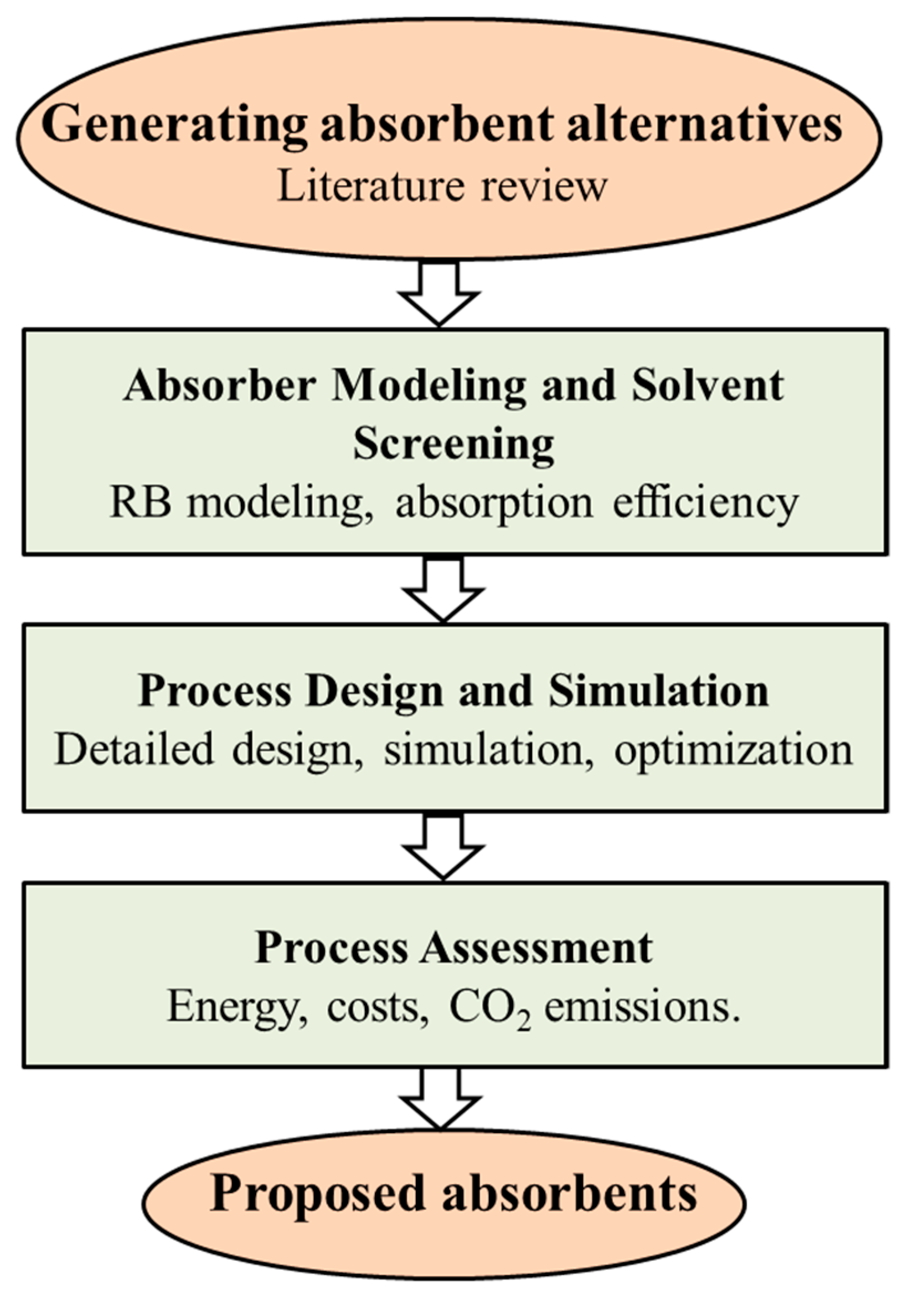
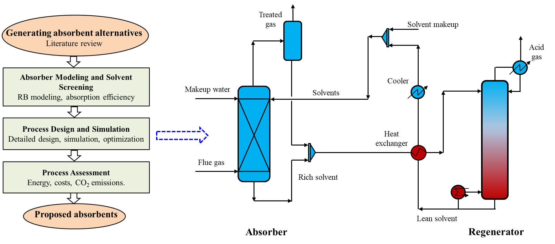
2.1. Systematic Procedure for Absorbent Selection
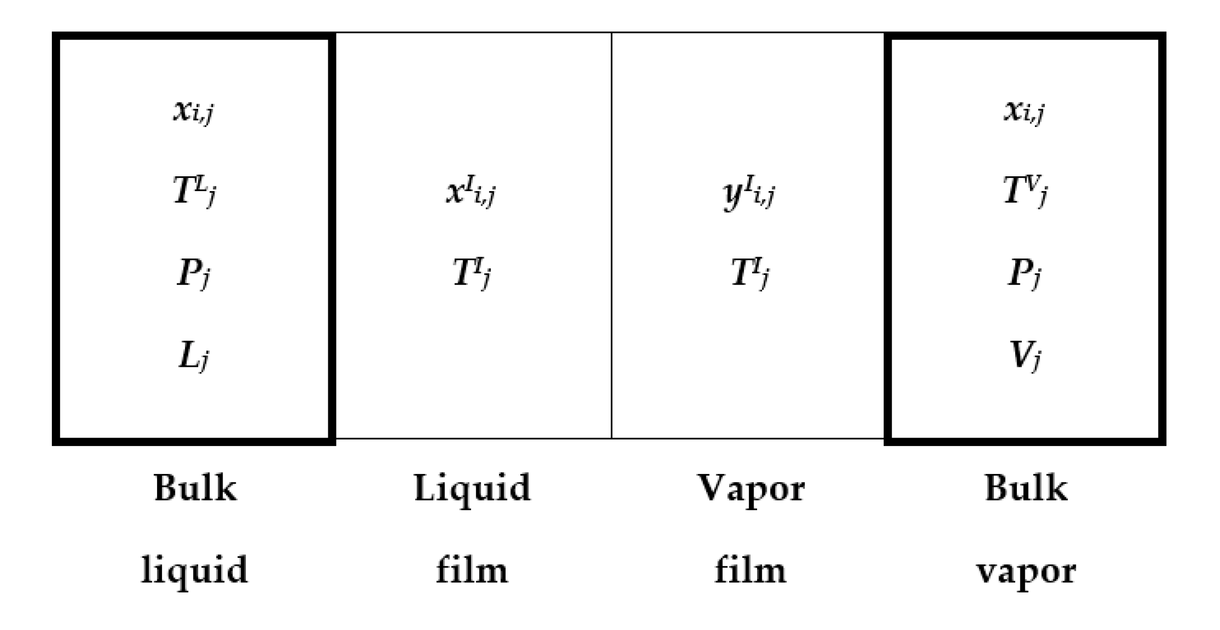
2.2. Design and Simulation
2.3. Reactions and Kinetics
2.4. Techno-Economic and Environmental Assessment
3. Results and Discussions
3.1. Generating Absorbent Alternatives
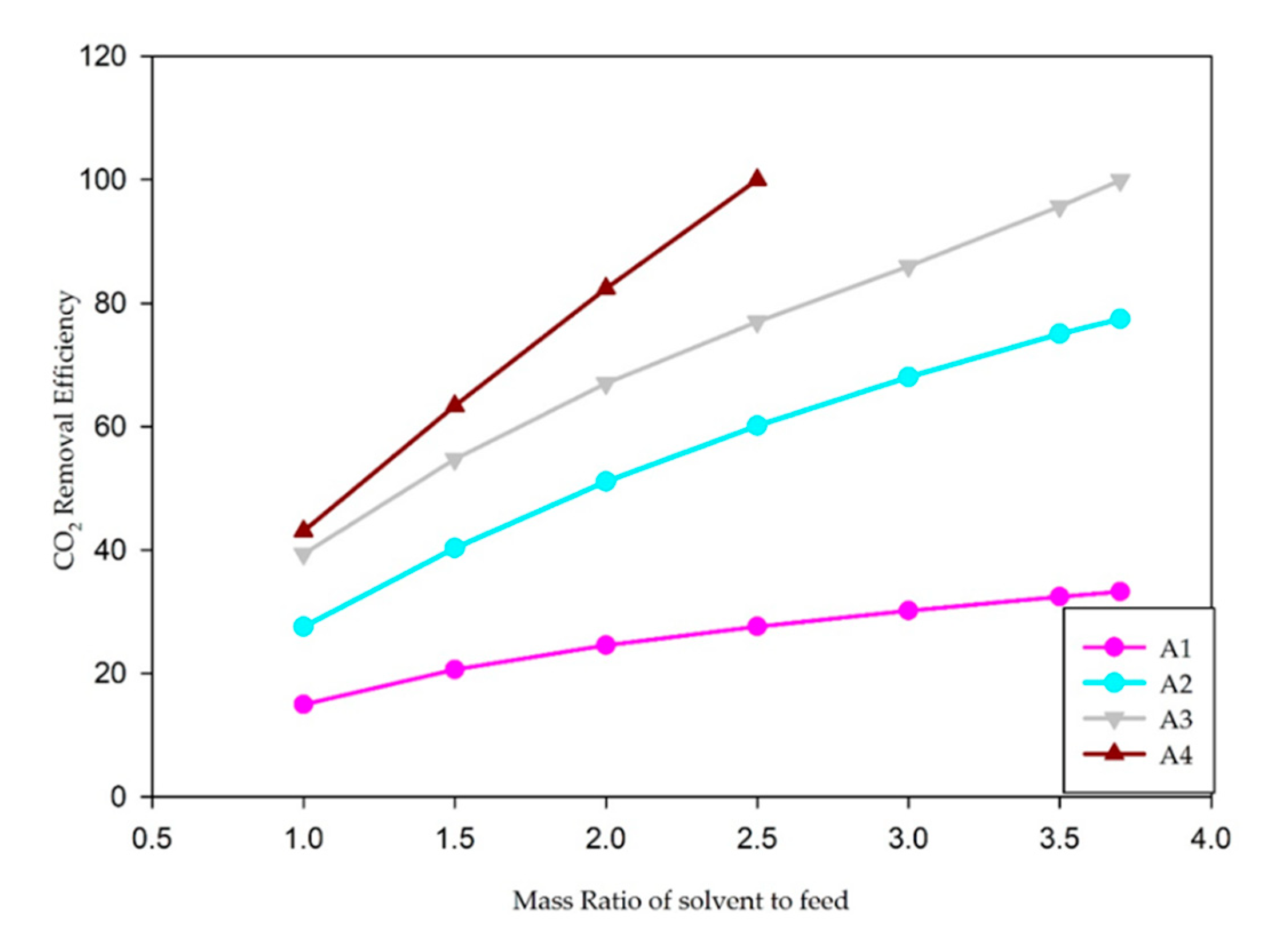
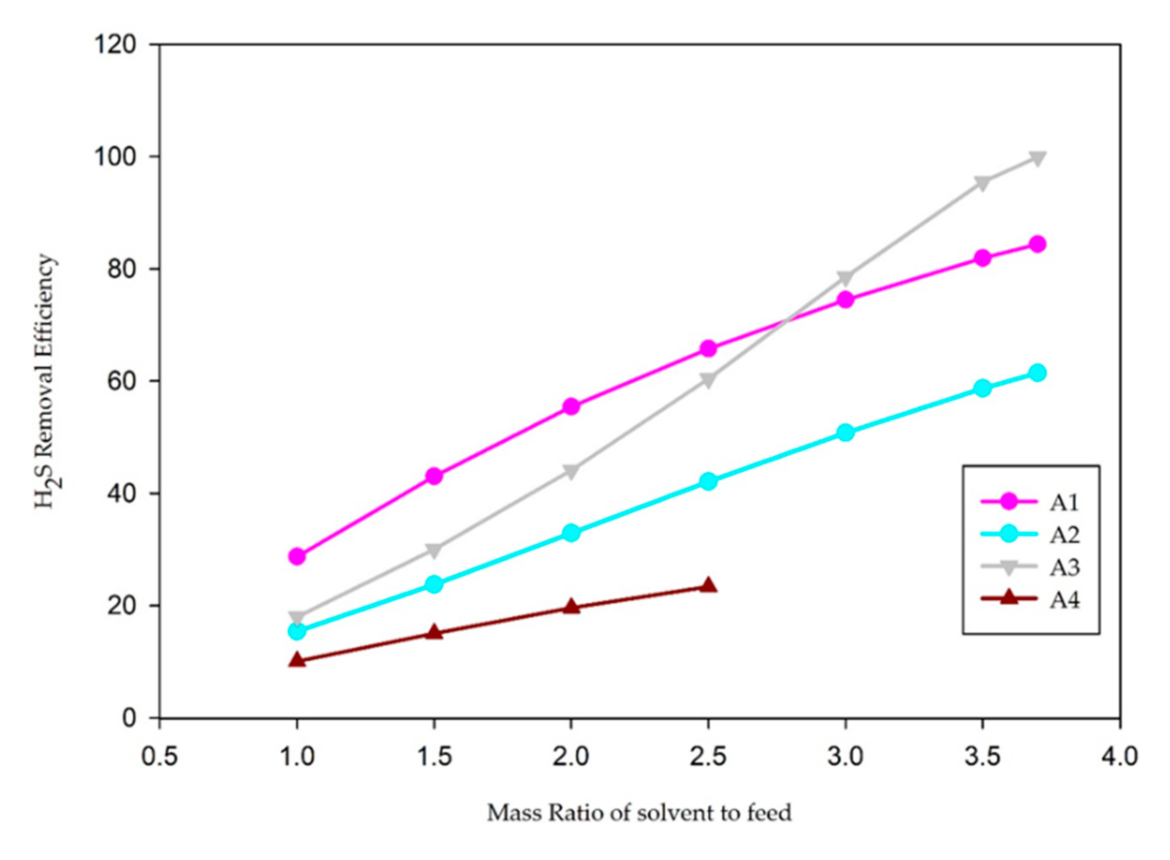
- A1: Single-amine MDEA solution (30 wt% MDEA, 70 wt% H2O);
- A2: Blends of MDEA and DEA solutions (15 wt% MDEA, 15 wt% DEA, and 70 wt% H2O);
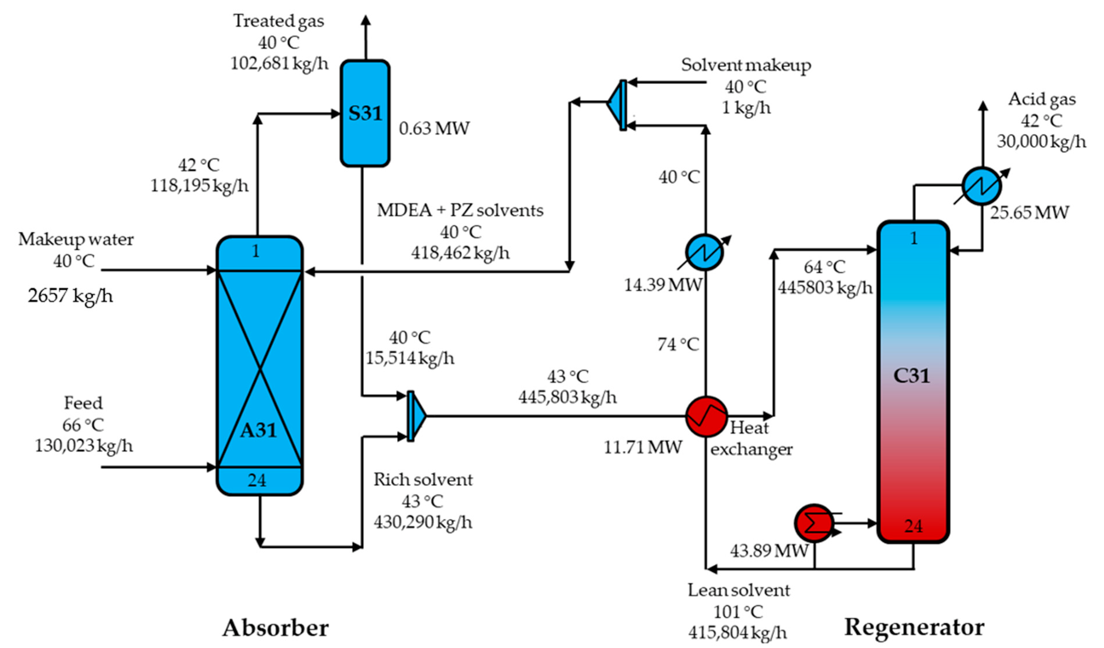
- A3: Blends of MDEA and PZ solutions (15 wt% MDEA, 15 wt% PZ, and 70 wt% H2O);
- A4: Blends of MDEA and MEA solutions (15 wt% MDEA, 15 wt% MEA, and 70 wt% H2O).
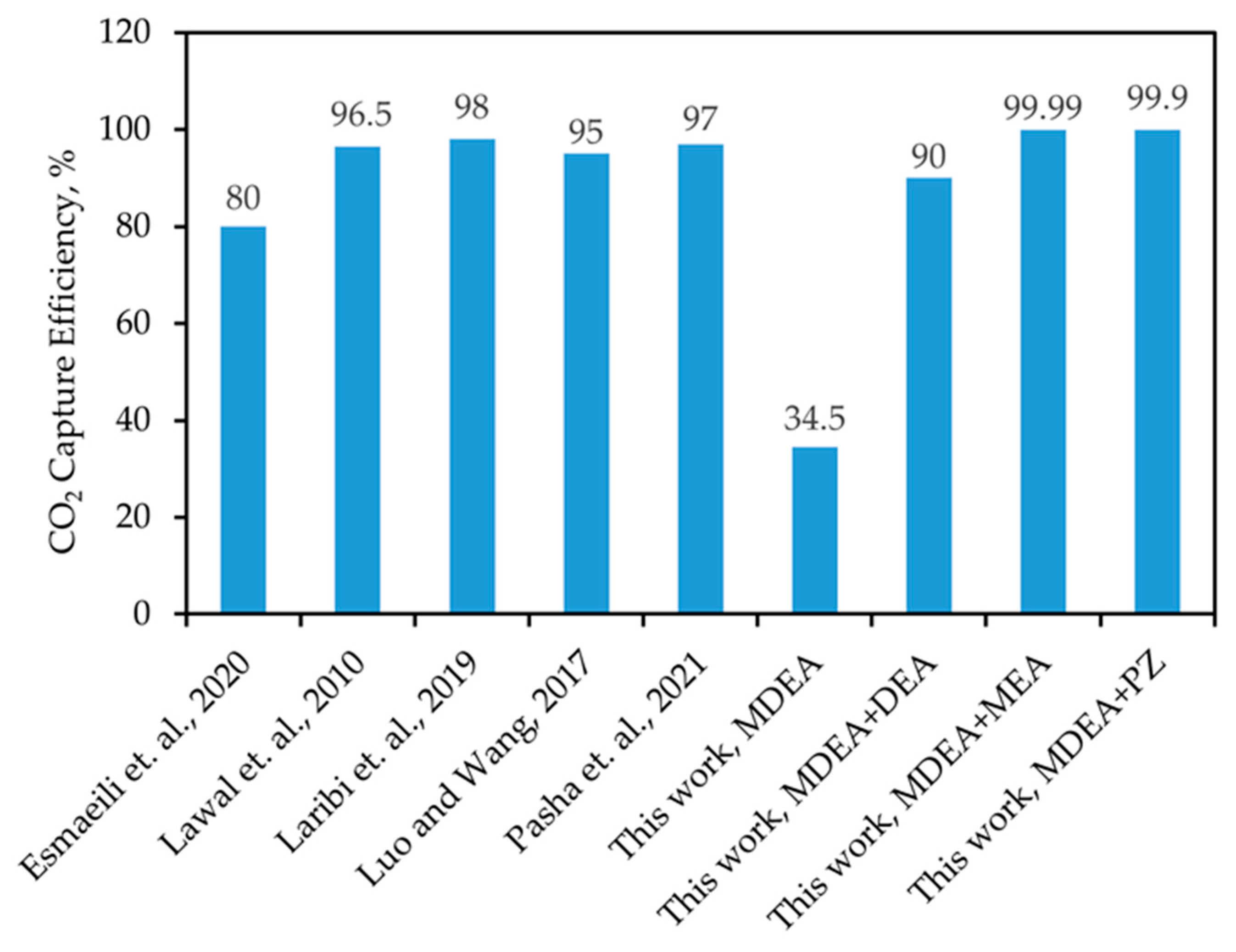
3.2. Absorber Modeling and Solvent Screening
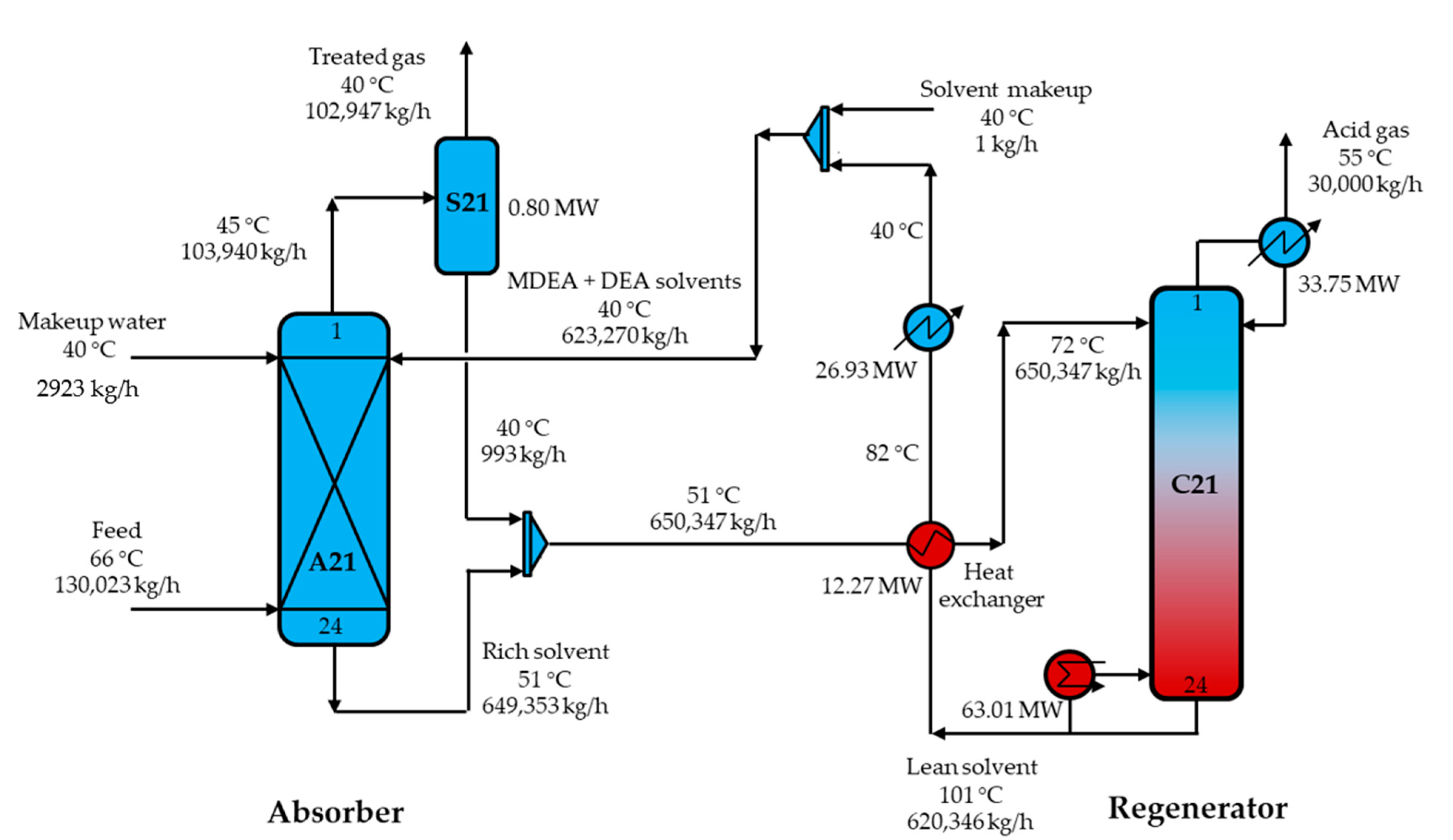
3.3. Process Design
3.3.1. MDEA-DEA Absorbent Process
3.3.2. MDEA-PZ Absorbent Process
4. Conclusions
Author Contributions
Funding
Data Availability Statement
Conflicts of Interest
References
- Masson-Delmotte, V.; Zhai, P.; Chen, Y.; Goldfarb, L.; Gomis, M.I.; Matthews, J.B.R.; Berger, S.; Huang, M.; Yelekçi, O.; Yu, R.; et al. Climate Change 2021: The Physical Science Basis Contribution of Working Group I to the Sixth Assessment Report of the Intergovernmental Panel on Climate Change; IPCC: Geneva, Switzerland, 2021; ISBN 9789291691586. [Google Scholar]
- Carbon Dioxide. Available online: https://climate.nasa.gov/vital-signs/carbon-dioxide/ (accessed on 18 April 2022).
- Carbon Capture. Available online: https://www.c2es.org/content/carbon-capture/ (accessed on 28 May 2022).
- Ishaq, H.; Ali, U.; Sher, F.; Anus, M.; Imran, M. Process analysis of improved process modifications for ammonia-based post-combustion CO2 capture. J. Environ. Chem. Eng. 2021, 9, 104928. [Google Scholar] [CrossRef]
- Ma’mun, S.; Svendsen, H.F.; Bendiyasa, I.M. Amine-based carbon dioxide absorption: Evaluation of kinetic and mass transfer parameters. J. Mech. Eng. Sci. 2018, 12, 4088–4097. [Google Scholar] [CrossRef]
- Peng, Y.; Zhao, B.; Li, L. Advance in Post-Combustion CO2 Capture with Alkaline Solution: A Brief Review. Energy Procedia 2012, 14, 1515–1522. [Google Scholar] [CrossRef]
- Borhani, T.N.G.; Akbari, V.; Afkhamipour, M.; Hamid, M.K.A.; Manan, Z.A. Comparison of equilibrium and non-equilibrium models of a tray column for post-combustion CO2 capture using DEA-promoted potassium carbonate solution. Chem. Eng. Sci. 2015, 122, 291–298. [Google Scholar] [CrossRef]
- Hospital-Benito, D.; Lemus, J.; Moya, C.; Santiago, R.; Ferro, V.R.; Palomar, J. Techno-economic feasibility of ionic liquids-based CO2 chemical capture processes. Chem. Eng. J. 2021, 407, 127196. [Google Scholar] [CrossRef]
- Fu, K.; Liu, C.; Wang, L.; Huang, X.; Fu, D. Performance and mechanism of CO2 absorption in 2-ethylhexan-1-amine + glyme non-aqueous solutions. Energy 2021, 220, 119735. [Google Scholar] [CrossRef]
- Jung, W.; Lee, J. Thermodynamic and kinetic modeling of a novel polyamine-based solvent for energy-efficient CO2 capture with energy analysis. Energy 2022, 239, 122347. [Google Scholar] [CrossRef]
- Jung, W.; Kim, E.; Lee, J.; Lee, K.S. Design of a water wash column in the CO2 capture process using a polyamine-based water-lean solvent. J. Nat. Gas Sci. Eng. 2021, 95, 104204. [Google Scholar] [CrossRef]
- Moioli, S.; Pellegrini, L.A.; Picutti, B.; Vergani, P. Improved rate-based modeling of H2S and CO2 removal by methyldiethanolamine scrubbing. Ind. Eng. Chem. Res. 2013, 52, 2056–2065. [Google Scholar] [CrossRef]
- Sheng, M.; Xie, C.; Zeng, X.; Sun, B.; Zhang, L.; Chu, G.; Luo, Y.; Chen, J.F.; Zou, H. Intensification of CO2 capture using aqueous diethylenetriamine (DETA) solution from simulated flue gas in a rotating packed bed. Fuel 2018, 234, 1518–1527. [Google Scholar] [CrossRef]
- El Hadri, N.; Quang, D.V.; Goetheer, E.L.V.; Abu Zahra, M.R.M. Aqueous amine solution characterization for post-combustion CO2 capture process. Appl. Energy 2017, 185, 1433–1449. [Google Scholar] [CrossRef]
- Esmaeili, A.; Liu, Z.; Xiang, Y.; Yun, J.; Shao, L. Simulation and validation of carbon dioxide removal from the ethane stream in the south pars phase 19 gas plant by different amine solutions using rate-based model. J. Nat. Gas Sci. Eng. 2021, 93, 104030. [Google Scholar] [CrossRef]
- Kalatjari, H.R.; Haghtalab, A.; Nasr, M.R.J.; Heydarinasab, A. Experimental, simulation and thermodynamic modeling of an acid gas removal pilot plant for CO2 capturing by mono-ethanol amine solution. J. Nat. Gas Sci. Eng. 2019, 72, 103001. [Google Scholar] [CrossRef]
- Rivera-Tinoco, R.; Bouallou, C. Comparison of absorption rates and absorption capacity of ammonia solvents with MEA and MDEA aqueous blends for CO2 capture. J. Clean. Prod. 2010, 18, 875–880. [Google Scholar] [CrossRef]
- Fang, M.; Zhu, D. Chemical Absorption. In Handbook of Climate Change Mitigation and Adaptation; Springer: New York, NY, USA, 2015; pp. 1–109. [Google Scholar]
- Seader, J.D.; Henley, E.J.; Roper, D.K. Separations Process Principles. Chemical and Biochemical Operations, 3rd ed.; John Wiley & Son, Inc.: New York, NY, USA, 2011; ISBN 9780470481837. [Google Scholar]
- Ross Taylor, R.K. Multicomponent Mass Transfer; Wiley: New York, NY, USA, 1993; ISBN 978-0-471-57417-0. [Google Scholar]
- Kenig, E.Y.; Schneider, R.; Górak, A. Reactive absorption: Optimal process design via optimal modelling. Chem. Eng. Sci. 2001, 56, 343–350. [Google Scholar] [CrossRef]
- Krishnamurthy, R.; Taylor, R. Absorber simulation and design using a nonequilibrium stage model. Can. J. Chem. Eng. 1986, 64, 96–105. [Google Scholar] [CrossRef]
- Zhang, Y.; Chen, C.C. Modeling CO2 absorption and desorption by aqueous monoethanolamine solution with Aspen rate-based model. Energy Procedia 2013, 37, 1584–1596. [Google Scholar] [CrossRef]
- Esmaeili, A.; Liu, Z.; Xiang, Y.; Yun, J.; Shao, L. Modeling and validation of carbon dioxide absorption in aqueous solution of piperazine + methyldiethanolamine by PC-SAFT and e-NRTL models in a packed bed pilot plant: Study of kinetics and thermodynamics. Process Saf. Environ. Prot. 2020, 141, 95–109. [Google Scholar] [CrossRef]
- Salvinder, K.M.S.; Zabiri, H.; Isa, F.; Taqvi, S.A.; Roslan, M.A.H.; Shariff, A.M. Dynamic modelling, simulation and basic control of CO2 absorption based on high pressure pilot plant for natural gas treatment. Int. J. Greenh. Gas Control 2018, 70, 164–177. [Google Scholar] [CrossRef]
- Zhang, Y.; Chen, H.; Chen, C.C.; Plaza, J.M.; Dugas, R.; Rochelle, G.T. Rate-based process modeling study of CO2 Capture with aqueous monoethanolamine solution. Ind. Eng. Chem. Res. 2009, 48, 9233–9246. [Google Scholar] [CrossRef]
- Zhang, Y.; Chen, C.C. Thermodynamic modeling for CO2 absorption in aqueous MDEA solution with electrolyte NRTL model. Ind. Eng. Chem. Res. 2011, 50, 163–175. [Google Scholar] [CrossRef]
- Zhao, B.; Liu, F.; Cui, Z.; Liu, C.; Yue, H.; Tang, S.; Liu, Y.; Lu, H.; Liang, B. Enhancing the energetic efficiency of MDEA/PZ-based CO2 capture technology for a 650 MW power plant: Process improvement. Appl. Energy 2017, 185, 362–375. [Google Scholar] [CrossRef]
- Sharif, M.; Zhang, T.; Wu, X.; Yu, Y.; Zhang, Z. Evaluation of CO2 absorption performance by molecular dynamic simulation for mixed secondary and tertiary amines. Int. J. Greenh. Gas Control 2020, 97, 103059. [Google Scholar] [CrossRef]
- Wang, C.; Liu, Y.; Guo, Y.; Ma, L.; Liu, Y.; Zhou, C.; Yu, X.; Zhao, G. Lead-free sodium bismuth halide Cs2NaBiX6 double perovskite nanocrystals with highly efficient photoluminesence. Chem. Eng. J. 2020, 397, 125367. [Google Scholar] [CrossRef]
- Wang, C.; Ma, L.; Wang, S.; Zhao, G. Efficient Photoluminescence of Manganese-Doped Two-Dimensional Chiral Alloyed Perovskites. J. Phys. Chem. Lett. 2021, 12, 12129–12134. [Google Scholar] [CrossRef] [PubMed]
- Nhien, L.C.; Long, N.V.D.; Kim, S.; Lee, M. Design and optimization of intensified biorefinery process for furfural production through a systematic procedure. Biochem. Eng. J. 2016, 116, 166–175. [Google Scholar] [CrossRef]
- Biegler, L.T.; Grossmann, I.E.; Westerberg, A.W. Systematic Methods of Chemical Process Design; Prentice Hall Inc.: Hoboken, NJ, USA, 1997. [Google Scholar]
- Turton, R.; Bailie, R.C.; Whiting, W.B.; Shaeiwitz, J.A.; Bhattacharyya, D. Analysis, Synthesis, and Design of Chemical Processes, 4th ed.; Prentice Hall: Hoboken, NJ, USA, 2016. [Google Scholar]
- Gadalla, M.A.; Olujic, Z.; Jansens, P.J.; Jobson, M.; Smith, R. Reducing CO2 emissions and energy consumption of heat-integrated distillation systems. Environ. Sci. Technol. 2005, 39, 6860–6870. [Google Scholar] [CrossRef] [PubMed]
- Moioli, S.; Pellegrini, L.A. Modeling the methyldiethanolamine-piperazine scrubbing system for CO2 removal: Thermodynamic analysis. Front. Chem. Sci. Eng. 2016, 10, 162–175. [Google Scholar] [CrossRef]
- Abdul Manaf, N.; Cousins, A.; Feron, P.; Abbas, A. Dynamic modelling, identification and preliminary control analysis of an amine-based post-combustion CO2 capture pilot plant. J. Clean. Prod. 2016, 113, 635–653. [Google Scholar] [CrossRef]
- Prentza, L.; Koronaki, I.P.; Nitsas, M.T. Investigating the performance and thermodynamic efficiency of CO2 reactive absorption—A solvent comparison study. Therm. Sci. Eng. Prog. 2018, 7, 33–44. [Google Scholar] [CrossRef]
- Nhien, L.C.; Long, N.V.D.; Kim, S.; Lee, M. Design and Assessment of Hybrid Purification Processes through a Systematic Solvent Screening for the Production of Levulinic Acid from Lignocellulosic Biomass. Ind. Eng. Chem. Res. 2016, 55, 5180–5189. [Google Scholar] [CrossRef]
- Lawal, A.; Wang, M.; Stephenson, P.; Koumpouras, G.; Yeung, H. Dynamic modelling and analysis of post-combustion CO2 chemical absorption process for coal-fired power plants. Fuel 2010, 89, 2791–2801. [Google Scholar] [CrossRef]
- Laribi, S.; Dubois, L.; De Weireld, G.; Thomas, D. Study of the post-combustion CO2 capture process by absorption-regeneration using amine solvents applied to cement plant flue gases with high CO2 contents. Int. J. Greenh. Gas Control 2019, 90, 102799. [Google Scholar] [CrossRef]
- Luo, X.; Wang, M. Improving Prediction Accuracy of a Rate-Based Model of an MEA-Based Carbon Capture Process for Large-Scale Commercial Deployment. Engineering 2017, 3, 232–243. [Google Scholar] [CrossRef]
- Pasha, M.; Li, G.; Shang, M.; Liu, S.; Su, Y. Mass transfer and kinetic characteristics for CO2 absorption in microstructured reactors using an aqueous mixed amine. Sep. Purif. Technol. 2021, 274, 118987. [Google Scholar] [CrossRef]

| No. | Reactions | Reaction Rate | Activation Energy J/kmol |
|---|---|---|---|
| 1 | 4.32 × 10¹³ | 5.55 × 10⁷ | |
| 2 | 2.38 × 10¹⁷ | 1.23 × 10⁸ | |
| 3 | 2.22 × 10⁷ | 3.78 × 10⁷ | |
| 4 | 1.06 × 10¹⁶ | 1.06 × 10⁸ | |
| 5 | 6.48 × 10¹⁶ | 2.12 × 10⁷ | |
| 6 | 1.43 × 10¹⁷ | 4.81 × 10⁷ | |
| 7 | 9.77 × 10¹⁰ | 4.13 × 10⁷ | |
| 8 | 2.08 × 10¹⁸ | 5.92 × 10⁷ | |
| 9 | 4.14 × 10¹⁰ | 3.36 × 10⁷ | |
| 10 | 7.94 × 10²¹ | 6.59 × 10⁷ | |
| 11 | 3.62 × 10¹⁰ | 3.36 × 10⁷ | |
| 12 | 5.56 × 1025 | 7.68 × 10⁷ |
| Component | Mass Fraction (wt%) |
|---|---|
| H2O | 2.40 |
| CO2 | 19.35 |
| H2S | 5.67 |
| N2 | 72.58 |
| Temperature (°C) | 66 |
| Pressure (bar) | 1.2 |
| Mass flowrate (kg/h) | 130,023 |
| Absorbents | Formula | Molecular Structures | Amine Type | CAS Number |
|---|---|---|---|---|
| N-Methyldiethanolamine (MDEA) | C5H13O2N | 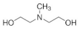 | Tertiary alkanolamine | 105-59-9 |
| Diethanolamine (DEA) | C4H11O2N | 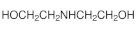 | Secondary alkanolamine | 111-42-2 |
| Piperazine (PZ) | C4H10N2 | 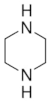 | Cyclical diamine | 110-85-0 |
| Monoethanolamine (MEA) | C2H7ON |  | Primary alkanolamine | 141-43-5 |
| Case | Feed/Solvent Ratio (Mass) | CO2 Removal Efficiency (wt%) | H2S Removal Efficiency (wt%) |
|---|---|---|---|
| A1 (30 wt% MDEA) | 1:1 | 15.0% | 28.7% |
| 1:1.5 | 20.6% | 43.0% | |
| 1:2 | 24.6% | 55.4% | |
| 1:2.5 | 27.6% | 65.8% | |
| 1:3 | 30.2% | 74.5% | |
| 1:3.5 | 32.4% | 81.9% | |
| 1:4 | 34.5% | 88.5% | |
| A2 (15 wt% MDEA + 15 wt% DEA) | 1:1 | 27.5% | 15.4% |
| 1:1.5 | 40.3% | 23.8% | |
| 1:2 | 51.1% | 32.9% | |
| 1:2.5 | 60.1% | 42.1% | |
| 1:3 | 68.0% | 50.8% | |
| 1:3.5 | 75.0% | 58.7% | |
| 1:4 | 81.3% | 65.8% | |
| A3 (15 wt% MDEA + 15 wt% PZ) | 1:1 | 39.4% | 18.0% |
| 1:1.5 | 54.8% | 30.0% | |
| 1:2 | 67.0% | 44.1% | |
| 1:2.5 | 77.0% | 60.4% | |
| 1:3 | 86.0% | 78.6% | |
| 1:3.5 | 95.7% | 95.5% | |
| 1:4 | 99.9% | 99.9% | |
| A4 (15 wt% MDEA + 15 wt% MEA) | 1:1 | 43.0% | 10.1% |
| 1:1.5 | 63.4% | 15.0% | |
| 1:2 | 82.4% | 19.6% | |
| 1:2.5 | 100.0% | 23.4% |
| Structural Alternative | A2 (MDEA + DEA) | A3 (MDEA + PZ) |
|---|---|---|
| Reboiler duties (MW) | 63.01 | 43.89 |
| Reboiler duty savings | 30.3% | |
| Condenser duties (MW) | 68.68 | 40.69 |
| Condenser duty savings | 40.8% | |
| TIC (US k$) | 12,451 | 11,194 |
| TIC savings | 10.1% | |
| TOC (US k$/year) | 26,009 | 18,093 |
| TOC savings | 30.4% | |
| TAC (US k$/year) | 27,865 | 19,761 |
| TAC savings | 29.1% | |
| TCE (ton/year) | 128,528 | 89,527 |
| TCE reduction | 30.3% |
Publisher’s Note: MDPI stays neutral with regard to jurisdictional claims in published maps and institutional affiliations. |
© 2022 by the authors. Licensee MDPI, Basel, Switzerland. This article is an open access article distributed under the terms and conditions of the Creative Commons Attribution (CC BY) license (https://creativecommons.org/licenses/by/4.0/).
Share and Cite
Agarwal, N.; Cao Nhien, L.; Lee, M. Rate-Based Modeling and Assessment of an Amine-Based Acid Gas Removal Process through a Comprehensive Solvent Selection Procedure. Energies 2022, 15, 6817. https://doi.org/10.3390/en15186817
Agarwal N, Cao Nhien L, Lee M. Rate-Based Modeling and Assessment of an Amine-Based Acid Gas Removal Process through a Comprehensive Solvent Selection Procedure. Energies. 2022; 15(18):6817. https://doi.org/10.3390/en15186817
Chicago/Turabian StyleAgarwal, Neha, Le Cao Nhien, and Moonyong Lee. 2022. "Rate-Based Modeling and Assessment of an Amine-Based Acid Gas Removal Process through a Comprehensive Solvent Selection Procedure" Energies 15, no. 18: 6817. https://doi.org/10.3390/en15186817
APA StyleAgarwal, N., Cao Nhien, L., & Lee, M. (2022). Rate-Based Modeling and Assessment of an Amine-Based Acid Gas Removal Process through a Comprehensive Solvent Selection Procedure. Energies, 15(18), 6817. https://doi.org/10.3390/en15186817