Review

Liquid–Gas Jet Pump: A Review

College of Metrology & Measurement Engineering, China Jiliang University, Hangzhou 310018, China
*
Authors to whom correspondence should be addressed.
Energies 2022, 15(19), 6978; https://doi.org/10.3390/en15196978
Submission received: 3 September 2022 / Revised: 14 September 2022 / Accepted: 19 September 2022 / Published: 23 September 2022
(This article belongs to the Section K: State-of-the-Art Energy Related Technologies)

Abstract

:
To promote the development and application of the liquid–gas jet pump (LGJP), the research status of its design theory, internal flow mechanism, structural optimization and practical application are reviewed. The development history of the LGJP is briefly reviewed, the latest research and application progress of the LGJP is introduced, and the pulse-type of LGJP, especially the centrifugal jet vacuum pump (CJVP), is emphatically discussed. The research and development direction of the LGJP is analyzed and proposed: CFD will be more deeply applied to the mechanism research and performance improvement of the LGJP; the diversity and heterogeneity of the fluid medium and its influence on the internal flow mechanism are the research highlights of the LGJP; it is urgent to study the gas–liquid two-phase flow and pumping mechanism inside the pulsed liquid–gas jet pump (PLGJP), especially the CJVP.

1. Introduction

The liquid–gas jet pump (LGJP) is a kind of fluid conveying machinery and mixing reaction equipment, utilizing high-speed working liquid ejected from the nozzle to transfer energy to pumped gas through momentum exchange [1,2,3]. It has the advantages of a simple structure, easy processing, simple installation, good sealing, no moving parts and easy maintenance and is widely used, especially under various special working conditions such as high temperature, high pressure, vacuum and underwater [4,5,6,7,8,9]. However, the low energy transfer efficiency of the LGJP is not conducive to its further promotion and use. Therefore, a current focus of research is on how to keep the LGJP running efficiently under different applications [10,11]. At the same time, a change in operating conditions will also affect the performance of the LGJP, so improving its adaptability to operating conditions has also attracted more attention from scholars [12,13,14]. Scholars have carried out a lot of work on the LGJP using theoretical analysis, experimental research and computational fluid dynamics (CFD) technology to explore its internal two-phase flow and gas suction mechanism in an attempt to fundamentally solve these problems [15,16,17,18]. Summarizing these research results and methods can provide the basis and reference for further research on the LGJP.

2. Structure and Principle

The LGJP is mainly composed of four parts: the nozzle, the mixing chamber, the throat and the diffuser (see Figure 1). When the working fluid (liquid) is spewed out at high speed from the nozzle, the gas around it is sucked to form negative pressure in the mixing chamber, and the suction gas is sucked in. The two fluids are then mixed in the throat and exchange momentum, so that the velocity of the working fluid decreases and the velocity of the sucked gas increases. At the outlet of the throat, the velocities of the two fluids are basically the same. The velocity of the mixed fluid in the diffuser gradually decreases while the pressure gradually increases, converting kinetic energy into pressure energy.
The liquid and gas in the mixing chamber have different velocities, and when the two are mixed, a large energy loss occurs, which reduces the efficiency of the LGJP. At present, the methods to improve the mixing efficiency mainly include structural optimization [5,7,8,9] and the use of pulsed jets [19], that is, a pulsed liquid–gas jet pump (PLGJP). There are two main ways of pulse generation: one is to install the pulse generator at the front of the nozzle without changing the original liquid–gas jet pump structure, so that the working liquid has a certain pulse frequency [18]; the other is the centrifugal jet vacuum pump [9] (CJVP).
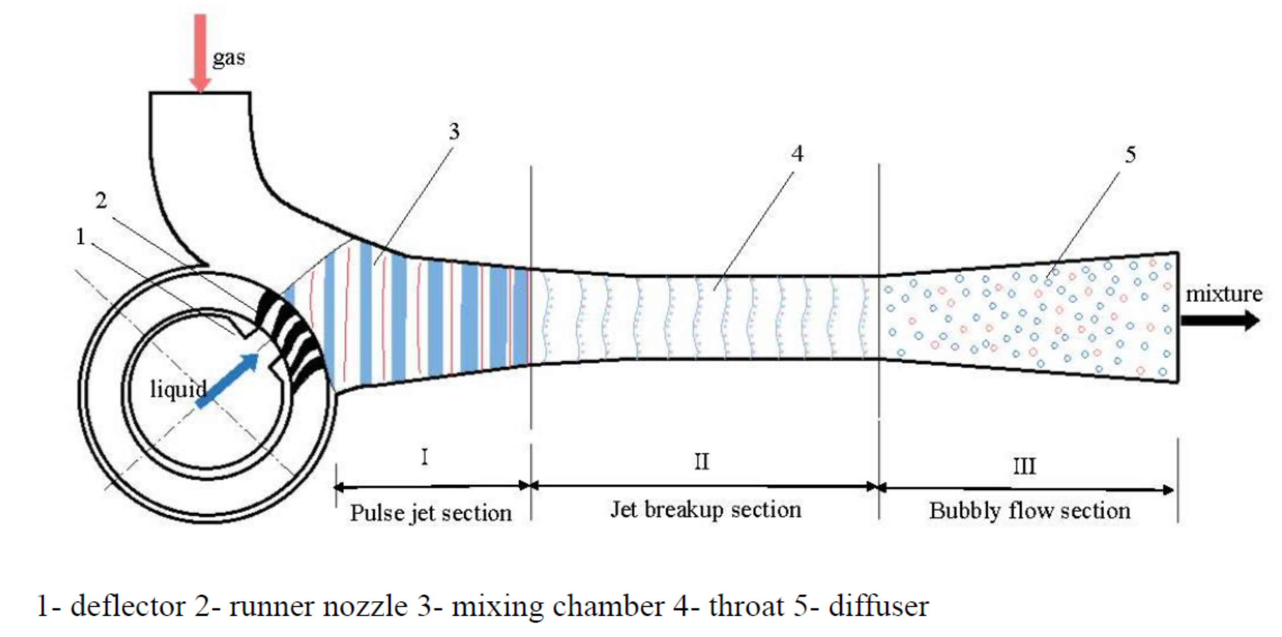
The CJVP adopts the structure of the runner nozzle and the deflector on the basis of retaining the LGJP mixing chamber, throat, diffuser and other structures (see Figure 2). Only when the runner nozzle communicates with the deflector and the mixing chamber can the working fluid be thrown out into the mixing chamber through the runner nozzle, and the connection time of each runner nozzle is limited, thereby generating a pulsed jet.
Pulse jets can rapidly mix fluids, thereby reducing the length of the mixing section. The PLGJP has good suction performance because the inertial force of the pulse jet increases the working pressure of the jet pump, thereby improving the suction capacity. There are two ways for the pulsed jet to carry the gas into the suction chamber: one is the viscous effect between the fluids, and the other is that the gap between the pulsed jets ejected from the nozzle plays the role of the piston pump. The pulse frequency generated by a pulse generator is usually less than 10 Hz [9], while the pulse frequency generated by a CJVP can reach more than 1000 Hz, so it has higher suction capacity and efficiency.

3. Research Status

3.1. Research Status of the LGJP

Jet pump design theory has been studied for more than 150 years. As early as the 1860s, the German scholar Zeune [1] established the theoretical basis of jet pump design according to the momentum theorem. Although the research of the jet pump has a long history, it was not until the 1930s that, with the continuous development of science and the continuous improvement of the knowledge system about fluid mechanics and aerodynamics, the theoretical research and practical application of the LGJP were further developed. The specific concept of the LGJP was first proposed by the scholar Hoeffer [5] in 1922 and was successfully applied in the vacuum pumping experiment of a condenser. Subsequently, a large number of research papers on the LGJP were published in various magazines. Then, through a large number of experimental studies conducted by Rammingen [2], they discovered the sudden rise in the pressure of the two-phase fluid after mixing at the throat. Then more scholars began to study the effect of changing the length of the throat on the mixing performance of the gas–liquid two-phase flow on this basis to obtain the approximate range of the optimal length. At the same time, Bonnington [6] found in the gas–liquid two-phase mixing experiment of the transparent throat that as the flow rate of the LGJP increased, the entrainment efficiency of the LGJP decreased. The gas effect was obviously improved. Within a certain length of the throat, the longer the throat, the better the entrainment effect.
Witte [1] was the first to combine the application of the Euler equation with the theoretical analysis of the LGJP and described the flow process of the two-phase fluid in the tube in detail, thereby defining the mixed shock wave. He found that the two-phase fluid in the flow mixing process showed a great influence on the compressed gas, and the structure of the LGJP was further optimized. Higgins [7] deduced the unary relationship of the drag coefficient introduced by the LGJP and verified the correctness of the theoretical derivation through experiments. The results showed that the suction performance was the best when the two-phase fluid was mixed at the throat outlet of the LGJP. Lu [8,9] derived the basic performance equation of the LGJP based on the simplified method of unitary flow, optimized some parameters, took into account the influence of different flow rates of each structural plane in the pump and verified the accuracy of the theoretical equation through experiments. On this basis, he comprehensively summarized the research results of experts and scholars at home and abroad on the jet pump. In 1989, he published a monograph on jet technology, the Theory and Application of Liquid–Gas Jet Pump Technology, and in 2004, he published again, the Theory and Application of Jet Technology. Long [10] obtained the performance equation of the LGJP under the condition of constant determination based on the relevant theories of fluid mechanics on the premise of constant determination of the basic performance equation of the LGJP, laying a foundation for further study and analysis of the internal flow mechanism of the unsteady liquid–gas jet pump.
Betzler [8] used experiments to analyze the influence of the size of the diffuser, and the results showed that the LGJP displayed better suction performance when the two-phase fluid was completely mixed before entering the diffuser. When optimizing the overall structure of the LGJP, it was found that when the length–diameter ratio of the throat was 23, the gas isothermal compression rate of the LGJP could reach about 19%. Based on a large number of experimental results, Cunningham [2] analyzed that the gas isothermal compression efficiency of the LGJP could reach 40% or even higher under optimal working conditions as long as the structural parameters of the LGJP, such as the throat length–diameter ratio and throat diameter, were given reasonable values. When Neve [7] tested the performance of the diffuser of the LGJP, he found that the performance of the diffuser was related to the degree of homogeneous mixing of the two-phase fluid in the diffuser and the inconsistency of velocity at the entrance of the diffuser.
Haidl [11] used a converging nozzle to measure the suction capacity of a conventional liquid–gas jet pump while experimenting with the performance of the pump in less stable configurations, providing the best design suggestions for units with various geometric shapes, directions and operating conditions to minimize gas entrainment. Opletal [13] studied the influence of the geometric parameters of the jet pump on the injection ratio and mass transfer coefficient, showed that the working structure parameters had an important influence on the injection performance of the LGJP and proposed a method to evaluate the mass transfer performance. Kim [14] and others simulated and analyzed that the suction rate of a LGJP was proportional to the fluid circulation velocity in the pump, but as the nozzle diameter increased, the suction volume decreased. The Rahman [12] experiment found that nozzle geometry affected the gas entrainment rate and pressure drop in the pump and that a low nozzle coefficient could form a higher vacuum in the pump. Sharma [15] designed different shapes of nozzles for experiments and analyzed and compared the performance of LGJPs of various shapes. Sung [4] compared the entrainment flow of the LGJP in three installation modes: horizontal, vertical upward and vertical downward and found that the gas entrainment rate installed vertically downward was the best. Liu [16] observed the flow process in the pump and measured the pressure distribution in the pipe through experiments. Based on the expression of American scholars, he supplemented the expression for the optimal throat length and proposed that the isothermal compression efficiency during vacuum pumping could reach 20~50% of the optimal parameter design of the LGJP. Liao [17] studied the performance of the LGJP through experiments and at the same time, used a method of numerical simulation to analyze the variation law and interaction of various parameters in the LGJP. He measured and recorded the pressure of the LGJP and flow data under different area ratios, and the influence of the area ratio on the inspiratory performance was determined by analysis. Gao [18,19] used geometric parameters and working parameters, such as nozzles with different diameters, area ratio, throat distance and pulse frequency, to test the liquid–gas piston pulse jet pump and preliminarily mastered the stable conditions of the device operation. Ge [20] proposed that when the throat-to-nozzle distance of the LGJP remained unchanged, the pressure ratio gradually decreases with the increase in the flow ratio. When the throat distance was 1.5 times the nozzle diameter, the efficiency of the LGJP was the highest, and the optimal throat distance range of the LGJP was determined to be 1.0 to 1.7 times the nozzle diameter.
Bhatkar [21] experimentally studied the performance parameters of the LGJP. The results showed that the working efficiency increased with the increase in the flow ratio and decreased with the decrease in the pressure ratio. Wu [22] conducted experiments under the same orifice Reynolds number and different liquid–gas flow ratio. The experiments showed that the bubble size in the pump was inversely proportional to the flow ratio, and the bubble diameter significantly changed at a low Reynolds number but changed little at a high Reynolds number. Eisallak [23] experimentally analyzed the influence of inlet pressure on jet flow. The results showed that the performance of LGJP was improved when the inlet pressure was weak, and the pump efficiency was reduced when the inlet pressure was strong. Mikheev [24] conducted an experimental analysis on the nozzle and capacity curve of the LGJP in the working environment where the inlet pressure was greater than 1 MPa. Zhang [25] put forward the scheme of using the LGJP to recover casing gas and emphasized that the optimal distance between the nozzle and throat of the LGJP is different under different working fluid pressures.
Carvalho [26] carried out numerical simulation research on the flow field of two-phase fluid in the throat of the LGJP with CFD software on the computer. Jiao [27] analyzed the mathematical model of the LGJP, synthesized the empirical resistance coefficients of each structure of the LGJP as a dimensionless undetermined coefficient, determined its undetermined coefficient through a large number of experiments and obtained the correlation function expression. The mathematical model of single-phase flow was extended, and the mathematical model of two-phase flow of the LGJP was determined. At the same time, the results of multiple numerical simulations showed that compared with the single-phase flow model, the mathematical model of two-phase flow was more accurate in analyzing and comparing the performance of the LGJP. Ismagilov [28] measured the performance of the LGJP and analyzed its characteristics by discussing the physics of the LGJP and establishing a mathematical model. Sharma [29] conducted a simulation analysis on the influence of the turbulent flow effect in the CFD model on the internal flow and gas entrainment rate of the LGJP to optimize the design of the pump. Zhu [30] studied the influence of the structure size on the suction performance of the LGJP and used the CFD numerical simulation method to study the relationship between the structural parameters of the nozzle area ratio, the throat, the nozzle distance, the throat length and the suction performance, respectively. Finally, the optimal range of each structure size under the highest efficiency was given. Semlitsch [31] proposed that four alternative jet pump configurations have been explored, i.e., a chevron primary nozzle, an empirical primary nozzle, a primary nozzle with swilling inserts and a multiple injector nozzle. The simulation found that, with the chevron primary nozzle, the jet pump efficiency with the chevrons slightly increased (less than one percent). Using an elliptical primary nozzle, the diffuser was only partially better utilized with an elliptical primary jet pipe exit, but an improvement of the jet pump efficiency of approximately two percent was achieved. With the primary nozzle with swirling inserts, the ratio of flow momentum to mixing could be manipulated with an increase in guide vane height to optimize the primary jet structure. The efficiency of the jet pump increased by about 6% using a multiple injector nozzle. Zheng [32] used a numerical simulation to simulate the internal flow field of the LGJP and found that with the increase in the liquid flow rate and the diameter of the diffuser outlet, the pressure dropped at the jet outlet and increased at the inlet of the jet pump accordingly. In addition, the wall flow effect increased, and the working efficiency decreased. Qin [33] pointed out that the appropriate liquid inlet speed can stabilize the volume fraction of each phase in the LGJP, which is conducive to the normal injection of the ejector. The increase in the output pressure of the diffuser leads to steam liquefaction and affects the normal operation of the ejector. Gao [34] conducted a three-dimensional numerical simulation calculation on the throat cavity contraction half angle of different LGJPs. It was found that the variation trend of the efficiency of the LGJP with the contraction half angle was similar to that of the pressure ratio, and there was a maximum value. The optimal suction efficiency interval was determined according to the reduction in the maximum suction efficiency by 5%, and the optimal range of the corresponding throat contraction half angle was 13.5°~17.1°. Wang [35] simulated the mixed flow in a LGJP and divided the mixing process into three stages: coaxial flow, mixed shock flow and bubble flow. The mixed shock wave was the main factor affecting the mixed flow characteristics and the performance of the LGJP.
Yang [36,37,38,39] designed the diffuser of the jet pump using the method of constant speed or constant pressure change, studied the influence of structural parameters on the internal flow field and found, through analysis that compared with the traditional conical diffuser, that the diffuser with constant speed or constant pressure change obtained a better performance and significantly shortened the length of the jet pump. There was an optimal combination of throat and diffuser. In order to improve the performance of an annular jet pump, the constant velocity/pressure rate of change method was used to design its diffuser, and the results showed that the prediction results of the RNG k-ε turbulence model were in better agreement with the experimental data than the standard, and this is an achievable k-ε turbulence model.
Sato [40] used high-speed camera technology to observe the whole process of cavitation generation, development and collapse in the Venturi and observed the unstable sheet-like cavitation cloud in the diffusion section under a small cavitation number. Stutz [41] observed the unstable sheet-like cavitating cloud of a Venturi tube with an X-ray device and dual light detector, found that the change in the cavitating cloud volume with time characterized the periodic law of cavitating cloud shedding and pointed out that the exit velocity had an important impact on the cavitating flow and the frequency of cavitating cloud shedding. Coutier [42,43] carried out a numerical simulation of the unstable cavitating flow in rectangular Venturi, and the obtained results are in good agreement with the test results of Stutz [41].
In order to improve the accuracy of the unsteady cavitation simulation of hydrofoil, Gu [44,45,46] used the GCI evaluation method to study grid independence and dispersion error to determine the optimal number of grids and reveal the mechanism of instability and falling off of hydrofoil cavitation. Yazici [47] studied the cavitating flow in the two-dimensional axisymmetric Venturi, found that the vibration frequency range of the cavitating flow was wide and observed that the high momentum bubbles eventually collapsed into small low momentum bubbles in the diffusion tube, and the vibration became smaller. Sayyaadi [48] observed the fluctuating process of the cavitating flow in Venturi using a high-speed camera and found that compared with the working pressure, the cavitating number had a more significant impact on the pulsating frequency, eigenfrequency and dimensionless parameter st of the length of the cavitating cloud and believed that the return jet was the main factor for cavitating cloud shedding. Xu [49] studied the influence of the area ratio of the diffuser inlet to the nozzle outlet, the volume of the displacement container and the configuration of the suction gap on the performance of the Venturi counter flow diverter pumping system. The RFD system with an area ratio greater than 1 showed a higher efficiency, and the reduction in the volume pressure around the jet core led to cavitation, which led to a reduction in the lifting efficiency.
Long [50] used high-speed camera technology to study the cavitating flow of the Venturi under three different states and analyzed the variation law of the cavitating cloud area. The results showed that after the cavitating cloud was generated from the near wall surface of the starting section of the Venturi throat, it gradually developed downstream and fell off periodically in different ways at different stages of cavitation. The falling-off of the cavitating cloud was strongly related to the pressure pulsation at three different positions in the diffuser but had little correlation with the pressure pulsation in the throat. Wang [51] conducted experiments to collect and analyze images of various cavitating flows through high-speed camera technology to study the cavity length pulsation characteristics of jet pumps with different area ratios at limited operating stages. Through experiments, Yan [52] found that there was obvious backflow in the second half of the Venturi diffusion section, which led to the periodic shedding of cavitation clouds.
Hu [53] carried out a large eddy simulation (LES) on the transient jet, and the results showed that the entrainment temporarily increased during deceleration, but the LES prediction results also provided insights into the potential hydrodynamics that led to the increase in entrainment. Xu [54,55] used a large eddy simulation method to study the coherent structure in the turbulent flow field of an annular jet pump with different area ratios. The results showed that the vortices were mainly distributed in the recirculation region and in the mixing and boundary layers, which had large velocity gradients.
The comparison between the numerical results obtained by RANS simulation and the experimental data is often limited due to the performance parameters or point measurements of the jet pump [56,57]. Some RANS simulations have been compared with experimental flow visualization [58,59]. There are different turbulence closure models such as the standard k-ε Model [8], realizable k-ε Model [55], standard k-ω Model [60] and k-ω SST model [61].
Semlitsch [62] used the LES method and the steady-state Reynolds averaged Navier– Stokes formula to study the flow field in jet pumps and compared the flow field solutions obtained by the two numerical tools. The results showed that the reasonable consistency of velocity and pressure contours could be achieved. Liang [63] used LES combined with the Zwart–Gerber–Belamri cavitation model to simulate the flow inside the Venturi under different cavitation numbers. The results showed that the V and V method based on the five-equation model could effectively reflect the error of a large eddy simulation of the flow inside the Venturi, but the consumption of computational resources is too large and needs further improvement.
Zhao [64,65] successfully removed acid substances and large dust particles in flue gas using the LGJP and determined the optimal injection ratio through experiments. It was found that the gas flow and injection ratio decreased with the increase in outlet pressure, and the gas flow and the injection ratio of the LGJP first increased and then decreased with the increase in the ratio of the throat inlet to the nozzle outlet area. Different nozzle diameters corresponded to different optimal area ratios, and there was an optimal nozzle contraction angle under the specified operating parameters. Andrii [66] studied the hydrodynamic properties of the liquid–gas mixture in different regions of the mixing chamber of the jet pump and developed a conical–cylindrical jet device for the motion characteristics of the mixture.
Combining the application of the LGJP in a seawater purification system, Kumar [67] mainly studied the influence of the distance from the nozzle to the inlet of the throat in the structural parameters of the LGJP on its suction performance and showed that the optimal distance from the nozzle to the throat inlet was 33 mm. Drozdov [68] combined the actual oil and gas production test bench to control the output pressure of the LGJP and analyzed the pressure and power characteristics. Asuaje [69] combined the LGJP with its application in the oil and gas industry, using CFD simulation and an optimization algorithm and proposed a new eccentric jet pump geometry to improve the outlet velocity and pressure field. Under the same conditions, the optimally connected eccentric jet pump was analyzed, and the performance of the treatment fluid was improved by 2%. Considering the homogeneous multiphase flow, Asfora [70] proposed a simplified model for a numerical simulation based on the LGJP used in oil production to verify the influence of the mixing state of the throat on the jet pump. Kolla [71] modified and simulated the inlet section of the LGJP based on three different applications of the LGJP and optimized the field application structure according to the simulation results. Bazaluk [72] used a computer program to calculate and analyze the working parameters of an actual production oil well and calculated the installation position and geometric shape of the LGJP in the oil production system to obtain the optimal selection to ensure the reliable operation of production. Toteff [73] combined the work of the LGJP system for the transportation of heavy oil in petroleum production, carried out an optimization and simulation analysis on the design of the LGJP and proposed a new eccentric structure, which could improve the fluid performance by 2%.
Tang [74,75] developed a liquid–gas jet pump system using nontoxic normal temperature liquid–metal as the working fluid. The results showed that the main performance parameters of the metal–liquid-driven jet pump were significantly better than those of the water-driven system. Based on the comparison of different working fluids, a method to improve the performance of the jet pump using working fluid with high density, low viscosity and low vapor pressure was proposed.

3.2. Research Status of the PLGJP

In 1974, Moodie developed a two-stage pneumatic pressure-discharging pulse jet generator. It used compressed air as power to drive the solid piston to squeeze the liquid and used the Basgar principle to generate a high pulse pressure. When it was 3.5 MPa, the maximum output pressure of the device was 1400 MPa. In the early 1980s, with the support of a British fuel company, J. Grant using the pulse jet theory, developed a gas–liquid piston pulse liquid jet pump device and carried out an industrial model test. In 2000, Morgan used a gas–liquid piston pulse liquid jet pump device to mix liquid and mud jet and successfully applied it in engineering [76].
Long [77] conducted a preliminary experimental study on the pulsed jet pump, derived the performance equation of the unsteady jet pump and conducted a series of experimental and numerical simulation studies on the pulsed liquid jet pump. The results showed that the efficiency of the pulsed liquid jet pump was significantly higher than that of the constant flow jet pump.
Lu and Gao [78,79,80,81], based on the analysis of the main factors affecting the stability of the gas–liquid piston-type pulsed liquid jet pump device and using the basic theory of fluid mechanics, derived the basic equations and simplified equations of the stability of the device, and the above theory was verified by experiments. Gao [82] conducted experiments on the PLGJP while keeping the experimental device of the LGJP unchanged and found that the performance curves basically coincided under the same pulse frequency and different working pressures. At the same time, compared with the LGJP, the working efficiency could be improved by 4~15%.
Guo [83] determined the optimal ratio of nozzle spacing to nozzle diameter through the performance experiments of pneumatic pulsed liquid jet pumps in the range from 0.8 to 2.0 and discussed the minimum operating pressure conditions corresponding to different nozzle spacings. Wang [84] quantitatively analyzed the change law of the throat tube inlet function and its impact on performance, designed and established a jet pump model and meshed it with GAMBIT software and FLUENT software. Nygard [85] numerically investigated the flow in the near-nozzle region during a time-varying confined jet injection. Aiming at the effect of vorticity redistribution on jet breaking, the jet breaking under different jet conditions was analyzed.
Zhang [19] studied the energy transfer and mass transfer mechanism of the PLGJP and theoretically deduced the pressure ratio expression of the energy loss in the pump. He verified the relationship between the internal energy conversion and the pulse frequency using experiments and found that the pulse jet frequency, the area ratio, the flow ratio and the throat length of the jet pump are the main factors affecting the energy balance of the jet pump and the energy characteristics of the liquid gas jet pump. The experimental data of the energy loss pressure ratio and the performance and efficiency of pulsed and constant PLGJPs were compared and analyzed under different area ratios of jet pumps. It was verified that pulsed jet was an effective way to improve the efficiency of LGJP.
Chen [30] conducted a numerical simulation on the LGJP under the same working conditions and different pulse frequencies, studied and analyzed the working efficiency of the LGJP under different pulse frequencies and obtained the best working frequency.
Compared with the LGJP, the CJVP also has some differences in its internal flow mechanism due to the addition of the runner nozzle structure. However, there are relatively few theoretical studies on the CJVP. In 1954, the Soviet scholar C.M.J Toceb proposed the CJVP. After that, Breudorf put forward two kinds of CJVPs: partial water inflow and full water inflow. The British scholar W.J. Kearton and the British Atomic Energy Society designed and manufactured a partial inlet CJVP (single pump and double pump) and proposed a high-level device version of the pump [6].
In 1984, Lu [86] cooperated with the Beijing Heavy-Duty Electric Motor Factory to conduct theoretical analysis and systematic experimental research on the CJVP. Experiments were carried out on jet pipes of different geometric sizes. Their working mechanism was analyzed, the prototype pump imported from abroad was improved on the basis of the test, and the basic performance equation and simplified formula were proposed.
Wu [87] used LES to numerically calculate the solid–liquid two-phase flow in the impeller of a centrifugal pump. The calculation results obtained the pressure distribution and relative velocity field of the liquid phase and the particle number distribution and relative velocity field of the solid phase. Guo [88] used a large eddy simulation method to calculate and test the internal field noise of the jet centrifugal pump and analyzed the characteristics of flow noise and flow-induced noise created by the flow-through parts of jet centrifugal pump.
Sun [89] analyzed the power consumption of the CJVP and analyzed the specific working energy consumption of the CJVP from the theoretical formula. Wang [90] carried out tests on three kinds of blade shapes, different sizes and directions of internal nozzles and different diameters of mixing throat and put forward the best geometric dimensions of the SPB150 CJVP. Shen [90] compared and analyzed the performance of the ZBK21 CJVP with the SZ water ring vacuum pump and found that the CJVP was superior to the water ring vacuum pump in terms of vacuum degree and injection efficiency. Yang [91] improved the design of the WSA-170/85 CJVP, which has been applied in several thermal power plants, increasing the power plant capacity and greatly reducing energy consumption.
Based on the data fitting method, Luo [92] proposed a prediction method for the performance of centrifugal pumps under multiple working conditions, which incorporated the performance relationship into the particle swarm optimization algorithm and optimized the prediction model by automatically satisfying the performance constraints.
Chen [93] carried out a dynamic modal decomposition (DMD) on the unsteady relative velocity field in the impeller under design conditions and small flow conditions based on the numerical calculation results of the LES of the flow in the pump. The results showed that the DMD method effectively identified the pulsation frequency of complex flow in the impeller, extracted the corresponding flow field structure and decomposed the complex flow field characteristics in the impeller. The unsteady characteristics of the complex flow field in the centrifugal pump impeller were analyzed.

4. Application Research Status

4.1. Application Research Status of the LGJP

In the culture of fisheries, the LGJP is often required to increase oxygen supply for fish because of the increase in oxygen consumption in the water [18]. In the power system, the LGJP is used to suck the refrigerant in the evaporator into the ejector [14]. In the application of sewage biochemical treatment, the LGJP can be used to increase the dissolved oxygen in sewage, decompose harmful substances for bacteria and provide oxygen to speed up the purification and treatment of sewage [8].
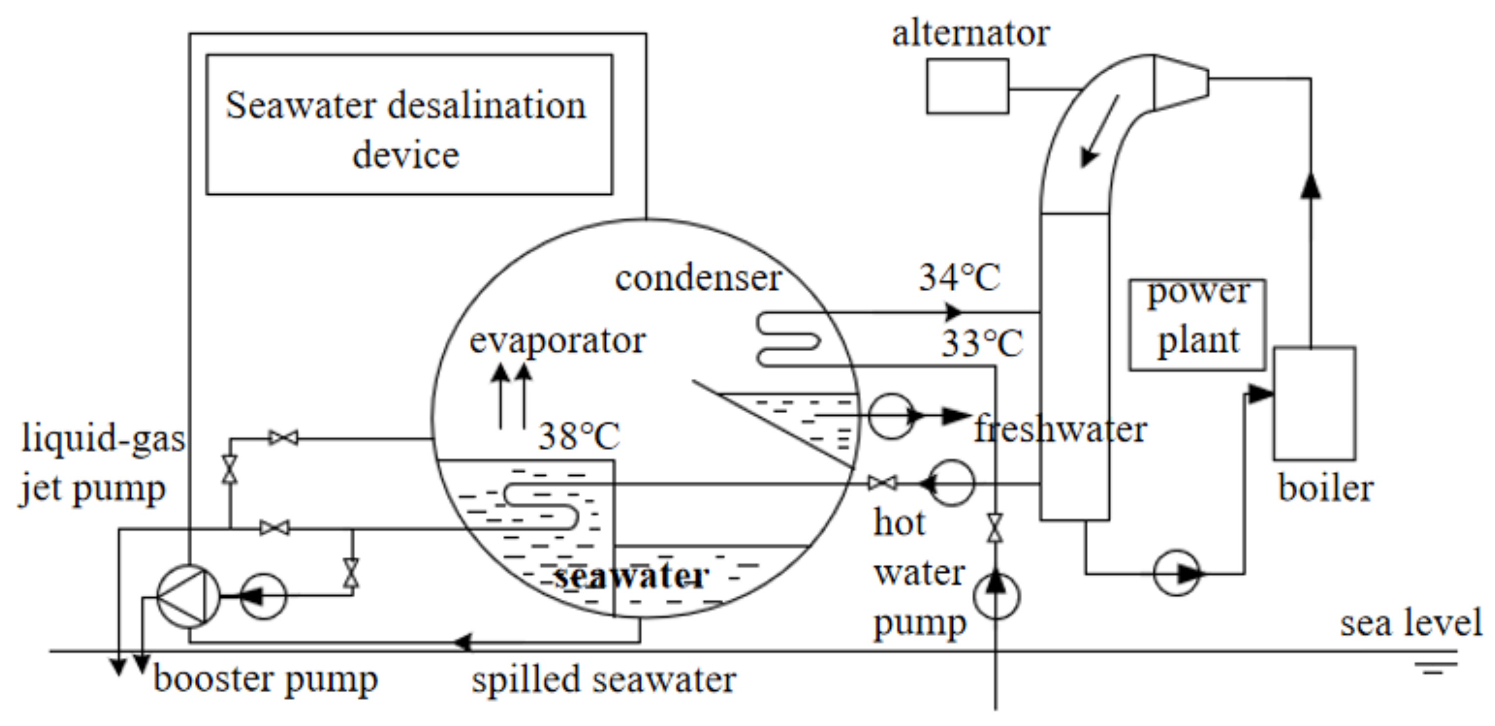
In seawater desalination systems, heated seawater is used as the working liquid of the LGJP (see Figure 3). The LGJP is used to vacuum the evaporation chamber and reduce the pressure of the evaporation chamber to reduce the boiling point of seawater and accelerate evaporation to desalinate the seawater [94,95].
In recent years, most of the research on the LGJP has been carried out around its application in the field of oil and gas. The Wellcom system invented by Caltech can effectively solve the problem of high gas volume fraction that often occurs in deep-sea oil exploration [96]. Since the mixture from the high-pressure well needs gas–liquid separation, this can be achieved by installing a rotary liquid–gas separator at the inlet of the jet pump. The gas is discharged through the pipeline, and the separated liquid is used as the motive fluid, which flows through the jet pump. Entering the LGJP, the gas separated by the rotary separator is sucked by the LGJP at the same time, and the two mixed fluids are mixed by the LGJP to form a liquid–gas mixture with a lower density (see Figure 4). This overcomes gravity and resistance, and at the same time, the system removes the accumulated liquid in the pipeline and reduces the pressure loss along the pipeline, which can further reduce the pressure of the flowing tubing head of the low-pressure well and improve production efficiency.

4.2. Application Research Status of the CJVP

The CJVP has no impeller structure, so cavitation will not occur during use. It can be used to pump toxic, corrosive and impurity-containing gases and can be used in petrochemical production. Deaeration of industrial boiler feed water can improve the corrosion of the boiler body and steam pipe equipment. At the same time, the content of noncondensable gas in steam is low because the feed water is deaerated, and the utilization rate of the steam enthalpy can be increased by 50 times, which greatly saves gas consumption. Using the CJVP for deaeration not only saves energy but also consumes less water, has a small volume and occupies little space. In the alkali recovery process in the paper industry, it is necessary to pump out the noncondensable gas in the condenser using a vacuum pump. The CJVP with low power consumption and a compact structure is adopted, and the maximum vacuum degree can reach more than 95% for the purpose of vacuum evaporation [9].
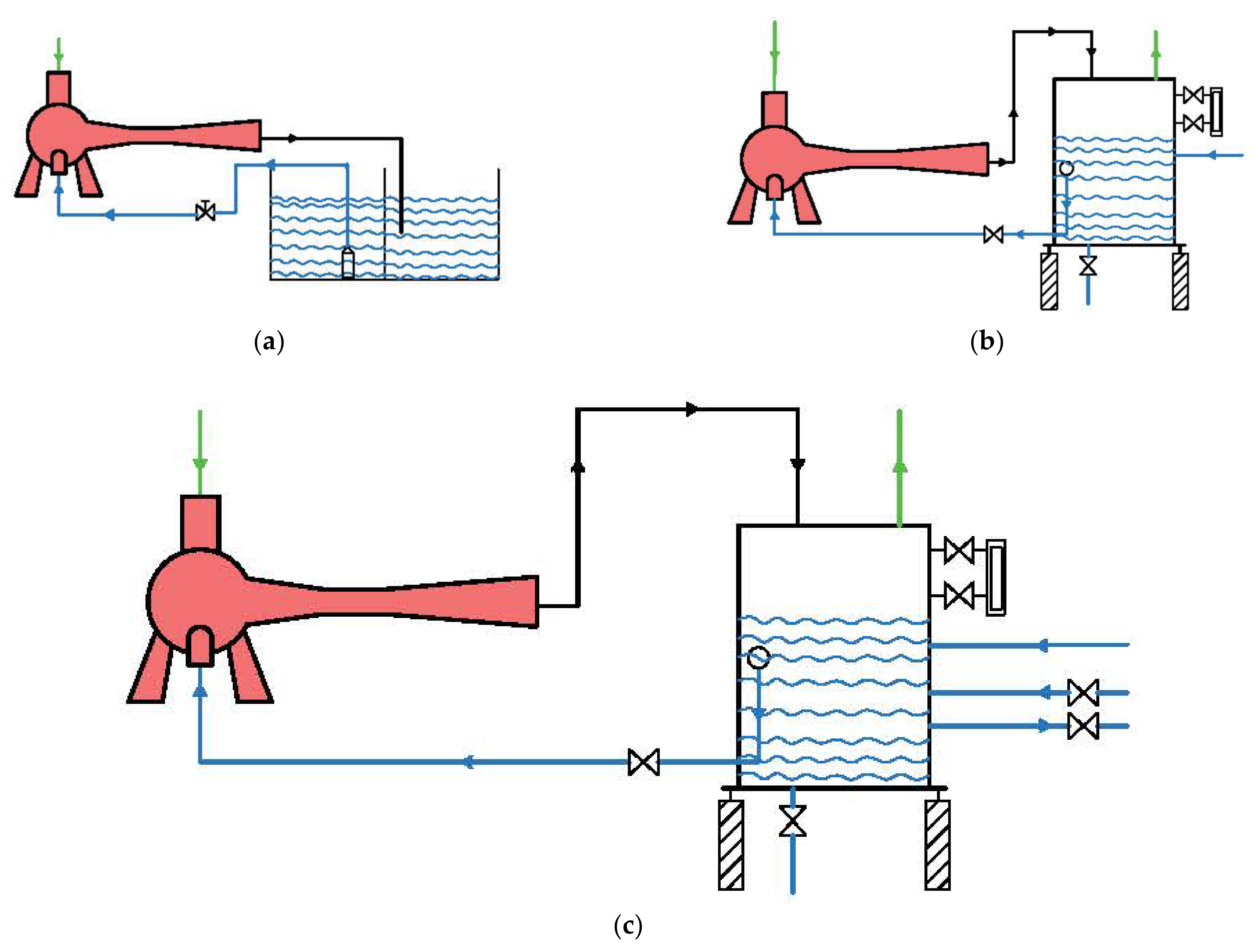
The impeller of the water ring vacuum pump is prone to cavitation during operation, and it is also prone to large selection and power consumption. Choosing the CJVP to replace the traditional water ring vacuum pump in a thermal power plant can effectively avoid these problems. At the same time, the application of the CJVP in the vacuum pumping system of a thermal power plant does not require major changes to the original vacuum pumping system; the CJVP can replace the original water ring vacuum pump, and the structure of other parts can remain unchanged. In the application of the CJVP, its runner structure will not produce cavitation and will maintain a stable operation, which can truly achieve high efficiency and low consumption. At the same time, the application of the CJVP in a thermal power plant can have three installation modes: open primary circulation, secondary circulation and closed circulation (see Figure 5). The open circulation uses the circulating water supply of the power plant as the working water for the CJVP, and the pumped steam–water mixture is directly discharged into the trench. The outlet pressure of the circulating water in this installation mode is low, so that the steam in the steam–water mixture can be released. At the same time, the system is simple, the operation is convenient, and the installation area is small. However, since the working water is not recovered, its water consumption is large, which is suitable for areas with abundant water resources. The secondary circulation installation is to install a pool at the inlet of the CJVP so that the pump can achieve a self-absorption cycle. When starting the pump, it needs to use water pressure to establish a siphon and then reuses the water in the pool for recycling. Its advantage is that it can save water in areas with tight water resources. Closed circulation is equipped with a steam water separator for the air extraction system of the CJVP. The CJVP and the steam water separator are assembled together so that the outlet steam–water mixture of the CJVP is discharged to the top of the steam water separator. The bottom of the steam water separator is connected to the inlet of the CJVP. The air separated in the steam water separator is directly discharged, and the cooling water of the steam water separator comes from the circulating water of the power plant. The system has the advantages of large air extraction, low noise and vibration, a small floor area, and fast installation. A thermal power plant can select the appropriate installation mode according to its own conditions [91].

5. Conclusions

As a type of conveying equipment integrating mixing, reaction and absorption, the LGJP has superiority and irreplaceability in many technological processes. This paper summarizes the development process of the LGJP based on theoretical derivations, experimental tests, simulations and practical applications and focuses on the PLGJP, especially the centrifugal jet vacuum pump. From the analysis of the existing research status, the development direction of the LGJP is as follows:
(1)
CFD will be more deeply applied to the mechanism research and performance improvement of the LGJP. The theoretical research of the LGJP has been in-depth, and combined with CFD technology, the mechanism analysis of the LGJP is also progressing. At present, the research of the LGJP tends to combine simulation analysis with practical application fields to analyze the flow and suction mechanism to carry out targeted structural optimization, reduce research and development and application costs, and improve reliability.
(2)
The diversity and multiphase of the fluid medium and its influence on the internal flow mechanism are the research directions of the LGJP. The application of the LGJP is no longer limited to liquid–gas two-phase flow, and it is not uncommon for the working fluid or the aspirated fluid to be a liquid–gas mixture or non-Newtonian fluid. At present, there are few studies on the internal flow mechanism of the LGJP in the case of multiphase mixed flow medium, which needs further attention.
(3)
The PLGJP provides more energy-saving options. Today, when energy saving and consumption reduction are required, the PLGJP provides a new idea for energy-saving transformation in various industries, and the research on related mechanisms can expand the application scope of the LGJP in the future. However, there are few studies on the relevant mechanism of the PLGJP, and these are needed to improve the theoretical and experimental research.
(4)
The application prospect of the CJVP is broad. The characteristics of the high efficiency and low consumption of the CJVP results in its broad application in the market today, as it advocates energy conservation and emission reduction. It is precisely because of the high market demand that the related theoretical and experimental research on CJVPs is very urgent and needs more attention.

Author Contributions

Conceptualization, X.Y. and J.M.; methodology, D.Z.; validation, Q.Z., M.X. and H.Z.; formal analysis, H.Z.; writing—original draft preparation, H.Z.; writing—review and editing, X.Y.; supervision, J. M. All authors have read and agreed to the published version of the manuscript.

Funding

This research was funded by the Zhejiang Provincial Science and Technology Plan Project of China (Grant No. 2021C01052) and the National Natural Science Foundation of China (Grant No. 51909235).

Data Availability Statement

Not applicable.

Conflicts of Interest

The authors declare no conflict of interest.

References

  1. Witte, J.H. Mixing Shocks and Their Influence on the Design of Liquid-Gas Ejectors. Master’s Thesis, Delft University, Delft, The Netherlands, 1962. [Google Scholar]
  2. Cunningham, R.G. Liquid jet pumps for two-phase flows. J. Fluids Eng. 1995, 117, 309–316. [Google Scholar] [CrossRef]
  3. Sherif, S.; Lear, W.; Steadham, J.; Hunt, P.; Holladay, J. Analysis and modeling of a two-phase jet pump of a thermal management system for aerospace applications. Int. J. Mech. Sci. 2000, 42, 185–198. [Google Scholar] [CrossRef]
  4. Kumar, R.S.; Mani, A.; Kumaraswamy, S. Analysis of a jet-pump-assisted vacuum desalination system using power plant waste heat. Desalination 2005, 179, 345–354. [Google Scholar] [CrossRef]
  5. Neve, R.S. The performance and modeling of liquid jet gas pumps. Int. J. Heat Fluid Flow 1988, 9, 156–164. [Google Scholar] [CrossRef]
  6. Carvalho, P.M. Modeling the Electrical Submersible Jet Pump Producing High Gas-Liquid-Ratio Petroleum Wells. Ph.D. Thesis, The University of Texas at Austin, Austin, TX, USA, 1998. [Google Scholar]
  7. Neve, R.S. Diffuser performance in two-phase jet pumps. Int. J. Multiph. Flow 1991, 17, 267–272. [Google Scholar] [CrossRef]
  8. Lu, H. Theory and Application of Jet Pump Technology; Water Conservancy and Electric Power Press: Beijing, China, 1989. [Google Scholar]
  9. Lu, H. Theory and Application of Jet Technology; Wuhan University Press: Wuhan, China, 2004. [Google Scholar]
  10. Liao, D.; Lu, H. Research on basic performance and correction coefficients of liquid-liquid gas jet pump. Chin. J. Hydrodyn. 1996, 12, 610–617. [Google Scholar]
  11. Haidl, J.; Mařík, K.; Moucha, T.; Rejl, F.J.; Valenz, L.; Zednikova, M. Hydraulic characteristics of liquid–gas ejector pump with a coherent liquid jet. Chem. Eng. Res. Des. 2021, 168, 435–442. [Google Scholar] [CrossRef]
  12. Rahman, F.; Umesh, D.; Subbarao, D.; Ramasamy, M. Enhancement of entrainment rates in liquid–gas ejectors. Chem. Eng. Process. Process Intensif. 2010, 49, 1128–1135. [Google Scholar] [CrossRef]
  13. Opletal, M.; Novotný, P.; Linek, V.; Moucha, T.; Kordač, M. Gas suction and mass transfer in gas-liquid up-flow ejector loop reactors. Effect of nozzle and ejector geometry. Chem. Eng. J. 2018, 353, 436–452. [Google Scholar] [CrossRef]
  14. Kim, M.I.; Kim, O.S.; Lee, D.H.; Kim, S.D. Numerical and experimental investigations of gas–liquid dispersion in an ejector. Chem. Eng. Sci. 2007, 62, 7133–7139. [Google Scholar] [CrossRef]
  15. Sharma, V.P.; Kumaraswamy, S.; Mani, A. Effect of various nozzle profiles on performance of a two-phase flow jet pump. Int. J. Mech. Aerosp. Ind. Mechatron. Manuf. Eng. 2012, 1, 173–179. [Google Scholar] [CrossRef]
  16. Liu, J. Experimental Research on performance of liquid-air jet pump. J. Wuhan Inst. Water Conserv. Electr. Power 1982, 3, 105–114. [Google Scholar]
  17. Liao, D.; Lu, H. Study on basic performance and correction coefficients of liquid-liquid gas jet pump. Fluid Mach. 1997, 4, 26–29. [Google Scholar]
  18. Gao, C.; Wang, Y. Research and application progress of liquid-gas jet pump. China Pet. Mach. 2008, 2, 67–70. [Google Scholar]
  19. Zhang, J.; Gao, C.; Yan, Y.; Wang, X. Pulsed liquid-air jet pump energy balance. J. Drain. Irrig. Mach. 2012, 30, 422–427. [Google Scholar] [CrossRef]
  20. Ge, Y.; Ge, Q.; Yang, J. Numerical simulation of throat distance of liquid-gas jet pump and its optimal range determination. Fluid Mach. 2012, 40, 21–24. [Google Scholar] [CrossRef]
  21. Bhatkar, V.; Sur, A. An experimental analysis of liquid air jet pump. Front. Heat Mass Transf. (FHMT) 2021, 17, 12. [Google Scholar] [CrossRef]
  22. Wu, Y.L.; Xiang, Q.J.; Li, H.; Chen, S.X. Study on bubble sizes in a down-flow liquid jet gas pump. IOP Conf. Ser. Earth Environ. Sci. 2012, 15, 052017. [Google Scholar] [CrossRef]
  23. Eisallak, M.; Hefny, M.M. Experimental investigation of the performance of liquid gas jet pumps with inlet swirling. Proc. Inst. Mech. Eng. Part A J. Power Energy 2010, 224, 363–372. [Google Scholar] [CrossRef]
  24. Mikheev, N.I.; Davletshin, I.A.; Mikheev, A.N.; Kratirov, D.V.; Fafurin, V.A. Efficiency of liquid-jet high-pressure booster compressors. J. Phys. Conf. Ser. 2017, 891, 012202. [Google Scholar] [CrossRef]
  25. Zhang, Y.; Zhao, J.; Liu, Z.; Zuo, P.; Kwabena, A.R. Numerical simulation and parameter study of ejector in casing gas recovery system. J. Mech. Sci. Technol. 2021, 35, 2689–2696. [Google Scholar] [CrossRef]
  26. Choi, S.H.; Ji, H.S.; Kim, K.C. Comparative study of hydrodynamic characteristics with respect to direction of installation of gas-liquid ejector system. J. Mech. Sci. Technol. 2015, 29, 3267–3276. [Google Scholar] [CrossRef]
  27. Jiao, B.; Blais, R.N.; Schmidt, Z. Efficiency and pressure recovery in hydraulic jet pumping of two-phase gas/liquid mixtures. SPE Prod. Eng. 1990, 5, 361–364. [Google Scholar] [CrossRef]
  28. Ismagilov, A.R.; Spiridonov, E.K. Operational process and characteristics of liquid-gas jet pumps with the ejected vapor-gas medium. Procedia Eng. 2016, 150, 247–253. [Google Scholar] [CrossRef] [Green Version]
  29. Sharma, D.; Patwardhan, A.; Ranade, V. Effect of turbulent dispersion on hydrodynamic characteristics in a liquid jet ejector. Energy 2018, 164, 10–20. [Google Scholar] [CrossRef]
  30. Chen, L.; Liu, S. Numerical simulation of internal flow field of pulsed liquid-gas jet pump. Machinery 2013, 8, 29–31. [Google Scholar] [CrossRef]
  31. Semlitsch, B. Large Eddy Simulation of Turbulent Compressible Jets. Ph.D. Thesis, KTH Royal Institute of Technology, Stockholm, Sweden, 2014. [Google Scholar]
  32. Zheng, P.; Qin, J.; Chen, X. Numerical simulation and optimization of gas-liquid ejector ejection performance. J. Jiangsu Univ. (Nat. Sci. Ed.) 2017, 38, 30–36. [Google Scholar] [CrossRef]
  33. Qin, J.; Zheng, P.; Chen, X. Numerical simulation of gas-liquid ejector jet performance under different inlet and outlet conditions. Chin. J. Process Eng. 2017, 17, 469–476. [Google Scholar] [CrossRef]
  34. Gao, G.; Xing, Y.; Wang, Y. Numerical study on the influence of the constriction half angle of the throat segment on the flow field characteristics of a liquid-air jet pump. Chin. J. Vac. Sci. Technol. 2020, 40, 174–179. [Google Scholar]
  35. Wang, X.; Li, H.; Dong, J.; Wu, J.; Tu, J. Numerical study on mixing flow behavior in gas-liquid ejector. Exp. Comput. Multiph. Flow 2021, 3, 108–112. [Google Scholar] [CrossRef]
  36. Yang, X.; Long, X.; Kang, Y.; Xiao, L. Application of constant rate of velocity or pressure change method to improve annular jet pump performance. Int. J. Fluid Mach. Syst. 2013, 6, 137–143. [Google Scholar] [CrossRef]
  37. Wang, X.; Yang, X.; Long, X.; Zhou, D. Application of constant rate of velocity change method to improve dust cleaning performance. Disaster Adv. 2013, 6, 459–468. [Google Scholar]
  38. Xiao, J.; Wu, Q.; Chen, L.; Ke, W.; Wu, C.; Yang, X.; Yu, L.; Jiang, H. Assessment of different CFD modeling and solving approaches for a supersonic steam ejector simulation. Atmosphere 2022, 13, 144. [Google Scholar] [CrossRef]
  39. Yang, X.; Long, X.; Kang, Y.; Xiao, L. Effect of diffuser structure and throat length on jet pump performance. J. Harbin Inst. Technol. 2014, 46, 111–115. [Google Scholar] [CrossRef]
  40. Sato, K.; Hachino, K.; Saito, Y. Inception and dynamics of traveling-bubble-type cavitation in a venturi. In Proceedings of the ASME/JSME 2003 4th Joint Fluids Summer Engineering Conference, Honolulu, HI, USA, 6–10 July 2003; Volume 36967, pp. 279–285. [Google Scholar]
  41. Stutz, B.; Legoupil, S. X-ray measurements within unsteady cavitation. Exp. Fluids 2003, 35, 130–138. [Google Scholar] [CrossRef]
  42. Coutier Delgosha, O.; Reboud, J.; Delannoy, Y. Numerical simulation of the unsteady behaviour of cavitating flows. Int. J. Numer. Methods Fluids 2003, 42, 527–548. [Google Scholar] [CrossRef]
  43. Coutier Delgosha, O.; Fortes Patella, R.; Reboud, J.L. Evaluation of the turbulence model influence on the numerical simulations of unsteady cavitation. J. Fluids Eng. 2003, 125, 38–45. [Google Scholar] [CrossRef]
  44. Gu, Y.; Ma, L.; Yan, M.; He, C.; Zhang, J.; Mou, J.; Wu, D.; Ren, Y. Strategies for improving friction behavior based on carbon nanotube additive materials: A review. Tribol. Int. 2022, 228, 107490. [Google Scholar] [CrossRef]
  45. He, C.; Gu, Y.; Zhang, J.; Ma, L.; Yan, M.; Mou, J.; Ren, Y. Preparation and modification technology analysis of Ionic Polymer-Metal Composites (IPMCs). Int. J. Mol. Sci. 2022, 23, 3522. [Google Scholar] [CrossRef]
  46. Gu, Y.; Zhang, J.; Yu, S.; Mou, C.; Li, Z.; He, C.; Wu, D.; Mou, J.; Ren, Y. Unsteady numerical simulation method of hydrofoil surface cavitation. Int. J. Mech. Sci. 2022, 228, 107490. [Google Scholar] [CrossRef]
  47. Yazici, B.; Tuncer, I.; Ak, M. Numerical & experimental investigation of flow through a cavitating venturi. In Proceedings of the 2007 3rd International Conference on Recent Advances in Space Technologies, Istanbul, Turkey, 14–16 June 2007; pp. 236–241. [Google Scholar]
  48. Sayyaadi, H. Instability of the cavitating flow in a venturi reactor. Fluid Dyn. Res. 2010, 42, 055503. [Google Scholar] [CrossRef]
  49. Xu, C.; Huang, Y. Experimental characteristics of pneumatic pulse jet pumping systems with a Venturi-like reverse flow diverter. Int. J. Chem. React. Eng. 2011, 9, A34. [Google Scholar] [CrossRef]
  50. Long, X.; Wang, J.; Zuo, D.; Zhang, J.; Ji, B. Experimental Investigation of the instability of cavitation in veturi tube under different cavitation Stage. J. Mech. Eng. 2018, 54, 209–215. [Google Scholar] [CrossRef]
  51. Wang, J.; Xu, S.; Cheng, H.; Ji, B.; Zhang, J.; Long, X. Experimental investigation of cavity length pulsation characteristics of jet pumps during limited operation stage. Energy 2018, 163, 61–73. [Google Scholar] [CrossRef]
  52. Yan, H.; Wang, Z.; Chen, Y. High-speed photography analysis on cavitation of Venturi injector. J. Drain. Irrig. Mach. Eng. 2014, 32, 901–905. [Google Scholar] [CrossRef]
  53. Hu, B.; Musculus, M.P.B.; Oefelein, J.C. The influence of large-scale structures on entrainment in a decelerating transient turbulent jet revealed by large eddy simulation. Phys. Fluids 2012, 24, 045106. [Google Scholar] [CrossRef]
  54. Xu, M.; Yang, X.; Long, X.; Lyu, Q. Large eddy simulation of turbulent flow structure and characteristics in an annular jet pump. J. Hydrodyn. 2017, 29, 702–715. [Google Scholar] [CrossRef]
  55. Xu, M.; Yang, X.; Long, X.; Lyu, Q.; Ji, B. Numerical investigation of turbulent flow coherent structures in annular jet pumps using the LES method. Sci. China Technol. Sci. 2018, 61, 86–97. [Google Scholar] [CrossRef]
  56. Yang, X.; Long, X. Numerical investigation on the jet pump performance based on different turbulence models. IOP Conf. Ser. Earth Environ. Sci. 2012, 15, 052019. [Google Scholar] [CrossRef]
  57. Yang, X.; Long, X.; Yao, X. Numerical investigation on the mixing process in a steam ejector with different nozzle structures. Int. J. Therm. Sci. 2012, 56, 95–106. [Google Scholar] [CrossRef]
  58. Kolář, J. Error analysis of supersonic air-to-air ejector schlieren pictures. EPJ Web Conf. 2013, 45, 01004. [Google Scholar] [CrossRef]
  59. Gagan, J.; Smierciew, K.; Butrymowicz, D.; Karwacki, J. Comparative study of turbulence models in application to gas ejectors. Int. J. Therm. Sci. 2014, 78, 9–15. [Google Scholar] [CrossRef]
  60. El-Behery, S.M.; Hamed, M.H. A comparative study of turbulence models performance for separating flow in a planar asymmetric diffuser. Comput. Fluids 2011, 44, 248–257. [Google Scholar] [CrossRef]
  61. Kolář, J.; Dvořák, V. Verification of K-ω SST turbulence model for supersonic internal flows. Int. J. Mech. Mechatron. Eng. 2011, 5, 1715–1719. [Google Scholar] [CrossRef]
  62. Semlitsch, B.; Laurendeau, E.; Mihăescu, M. Steady-State and unsteady simulations of a high velocity jet into a venturi shaped pipe. In Proceedings of the Fluids Engineering Division Summer Meeting, Chicago, IL, USA, 3–7 August 2014; American Society of Mechanical Engineers: New York, NY, USA, 2014; Volume 46230, p. V01CT16A023. [Google Scholar] [CrossRef]
  63. Liang, Y.Z.; Long, Y.; Long, X.; Cheng, H. Verification and validation of large eddy simulation of cavitating flow in Venturi. Chin. J. Ship Res. 2022, 17, 196–204. [Google Scholar] [CrossRef]
  64. Zhao, J.; Liu, C.; Dong, Y.; He, Q.; Wan, F.; Friedrich, T.; Bi, X.; Tian, Y. Flue gas fine treatment by ejecting technology. Proc. Inst. Mech. Eng. Part C J. Mech. Eng. Sci. 2019, 233, 4311–4318. [Google Scholar] [CrossRef]
  65. Zhao, J.; Wei, X.; Zou, J.; Zhang, Y.; Sun, J.; Liu, Z. Research on performance optimization of gas–liquid ejector in multiphase mixed transportation device. J. Mech. 2022, 38, 22–31. [Google Scholar] [CrossRef]
  66. Sliusenko, A.; Ponomarenko, V.; Forostiuk, I. Water-air ejector with conical-cylindrical mixing chamber. Acta Polytech. 2021, 61, 768–776. [Google Scholar] [CrossRef]
  67. Kumar, R.S.; Kumaraswamy, S.; Mani, A. Experimental investigations on a two-phase jet pump used in desalination systems. Desalination 2007, 204, 437–447. [Google Scholar] [CrossRef]
  68. Drozdov, A.N.; Malyavko, E.A.; Alekseev, Y.L.; Shashel, O.V. Stand research and analysis of liquid-gas jet-pump’s operation characteristics for oil and gas production. In Proceedings of the SPE Annual Technical Conference and Exhibition, Denver, CO, USA, 30 October–2 November 2011. [Google Scholar] [CrossRef]
  69. Asuaje, M.; Toteff, J.; Noguera, R. Evaluation of a jet-pump for the improvement of oil-water flow in pipeline loops using CFD tools. E3S Web Conf. 2021, 321, 02012. [Google Scholar] [CrossRef]
  70. Asfora, L.; dos Santos, A.; Duarte, L.J.N. Modeling multiphase jet pumps for gas compression. J. Pet. Sci. Eng. 2019, 173, 844–852. [Google Scholar] [CrossRef]
  71. Kolla, S.S.; Mohan, R.S.; Shoham, O. Numerical analysis of flow behavior in Gas–Liquid Cylindrical Cyclone (GLCC©) separators with inlet design modifications. J. Energy Resour. Technol. 2021, 143, 093005. [Google Scholar] [CrossRef]
  72. Bazaluk, O.; Dubei, O.; Ropyak, L.; Shovkoplias, M.; Pryhorovska, T.; Lozynskyi, V. Strategy of compatible use of jet and plunger pump with chrome parts in oil well. Energies 2021, 15, 83. [Google Scholar] [CrossRef]
  73. Toteff, J.; Asuaje, M.; Noguera, R. New design and optimization of a jet pump to boost heavy oil production. Computation 2022, 10, 11. [Google Scholar] [CrossRef]
  74. Tang, J.; Zhou, Y.; Liu, J.; Wang, J.; Zhu, W. Liquid metal actuated ejector vacuum system. Appl. Phys. Lett. 2015, 106, 031901. [Google Scholar] [CrossRef]
  75. Tang, J.; Zhang, Z.; Li, L.; Wang, J.; Liu, J.; Zhou, Y. Influence of driving fluid properties on the performance of liquid-driving ejector. Int. J. Heat Mass Transf. 2016, 101, 20–26. [Google Scholar] [CrossRef]
  76. Wang, L.; Gao, C. Study progress of pulse jet pump. Integr. Intell. Energy 2006, 28, 33–35. [Google Scholar] [CrossRef]
  77. Long, X.; Lu, H. Derivation of performance equation of unsteady jet pump. Fluid Mach. 1997, 25, 26–29. [Google Scholar]
  78. Lu, H.; Gao, C.; Long, X.; Wang, S.; Cheng, M. Research on design theory of gas liquid piston pulsed liquid jet pump. Fluid Mach. 1996, 10, 3–6. [Google Scholar]
  79. Lu, H.; Gao, C. Theoretical study on the efficiency of gas-liquid piston pulsed liquid jet pump. Mech. Electr. Eng. Technol. 2000, 4, 33–36. [Google Scholar] [CrossRef]
  80. Gao, C.; Lu, H.J. Theoretical study on the performance of gas-liquid piston pulsed liquid jet pump. Mech. Electr. Eng. Technol. 2000, 4, 52–56. [Google Scholar] [CrossRef]
  81. Gao, C.; Lu, H.; Liao, D. Theoretical study on stability of gas liquid piston pulsed liquid jet pump. Chin. J. Appl. Mech. 2001, 18, 129–134. [Google Scholar] [CrossRef]
  82. Gao, C.; Wang, Y.; Chen, H.; Lei, T.; Chen, X.; Wang, X. Basic performance test of pulsed liquid-air jet pump. Nucl. Power Eng. 2010, 31, 133–137. [Google Scholar]
  83. Guo, Y.; Jing, S.; Zhang, J.; Wu, Q.; Song, C. Experimental study on performance of pneumatic pulsed liquid jet pump. Nucl. Sci. Eng. 2004, 24, 65–71. [Google Scholar] [CrossRef]
  84. Wang, L.H.; Gan, C.; Ning, P.H. Numerical Study on throat tube inlet function of Pulsed Liquid Jet Pump. Adv. Mater. Res. 2012, 354, 650–654. [Google Scholar] [CrossRef]
  85. Nygård, A.; Altimira, M.; Semlitsch, B.; Wittberg, L.; Fuchs, L. Analysis of vortical structures in intermittent jets. In Proceedings of the 5th International Conference on Jets, Wakes and Separated Flows (ICJWSF2015), Stockholm, Sweden, 15–18 June 2015; Springer: Cham, Switzerland, 2016; pp. 3–10. [Google Scholar] [CrossRef]
  86. Lu, H.; Gui, Z.; Sun, M. Mechanism analysis and experimental research of centrifugal jet vacuum pump. Fluid Mach. 1988, 9, 18–25. [Google Scholar]
  87. Wu, Y.; Ge, L.; Chen, N. Large eddy simulation of silt-liquid two-phase flow through a centrifugal pump impeller. J. Tsinghua Univ. (Sci. Technol.) 2001, 41, 93–96. [Google Scholar] [CrossRef]
  88. Guo, R.; Li, R.; Zhang, R.; Song, Q. Characteristic analysis of interior hydrodynamic noise in jetting centrifugal pump. Trans. Chin. Soc. Agric. Mach. 2018, 49, 156–164. [Google Scholar] [CrossRef]
  89. Sun, M. Analysis of power consumption of liebrand vacuum pump. Electr. Power 1981, 6, 30–33. [Google Scholar]
  90. Shen, X. Comparison and analysis of technical performance of ZBK21 water jet vacuum pump, SZ water ring vacuum pump and hydraulic ejector. China Pap. 1984, 3, 38–41. [Google Scholar]
  91. Electric Power Science and Technology Network. Available online: http://www.eptchina.com/video/record202012243857.html (accessed on 16 June 2022).
  92. Luo, H.; Zhou, P.; Shu, L.; Mou, J.; Zheng, H.; Jiang, C.; Wang, Y. Energy performance curves prediction of centrifugal pumps based on constrained PSO-SVR model. Energies 2022, 15, 3309. [Google Scholar] [CrossRef]
  93. Chen, X.; Zhang, R.; Jiang, L.; Guo, G. DMD analysis on the unsteady flow in a centrifugal pump impeller. J. Vib. Shock. 2022, 41, 33–40+57. [Google Scholar]
  94. Wu, B. Performance Research and Numerical Simulation of Liquid-Gas Jet Pump. Master’s Thesis, Southwest Petroleum University, Chengdu, China, 2017. [Google Scholar]
  95. Yuan, G.; Zhang, L.; Zhang, H.; Wang, Z. Numerical and experimental investigation of performance of the liquid–gas and liquid jet pumps in desalination systems. Desalination 2011, 276, 89–95. [Google Scholar] [CrossRef]
  96. Sarshar, S. The recent applications of jet pump technology to enhance production from tight oil and gas fields. In Proceedings of the SPE Middle East Unconventional Gas Conference and Exhibition, Abu Dhabi, United Arab Emirates, 23–25 March 2012. [Google Scholar]
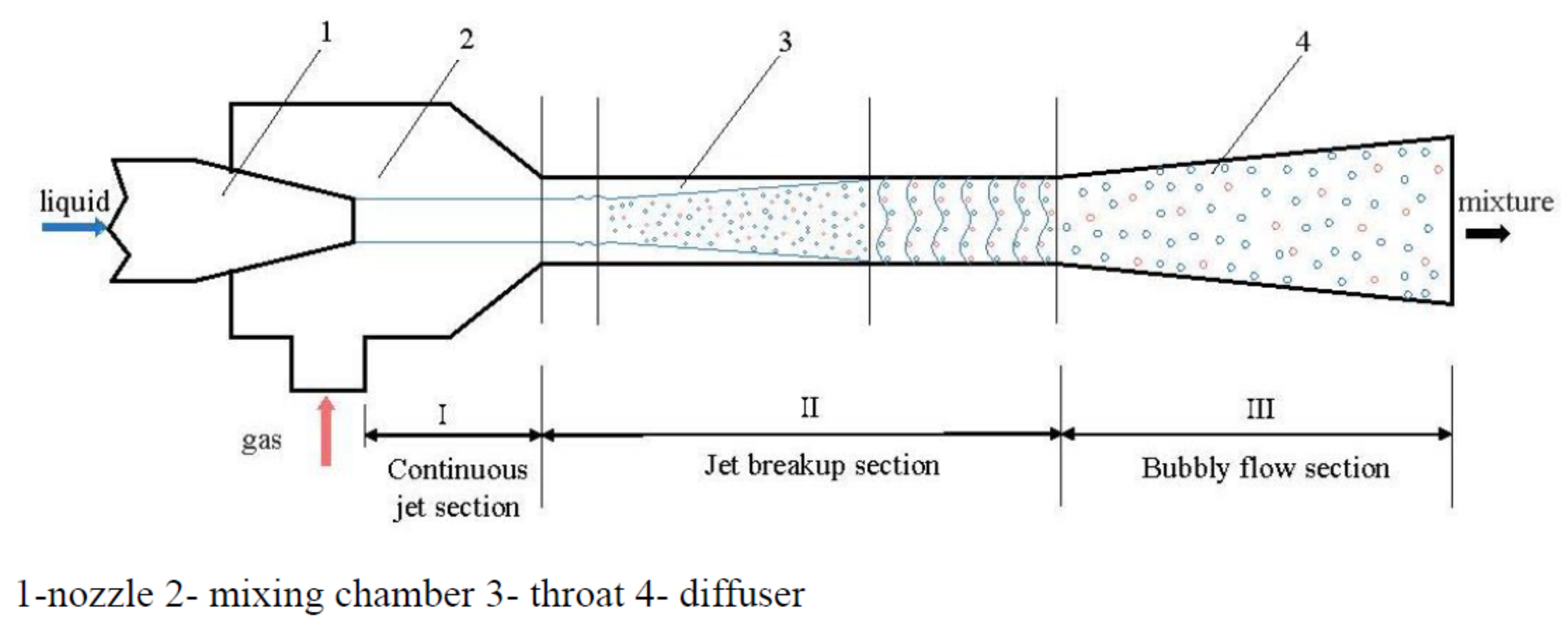
Figure 1. Working principle and structure diagram of the LGJP.
Energies 15 06978 g001
Figure 2. Working principle and structure diagram of the CJVP.
Energies 15 06978 g002
Figure 3. Seawater desalination system.
Energies 15 06978 g003
Figure 4. Schematic diagram of Wellcom system.
Energies 15 06978 g004
Figure 5. Application of the CJVP in thermal power plant. (a) Open primary circulation, (b) secondary circulation, (c) closed circulation.
Energies 15 06978 g005
Publisher’s Note: MDPI stays neutral with regard to jurisdictional claims in published maps and institutional affiliations.