Abstract
The multicomponent alloys with nearly equal concentration of components, also known as high entropy alloys (HEAs), were first proposed 22 years ago. The HEAs quickly became very important in materials science due to their unique properties. Nowadays, the HEAs are frequently used in energy conversion and storage applications. HEAs can consist of five, six or more components. Plasma cladding permits coating of the large surfaces of cheap substrates with (often expensive) HEAs and to enlarge, in such a way, their application area. The large-area coatings deposited by plasma cladding possess multiple advantages such as low thermal distortion, very high energy density, as well as low dilution of the substrate material. Plasma cladding ensures good metallurgical bonding between coating and substrate. The costs of operation and equipment are also very attractive. During plasma cladding, the mixed powders are blown by carrier gas into a plasma torch or are positioned on a substrate. This powder mixture is then melted in or under the plasma torch. The plasma torch, in turn, sequentially scans the substrate. After finalizing the crystallization process, the solid polycrystal appears which contains few residual melts. This remaining melt can completely or incompletely wet the grain boundaries (GBs) in solid phase of the polycrystal. These completely or incompletely wetted GBs can strongly influence the microstructure of HEA coatings and their morphology. In this review we analyze the GB wetting HEAs containing one phase in HEAs with two, three and more phases, as well as in HEAs reinforced with particles of carbides, nitrides, borides, or oxides. We also analyze the microstructure of the rather thick coatings after plasma cladding after additional laser remelting and observe how GB wetting changes over their thickness.
1. Introduction
In recent years, high entropy alloys (HEAs) have become a research hotspot in materials science. Nowadays, HEAs are frequently used for the energy conversion and storage applications [1,2,3,4]. HEAs are also called multi-principal alloys, baseless alloys, or alloys without main component. They were first proposed by Brian Cantor and coworkers [5] and Jien-Wei Yeh and his team [6]. The first HEAs were alloys with six or more components in equiatomic proportions. It was unexpected that such alloys may form a uniform disordered solid solution. This is because their unique combination of atoms with different atomic radii can strongly prevent the nucleation of second phases and their subsequent growth [5,6,7,8,9,10,11,12]. Such alloys can exhibit better properties than traditional alloys. In particular, they possess high hardness [7,8], good strength at high temperatures [9], and excellent wear, oxidation, and corrosion resistance [10,11,12]. The most used approaches to manufacturing HEAs are casting or arc melting technologies [5,6,7,8,9,10,11,12]. In these methods, the elemental powders are mixed first and then remelted several times in order to ensure the homogeneity of HEAs. However, the size of HEA parts produced by casting or arc melting is limited. This fact impedes the application of HEAs. One of the ways to overcome this restriction is to produce the part from other regular or ordinary (possibly even cheaper) material and to deposit the HEA coating on the surface. Due to this fact, various methods were used to produce the HEA coatings, such as plasma cladding [1,2,13,14], plasma spray [15,16,17,18,19,20,21,22], thermal spray [23], laser cladding [24,25,26,27], magnetron sputtering [28,29,30,31,32,33,34,35,36,37], vacuum arc deposition [38,39,40,41], electric arc deposition [42], and electron beam deposition [43]. All these deposition methods have their advantages and disadvantages. For example, thermal spraying can take place in low vacuum. On the other hand, the increased oxidation of the components can proceed. The magnetron sputtering or vacuum arc deposition ensure high density and uniformity of coatings, they also do not include melting of HEA during manufacturing. However, the maximal thickness does not exceed a few μm. In the case of plasma cladding, the coatings can be a hundred times thicker. Also, the small droplets of a melt can form during the vacuum arc deposition; in most cases, they need to be filtered with magnetic loops, decreasing the deposition rate. The magnetron sputter-deposited films have columnar grain structure, and the coatings after vacuum arc deposition have uniform equiaxed grains. We listed here only several differences of HEA synthesis methods. Each of them has, therefore, its own niche (which frequently partly overlaps with those of other synthesis methods). This review discusses the plasma cladding, which started to be developed quite recently, just few years ago, and, nevertheless, has already taken its own place among other technologies.
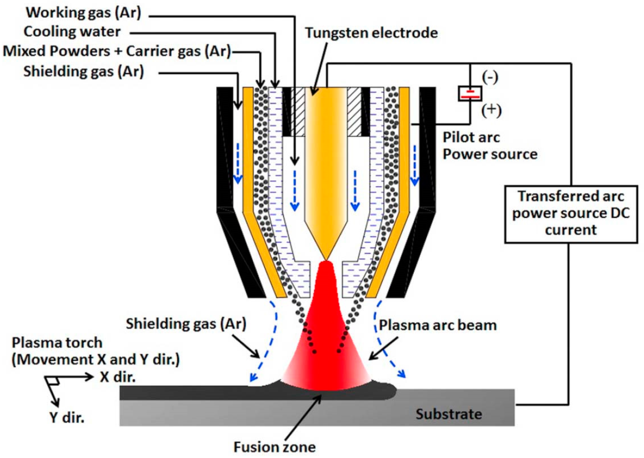
Plasma cladding is an effective way to manufacture the coatings with large area, with advantages such as low thermal distortion, very high energy density, as well as small dilution of the substrate material [40,41]. Plasma cladding assures good metallurgical bonding between coating and substrate, it also has a low cost in equipment and operation [42,43]. The powder of a material to be clad melts rapidly under the plasma torch, and then solidifies. The whole process takes place with a high temperature gradient. As a result, the fine-grained and tough coating forms on the substrate. The coaxial and preplaced powder schemes are the two most popular plasma cladding systems. In the first scheme, the surface of the substrate is irradiated by the plasma torch forming the liquid melt pool (see Figure 1). The carrier (or working) gas ejects the powder under pressure from the nozzle. The powder then melts in the plasma torch, forming a cladding layer. The working gas (usually argon) feeds the powder from this nozzle into the melted pool. Argon also acts as a shielding gas to avoid oxidization. Thus, the powder feeding nozzle moves simultaneously with the plasma torch. They scan the substrate “line-by-line”. In the case of preplaced powder systems, the substrate is covered by the powder mixture as cladding material before melting. Frequently, glue is used to fix the pre-placed mixed powders to the surface and form the few mm thick powder bed. Before cladding, the samples are usually preheated at ~100 °C for few hours to remove the glue. Then, the plasma torch scans the preplaced powder mixture. As a result, the powder mixture melts and, afterwards, rapidly cools down. The cladding layer is formed in such a way.
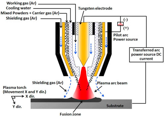
Figure 1.
Scheme showing the plasma cladding systems for coaxial powder feeding case. Reprinted with permission from ref. [14]. Copyright 2021 Elsevier.
We have to underline that recently the focus in HEA investigations has begun to move from homogeneous HEAs to heterogeneous ones [13,14,15,16,17,25,26,27]. Such HEAs contain more that one phase, high specific area of grain boundaries (GB), and interphase boundaries (IBs), as well as other elements of inhomogeneity. The concept of GB phase transitions can be very useful in the development of inhomogeneous HEAs. The GB phase transformations include GB wetting by a second phase (liquid or solid), including formation of thin films of various GB phases [44,45,46,47]. For example, complete or incomplete GB wetting can strongly affect the microstructure, after solidification, of the melted pool during the plasma cladding. Therefore, the GB wetting phenomena taking place during plasma cladding of HEA coatings and their differences in comparison to the previously discussed cases [24,48] are the topic of this review.
2. Grain Boundary Wetting Phase Transitions
In most cases, HEAs contain numerous components. Therefore, the equilibrium phase diagrams for such complicated systems must be constructed in 5–6 or more dimensions. Due to this trouble, we are forced to use a simplified approach. Fortunately, the most important features of GB wetting phase transitions [49] can be described using the simple two-dimensional phase diagram for binary alloys like that shown in Figure 2. Bold lines in this scheme (e.g., solidus, liquidus, solvus, and eutectic lines) depict the bulk phase transitions. The thin lines (like tie-lines at Twmin and Twmax) depict the GB phase transformations. When the solidification of HEAs starts, the composition of an alloy can be found in the phase diagram in the liquid area L. Afterwards, by cooling, it crosses the liquidus line and moves into the two-phase area L + α. In this L + α area the melt is in equilibrium with solid solution α. The solid solution α is based on component A. By following cooling, the amount of solid solution α in this L + α mixture increases and the portion of melt L decreases. The composition of remaining melt L follows the liquidus line. Thus, the melt becomes more and more enriched by component B. Similarly, the composition of solidifying phase α changes along the solidus line. If the concentration of component B in α-phase is low, the solidification finishes at the solidus line. Afterwards, the solidified alloy has only phase, namely the solid solution α. However, the portions of α-phase solidified at the end of the process are enriched by the component B. If we discuss the multicomponent HEAs instead of this simple example of binary alloy, the GB wetting transitions would be more complicated. This is because, for example, an HEA with five components is described by the 5D phase diagram. Therefore, when the liquid alloy L with five components starts to crystallize, it can intersect with not only one binary-phase region, α + L, such as in Figure 2, but numerous multiphase areas. Only afterwards can HEA be completely solid and contain only one α-phase. These multiphase regions can contain more than one liquid phase and one solid phase.
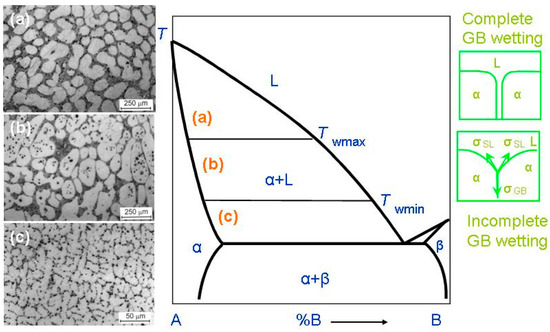
Figure 2.
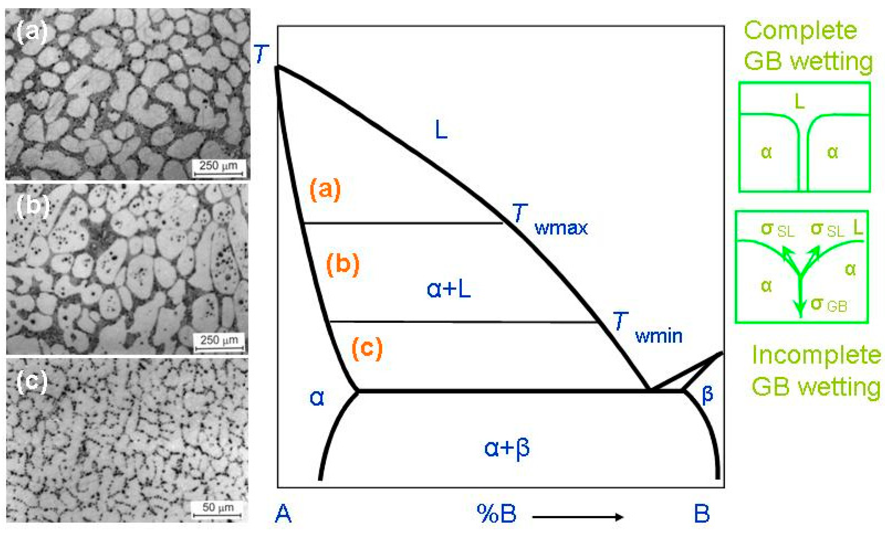
Binary A–B diagram of 3D phases for the discussion of the GB wetting phenomena. Thick lines (solidus, solvus, liquidus, eutectic lines) mark the bulk transitions between 3D phases. Thin lines at Twmin and Twmax mark the tie-lines for the wetting of α/α GBs by the liquid phase, L. On the left-hand side of the figure the micrographs are shown for the L + (Al) polycrystals containing liquid and solid phases. Case (a) shows the alloy structure above Twmax. Here, all (Al)/(Al) GBs are fully wetted. The scheme (b) shows the alloy structure between Twmax and Twmin. Here, some (Al)/(Al) GBs are completely wetted, and other (Al)/(Al) GBs are partially wetted. The scheme (c) shows the alloy structure below Twmin. This sample contains only partially wetted (Al)/(Al) GBs. The respective thermodynamic schemes for complete and incomplete GB wetting are shown right. Here, σGB is the GB energy, σSL is the IB energy, θ is the contact angle. The micrographs are reprinted with permission from ref. [60]. Copyright 2021 MDPI.
When a polycrystal crosses the α + L area of the phase diagram, it contains, first, the interphase boundaries (IBs) between liquid phase, L, and solid phase, α-phase. It also contains the α/α grain boundaries (GBs). The melt, L, contacts the solid phase, α, in the triple junctions (TJs) between GBs and, respectively, two solid/liquid IBs, (see green schemes on the right-hand side of Figure 2). The GB has the energy σGB and each solid/liquid IB has energy 2σSL. If σGB < 2σSL, (see lower scheme in right-hand side of Figure 2), the GB has a non-zero contact angle, θ > 0, with the melt. The GB wetting in this case is partial (or incomplete). The micrograph (c) on the left-hand side of the phase diagram shows an example of how the microstructure of the two-phase α + L polycrystal of the Al–Mg alloy can appear below Twmin. This sample contains only (Al)/(Al) GBs partially wetted by the Mg-rich melt. If the energy of two solid/liquid IBs, 2σSL, is lower than the GB energy, σGB > 2σSL (see upper scheme in Figure 2), then the contact angle becomes equal to zero, θ = 0. In this case, the thick melted layer should separate the solid α-grains, and the GB wetting is complete. The transition between complete and partial GB wetting is described for numerous binary alloys. In these alloys the θ value decreases with growing temperature and becomes zero at a certain temperature, Tw (called the temperature of GB wetting phase transition) [50,51,52]. Above Tw, the GB is completely wetted. The GB wetting phase-transition is in principle two-dimensional one. Nevertheless, it can be of first or second order, similar to phase transformations in the bulk [53,54,55]. In the case of a first-order GB wetting transition, the first temperature derivative of θ, dθ/dT, has a discontinuity at Tw. The dθ/dT suddenly descends at Tw from a certain finite value to zero [50,53,54]. In case of the continuous (second-order) wetting transition in GBs, the dθ/dT value continuously changes with growing T and smoothly reaches zero dθ/dT = 0 at Tw [54,55]. One must take into consideration that the σGB value can strongly depend both on the grain boundary misorientation angle, χ, and on the grain boundary inclination angle, ψ [56]. The dependences of GB energy on χ and ψ, σGB(χ) and σGB (ψ), possess the sharp cusps at certain χ and ψ values [57]. These special misorientation and inclination angles, χ and ψ, are determined by the coincidence site lattices. Due to this fact, the σGB can vary in a rather broad interval of values. Obviously, the lower σGB, the higher GB contact with the liquid phase would be at θ. This means that contact angles in a polycrystal can vary in a very broad interval. Moreover, these contact angles for different GBs should decrease with growing temperature with a different rate. Also, the low-angle GBs have lower σGB than high-angle GBs, and, therefore, the higher Tw values [58]. Actually, the low-angle GBs are not continuous two-dimensional (2D) defects, but consist of arrows of 1D defects, namely dislocations. The GB triple junctions are also 1D defects, and for them, it is lower than for high-angle GBs [59]. Due to these reasons, the spectrum of Tw temperatures in a polycrystal can be quite broad.
Such microstructures of two-phase polycrystals can be seen in Figure 2 (micrographs in the left-hand side). These are the microstructures of the binary Al–Mg alloys. As a result, a conventional phase diagram for 3D-phases gets the additional tie-lines at Twmin and Twmax for 2D GB wetting transformations. At T > Twmax all GBs in a polycrystal are fully wetted and contain, therefore, the melted layer between solid grains. The micrograph (a) on the left-hand side of the phase diagram shows an example of how the microstructure of the two-phase α + L polycrystal of the Al–Mg alloy can appear above Twmax. The micrograph (a) is reprinted with permission from ref. [60]. In this sample, all (Al)/(Al) GBs are completely wetted by the Mg-rich melt. The liquid phase surrounded all solid (Al) grains. The Twmax tie-line describes the GB wetting transformation for GBs with the lowest σGB in a polycrystal. By cooling, the first partially wetted GBs appear below Twmax. Between Twmax and Twmin, the amount of completely wetted GBs decreases with decreasing T. The micrograph (b) on the left-hand side of the phase diagram shows an example of how the microstructure of the two-phase α + L polycrystal of the Al–Mg alloy can appear between Twmin and Twmax. The micrograph (b) is reprinted with permission from ref. [60]. In this sample, some (Al)/(Al) GBs are completely wetted by the Mg-rich melt and other (Al)/(Al) GBs are partially wetted by the liquid phase. At Twmin, the completely wetted GBs disappear. The Twmin tie-line describes the GBs with the highest energy σGB. Below Twmin there are no completely wetted GBs in an alloy, and the polycrystal has only partially wetted GB with θ > 0. The respective example of the Al–Mg alloy is shown in the micrograph (c) on the left-hand side of the phase diagram.
Above Twmax, the liquid phase completely surrounds each solid grain (or crystallite). Thus, solid grains cannot contact each other. It is because the “dry” GBs are thermodynamically forbidden above Twmax. We can see, therefore, how the new GB tie-lines appear in the α + L area of a conventional binary diagram for bulk or 3D phases.
We must underline here that GB wetting phenomena can be observed not only in HEA coatings, but also in the bulk HEAs manufactured by the arc or induction melting in argon or vacuum [61,62,63,64,65,66,67,68,69,70,71,72,73,74,75,76,77,78,79,80,81], electric-current-assisted sintering (ECAS) [82], or additive manufacturing [83].
3. Wetting of Grain Boundaries in the One-Phase HEA Coatings
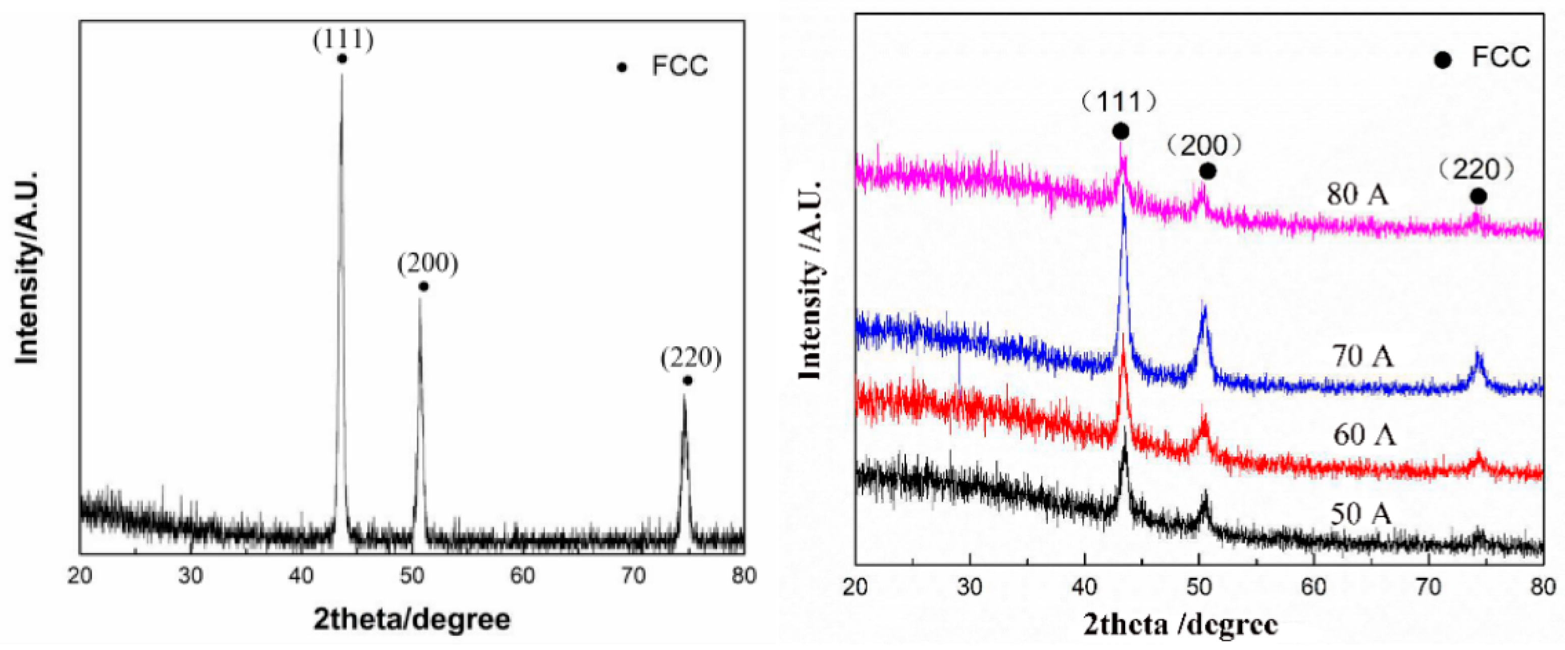
In the work of Cheng et al. [84] the CoCrCuFeNi and CoCrCuFeNiNb high-entropy alloy coatings prepared by plasma transferred arc cladding process were deposited on the Q235 steel substrate. The preplaced powder system was used. The mixed powders were pre-placed onto the surface of a Q235 steel substrate by using glue to form a powder bed with a thickness of 1.7–2.0 mm. Before cladding, the prefabrication samples were preheated in a drying box at 100 °C for 4 h. The X-ray diffraction (XRD) patterns of the CoCrCuFeNi coating contain only the peaks of face-centered cubic (fcc) phase (Figure 3). The XRD patterns of the CoCrCuFeNiNb coating contain the peaks of fcc and Laves phases (Figure 3). The scanning electron microscopy (SEM) permitted the authors to obtain micrographs of these coatings.
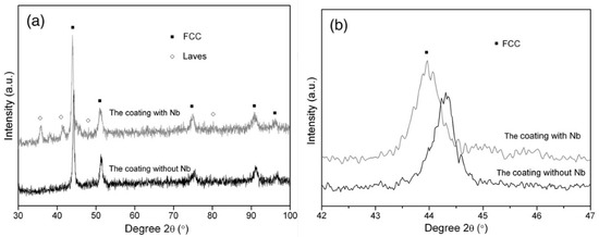
Figure 3.
(a) XRD patterns of the CoCrCuFeNi and CoCrCuFeNiNb coatings; and (b) the detailed scans for the peak of (100) of fcc phase. Reprinted with permission from ref. [84]. Copyright 2014 Elsevier.
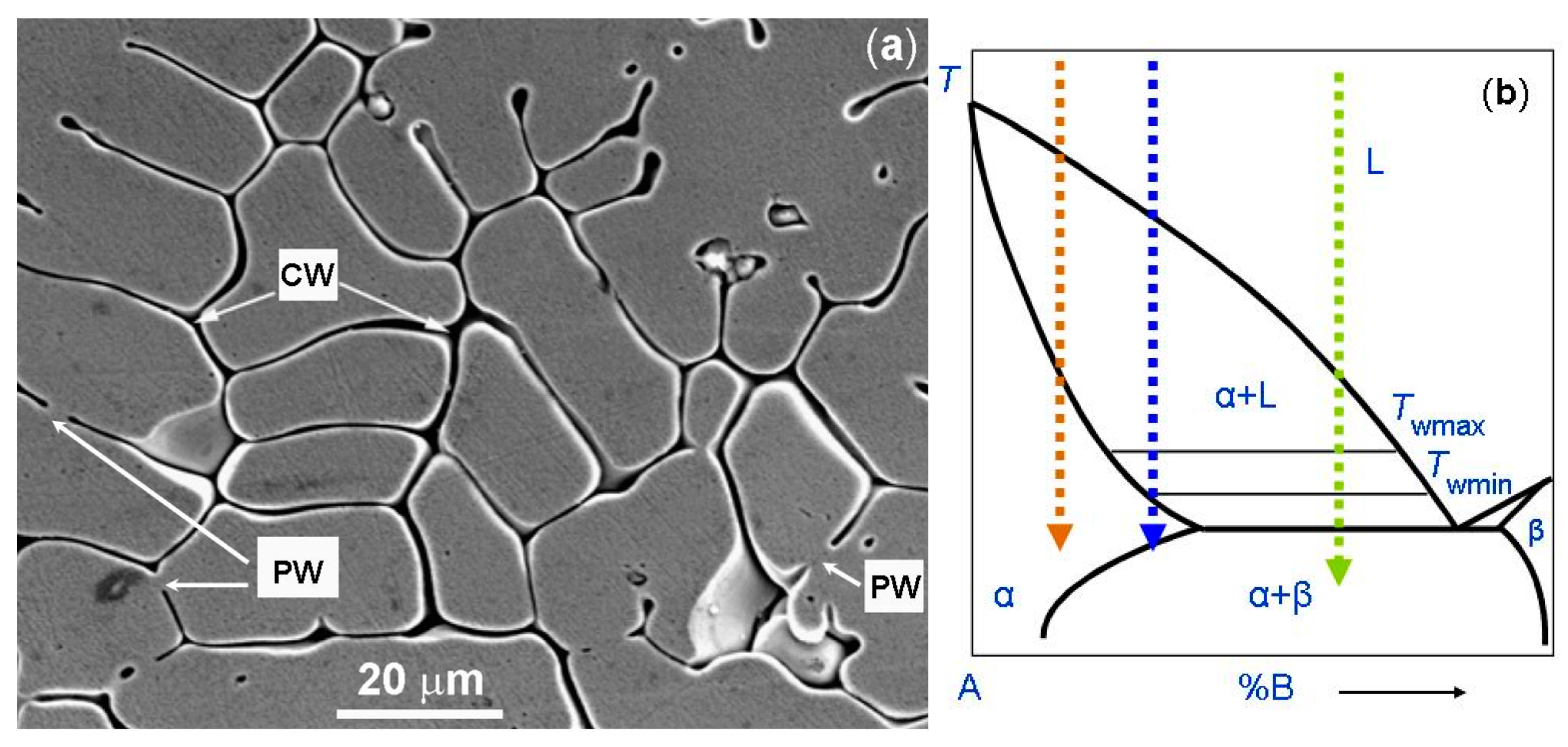
The micrograph of the one-phase CoCrCuFeNi coating is shown in Figure 4a. Figure 4b shows the schematic binary phase diagram. It permits us to explain the GB wetting processes in the microstructure shown in Figure 4a. The dotted red arrow is the cooling trajectory which corresponds to the micrograph in Figure 4a. As mentioned above, if the red trajectory does not intersect with the eutectic transformation line, the grains poor in component B solidify first. Afterwards, the last B-enriched portions of the melt between solid grains solidify. We can see that, in this case, the melt prevents the solid grains to grow together. Thus, these GBs were completely wetted by the B-enriched melt (marked as CW). Only a few GBs are partially wetted and have non-zero contact angle θ with the melt (marked as PW). Moreover, the red trajectory does not intersect with the wetting tie-lines in the scheme. Therefore, almost all GBs remain completely wetted. As a result, after solidification, the CoCrCuFeNi HEAs contained one fcc phase. However, this fcc phase differs in composition in the bulk and in the GBs.

Figure 4.
(a) SEM micrograph of the plasma cladded CoCrCuFeNi HEA coating. Arrows with the symbol CW show the completely wetted GBs. Arrows with the symbol PW show the partially wetted GBs. (b) Schematic of the binary diagram for 3D bulk phases for the explanation of respective GB wetting phenomena. The dotted red arrow shows the cooling trajectory corresponding to the micrographs for the CoCrCuFeNi HEA coating (a). The dotted blue arrow shows the cooling trajectory corresponding to the micrograph for the CoCrFeNiMn HEA coatings. The dotted green arrow shows the cooling trajectory corresponding to the micrograph for the CoCrCuFeNiNb HEA coating. Micrograph 4a is reprinted with permission from ref. [84]. Copyright 2014 Elsevier.
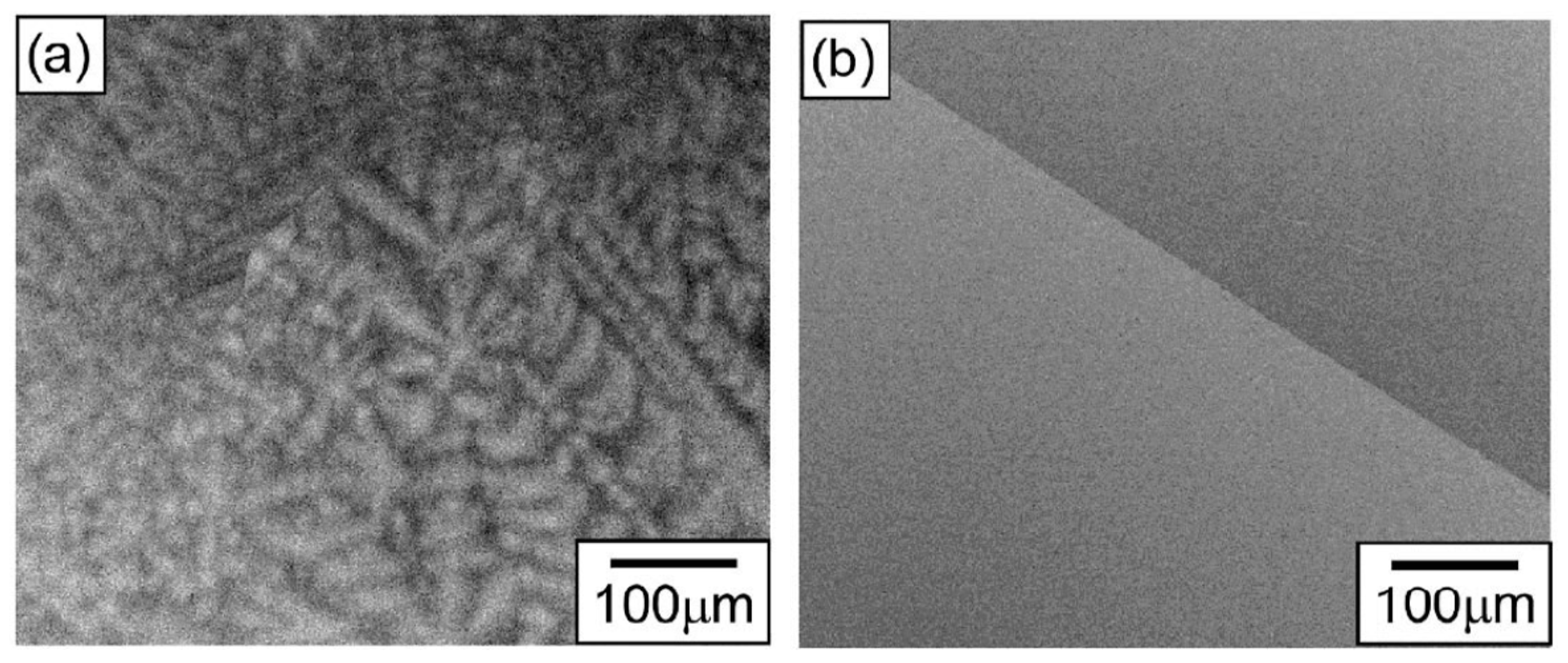
In Figure 5, the SEM micrographs of equiatomic HfNbTaTiZr polycrystal after arc melting are shown in the (a) as-cast, and (b) homogenized state. This example shows how the microstructure of the alloy appears if the GB wetting transition does not take place. The typical B-poor tree-like dendrites solidify first, and the last portions of the liquid from the chaotic polygons (or polyhedra) between the dendrite arms.

Figure 5.
SEM micrographs of equiatomic HfNbTaTiZr polycrystal after arc melting, followed by homogenization treatment at 1773 K for 5 h; (a) as cast, (b) homogenized. Reprinted with permission from ref. [61]. Copyright 2021 Elsevier.
In the work of Gao et al. [13], the CoCrFeNiMn HEA layer was manufactured on the substrate of grey cast iron using the plasma transfer arc cladding. The coaxial powder feeding system was used (see scheme in Figure 1). The plasma arc currents were 50, 60, 70, and 80 A. The plasma torch was at the distance of 10 mm from the exit of the torch, and the scanning speed of the torch was 150 mm/min. The XRD patterns of the CoCrFeNiMn coating contain only the peaks of fcc phase (Figure 6). After deposition (Figure 6 left), the XRD peaks become broader in comparison to the peaks in the homogeneous HEA powder (Figure 6 right) before melting and solidification. It is a sign of composition spread in the solidified one-phase fcc coating (Figure 7).
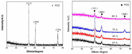
Figure 6.
XRD patterns of CoCrFeNiMn HEA powder (left) and plasma cladded CoCrFeNiMn HEA coatings (right) deposited at plasma arc currents of 50, 60, 70, and 80 A. Reprinted with permission from ref. [13]. Copyright 2021 MDPI.
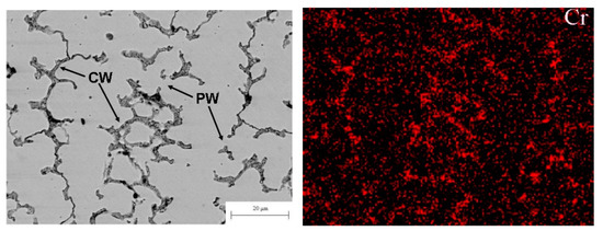
Figure 7.
(left) SEM micrograph of the plasma cladded CoCrFeNiMn HEA coating. Arrows with the symbol CW show the completely wetted GBs. Arrows with the symbol PW show the partially wetted GBs. (right) EDS map of chromium in the middle part of the CoCrFeNiMn coatings prepared at plasma arc current of 70 A. Micrographs are reprinted with permission from ref. [13]. Copyright 2021 MDPI.
The micrograph of the one-phase CoCrCuFeNi HEA coating is shown in Figure 7 (left). Similar to the micrograph shown in Figure 4a for the CoCrCuFeNi HEA coating, the alloy contains the areas solidified first (they appear bright in the micrograph), and areas solidified at the end of the reaction. The latter appear dark grey in the micrograph and are enriched by Cr as shown in energy dispersive electron spectroscopy (EDS) map in Figure 7 (right). Different to the micrograph in Figure 3a, the matrix grains are not completely surrounded by the Cr-rich layers. The cooling trajectory corresponding to Figure 7 is schematically shown by a dotted blue line in the scheme in Figure 4b with the arrow at the end. As the dotted trajectory does not cross the line of eutectic transition, the grains which are poor in chromium solidify first. The last Cr-enriched portions of the melt between Cr-poor grains solidify at the end of cooling. It is visible in the micrograph that some Cr-poor grains were not grown together during the solidification forming the GBs. Therefore, such GBs are completely wetted by the chromium-rich melt (CW). Other GBs are partially wetted by the chromium-enriched liquid phase (PW). The respective blue dotted trajectory (see Figure 4b) does not intersect with the eutectic line. However, it intersects with the wetting tie-line at Twmax in the scheme in Figure 4b. Therefore, some GBs are completely wetted (CW) and other GBs are only partially wetted (PW) by the melt. Nevertheless, after solidification, the CoCrCuFeNi HEA contained only one fcc phase. This fcc phase has a different composition in bulk and in GBs. This fact leads to the broadening of XRD peaks of the fcc phase. We can see that substitution of Cu in the CoCrCuFeNi equimolar one-phase fcc HEA [84] with Mn leads to the appearance of partially wetted GBs among completely wetted ones [13] and to the shift of the solidification route from the position marked in the scheme Figure 3b by the red dotted arrow to the position marked by the blue dotted arrow.
In the work of Xing et al. [85], the HEA coatings with the composition (CoCrFeNi)94Ti1.5Al4.5 were manufactured on the Q235 steel substrate by plasma spraying and plasma cladding methods. The idea of this work was to clarify how the small additions of titanium and aluminum, as well as differences in microstructure, influence the corrosion resistance of an HEA coating on the Q235 steel substrate. The coatings contained only one phase with fcc lattice and different composition in the grains solidified at the beginning and in the intergranular layers. The layers solidified at the end of the crystallization process wetted the fcc/fcc grain boundaries. In ref. [86], the composite HEA coatings with the composition FeCoNiCr + x(TiC) (x: mass fraction; x = 5, 10, 15) were deposited by the PTA-BX400A machine for plasma cladding with coaxial powder feeding. The coating thickness was approximately 10 mm. The FeCoNiCr coating with x = 0 contained only one phase with fcc lattice. The FeCoNiCr-TiC composite coatings contained the TiC, fcc, and carbide phases. The last portions of a melt during solidification were rich in chromium. About a half of the fcc/fcc GBs were completely wetted by the Cr-rich melt, the other half of the fcc/fcc GBs were partially wetted.
In the work of Peng et al. [87], the HEA composite coatings, FeCoCrNi, with the addition of 20% WC-reinforcing particles were prepared by two different cladding methods, namely laser and plasma cladding. The plasma cladded coatings contained the one-phase fcc matrix. Similar to the microstructures shown in Figure 3 and Figure 7, the one-phase fcc matrix consisted of elongated grains (they were Cr-depleted) with wetting Cr-rich layers between them. The shape of fcc grains, as well as the portion of completely/incompletely wetted GBs, changed with depth in the coating. In some cases, only the partial wetting of GBs in the Cr-depleted fcc matrix by the Cr-enriched fcc phase was observed, for example in the CoCrFeMnNi HEAs deposited by the plasma cladding [88].
One can also find the similar behavior in GB wetting in HEA coatings deposited by laser cladding which contained a single phase with variable composition in the bulk of the grains and in the GB wetting layers. Here, we can mention the HEA coatings FeNiCoCrMox (x = 0, 0.15, 0.20, 0.25) on the 316 stainless steel substrate [89], the CoCr2FeNiMox HEA with different Mo content from x = 0 to 0.4 [90], the AlCoCrFeNiSix HEAs with from x = 0 to 0.5 [91], the CrFeNiNbTi alloy [92], the CoCrCu1−xFeNix HEA containing x from 0 to 0.5 [93]. We can see that, different to the plasma cladding, for the HEAs deposited by laser cladding, the optimization of composition by changing the concentration in small steps was frequently used.
4. GB Wetting in the HEA Coatings Containing Two or More Phases
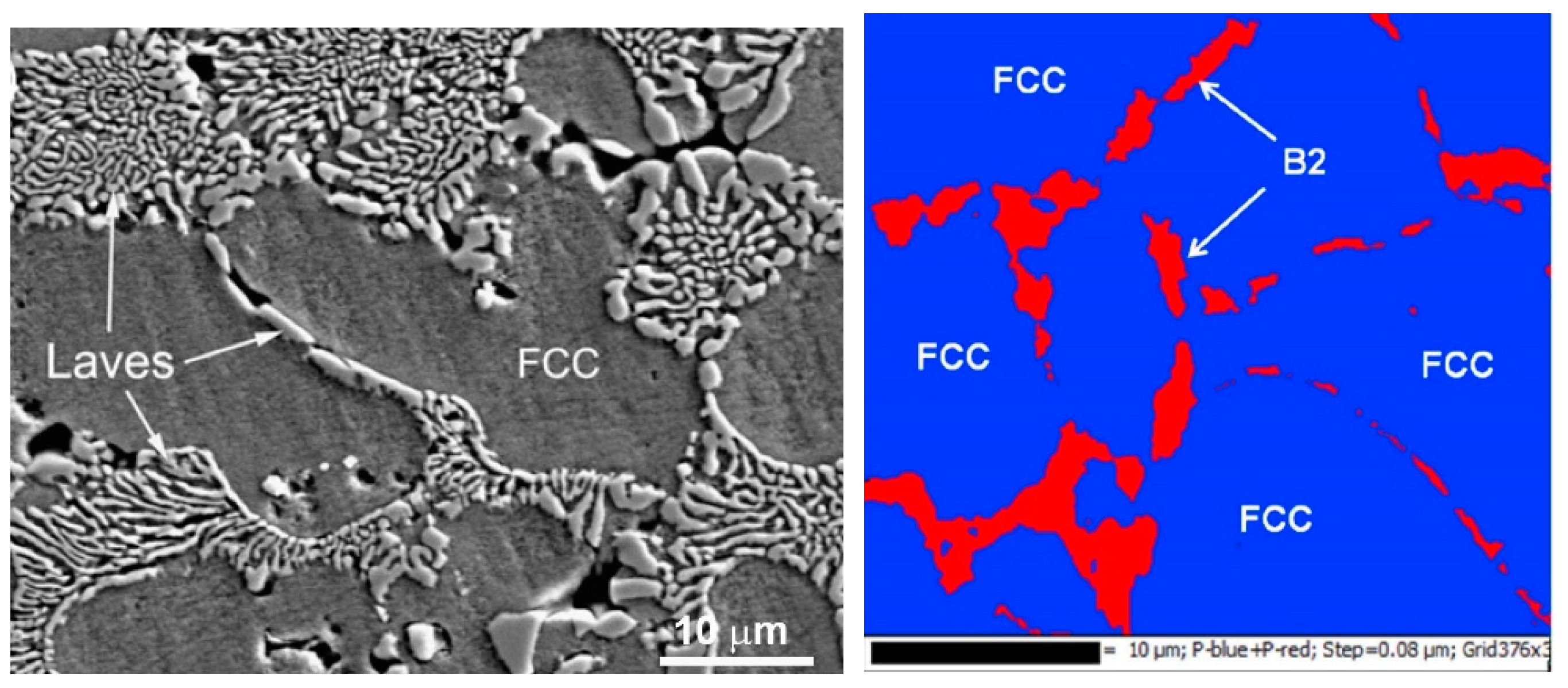
The work of Cheng et al. [84] provides another example when the solidified HEA contains two different phases, namely the fcc and Laves phases (see also earlier work [41]. When the CoCrCuFeNi equimolar HEA was substituted with the CoCrCuFeNiNb equimolar one, the Laves minor phase appeared in the XRD pattern additional to the fcc major one. As a result (see micrograph in Figure 8), the fcc grains of the matrix phase are completely surrounded by the solidified eutectic containing the fcc + Laves mixture. This case differs from the case of CoCrCuFeNi equimolar HEA (see the micrograph in Figure 3a and the scheme in Figure 3b, blue dotted trajectory). Namely, now the solidification trajectory (dotted green arrow) does not finish in the α-area after the cooling. On the contrary, it crosses the line of eutectic transition L → α + β in the scheme. In the real CoCrCuFeNiNb alloy this eutectic reaction is L → fcc + Laves phases. At the end of solidification, the last portions of the liquid completely wet all GBs between fcc grains of a solid solution. Afterwards, they decompose following the reaction L → α + β. We have to underline here that the micrograph shown in Figure 8 contains only completely wetted fcc/fcc GBs. This means that in the CoCrCuFeNiNb HEA, not only is the dotted trajectory shifted to the right in comparison with CoCrCuFeNi equimolar HEA, but the Twmax tie-line was also shifted to the lower temperatures. As a result, the incompletely wetted fcc/fcc GBs did not form at all during the solidification. Similar structures and GB wetting by Laves phase were also observed in CoCrCuFeNiNb HEAs in ref. [41].
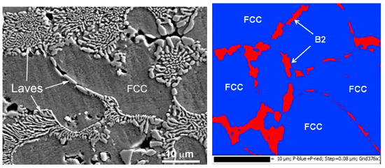
Figure 8.
(left) SEM micrograph of the plasma cladded CoCrCuFeNiNb HEA coating. Micrograph is reprinted with permission from ref. [84]. Copyright 2014 Elsevier. (right) EBSD phase map of the Co25Cr25Cu12.5Ni25Al12.5 (at.%) HEA. EBSD phase map shows that the Ni–Al-rich phase in the intergranular region is the B2 phase. Micrograph is reprinted with permission from ref. [94]. Copyright 2014 Elsevier.
The phase which wets the fcc/fcc GBs in HEAs cannot exclusively be Laves phase. Thus, in the work of Wang et al. [94], the Co25Cr25Cu12.5Ni25Al12.5 (at.%) HEAs were produced by the spark plasma sintering. The XRD pattern contains the fcc peaks as well as the peaks of the B2 phase. The electron backscattering diffraction (EBSD) combined with the SEM images shows that the minor B2 phase is positioned in the fcc/fcc GBs (Figure 8, right). Moreover, the layers of the B2 phase are not continuous. They do not fully separate the grains of the fcc solid solution in the matrix. This case corresponds to the incomplete GB wetting by the last portions of the melt during solidification. In other words, the green dotted line in the scheme in Figure 3b perfectly describes the situation in the Co25Cr25Cu12.5Ni25Al12.5 (at.%) HEAs [94]. This means that the Twmax and Twmin temperatures are indeed higher than the temperature of eutectic transformation as it is shown in the scheme in Figure 3b.
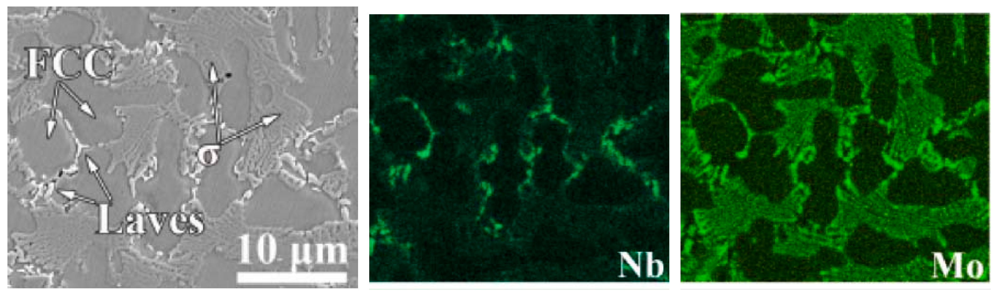
In some cases, the plasma cladded HEA coatings contain more than one phase wetting the GBs. A good example is the Co26.57Ni26.81Cr17.71Mo7.63Nb2.40B12.67Si6.22 (at.%) HEAs deposited by a plasma cladding PW3L machine at a gun speed of 300 mm/s and a feeding rate of 15 g/min [95]. The XRD patterns contain the peaks of the fcc major phase and two minor phases, namely the Laves phase and σ-phase. The SEM micrographs and EDS mapping (Figure 9) shows that the fcc grains are completely surrounded by the layers of Laves phase and σ-phase. The Laves phase is enriched by molybdenum and Co-depleted. The σ-phase is enriched by niobium and Cr-depleted.
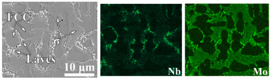
Figure 9.
SEM micrograph and respective EDS composition maps for the distribution of Nb and Mo for the Co26.57Ni26.81Cr17.71Mo7.63Nb2.40B12.67Si6.22 (at.%) HEA deposited by the plasma cladding. Micrograph is reprinted with permission from ref. [95]. Copyright 2022 Elsevier.
The matrix phase in the plasma-cladded HEA coatings is not always the fcc one. It can also have the base-centered cubic (bcc) lattice, such as, for example, in the Fe19.49Co19.49Ni19.49Al19.49Cu19.49Si2.55 (at.%) HEA coating [96]. It was deposited by the A PAW-160 plasma cladding machine. The XRD pattern revealed that this HEA coating contained three solid solution phases, one with bcc and two with fcc lattice. Figure 10 (left) shows the SEM micrograph of this plasma-cladded Fe19.49Co19.49Ni19.49Al19.49Cu19.49Si2.55 (at.%) HEA coating [96]. Almost all bcc matrix grains are surrounded by the GB layers of fcc1 and fcc2 phases. They are copper-enriched (Figure 10, right). Some of the GB layers of fcc1 and fcc2 phases are interrupted. These bcc/bcc GBs were incompletely wetted by the melt at the last stage of solidification.
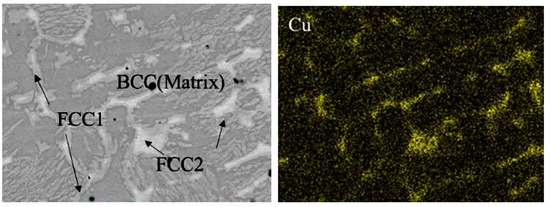
Figure 10.
(left) SEM micrograph of the plasma cladded Fe19.49Co19.49Ni19.49Al19.49Cu19.49Si2.55 (at.%) HEA coating. (right) EDS map of copper. Micrographs are reprinted with permission from ref. [96]. Copyright 2017 Elsevier.
In the work of Peng et al. [97], the WC composite coatings contained the FeCoCrNi HEA matrix and spherical WC-reinforcing particles with various mass fractions (0.1, 0.2, 0.4, 0.6, 0.7) were deposited by plasma cladding on steel substrates. The pure FeCoCrNi coating (without WC addition) consisted of a single fcc phase. At 0.1 WC mass fraction, the XRD patterns did still now show the peaks of WC phase or other carbides. At WC mass fraction of 0.2, the XRD peaks of composite of M6C phase carbide appeared, namely the Fe3W3C phase. The height of this peak grew with the increase of WC content. It means that the amount of the Fe3W3C carbide grew as well. At low WC content the microstructure with wetted fcc/fcc GBs was similar to that shown in Figure 3 and Figure 7.
In the work of Wang et al. [98], the (CoCrFeMnNi)85Ti15 HEA coating was manufactured on the Q235 steel substrate via plasma cladding. Close to the substrate, the HEA coatings begin with a planar plate of fcc phase which is about 30–40 μm thick. Then, the area follows, which is about 1 mm thick. Here the fcc grains are equiaxial. Almost all boundaries between fcc grains in the matrix are completely wetted by the mixture of bcc and σ phases. In the upper coating area, the fcc grains are elongated, but complete GB wetting is conserved.
In the work of Wang et al. [99], the HEA coatings with the composition CoCrFeMnNiTix (x = 0, 0.3, 0.65 and 1) were manufactured using plasma cladding. With increasing titanium concentration from x = 0 to 1, the phase composition of CoCrFeMnNiTix coatings changes. At low x, they contain only one phase with fcc lattice. With increasing x, the complicated structure with hybrid phases with fcc and bcc lattice, as well as σ-phase with equiaxed and/or snowflake-like grains, appear. The grain size also gradually increased with increasing Ti content. The wetting of boundaries between fcc grains by the mixture of bcc and σ-phases is especially well-pronounced in HEAs with x = 0.65 and 1. This result correlates well with the data obtained in ref. [98].
We can compare the GB wetting in multiphase HEAs deposited by plasma cladding with that in the HEA coatings manufactured by laser cladding. The transition from HEAs containing one phase to those containing two phases took place in the AlxCrFeCoNiCu laser cladded coating (x = 0, 0.1, 0.3, 0.5, 0.7, 0.8, 1.0, 1.2, 1.5, 1.8, or 2.0) [100]. The AlxCrFeCoNiCu HEA samples with x = 0, 0.1, 0.3 contained only the fcc phase with different composition in GB wetting layers and in the bulk. The samples with x = 0.7, 0.8, 1.0 contained the same fcc phase and, additionally, to bcc phases (bcc1 and bcc2). The matrix grains had fcc structure, the last portions of the melt before complete solidification wetted the boundaries between fcc grains. Afterwards, they decomposed in the fcc + (bcc1,bcc2) mixture [100]. The CoCrFeNiAlxMn(1−x) dual-phase coatings give other example of HEAs which first contain one phase and then two phases [101]. The multiphase state HEA coatings deposited by laser cladding was observed in TiZrAlNbCo HEAs [102], ceramic particle reinforced FeCoNiCrMnTi HEAs with fcc matrix and bcc-phase, Laves phase and titanium nitride in the grain boundary wetting layers [103], and CoCr2FeNb0.5NiSi coating with Laves phase, fcc-phase and CrO2 [104].
5. Influence of Distance from the Surface on GB Wetting in HEA Coatings
The plasma cladded coatings are usually quite thick, up to several mm. Respectively, the conditions for the GB wetting can be different through the full thickness of a coating. Figure 11 shows the SEM micrograph through the entire Fe19.49Co19.49Ni19.49Al19.49Cu19.49Si2.55 (at.%) HEA plasma cladded coating on the AISI 1045 steel as a substrate [96]. The micrograph in Figure 10 shows only the part of the central region of this thick coating. It is visible in Figure 11 that in the bottom part, not all bcc/bcc GBs were wetted by the melt during solidification. One of the reasons could be the partial dissolution of a steel substrate in the melted coating. Moreover, it is also visible that the distribution of fcc1 and fcc2 phases in bcc/bcc GBs also depends on the depth.
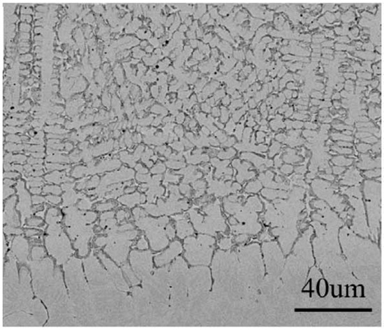
Figure 11.
SEM micrograph through the entire FeCoNiAlCuSi HEA plasma cladded coating. Micrograph is reprinted with permission from ref. [96]. Copyright 2017 Elsevier.
In the upper part of Figure 12, the cross-section of the Cr20Cu20Fe20Ni20Al20 HEA coating is shown. This composite Cr20Cu20Fe20Ni20Al20 coating was manufactured by plasma arc cladding with a synchronized powder feeding (see Figure 1). It was reinforced by the titanium carbonitride particles formed in the plasma torch from the Ti powder and g-C3N4 powder. The coating was deposited on the Q235 steel substrate. The matrix of this HEA coating had bcc structure. The flat wetting layers in bcc/bcc GBs contained mainly the fcc and B2 phases (see lower part of Figure 12). One cannot attribute the faceted Ti(C,N) particles to GB wetting phase. Nevertheless, they were also mainly located in the bcc/bcc GBs or in the GB triple junctions. One can clearly see in the upper micrograph in Figure 12 that the coating close to the steel substrate does not contain any wetted GBs at all. Partially and fully wetted GBs do not appear close to the substrate, but first at a distance of about 10–20 μm.

Figure 12.
SEM micrographs for the cross section of the Cr20Cu20Fe20Ni20Al20 HEA composite coating reinforced with particles of titanium carbonitride on the Q235 steel substrate. (upper part) The image of macro-morphology; (lower part) BSE image of the upper-middle area. Micrographs are reprinted with permission from ref. [14]. Copyright 2021 Elsevier.
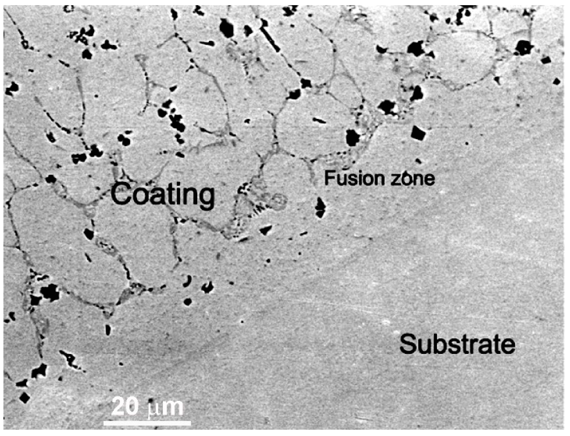
In the work of Cheng et al. [42], the CoCrCuFeNi equimolar HEA coatings were deposited with plasma cladding on the Q235 steel substrate. The coatings also contained the different amounts of TiC and TiB2-reinforcing particles. The matrix was formed by fcc phase. The fcc/fcc GB wetting layers contained, after solidification, the bcc phase (dark grey phase between light grey matrix grains in Figure 13). The TiC and TiB2 reinforcing particles are faceted and appear almost black in Figure 13. Similar to the micrographs in Figure 12, the fusion zone close to the substrate dose not contain any wetted fcc/fcc GBs. They first appear at a distance about 20 μm from the substrate.
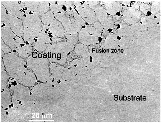
Figure 13.
SEM image of the CoCrCuFeNi equimolar HEA coatings reinforced by the TiC and TiB2 particles. The substrate is a Q235 steel. The fcc matrix in the HEA coating appears light grey, the bcc phase in the GBs appears dark grey. The TiC and TiB2 particles appear black. Micrograph is reprinted with permission from ref. [42]. Copyright 2021 Elsevier.
In the work of Lu et al. [105], the CrCuFexNiTi HEA layers were deposited on Q235 substrate by plasma cladding. In this HEA coating, the gradient of component content formed due to gradient in temperature, as well as dilution of the steel substrate. It consisted of bcc matrix grains and rather thick fcc phase layers, completely wetting the bcc/bcc grain boundaries. In the area between the coating and steel substrate, the planar crystals of γ-Fe-based solid solution, as well as of Fe2Ti intermetallic compound, are visible.
In the work of Zhou et al. [1], the CoNiCuFeCr HEA coatings were deposited as a protection layer with improved corrosion and wear resistance on the Q235 steel. The plasma cladding process with melting of the prepared powder mixture on the substrate was used. The microstructure was different at different depths. The perfect structure with all GBs in the Cu-depleted fcc matrix completely wetted by the Cu-rich last portions of the melt (similar to that shown in Figure 3 and Figure 7) can be observed in the bottom part of the coating. In the top part, some GBs in the Cu-depleted fcc matrix become partially wetted.
6. GB Wetting in the Reinforced HEA Coatings
In some cases, the plasma cladded HEA coatings are reinforced with particles of carbides, nitrides, borides, or oxides. We already saw two such examples in Figure 12 and Figure 13. Usually, these particles are added to the mixture of metallic powders before cladding. Unlike the metallic components they do not melt under plasma torch. However, they redistribute in the melt during its solidification. As a result, the reinforcing carbides, nitrides, borides, or oxides also non-trivially interact with the liquid phase which completely or incompletely wets the grain boundaries between HEA matrix grains.
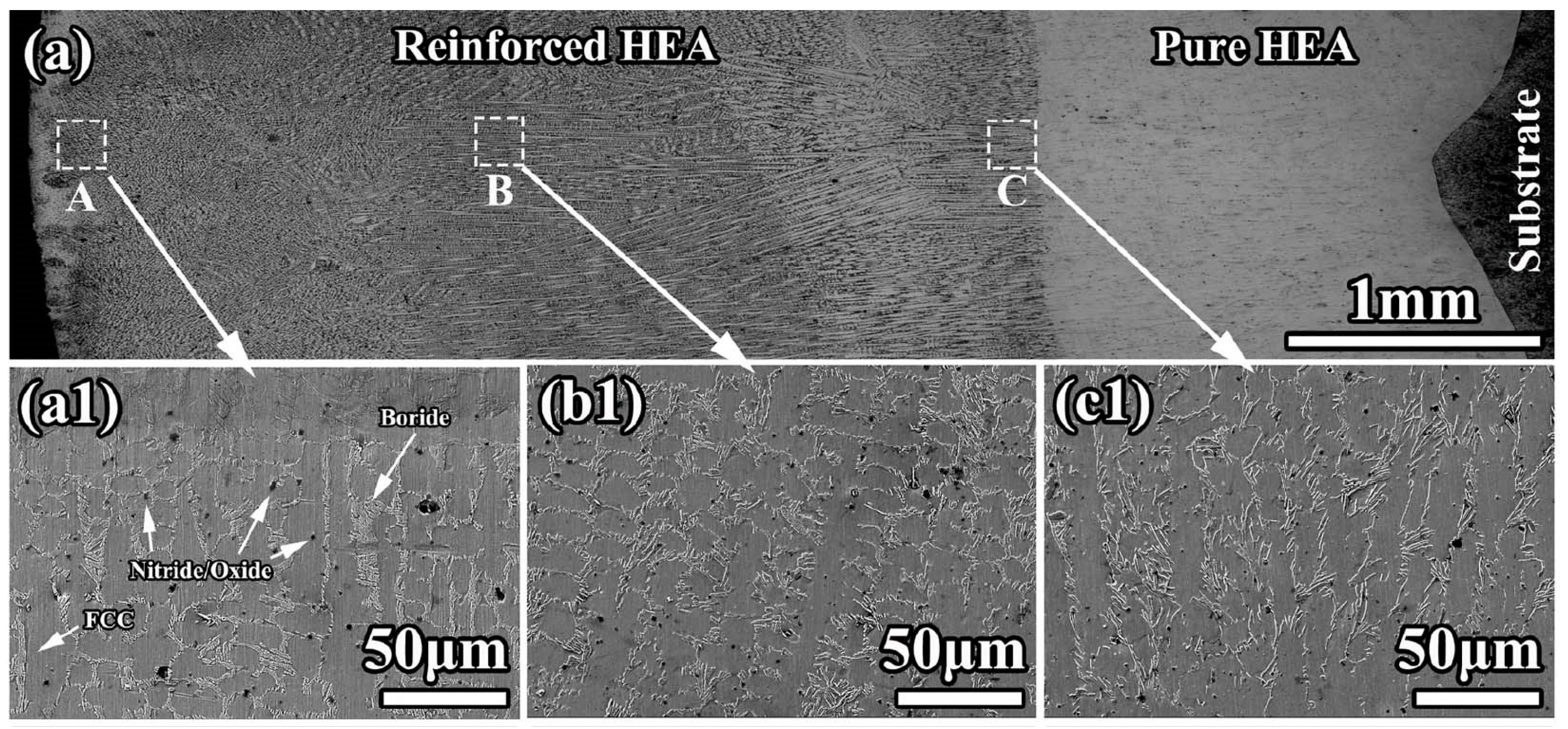
A good example can be found in the ref. [106]. The multi-ceramics reinforced CoCrFeMnNi HEAs coating was prepared in situ on the polished substrate by plasma cladding using the equal atomic ratio CoCrFeMnNi HEAs, Al, TiO2, and BN powders. The boron and iron were added to reach higher boron content in the coating. Iron and silicon were added to increase formability of HEA coatings. The HEA coatings were deposited on the Q235 steel substrate. The non-reinforced pure HEA was deposited as an interlayer between reinforced HEA and substrate. This method permitted to prevention of the dilution of base material. The intermediated pure HEA layer also allowed to improvement of the bonding strength between the reinforced HEA coating and the substrate.
The XRD patterns of plasma cladded pure HEA coatings only contained the lines of the phase with fcc lattice. The reinforced HEA coating also contained mainly the fcc solid solution. However, the reinforced HEA also had the titanium nitride and Cr2B intermetallic. The lattice constant of the fcc solid solution (being the matrix phase) in the reinforced HEA coating was slightly different than in the pure HEA. This is because the titanium and aluminum atoms dissolve in the fcc solid solution during the plasma cladding. The atomic radii of titanium and aluminum atoms are larger than those of CoCrFeMnNi HEA components resulting in lattice expansion.
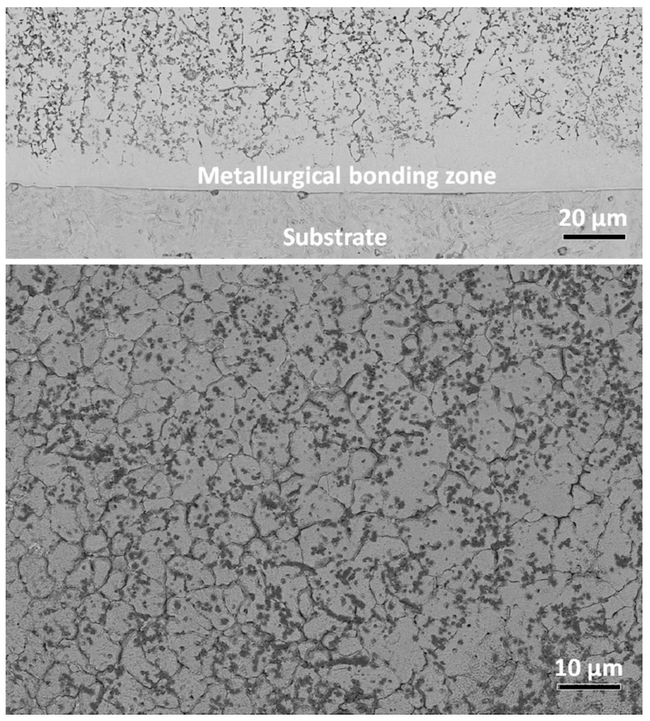
The resulting microstructure is shown in Figure 14. The cladded coating had no pores or cracks. The coating possessed good metallurgical bonding with substrates. The composite coating had pure a HEA interlayer (thickness ≈ 1.6 mm, seen in Figure 14(c1)) and a reinforced HEA overlayer. The planar structure formed at the bottom of the interlayer (Figure 14(a1)). It has a thickness of ~30 μm. According to the EDS results, the fcc matrix grains were rich in cobalt, chromium, and iron. The GB wetting areas were rich in manganese and nickel. It is clearly visible that the morphology of GB wetting layers, as well as the portion of completely and incompletely wetted fcc/fcc GBs, is different in different areas of the composite coating.

Figure 14.
(a) Light micrograph for the cross-section of composite coating; (a1,b1,c1) are the SEM micrographs showing the morphology in the A, B, and C areas in (a). Reprinted with permission from ref. [106]. Copyright 2022 Elsevier.
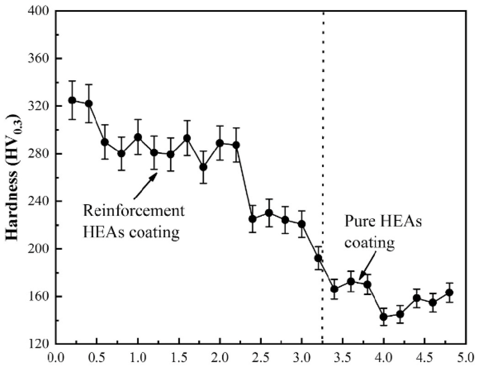
Figure 15 shows the microhardness distribution in the cross section of reinforced HEA coating [106]. The hardness of the reinforced HEA composite coating decreased from 320 HV0.3 to 240 HV0.3 with increasing depth. Nevertheless, both these values were higher than the hardness of the pure HEA interlayer, namely 170 HV0.3. The multiphase TiN-Al2O3-Cr2B ceramics synthesized in situ are responsible for dispersion strengthening. By the way, the dissolved titanium and aluminum promoted the solid solution strengthening of the matrix. Also, the amount of ceramic particles decreases from top to bottom. This fact also leads to the hardness decrease.
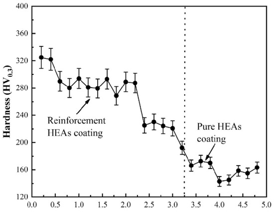
Figure 15.
Microhardness distribution of reinforced HEA coating. Reprinted with permission from ref. [106]. Copyright 2022 Elsevier.
In ref. [107] the AlCoCuFeMnNi HEA and composite AlCoCuFeMnNi HEA reinforced by the CeO2 particles were deposited via plasma cladding on carbon steel substrates. The coatings contained two bcc phases. The copper- and nickel-depleted bcc phase was the major phase, and the copper- and nickel-enriched bcc phase was the minor one. The grain boundaries in the major phase with bcc lattice were fully or partially (about 50:50) wetted by a layer of minor bcc-phase. The addition of fine CeO2 particles improved the properties of a composite but did not significantly change the ratio between completely and incompletely wetted bcc/bcc GBs.
7. GB Wetting in HEA Coatings after Laser Remelting
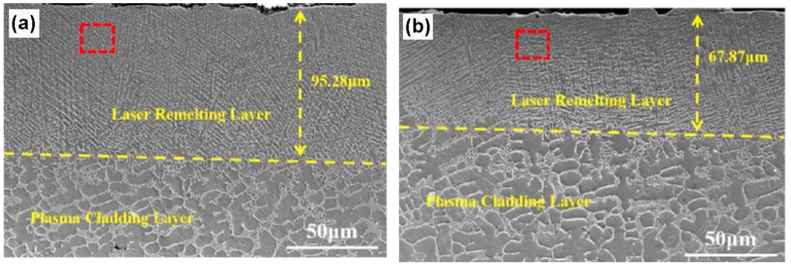
The HEA coatings deposited by plasma cladding can be partially laser remelted afterwards as in ref. [108]. The cladding process of the (FeCoCrNi)75Nb10B8Si7 coatings was divided into two steps, and occurred in an argon atmosphere. A coaxial powder feeding plasma cladding system (CHILLER GW-02ACL) was used to prepare the coating. These samples were called PC. This cladding coating was cooled to room temperature in an Ar atmosphere and polished with sandpaper. Then, a fiber diode laser (LSJG-BGQ-2000) was used to perform laser remelting with a laser power of 2000 W, a laser beam diameter of 2.5 mm, and the laser scanning speed of 7 m/min and 8 m/min. The samples were respectively called LRM7 and LRM8.
XRD patterns of the PC coating contained only the phase with bcc lattice, whereas the LRM7 and LRM8 coatings consisted of the mixture of two phases with bcc and fcc lattices. In Figure 16, it is visible that in the plasma cladding layer (lower parts of the micrographs), the grains of the bcc phase were completely or incompletely surrounded by the solidified portions of the melt, as in Figure 3. The laser remelting completely changes the microstructure, the grain size decreases and the fcc grains are completely surrounded by the bcc layers.

Figure 16.
SEM images showing the cross-sections of the (FeCoCrNi)75Nb10B8Si7 coatings. (a) LRM7. (b) LRM8. Reprinted with permission from ref. [108]. Copyright 2021 Elsevier.
8. Conclusions
- The grain boundary wetting phase transitions can strongly influence the structure of high-entropy alloys deposited by plasma cladding. During the plasma cladding the grain boundaries (GBs) can be completely or partially wetted by the melt.
- Even in the case of a HEA containing only one (fcc or bcc) phase, then at the end of crystallization, the solid (fcc or bcc) grains are depleted with some components. On the contrary, the remaining liquid phase is enriched by these components and completely or partially wets the GBs.
- HEAs can also contain two or more phases. In this case, the last portions of the melt during solidification can transform into a mixture of two or more solid phases in a eutectic decomposition. Then, the liquid GB layers after crystallization transform in the solid GB interlayers consisting of second, third etc. solid phases.
- In some cases, the plasma cladded HEA coatings are reinforced with particles of carbides, nitrides, borides, or oxides. They do not melt under plasma torch, but interact in the complicated way, with solidifying GB layers of a melt.
- The plasma cladded HEA coatings are usually rather thick. The microstructure and GB wetting conditions can significantly change over the thickness of theses coatings. Especially interesting is the process of later remelting of HEAs by the laser beam. It can also modify the conditions for GB wetting.
- Usually, the bulk phase transformations are the important instruments in the hands of materials scientists and engineers, permitting them to tailor the structure and properties of materials. The most famous phase transformations here are the αFe-γFe, αTi-βTi, αTi-ωTi, βCo-ωCo et al. However, we can see from the discussed examples of plasma cladded HEA coatings that the grain boundary wetting transitions can also be a powerful instrument to tailor the structure and properties of materials, in particular for energy conversion and storage applications.
- Moreover, we have to underline here that the thick (at least few μm) grain-boundary layers of the second phase(s) can appear in HEAs during crystallization of the melt in all synthesis technologies. The formation of such continuous or discontinuous GB layers of a second phase(s), or even just the layers of the same phase with different composition, can strongly modify the properties of HEAs. Thus, the understanding of chemistry, physics, or thermodynamics of the GB wetting transformations in HEAs will open the way for the purposeful control and tailoring of HEA properties. Such detailed knowledge of GB wetting processes in HEAs could seriously increase their application areas.
Author Contributions
Conceptualization, B.S., G.A.L., A.S. and A.K. (Anna Korneva); Methodology, A.K. (Anna Korneva), A.S., A.K. (Alexei Kuzmin), B.S., A.S., A.G. and N.V.; Formal analysis, A.K. (Alexei Kuzmin) A.K. (Anna Korneva), A.S., L.K. and N.V.; Writing—original draft preparation, A.K. (Alexei Kuzmin), A.K. (Anna Korneva), A.S., and N.V.; Writing—review and editing, B.S.; Supervision, A.K. (Anna Korneva) and B.S.; Project administration, A.K. (Anna Korneva) and B.S.; Funding acquisition, A.K. (Anna Korneva) and B.S. All authors have read and agreed to the published version of the manuscript.
Funding
This research was funded by the Russian Ministry of Science and Higher Education (contract no. 075-15-2021-945 grant no. 13.2251.21.0013). Support from the University of the Basque Country (project GIU19/019) and from the Basque Government (project IT1714-22) is also acknowledged.
Institutional Review Board Statement
Not applicable.
Informed Consent Statement
Not applicable.
Data Availability Statement
All the data required to reproduce these experiments are present in the article.
Acknowledgments
The Institute of Solid State Physics, University of Latvia, as a center of excellence, has received funding from the European Union’s Horizon 2020 Framework Programme H2020-WIDESPREAD-01-2016-2017-TeamingPhase2 under grant agreement no. 739508, project CAMART2.
Conflicts of Interest
The authors declare no conflict of interest.
Abbreviations
| bcc | body centered cubic lattice |
| fcc | face centered cubic lattice |
| EBSD | electron backscattering diffraction |
| EDS | energy dispersive electron spectroscopy |
| GB | grain boundary |
| HEA | high entropy alloy |
| IB | interphase boundary |
| SEM | scanning electron microscopy |
| TJ | triple junction |
| TEM | transmission electron microscopy |
| XRD | X-ray diffraction |
References
- Zhou, H.; He, J. Synthesis of the new high entropy alloy and its application in energy conversion and storage. Front. Energy Res. 2020, 8, 73. [Google Scholar] [CrossRef]
- Amiri, A.; Shahbazian-Yassar, R. Recent progress of high-entropy materials for energy storage and conversion. J. Mater. Chem. A 2021, 9, 782–823. [Google Scholar] [CrossRef]
- Liu, H.; Syama, L.; Zhang, L.; Lee, C.; Liu, C.; Dai, Z.; Yan, Q. High-entropy alloys and compounds for electrocatalytic energy conversion applications. SusMat 2021, 1, 482–505. [Google Scholar] [CrossRef]
- Fu, M.; Ma, X.; Zhao, K.; Li, X.; Su, D. High-entropy materials for energy-related applications. iScience 2021, 24, 102177. [Google Scholar] [CrossRef]
- Cantor, B.; Chang, I.T.H.; Knight, P.; Vincent, A.J.B. Microstructural development in equiatomic multicomponent alloys. Mater. Sci. Eng. A 2004, 375–377, 213–218. [Google Scholar] [CrossRef]
- Yeh, J.-W.; Chen, S.-K.; Lin, S.-J.; Gan, J.-Y.; Chin, T.-S.; Shun, T.-T.; Tsau, C.-H.; Chang, S.-Y. Nanostructured high-entropy alloys with multiple principal elements: Novel alloy design concepts and outcomes. Adv. Eng. Mater. 2004, 6, 299–303. [Google Scholar] [CrossRef]
- Zhu, J.M.; Fu, H.M.; Zhang, H.F.; Wang, A.M.; Li, H.; Hu, Z.Q. Synthesis and properties of multiprincipal component AlCoCrFeNiSix alloys. Mater. Sci. Eng. A 2010, 527, 7210–7214. [Google Scholar] [CrossRef]
- Zhou, Y.J.; Zhang, Y.; Wang, Y.L.; Chen, G.L. Solid solution alloys of AlCoCrFeNiTix with excellent room-temperature mechanical properties. Appl. Phys. Lett. 2007, 90, 181904. [Google Scholar] [CrossRef]
- Hsu, C.Y.; Juan, C.C.; Wang, W.R.; Sheu, T.S.; Yeh, J.W.; Chen, S.K. On the superior hot hardness and softening resistance of AlCoCrxFeMo0.5Ni high-entropy alloys. Mater. Sci. Eng. A 2011, 528, 3581–3588. [Google Scholar] [CrossRef]
- Chuang, M.H.; Tsai, M.H.; Wang, W.R.; Lin, S.J.; Yeh, J.W. Microstructure and wear behavior of AlxCo1.5CrFeNi1.5Tiy high-entropy alloys. Acta Mater. 2011, 59, 6308–6317. [Google Scholar] [CrossRef]
- Liu, C.; Wang, H.; Zhang, S.; Tang, H.; Zhang, A. Microstructure and oxidation behavior of new refractory high entropy alloys. J. Alloys Compd. 2014, 583, 162–169. [Google Scholar] [CrossRef]
- Lee, C.P.; Chen, Y.Y.; Hsu, C.Y.; Yeh, J.W.; Shih, H.C. The effect of boron on the corrosion resistance of the high entropy alloys Al0.5CoCrCuFeNiBx. J. Electrochem. Soc. 2007, 154, C424. [Google Scholar] [CrossRef]
- Gao, P.-H.; Fu, R.-T.; Chen, B.-Y.; Zeng, S.-C.; Zhang, B.; Yang, Z.; Guo, Y.-C.; Liang, M.-X.; Li, J.-P.; Lu, Y.-Q.; et al. Corrosion resistance of CoCrFeNiMn high entropy alloy coating prepared through plasma transfer arc claddings. Metals 2021, 11, 1876. [Google Scholar] [CrossRef]
- Wang, M.; Lu, Y.; Zhang, G.; Cui, H.; Xu, D.; Wei, N.; Li, T. A novel high-entropy alloy composite coating with core-shell structures prepared by plasma cladding. Vacuum 2021, 184, 109905. [Google Scholar] [CrossRef]
- Zhang, D.; Yu, Y.; Feng, X.; Tian, Z.; Song, R. Thermal barrier coatings with high-entropy oxide as a top coat. Ceram. Int. 2022, 48, 1349–1359. [Google Scholar] [CrossRef]
- Wang, L.; Zhang, F.; Yan, S.; Yu, G.; Chen, J.; He, J.; Yin, F. Microstructure evolution and mechanical properties of atmosphere plasma sprayed AlCoCrFeNi high-entropy alloy coatings under post-annealing. J. Alloys Compd. 2021, 872, 159607. [Google Scholar] [CrossRef]
- Xue, M.; Mao, X.; Lv, Y.; Chi, Y.; Yang, Y.; He, J.; Dong, Y. Comparison of micro-nano FeCoNiCrAl and FeCoNiCrMn coatings prepared from mechanical alloyed high-entropy alloy powders. J. Therm. Spray Technol. 2021, 30, 1666–1678. [Google Scholar] [CrossRef]
- Zhang, Z.; Zhang, B.; Zhu, S.; Yu, Y.; Wang, Z.; Zhang, X.; Lu, B. Microstructural characteristics and enhanced wear resistance of nanoscale Al2O3/13 wt. % TiO2-reinforced CoCrFeMnNi high entropy coatings. Surf. Coat. Technol. 2021, 412, 127019. [Google Scholar] [CrossRef]
- Xiao, J.-K.; Li, T.-T.; Wu, Y.-Q.; Chen, J.; Zhang, C. Microstructure and tribological properties of plasma-sprayed CoCrFeNi-based high-entropy alloy coatings under dry and oil-lubricated sliding conditions. J. Therm. Spray Technol. 2021, 30, 926–936. [Google Scholar] [CrossRef]
- Meghwal, A.; Anupam, A.; Luzin, V.; Schulz, C.; Hall, C.; Murty, B.S.; Kottada, R.S.; Berndt, C.C.; Ang, A.S.M. Multiscale mechanical performance and corrosion behaviour of plasma sprayed AlCoCrFeNi high-entropy alloy coatings. J. Alloys Compd. 2021, 854, 157140. [Google Scholar] [CrossRef]
- Zhu, S.; Zhang, Z.; Zhang, B.; Yu, Y.; Wang, Z.; Zhang, X.; Lu, B. Microstructure and properties of Al2O3-13 wt.% TiO2-reinforced CoCrFeMnNi high-entropy alloy composite coatings prepared by plasma spraying. J. Therm. Spray Technol. 2021, 30, 772–786. [Google Scholar] [CrossRef]
- Liang, J.-T.; Cheng, K.-C.; Chen, Y.-C.; Chiu, S.-M.; Chiu, C.; Lee, J.-W.; Chen, S.-H. Comparisons of plasma-sprayed and sputtering Al0.5CoCrFeNi2 high-entropy alloy coatings. Surf. Coat. Technol. 2020, 403, 126411. [Google Scholar] [CrossRef]
- Ma, X.; Ruggiero, P.; Bhattacharya, R.; Senkov, O.N.; Rai, A.K. Evaluation of new high entropy alloy as thermal sprayed bondcoat in thermal barrier coatings. J. Therm. Spray Technol. 2021, 30, 2951–2960. [Google Scholar] [CrossRef]
- Straumal, B.; Klinger, L.; Kuzmin, A.; Lopez, G.A.; Korneva, A.; Straumal, A.; Vershinin, N.F.; Gornakova, A.S. High entropy alloys coatings deposited by laser cladding: A review of grain boundary wetting phenomena. Coatings 2022, 12, 343. [Google Scholar] [CrossRef]
- Sun, Z.; Zhang, M.; Wang, G.; Yang, X.; Wang, S. Wear and corrosion resistance analysis of FeCoNiTiAlx high-entropy alloy coatings prepared by laser cladding. Coatings 2021, 11, 155. [Google Scholar] [CrossRef]
- Wen, X.; Cui, X.; Jin, G.; Liu, Y.; Zhang, Y.; Fang, Y. In-situ synthesis of nano-lamellar Ni1.5CrCoFe0.5Mo0.1Nbx eutectic high-entropy alloy coatings by laser cladding: Alloy design and microstructure evolution. Surf. Coat. Technol. 2021, 405, 126728. [Google Scholar] [CrossRef]
- Qiua, X. Microstructure and corrosion properties of Al2CrFeCoxCuNiTi high entropy alloys prepared by additive manufacturing. J. Alloys Compd. 2021, 887, 161422. [Google Scholar] [CrossRef]
- Hussien, M.; Walton, K.; Vishnyakov, V. Synthesis and corrosion resistance of FeMnNiAlC10 multi-principal element compound. Materials 2021, 14, 6356. [Google Scholar] [CrossRef]
- Rao, S.G.; Shu, R.; Boyd, R.; le Febvrier, A.; Eklund, P. The effects of copper addition on phase composition in (CrFeCo)1−yNy multicomponent thin films. Appl. Surf. Sci. 2022, 572, 151315. [Google Scholar] [CrossRef]
- Cai, Z.; Wang, Z.; Yang, W.; Zhang, P.; Lu, Y.; Pu, J. Microstructure and corrosion behavior of AlCrTiV-X (X = Cu, Mo, CuMo) high-entropy alloy films in 3.5 wt.% NaCl solution. Surf. Interf. 2021, 27, 101558. [Google Scholar] [CrossRef]
- Peighambardoust, N.S.; Alamdari, A.A.; Unal, U.; Motallebzadeh, A. In vitro biocompatibility evaluation of Ti1.5ZrTa0.5Nb0.5Hf0.5 refractory high-entropy alloy film for orthopedic implants: Microstructural, mechanical properties and corrosion behaviour. J. Alloys Compd. 2021, 883, 160786. [Google Scholar] [CrossRef]
- Huang, T.-C.; Hsu, S.-Y.; Lai, Y.-T.; Tsai, S.-Y.; Duh, J.-G. Effect of NiTi metallic layer thickness on scratch resistance and wear behavior of high entropy alloy (CrAlNbSiV) nitride coating. Surf. Coat. Technol. 2021, 425, 127713. [Google Scholar] [CrossRef]
- Yang, J.; Zhang, F.; Chen, Q.; Zhang, W.; Zhu, C.; Deng, J.; Zhong, Y.; Liao, J.; Yang, Y.; Liu, N.; et al. Effect of Au-ions irradiation on mechanical and LBE corrosion properties of amorphous AlCrFeMoTi HEA coating: Enhanced or deteriorated? Corros. Sci. 2021, 192, 109862. [Google Scholar] [CrossRef]
- Chang, Y.-Y.; Chung, C.-H. Tribological and mechanical properties of multicomponent CrVTiNbZr(N) coatings. Coatings 2021, 11, 41. [Google Scholar] [CrossRef]
- Pogrebnjak, A.D.; Bagdasaryan, A.A.; Horodek, P.; Tarelnyk, V.; Buranich, V.V.; Amekura, H.; Okubo, N.; Ishikawa, N.; Beresnev, V.M. Positron annihilation studies of defect structure of (TiZrHfNbV)N nitride coatings under Xe14+ 200 MeV ion irradiation. Mater. Lett. 2021, 303, 130548. [Google Scholar] [CrossRef]
- Chen, S.N.; Zhang, Y.F.; Zhao, Y.M.; Yan, W.Q.; Wu, S.; Chen, L.; Pang, P.; Liao, B.; Wu, X.Y.; Ouyang, X.P. Preparation and regulation of AlCrNiTiSi high entropy alloy coating by a multi-arc magnetic filter cathode vacuum arc system. Surf. Interf. 2021, 26, 101400. [Google Scholar] [CrossRef]
- Xu, W.; Liao, M.; Liu, X.; Ji, L.; Ju, P.; Li, H.; Zhou, H.; Chen, J. Microstructures and properties of (TiCrZrVAl)N high entropy ceramics films by multi-arc ion plating. Ceram. Int. 2021, 47, 24752–24759. [Google Scholar] [CrossRef]
- Voiculescu, I.; Geantă, V.; Vasile, I.M.; Ştefănoiu, R.; Tonoiu, M. Characterisation of weld deposits using as filler metal a high entropy alloy. J. Optoel. Adv. Mater. 2013, 15, 650–654. [Google Scholar]
- Ustinova, A.I.; Demchenkova, S.A.; Melnychenko, T.V.; Skorodzievskii, V.S.; Polishchuk, S.S. Effect of structure of high entropy CrFeCoNiCu alloys produced by EB PVD on their strength and dissipative properties. J. Alloys Compd. 2021, 887, 161408. [Google Scholar] [CrossRef]
- Cheng, J.B.; Liang, X.B.; Wang, Z.H.; Xu, B.S. Formation and mechanical properties of CoNiCuFeCr high-entropy alloys coatings prepared by plasma transferred arc cladding process. Plasma Chem. Plasma Process. 2013, 33, 979. [Google Scholar] [CrossRef]
- Cheng, J.; Liu, D.; Liang, X.; Xu, B. Microstructure and electrochemical properties of CoCrCuFeNiNb high-entropy alloys coatings. Acta Metall. Sin. 2014, 27, 1031. [Google Scholar] [CrossRef]
- Cheng, J.B.; Liu, D.; Liang, X.B.; Chen, Y.X. Evolution of microstructure and mechanical properties of in situ synthesized TiC-TiB2/CoCrCuFeNi high entropy alloy coatings, Surf. Coat. Technol. 2015, 281, 109. [Google Scholar] [CrossRef]
- Sudha, C.; Shankar, P.; Rao, R.V.S.; Thirumurugesan, R.; Vijayalakshmi, M.; Raj, B. Microchemical and microstructural studies in a PTA weld overlay of Ni–Cr–Si–B alloy on AISI 304L stainless steel. Surf. Coat. Technol. 2008, 202, 2103. [Google Scholar] [CrossRef]
- Chang, L.-S.; Straumal, B.B.; Rabkin, E.; Gust, W.; Sommer, F. The solidus line of the Cu–Bi phase diagram. J. Phase Equil. 1997, 18, 128–135. [Google Scholar] [CrossRef]
- Molodov, D.A.; Czubayko, U.; Gottstein, G.; Shvindlerman, L.S.; Straumal, B.B.; Gust, W. Acceleration of grain boundary motion in Al by small additions of Ga. Philos. Mag. Lett. 1995, 72, 361–368. [Google Scholar] [CrossRef]
- Chang, L.-S.; Rabkin, E.; Straumal, B.B.; Hoffmann, S.; Baretzky, B.; Gust, W. Grain boundary segregation in the Cu–Bi system. Defect Diffus. Forum 1998, 156, 135–146. [Google Scholar] [CrossRef]
- Schölhammer, J.; Baretzky, B.; Gust, W.; Mittemeijer, E.; Straumal, B. Grain boundary grooving as an indicator of grain boundary phase transformations. Interf. Sci. 2001, 9, 43–53. [Google Scholar] [CrossRef]
- Straumal, B.; Rabkin, E.; Lopez, G.A.; Korneva, A.; Kuzmin, A.; Gornakova, A.S.; Valiev, R.Z.; Straumal, A.; Baretzky, B. Grain boundary wetting phenomena in the high entropy alloys containing nitrides, carbides, borides, silicides, and hydrogen: A review. Crystals 2021, 11, 1540. [Google Scholar] [CrossRef]
- Rabkin, E.I.; Shvindlerman, L.S.; Straumal, B.B. Grain boundaries: Phase transitions and critical phenomena. Int. J. Mod. Phys. B 1991, 5, 2989–3028. [Google Scholar] [CrossRef]
- Straumal, B.; Gust, W.; Molodov, D. Wetting transition on the grain boundaries in Al contacting with Sn-rich melt. Interface Sci. 1995, 3, 127–132. [Google Scholar] [CrossRef]
- Straumal, B.B.; Gust, W.; Watanabe, T. Tie lines of the grain boundary wetting phase transition in the Zn-rich part of the Zn–Sn phase diagram. Mater. Sci. Forum 1999, 294–296, 411–414. [Google Scholar] [CrossRef]
- Straumal, A.B.; Yardley, V.A.; Straumal, B.B.; Rodin, A.O. Influence of the grain boundary character on the temperature of transition to complete wetting in Cu–In system. J. Mater. Sci. 2015, 50, 4762–4771. [Google Scholar] [CrossRef]
- Straumal, B.B.; Gornakova, A.S.; Kogtenkova, O.A.; Protasova, S.G.; Sursaeva, V.G.; Baretzky, B. Continuous and discontinuous grain boundary wetting in the Zn–Al system. Phys. Rev. B 2008, 78, 054202. [Google Scholar] [CrossRef]
- Gornakova, A.S.; Straumal, B.B.; Tsurekawa, S.; Chang, L.-S.; Nekrasov, A.N. Grain boundary wetting phase transformations in the Zn–Sn and Zn–In systems. Rev. Adv. Mater. Sci. 2009, 21, 18–26. [Google Scholar]
- Straumal, B.; Muschik, T.; Gust, W.; Predel, B. The wetting transition in high and low energy grain boundaries in the Cu(In) system. Acta Metall. Mater. 1992, 40, 939–945. [Google Scholar] [CrossRef]
- Maksimova, E.L.; Shvindlerman, L.S.; Straumal, B.B. Transformation of Σ17 special tilt boundaries to general boundaries in tin. Acta Metall. 1988, 36, 1573–1583. [Google Scholar] [CrossRef]
- Ernst, F.; Finnis, M.W.; Koch, A.; Schmidt, C.; Straumal, B.; Gust, W. Structure and energy of twin boundaries in copper. Z. Metallk. 1996, 87, 911–922. [Google Scholar]
- Straumal, B.B.; Kogtenkova, O.A.; Gornakova, A.S.; Sursaeva, V.G.; Baretzky, B. Review: Grain boundary faceting-roughening phenomena. J. Mater. Sci. 2016, 51, 382–404. [Google Scholar] [CrossRef]
- Straumal, B.B.; Bokstein, B.S.; Straumal, A.B.; Petelin, A.L. First observation of a wetting transition in low-angle grain boundaries. JETP Lett. 2008, 88, 537–542. [Google Scholar] [CrossRef]
- Straumal, B.B.; Kogtenkova, O.; Zięba, P. Wetting transition of grain boundary triple junctions. Acta Mater. 2008, 56, 925–933. [Google Scholar] [CrossRef]
- Yasuda, H.Y.; Yamada, Y.; Cho, K.; Nagase, T. Deformation behavior of HfNbTaTiZr high entropy alloy singe crystals and polycrystals. Mater. Sci. Eng. A 2021, 809, 140983. [Google Scholar] [CrossRef]
- Nagase, T.; Iijima, Y.; Matsugaki, A.; Ameyama, K.; Nakano, T. Design and fabrication of Ti–Zr-Hf-Cr-Mo and Ti–Zr-Hf-Co-Cr-Mo high entropy alloys as metallic biomaterials. Mater. Sci. Eng. C 2020, 107, 110322. [Google Scholar] [CrossRef] [PubMed]
- Eleti, R.R.; Chokshi, A.H.; Shibata, A.; Tsuji, N. Unique high-Temperature deformation dominated by grain boundary sliding in heterogeneous necklace structure formed by dynamic recrystallization in HfNbTaTiZr BCC refractory high entropy alloy. Acta Mater. 2020, 183, 64–77. [Google Scholar] [CrossRef]
- Yao, H.; Liu, Y.; Sun, X.; Lu, Y.; Wang, T.; Li, T. Microstructure and mechanical properties of Ti3V2NbAlxNiy low-Density refractory multielement alloys. Intermetallics 2021, 133, 107187. [Google Scholar] [CrossRef]
- Yi, J.; Wang, L.; Tang, S.; Yang, L.; Xu, M.; Liu, L. Microstructure and mechanical properties of Al0.5CoCuNiTi high entropy alloy. Philos. Mag. 2021, 101, 1176–1187. [Google Scholar] [CrossRef]
- Yi, J.; Tang, S.; Zhang, C.; Xu, M.; Yang, L.; Wang, L.; Zeng, L. Microstructure and mechanical properties of a new refractory equiatomic CrHfNbTaTi high-Entropy alloy. JOM 2021, 73, 934–940. [Google Scholar] [CrossRef]
- Nong, Z.; Wang, H.; Wang, D.; Zhu, J. Investigation on structural stability of as-Cast Al0.5CrCuFeMnTi high entropy alloy. Vacuum 2020, 182, 109686. [Google Scholar] [CrossRef]
- Du, X.H.; Huo, X.F.; Chang, H.T.; Li, W.P.; Duan, G.S.; Huang, J.C.; Wu, B.L.; Zou, N.F.; Zhang, L. Superior strength-Ductility combination of a Co-Rich CoCrNiAlTi high entropy alloy at room and cryogenic temperatures. Mater. Res. Express 2020, 7, 034001. [Google Scholar] [CrossRef]
- Hernández-Negrete, O.; Tsakiropoulos, P. On the microstructure and isothermal oxidation at 800 and 1200 °C of the Nb–24Ti–18Si–5Al–5Cr–5Ge–5Sn (at.%) silicide-Dased alloy. Materials 2020, 13, 722. [Google Scholar] [CrossRef]
- Jung, Y.; Lee, K.; Hong, S.J.; Lee, J.K.; Han, J.; Kim, K.B.; Liaw, P.K.; Lee, C.; Song, G. Investigation of phase-transformation path in TiZrHf(VNbTa)x refractory high-Entropy alloys and its effect on mechanical property. J. Alloys Compd. 2021, 886, 161187. [Google Scholar] [CrossRef]
- Sun, F.; Zhang, J.Y.; Marteleur, M.; Brozek, C.; Rauch, E.F.; Veron, M.; Vermaut, P.; Jacques, P.J.; Prima, F. A new titanium alloy with a combination of high strength, high strain hardening and improved ductility. Scr. Mater. 2015, 94, 17–20. [Google Scholar] [CrossRef]
- Yi, J.; Wang, L.; Xu, M.; Yang, L. Two new 3d transition metals AlCrCuFeTi and AlCrCuFeV high-Entropy alloys: Phase components, microstructures, and compressive properties. Appl. Phys. A 2021, 127, 74. [Google Scholar] [CrossRef]
- Mukarram, M.; Mujahid, M.; Yaqoob, K. Design and development of CoCrFeNiTa eutectic high entropy alloys. J. Mater. Res. Technol. 2021, 10, 1243–1249. [Google Scholar] [CrossRef]
- Guo, Z.; Liu, R.; Wang, C.T.; He, Y.; He, Y.; Ma, Y.; Hu, X. Compressive Mechanical properties and shock-Induced reaction behavior of a Ti–29Nb–13Ta–4.6Zr alloy. Met. Mater. Int. 2020, 26, 1498–1505. [Google Scholar] [CrossRef]
- Jia, Y.; Zhang, L.; Li, P.; Ma, X.; Xu, L.; Wu, S.; Jia, Y.; Wang, G. Microstructure and mechanical properties of Nb–Ti–V–Zr refractory medium-entropy alloys. Front. Mater. 2020, 7, 172. [Google Scholar] [CrossRef]
- Petroglou, D.; Poulia, A.; Mathiou, C.; Georgatis, E.; Karantzalis, A.E. A further examination of MoTaxNbVTi (x = 0.25, 0.50, 0.75 and 1.00 at.%) high-Entropy alloy system: Microstructure, mechanical behavior and surface degradation phenomena. Appl. Phys. A 2020, 126, 364. [Google Scholar] [CrossRef]
- Zhao, J.; Utton, C.; Tsakiropoulos, P. On the microstructure and properties of Nb-12Ti-18Si-6Ta-2.5W-1Hf (at %) silicide-Based alloys with Ge and Sn additions. Materials 2020, 13, 1778. [Google Scholar] [CrossRef]
- Wei, Q.; Luo, G.; Zhang, J.; Jiang, S.; Chen, P.; Shen, Q.; Zhang, L. Designing high entropy alloy-Ceramic eutectic composites of MoNbRe0.5TaW(TiC)x with high compressive strength. J. Alloys Compd. 2020, 818, 152846. [Google Scholar] [CrossRef]
- Xiang, C.; Fu, H.M.; Zhang, Z.M.; Han, E.-H.; Zhang, H.F.; Wang, J.Q.; Hu, G.D. Effect of Cr content on microstructure and properties of Mo0.5VNbTiCrx high-Entropy alloys. J. Alloys Compd. 2020, 818, 153352. [Google Scholar] [CrossRef]
- Edalati, P.; Floriano, R.; Mohammadi, A.; Li, Y.; Zepon, G.; Li, H.-W.; Edalati, K. Reversible room temperature hydrogen storage in high-Entropy alloy TiZrCrMnFeNi. Scr. Mater. 2020, 178, 387–390. [Google Scholar] [CrossRef]
- Xiao, D.H.; Zhou, P.F.; Wu, W.Q.; Diao, H.Y.; Gao, M.C.; Song, M.; Liaw, P.K. Microstructure, mechanical and corrosion behaviors of AlCoCuFeNi-(Cr,Ti) high entropy alloys. Mater. Des. 2017, 116, 438–447. [Google Scholar] [CrossRef]
- Döleker, K.M.; Erdogan, A.; Zeytin, S. Laser re-Melting influence on isothermal oxidation behavior of electric current assisted sintered CoCrFeNi, CoCrFeNiAl0.5 and CoCrFeNiTi0.5Al0.5 high entropy alloys. Surf. Coat. Technol. 2021, 407, 126775. [Google Scholar] [CrossRef]
- Cui, W.; Li, W.; Chen, W.-T.; Liou, F. Laser Metal Deposition of an AlCoCrFeNiTi0.5 High-entropy alloy coating on a Ti6Al4V substrate: Microstructure and oxidation behavior. Crystals 2020, 10, 638. [Google Scholar] [CrossRef]
- Cheng, J.B.; Liang, X.B.; Xu, B.S. Effect of Nb addition on the structure and mechanical behaviors of CoCrCuFeNi high-entropy alloy coatings. Surf. Coat. Technol. 2014, 240, 184. [Google Scholar] [CrossRef]
- Xing, B.; Zuo, X.; Li, Q.; Jin, B.; Zhang, N.; Yin, S. Influence of microstructure evolution on the electrochemical corrosion behavior of (CoCrFeNi)94Ti1.5Al4.5 high entropy alloy coatings. J. Therm. Spray Technol. 2022, 31, 01364. [Google Scholar] [CrossRef]
- Liu, N.; Zhang, N.; Shi, M.; Xing, B.; Zuo, X.; Yin, S. Microstructure and tribological properties of plasma cladding FeCoNiCr-x(TiC) composite coatings. J. Therm. Spray Technol. 2022, 31, 01383. [Google Scholar] [CrossRef]
- Peng, Y.B.; Zhang, W.; Li, T.C.; Zhang, M.Y.; Wang, L.; Song, Y.; Hu, S.H.; Hu, Y. Microstructures and mechanical properties of FeCoCrNi high entropy alloy/WC reinforcing particles composite coatings prepared by laser cladding and plasma cladding. Int. J. Refract. Met. Hard Mater. 2019, 84, 105044. [Google Scholar] [CrossRef]
- Ye, F.; Jiao, Z.; Yuan, Y. Precipitation behaviors and properties of micro-beam plasma arc cladded CoCrFeMnNi high-entropy alloy at elevated temperatures. Mater. Chem. Phys. 2019, 236, 121801. [Google Scholar] [CrossRef]
- Wu, H.; Zhang, S.; Wang, Z.Y.; Zhang, C.H.; Chen, H.T.; Chen, J. New studies on wear and corrosion behavior of laser cladding FeNiCoCrMox high entropy alloy coating: The role of Mo. Int. J. Refract. Met. Hard Mater. 2022, 102, 105721. [Google Scholar] [CrossRef]
- Fu, Y.; Huang, C.; Du, C.; Li, J.; Dai, C.; Luo, H.; Liu, Z.; Li, X. Evolution in microstructure, wear, corrosion, and tribocorrosion behaviour of Mo-containing high-entropy alloy coatings fabricated by laser cladding. Corros. Sci. 2021, 191, 109727. [Google Scholar] [CrossRef]
- Liu, H.; Sun, S.; Zhang, T.; Zhang, G.; Yang, H.; Hao, J. Effect of Si addition on microstructure and wear behavior of AlCoCrFeNi high-entropy alloy coatings prepared by laser cladding. Surf. Coat. Technol. 2021, 405, 126522. [Google Scholar] [CrossRef]
- Zhang, T.; Liu, H.; Hao, J.; Chen, P.; Yang, H. Evaluation of microhardness, tribological properties, and corrosion resistance of CrFeNiNbTi high-entropy alloy coating deposited by laser cladding. J. Mater. Eng. Perform. 2021, 30, 9245–9255. [Google Scholar] [CrossRef]
- Moghaddam, A.O.; Samodurova, M.N.; Pashkeev, K.; Doubenskaia, M.; Sova, A.; Trofimov, E.A. A novel intermediate temperature self-lubricating CoCrCu1-xFeNix high entropy alloy fabricated by direct laser cladding. Tribol. Int. 2021, 156, 106857. [Google Scholar] [CrossRef]
- Wang, M.; Cui, H.; Zhao, Y.; Wang, C.; Wei, N.; Zhao, Y.; Zhang, X.; Song, Q. A simple strategy for fabrication of an FCC-based complex concentrated alloy coating with hierarchical nanoprecipitates and enhanced mechanical properties. Mater. Des. 2019, 180, 107893. [Google Scholar] [CrossRef]
- Zhang, Z.; Zhang, B.; Zhu, S.; Tao, X.; Tian, H.; Wang, Z. Achieving enhanced wear resistance in CoCrNi medium-entropy alloy co-alloyed with multi-elements. Mater. Lett. 2022, 313, 131650. [Google Scholar] [CrossRef]
- Cai, Z.; Wang, Y.; Cui, X.; Jin, G.; Li, Y.; Liu, Z.; Dong, M. Design and microstructure characterization of FeCoNiAlCu high-entropy alloy coating by plasma cladding: In comparison with thermodynamic calculation. Surf. Coat. Technol. 2017, 330, 163. [Google Scholar] [CrossRef]
- Peng, Y.; Zhang, W.; Li, T.; Zhang, M.; Liu, B.; Liu, Y.; Wang, L.; Hud, S. Effect of WC content on microstructures and mechanical properties of FeCoCrNi high-entropy alloy/WC composite coatings by plasma cladding. Surf. Coat. Technol. 2020, 385, 125326. [Google Scholar] [CrossRef]
- Wang, J.; Zhang, B.; Yu, Y.; Zhang, Z.; Zhu, S.; Lou, X.; Wang, Z. Study of high temperature friction and wear performance of (CoCrFeMnNi)85Ti15 high-entropy alloy coating prepared by plasma cladding. Surf. Coat. Technol. 2020, 384, 125337. [Google Scholar] [CrossRef]
- Wang, J.; Zhang, B.; Yu, Y.; Zhang, Z.; Zhu, S.; Wang, Z. Ti content effect on microstructure and mechanical properties of plasma-cladded CoCrFeMnNiTix high-entropy alloy coatings. Surf. Topogr. Metrol. Prop. 2020, 8, 015004. [Google Scholar] [CrossRef]
- Li, Y.; Shi, Y. Microhardness, wear resistance, and corrosion resistance of AlxCrFeCoNiCu high-entropy alloy coatings on aluminum by laser cladding. Opt. Laser Technol. 2021, 134, 106632. [Google Scholar] [CrossRef]
- Sun, S.; Liu, H.; Hao, J.; Yang, H. Microstructural evolution and corrosion behavior of CoCrFeNiAlxMn(1−x) dual-phase high-entropy alloy coatings prepared by laser cladding. J. Alloys Compd. 2021, 886, 161251. [Google Scholar] [CrossRef]
- Jiang, X.J.; Wang, S.Z.; Fu, H.; Chen, G.Y.; Ran, Q.X.; Wang, S.Q.; Han, R.H. A novel high-entropy alloy coating on Ti–6Al–4V substrate by laser cladding. Mater. Lett. 2022, 308, 131131. [Google Scholar] [CrossRef]
- Liu, S.S.; Zhang, M.; Zhao, G.L.; Wang, X.H.; Wang, J.F. Microstructure and properties of ceramic particle reinforced FeCoNiCrMnTi high entropy alloy laser cladding coating. Intermetallics 2022, 140, 107402. [Google Scholar] [CrossRef]
- Ma, M.; Han, A.; Zhang, Z.; Lian, Y.; Zhao, C.; Zhang, J. The role of Si on microstructure and high-temperature oxidation of CoCr2FeNb0.5Ni high-entropy alloy coating. Corros. Sci. 2021, 185, 109417. [Google Scholar] [CrossRef]
- Lu, J.; Wang, B.; Qiu, X.; Peng, Z.; Ma, M. Microstructure evolution and properties of CrCuFexNiTi high-entropy alloy coating by plasma cladding on Q235. Surf. Coat. Technol. 2017, 328, 313. [Google Scholar] [CrossRef]
- Zhang, Z.; Tao, X.; Wang, Z.; Lu, B. Microstructure and wear properties of TiN–Al2O3–Cr2B multiphase ceramics in-situ reinforced CoCrFeMnNi high-entropy alloy coating. Mater. Chem. Phys. 2022, 276, 125352. [Google Scholar] [CrossRef]
- Ma, M.; Wang, Z.; Zhou, J.; Liang, C.; Zhang, D.; Zhu, D. Effect of CeO2 doping on phase structure and microstructure of AlCoCuFeMnNi alloy coating. Mater. Res. 2019, 22, e20180327. [Google Scholar] [CrossRef]
- Chen, H.; Cui, H.; Jiang, D.; Song, X.; Zhang, L.; Ma, G.; Gao, X.; Niu, H.; Zhao, X.; Li, J.; et al. Formation and beneficial effects of the amorphous/nanocrystalline phase in laser remelted (FeCoCrNi)75Nb10B8Si7 high-entropy alloy coatings fabricated by plasma cladding. J. Alloys Compd. 2022, 899, 163277. [Google Scholar] [CrossRef]


Publisher’s Note: MDPI stays neutral with regard to jurisdictional claims in published maps and institutional affiliations. |
© 2022 by the authors. Licensee MDPI, Basel, Switzerland. This article is an open access article distributed under the terms and conditions of the Creative Commons Attribution (CC BY) license (https://creativecommons.org/licenses/by/4.0/).