Article

Integration of Back-Up Heaters in Retrofit Heat Pump Systems: Which to Choose, Where to Place, and How to Control?

E.ON Energy Research Center, Institute for Energy Efficient Buildings and Indoor Climate, RWTH Aachen University, 52074 Aachen, Germany
*
Author to whom correspondence should be addressed.
Energies 2022, 15(19), 7134; https://doi.org/10.3390/en15197134
Submission received: 16 August 2022 / Revised: 7 September 2022 / Accepted: 23 September 2022 / Published: 28 September 2022
(This article belongs to the Special Issue Heat Pump System in Existing Building Stock)

Abstract

:
Back-up heaters are essential for sustainable retrofit heat pump systems to achieve low capital costs and high system temperatures. Despite its importance, current literature focuses primarily on single aspects of the interaction between the back-up heater and the heat pump system. Furthermore, influences of varying scenarios are typically not considered. This paper simultaneously investigates the impact of 18 different scenarios on the optimal answer to the questions: Which back-up heater to choose, where to place it, and how to control it? A scenario consists of boundary conditions for weather, building envelope, radiator sizing, operational envelope, and the electricity-to-gas price/emission ratio, respectively. Using annual dynamic Modelica simulations, we evaluate and assess all interdependencies based on a full factorial design. We analyze final energy consumption, thermal comfort, and back-up heater as objectives. For gas-fired back-up heaters, the optimal placement and control align with current state-of-the-art recommendations. However, for electric back-up heaters, current guideline recommendations yield up to 30% higher operational costs and emissions compared to our findings. Consequently, future studies should develop optimal design rules for sustainable retrofit heat pump systems.

1. Introduction

Heat pumps are the key technology for the heat supply’s decarbonization in buildings [1]. While heat pumps are already common in new buildings with a market share of over 50% in Germany [2], they are less prevalent as a retrofit option in the building stock, with a market share of only 5% [3]. Typical reasons for diffusion barriers in existing buildings are (1) high temperature demands related to the building envelope and heat transfer system [4], (2) high capital cost related to the heat pump size [5], and (3) high operational cost related to the energy consumption and price of electricity or gas, depending on the back-up heater (BH) type [6].

1.1. Necessity of Back-Up Heaters

The heat transfer systems in existing buildings are typically radiators, which require a certain supply temperature level. In addition, the domestic hot water (DHW) system determines an additional minimum temperature level. For existing buildings, the radiators are usually designed to operate on temperature levels between 55 C for effective radiator systems and up to 90 C for gravity heating systems [7]. DHW temperature demands range between 25 C and over 60 C to avoid legionella [8,9] due to thermal disinfection. While heat pumps with refrigerants such as R410A are not able to achieve higher temperature levels than 60 C [10], heat pumps equipped with suitable refrigerants achieve high flow temperatures. For instance, propane enables heat pumps to reach supply temperatures of 70 C [11]. Furthermore, common BHs, namely heating rods or gas boilers [9,12,13], can supply high temperatures (solving Issue 1). However, no standard design rules helping to decide which heat pump and BH are suitable for a dedicated application exist.
Based on the heating demand of the building and the heating demand to provide DHW, heat pump systems have to provide an overall maximum thermal power. Solely covering the maximal thermal power by a heat pump (monovalent design) increases the design size and thus the capital costs [9,14,15]. It is beneficial to reduce the design size of heat pumps to minimize the capital cost. An additional BH (bivalent design) decreases the heat pump’s design size. As a BH is either cheaper than a heat pump (electric heating rod) or is already installed (gas boiler in existing buildings), the capital cost is reduced, solving Issue 2 [15,16]. In this context, the bivalence temperature defines the threshold for the sole operation of the heat pump or the operation of both heat generation devices [9]. Thus, the bivalence temperature is a critical parameter for practitioners. However, only one exemplary value is given by standards, 2   C for electric BHs and 2 C for gas-fired BHs [17]. Design rules, helping to decide which bivalence temperature is suitable for a dedicated system while also considering its boundary conditions, do not exist [9].
Consequently, in order to solve Issues 1 and 2, BHs are vital for heat pump systems. However, while heat pumps operate based on electricity at coefficients of performance ( C O P ) of up to 6.8 [18], BHs have lower efficiencies. For electric heating rods, the final energy consumption is electric. Thus, a minimum share in heat demand coverage should always be aimed. For hybrid heat pump systems, there is a gap between the ratio of electricity to gas for price and emissions [19,20,21], resulting in a trade-off for operation regarding economic and ecological objectives. Since gas boilers are the standard technology in existing buildings, bivalent systems support the transfer towards a sustainable building stock in the next decades [22]. However, to meet the set climate goals, minimizing emissions is vital [23]. Thus, regardless of the BH type (gas or electric), heat pump systems should always enable the possibility for minimal usage of the BH. In this context, the minimal BH usage potential depends on two aspects:
First, it depends on the system sizing, namely the nominal powers, the BH placement, and the BH type. Here, the nominal powers need a robust design according to standards to enable high comfort even if the heat pump cannot operate [9]. Thus, BH placement and type are the remaining factors.
Second, the control method influences the potential.
Designing and controlling the BH in heat pump systems so that its usage is minimal while also including current electricity and gas prices solves Issue 3, the high operational costs.
Overcoming current obstacles of heat pump installations in retrofit buildings, the BH is preeminent. Here, simplified design rules are required to guide practitioners in the transformation process. As examined, three questions arise:
  • Which type (gas boiler or electric heating rod) to choose?
  • Where to place within the heat pump system?
  • How to control?
To provide reasonable evidence and propose new design rules, we first examine the state of the art and highlight current findings and challenges, which follow three principles of BH integration into heat pump systems.

1.2. Related Work

In general, research shows that the design and operation of heat pump systems are intertwined. To analyze both design and control, simulation-based analysis employing detailed models is an accepted option [14,15,24,25]. For each of the three main questions, specific related work exists.
Which type to choose?
Using simulation-based optimization of design and control, Vering et al. [15] found an optimal design for retrofit, mono-energetic (heating rod) heat pump systems where the BH usage is minimal. In their system setup, they investigated rule-based control (RBC) strategies with a heating curve and a buffer storage hysteresis for space heating and DHW according to normative standards. In addition, they assessed the effects of the compressor’s operational envelope (OE), thermal disinfection, and evaporator frosting. Regarding temperature levels, the operational envelope is critical, as it limits the maximal supply temperature of the heat pump. Minima for annualized costs and emissions are design choices where the BH usage is minimal. Nevertheless, using the BH cannot be avoided in all cases using RBC strategies when aiming at high thermal comfort. However, Vering et al. [15] did not investigate different BH types, placements, or control options.
Dongellini et al. [14] analyzed the design of hybrid heat pump systems with different BH types, bivalence, and cut-off temperatures. In large-scale simulation studies, they identified that there was no universal setup that outperforms all other setups. In addition, they found the potential to decrease the heat pump design size, which reduces capital costs. While the study overviewed different heating system setups, their application was related to one building heat transfer type, i.e., radiator system (hydraulic system) and location. Furthermore, they did not consider DHW. Therefore, transferring to additional case studies is desirable to identify the potential for generalizable simplified design rules.
Di Perna et al. [26] investigated differences between electric and gas-fired bivalent heat pump systems in existing buildings. They found systems with a gas-fired BH to be more efficient. While they fitted the heat pump model based on experimental data with C O P values between 1.5 and 3.4, the system efficiency with an electric heating rod dropped to just 96.6%, compared to 125.2% for the gas-fired BH system. Further comparison is inhibited as they did not state how these efficiencies are calculated.
Consequently, the current literature lacks a direct comparison of electrical and gas-fired BH for different scenarios. Once a BH type has been chosen, it is necessary to identify the optimal integration in the system.
Where to place?
Going from research to practice, several practice-oriented guidelines but few scientific studies for the hydraulic integration of BHs into heat pump systems exist.
Typically, three placements for the BH are recommended: In series after the heat pump, in parallel or inside the storage, or after the storage in series:
  • After Heat Pump: For electric heating rods, ref. [12] recommends this placement. For boilers, this placement is not recommended in the considered literature or guidelines.
  • Inside/Parallel to Storage: For electric heating rods, refs. [9,12] suggest the integration inside the storage with an additional heater inside the DHW storage. For on/off boilers, both [12,13] recommend devices in parallel to the buffer and DHW storage.
  • After Storage: For electric heating rods, ref. [9] recommends this placement if a serial connection of heat pump and storage is realized. For modulating boilers, refs. [12,13] also apply this placement.
Floss and Hofmann [27] investigated differences between serial and parallel connected storages. They suggested using parallel storage integration for heat pump systems. In addition to this recommendation, no further recommendation for the optimal integration of the BH depending on the boundary conditions was given by [9,12,13,27]. Once the BH has been selected, and the place of integration is defined, the system’s control is essential to ensure proper operation.
How to control?
Various studies present optimal control strategies or reviews on these strategies for heat pump systems [28,29,30,31,32,33]. To this extent, model predictive control (MPC) is developed to achieve optimal operation [28].
For instance, D’Ettorre et al. [29] studied the optimal control of a hybrid heat pump system with a gas-fired BH placed after the storage. Compared to a baseline RBC without storage, savings of up to 8% were obtained. While they studied the effect of varying storage losses, effects due to changing BH placement or costs were not considered.
Salpakari and Lund [30] compared both optimal and RBC for a building energy system with DHW, photovoltaics (PV), a ground-source heat pump, and an electric BH. They further analyzed the impact of using surplus PV power for the electric BH. In their findings, costs rise, and efficiency drops if the electric BH is used for surplus PV. Furthermore, the optimal control outperforms the rule-based one.
Despite its great potential, MPC-based control lacks implementation in practice [31,32]. In addition, most MPC approaches only supply optimal set points (supervisory control). A local control still has to coordinate the actuator and set point layer. Typically, the local control is an RBC. Such controls are, contrary to MPC, state of the art and easy to implement [33,34]. As introduced, we want to reduce barriers to technology diffusion. Therefore, RBC approaches that are ready to implement compared to more sophisticated MPC approaches are of interest.
In general, the investigation of more conventional but still tuned RBC approaches is rather scarce compared to MPC [4,15,34,35].
In conventional heating systems, a heating curve adjusts the supply temperature of the heat pump systems. The heating curve depends either on the outdoor air temperature or, additionally, on the indoor air temperature [35]. In both cases, a hysteresis control superimposes the set temperature to avoid the cycling of the heating system [34,35]. In addition, internal timers ensure minimal start-up and shut-down times and minimal and maximal operating times. However, internal timers are often part of the manufacturer-specific regulation, which companies do not publish and which are challenging to imitate. Moreover, they are typically not adapted to the building usage and boundary conditions. In this context, Vering et al. [15] assumed timers and applied a heating curve with hysteresis control to operate the heat pump system consisting of a heat pump and a heating rod. The heating rod had an on/off behavior. However, they did not investigate the control of fully modulating or stepwise heating rods.
In addition to [15], Fischer et al. [36], and Clauß and Georges [34] switched the electric BH on, only if the thermal capacity of the heat pump was not sufficient. They did not consider insufficient heat pump flow temperatures. In addition, temperature demands were not considered for the BH control.
Lämmle et al. [4] stated that the PI-controlled BH is activated if the temperature or power of the heat pump is insufficient using a dedicated case study, implying that they used an operational envelope in their considerations. However, they did not provide a detailed controller description, which prevents further analyses. Nonetheless, the authors proved that integrated considerations of operational envelope and control for heat pump systems are of significant importance to improve operation in terms of energy and costs.
For gas-fired BHs, Bagarella et al. [16] studied the influence of different cut-off temperatures on the total costs with varying weather conditions. For large-sized heat pumps, they found that the cut-off temperature should equal the bivalence temperature. For small-sized heat pumps, an optimal cut-off temperature between minimal and bivalence temperature exists. The optimal cut-off temperature depends on the ratio of electricity-to-gas costs. However, they did not vary this ratio.
Roccatello et al. [37] analyzed the influence of the control strategy and placement of gas-fired BHs in varying residential buildings, climates, and DHW scenarios. They presented four control strategies for hybrid heat pump systems in detail and compared them to a monovalent heat pump using final energy consumption savings. They found a serial placement to outperform a parallel integration. While the study used detailed simulation models, the effects of maximal supply temperatures on the heat pump’s operational envelope were not considered. Further, impacts on actual costs or emissions were not investigated either.
In accordance with findings from [4,15], practitioner guidelines require an active consideration of the system control, in particular, the operational envelope [13]. However, to the author’s best knowledge, no such control method for BHs considering the operating limits is publically available. Overcoming such limits in the optimal integration of BHs into heat pump systems requires assumptions or dedicated investigations.
In summary, the relevant literature highlights different approaches on the BH’s type [14,15,26], its placement [9,12,13,27], and its control method [4,15,16,29,30,34,35,36,37]. However, these studies focus primarily on the heat pump. Interactions between the three questions (type, placement, control) and their effects on the system’s efficiency and user comfort have not yet been considered. Moreover, most studies are related to one use case and thus neglect the effect of varying building envelopes, weather locations, and heating systems. To optimally integrate a BH into heat pump systems in existing buildings, all three questions (type, placement, and control) need to be addressed to reduce the barriers to technology diffusion.

1.3. Contributions of This Study

To reduce these barriers, this paper analyzes interdependencies between the type (gas/electric), placement (after heat pump, inside/parallel to the storage, and after storage), and control (on/off, stepwise, modulating) of the BH for heat pump systems in existing buildings for relevant scenarios.
Section 2 first presents the options regarding type, placement, and control system layout. As an operational envelope based control is crucial for efficient systems [13], we present control strategies for each possible combination. To overcome the lack of applicability, we investigate different building types, radiator systems, and weather conditions. Section 3 shows the results regarding the costs, emissions, and comfort. Then, implications for practice and limitations are discussed in Section 4. Finally, Section 5 concludes our work and derives recommendations for future perspectives.

2. Methods

To analyze relevant possibilities for the type, placement, and control method of BHs in retrofit heat pump systems, we conduct dynamic simulations using detailed simulation models in Modelica, similar to the analysis conducted in related research [4,14,15,24,34]. First, we highlight the methods to answer the three questions: Which to choose, where to place, and how to control? Second, we motivate and describe the study design to analyze interdependencies between the questions and the applied scenario.

2.1. Which to Choose?

We consider the most relevant types of BHs, the electric heating rod, and the gas boiler. As heat pumps typically achieve seasonal C O P ( S C O P ) values greater than 1, they are more efficient than an electric heating rod and are therefore favorable during operation from an ecological and economic point of view. For gas boilers, operational costs and emissions depend on the electricity-to-gas ratio (EGR) of costs, f EGR , c , and emissions, f EGR , e . These ratios and the efficiency of the devices define whether to operate the heat pump.
f EGR , c = c el c BH
f EGR , e = e el e BH
where c el are the costs for electricity, and c BH are the costs for the BH fuel, e.g., gas. The same applies to the specific emissions e. In 2021 in Germany, f EGR , c was equal to 4.8 (calculated based on the values given by [21]), and f EGR , e was equal to 2.1 (calculated based on the values in [19,20]). However, these ratios depend on market prices, renewable energy generation, and political boundary conditions. Thus, their prediction is uncertain. To compare both technologies holistically, we assess relative costs and emissions for the different ratios 4.8, 2.1, and 1.
Using the total heat demand Q Tot and the heat supplied by the heat pump (HP), Q HP , and the BH, Q BH , we calculate the usage ratios for the heat pump and BH:
Q Tot = Q HP + Q BH
α HP = Q HP Q Tot
α BH = Q BH Q Tot
According to [9], values of α BH above 5% should be avoided for electric heating rods as BH. Using the seasonal efficiencies of heat pump, S C O P HP , and BH, η BH :
S C O P HP = Q HP W el , HP
η BH = Q BH F E C BH ,
where F E C is the final energy consumption (electricity or gas), the reduction of costs, C, and emissions, E, of the heat pump system (HPS) compared to heating with an ideal heater (IH, η IH = 1 ) are given by:
( C Q Tot · c el ) IH ( C Q Tot · c el ) HPS = 1 α HP S C O P HP + α BH η BH · f EGR , c = R c
( E Q Tot · e el ) IH ( E Q Tot · e el ) HPS = 1 α HP S C O P HP + α BH η BH · f EGR , e = R e
These reductions R i are dimensionless factors. A value for costs of 0.6 implies that the costs for supplying one kilowatt-hour of heat are 60% lower compared to an ideal heater or, put else, 60% of the electricity price. For emissions, the same logic applies to the reduction of CO2 emissions. Setting the same ratios for costs and emissions yields the same reduction values.
While researchers typically model an electric heating rod as an ideal heater with constant efficiency [4,15,29,34], models of gas boilers vary in their modeling depth [22]. To limit the computational complexity of this contribution, we model both BH types as an ideal heater with a constant efficiency of 97% and, therefore, neglect, e.g., water vapor condensation effects. The value is based on [15] for electric heating rods. According to [22], it is an upper boundary at part-load and low temperatures for condensing gas boilers. Thus, we consider 97% efficiency an upper bound for gas boilers. As we vary the ratios for costs and emissions and the efficiency is a direct product of the ratio in Equations (8) and (9), the exact efficiency value is not crucial for our findings. Nevertheless, future studies should encompass more detailed boiler models, as presented in [22].

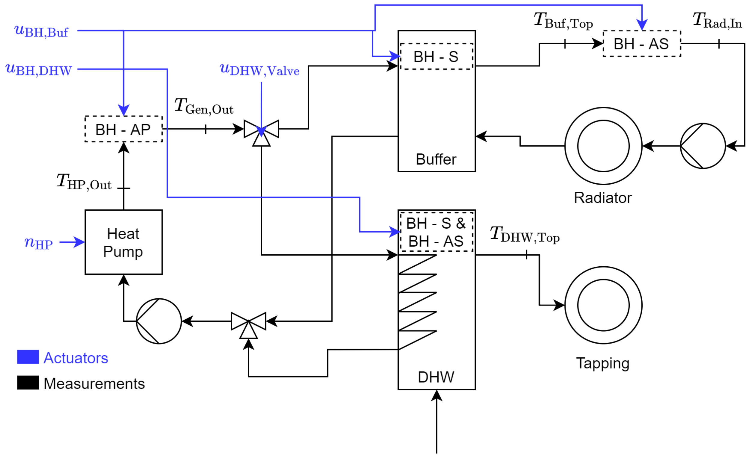
2.2. Where to Place?

Section 1 highlights three common placements for BH integration: After heat pump, inside/parallel to the storage, and after storage. Figure 1 depicts the energy system structure and the three placements. Even though a gas-fired BH is not considered for the placement after heat pump in the literature or an electric BH is not assessed for the placement after storage, we study all possible combinations of type and placement.
The heat pump’s temperature levels are key for efficiency. As we expect the storage temperature levels to be similar for the options inside and parallel to the storage, we neglect the option parallel to the storage and just calculate the option inside the storage. For gas-fired BH, parallel integration implies one device for space heating and DHW. Thus, the combination gas-fired BH inside the storage is not realistic. Nevertheless, we calculate and discuss this combination.
Regardless of the chosen type and placement, the resulting bivalent heat pump system needs an operating strategy.

2.3. How to Control?
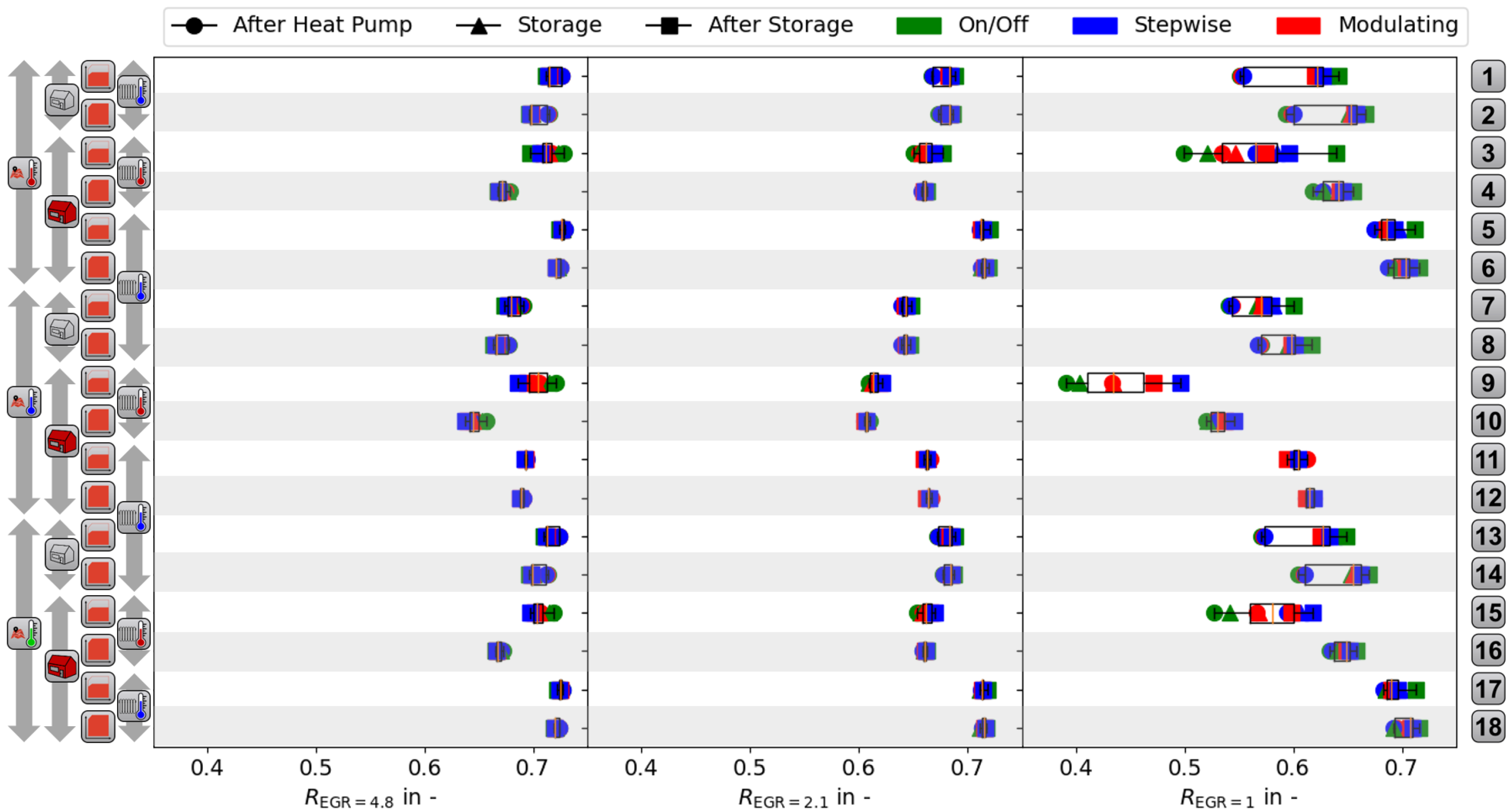
For all cases, the heat pump, at least one BH, the pumps, and the three-way valve are controlled based on actuator values. Local controllers translate set points and the control logic to actuator signals. For both the building and DHW demand, a hysteresis and timer decide whether the heat pump or BH should be activated following [15,35]. DHW is assigned a higher priority as in [15]. If the device is activated, it receives its set and measured value to calculate the actuator signal. Figure 2 illustrates the control system. Additionally, Table 1 specifies which device uses which set points and measurements from the system. Herein, it is vital to set the DHW set point onto the upper hysteresis limit to ensure a fast DHW charging and prevent thermal discomfort in the building.
We want to highlight two control blocks:
First, the operational envelope control ensures that the operational limits are not violated. If the set temperature exceeds the maximal allowed temperature T HP , Max , the set temperature for the heat pump is equal to T HP , Max , and the BH is activated. The operational envelope gives the maximal value T OE . A constant dead band Δ T OE is employed to avoid upper limit violations in transient operation. This sort of control is requested by [13] but is not publically available.
Second, the control block in use depends on the modulating capacity of the BH:
  • On/Off: Constant hysteresis with 10 K bandwidth;
  • Stepwise: Stepwise hysteresis. For stage one, 2 K bandwidth is applied. For stage two, 4 K bandwidth, etc.;
  • Modulating: PI control with a proportional gain of 0.2 and integral gain of 1000 s . The same values apply to the heat pump controller.
As examined in Section 1, the application scenario may influence the optimal type, placement, and control.

2.4. Study Design

To analyze all interactions between the three questions for different scenarios, we apply a full-factorial experimental plan as the study design [38]. The factors and levels of the study are based on the case of a homeowner of a non-refurbished building who wants to install a heat pump system. Given that case, investment options regarding the building envelope, heat transfer system, and heat pump system arise.
As the homeowner may live anywhere, we evaluate varying weather conditions.

2.4.1. Building Envelope

Typically, non-refurbished buildings face high heat demand. Retrofitting the building is the first option to reduce demand and make the heat pump a viable but capital-intensive option. Thus, we consider a non-refurbished and refurbished case as levels for the building envelope factor. For the building model, we use one representative model for Germany according to [39] and the modeling approach from [40].

2.4.2. Heat Transfer System

In addition to high heat demands, non-refurbished buildings are typically equipped with radiators facing high temperature demands, i.e., 75/65 C . If a refurbishment is realized, the required temperatures of the old radiators decrease [4]. If no refurbishment is applied, increasing radiators’ quality or size will reduce temperature demand. While both cases drastically increase heat pump efficiency, an investment is required. Thus, we consider two nominal temperature level cases for non-refurbished buildings: 75/65  C and 55/45  C for flow and return temperatures, respectively. For refurbished buildings, one level is analyzed: 55/45  C . Note that these are the nominal values at nominal outdoor air temperatures. At higher outdoor air temperatures, the temperature demand decreases [4].

2.4.3. Heat Pump System

In addition to the radiators and the building envelope, a homeowner can choose between different heat pump system setup options. Most essential to meet a high temperature demand is the operational envelope. In the current market, heat pumps with low upper temperature limits, e.g., 60 C , and high upper temperature limits, e.g., 70 C , exist [10,11]. As levels for the factor heat pump, we study low and high operational envelopes.

2.4.4. Weather Conditions

Last, as stated in Table 1 and Figure 3, the outdoor air temperatures influence the type, placement and control due to varying design, efficiencies, or operational envelope violations. As retrofit heat pump systems are essential for multiple locations, we study three climate zones from Germany. Cold, average, and warm zones are considered as levels according to Germany’s National Meteorological Service [41] to analyze the worst (Fichtelberg), best (Mannheim), and average (Potsdam) case of weather.
The resulting temperature demands are depicted in Figure 3. The first demand, DHW, has a constant temperature set point. The second demand, the building, depends on the location and the radiator design. The location specifies the nominal outdoor air temperatures T Oda , Nom . At these temperatures, radiators are designed for nominal supply temperatures T Rad , Nom . For instance, radiators are designed to meet the heat demand of a building in Fichtelberg (F) at T Oda , Nom , F of 14.4   C and T Rad , Nom of 75 C . Each red cross depicted indicates a considered combination of T Oda , Nom and T Rad , Nom . For higher and lower T Oda , the supply temperature T Rad , Sup increases or decreases. The probability of each considered weather location is given in the upper part.
The BH may be used in two cases. First, the temperature demand exceeds the operational envelope, which is an upper limit for the heat pump. To avoid frequent violation of the operational envelope, we use a safety temperature difference Δ T OE of 5 K . Second, the heat demand at T Oda < T Biv may exceed the heat pump capacity, resulting in the necessity of the BH.
For each listed combination, the placement and control of the BH are further factors, with three levels each. Hence, 162 combinations arise. For each, we conduct an annual simulation. For better visualization, Figure 4 marks all scenario options using icons.

2.4.5. System Design

Section 1 examines bivalent design to reduce capital cost. As gas boilers and electrical heating rods are viable options for retrofit, bivalent part-parallel design is applied. In this design, the BHs design depends on the nominal demand of the building Q ˙ Bui , Nom and the DHW Q ˙ DHW , Nom . The former is calculated using [42], the latter using the critical period in [9]. Depending on the placement of the BH, different designs are applied:
  • After Heat Pump: Q ˙ BH = Q ˙ Bui , Nom + Q ˙ DHW , Nom ;
  • Storage and after Storage: Q ˙ BH , Bui = Q ˙ Bui , Nom , and Q ˙ BH , DHW = Q ˙ DHW , Nom .
Values of Q ˙ Bui , Nom for all cases are listed in Table A1. For DHW, all studies use Profile M according to [43]. Thus, Q ˙ DHW , Nom is equal to 868 W .
In addition to BH, the heat pump needs to be sized. Finding optimal design sizes for each scenario is possible, following [14,15], but also computationally expensive. Finding 162 optimal designs for each case would exceed the scope of this contribution. Thus, as no clear guide for the choice of heat pump size exists, we use the bivalence temperature 2   C , as suggested by [17]. Future studies should investigate the influence of the bivalence temperature on the type, placement, and control of the BH.

2.4.6. System Model

To account for detailed physics and dynamics, we model the system using Modelica. Our models are based on the open-source available Modelica libraries AixLib [44] and BESMod [45]. For the heat pump model, the performance data approach based on the VCLib [46] presented in [15] applies. The open-source repository accompanying this contribution (https://github.com/RWTH-EBC/BackupHeaterIntegration, accessed on 8 August 2022) documents control models not given in the AixLib or BESMod, model parameters, and the overall system model. For solving the system model, Dassl is used with a variable step size of 15 min [47].
The following section presents the results of this study.

3. Results

As vital tools of a sustainable building energy sector, heat pump systems require low costs and emissions and supply a high thermal comfort. Thus, we analyze the results regarding these three metrics.

3.1. Costs and Emissions

As the final energy consumption (FEC) primarily influences costs and emissions, we first analyze the FEC of the combinations. To understand differences in FEC, we further analyze the heat pump’s S C O P HP , the number of operational envelope violations N OE , HP , and the share of BH usage α BH . Figure 5 illustrates this analysis.
Depending on the scenario, savings in the FEC compared to the median FEC consumption over all nine combinations of control and placement reaches up to 18%. Comparing the best to the worst case, the choice of placement and control enables savings in FEC of up to 30%. These savings result primarily from the case of a low operational envelope and a high temperature demand applied in cold weather. This case can be considered the worst-case application for a heat pump. Nevertheless, such system configurations may be necessary for an all-electric building sector.
Looking at the other scenarios, savings compared to the median decision range up to 9.3%. Thus, the correct choice of BH placement and control is important for all retrofit heat pump applications. As the S C O P HP does not vary much, the savings are attributed to the lower BH usage α BH for the cases after the storage. The integration inside the storage is mostly close to the median.
The placement after the heat pump performs worse than the others, especially for refurbished buildings. This effect results from the high share of DHW in refurbished buildings and the increased usage of the BH for DHW demand. While all placements need the BH to supply DHW in cases of a low operational envelope, the cases inside and after the storage use a smaller BH for DHW. Thus, charging takes longer compared to the single oversized BH. Longer charging enables prolonged heat pump operation and thus a lower share of the BH.
Going into detail on why the placement influences the FEC and thus costs and emissions, Figure 6 displays and analyzes the time series for a winter day.
On the left side, the high temperature demand T Set results from low outdoor air temperatures. As the set point is higher than the maximal heat pump temperature, the BH is activated in all cases. However, the BH after the heat pump results in high heat pump inlet temperatures, leading to violations of the operational envelope N ERR , visible on the right side. Therefore, the BH dominates the electricity demand W el . Moreover, switching the heat pump is prohibited, as the inlet temperature exceeds the operational envelope. Figure 5 depicts this. The options after the heat pump show the lowest operational envelope violations.
For the BH in the storage, the heat pump inlet temperatures increase if the heat pump turns on, as the storage itself is on a high temperature level. Thus, frequent operational envelope violations and heat pump switches occur. Again, F E C BH dominates F E C HP . Overall, BHs inside the storage lead to a higher number of operational envelope violations, with up to 2000 violations (cf. Figure 5). If the heat pump turns on, the upper storage temperature decreases, leading to low control quality in the upper storage layer.
Last, the placement after the storage decouples the low temperature heat pump supply and the high temperature demand. Only one violation occurs when switching to the DHW storage. Afterward, the heat pump can operate inside the operational envelope. While F E C BH still dominates F E C HP , the overall energy demand decreases. Compared to the results for the case in the storage, the heat pump inlet temperature is not significantly lower. However, as the storage is colder, the heat pump inlet temperatures do not rise that fast, and the heat pump can still provide a small temperature difference at minimal compressor frequency.
For electric heating rods as BH, the FEC is equal to the electricity demand and, thus, proportional to costs. For gas-fired BHs, the electricity-to-gas ratio for costs and emissions is relevant. Thus, we apply Equations (8) and (9) and investigate costs and emissions for different EGR and BH types. The values for EGR are representative for 2021 in Germany. Figure 7 displays the costs and emissions reductions R for these three EGR.
Here, an increased gas-fired BH usage is economically beneficial, assuming EGR values for Germany in 2021. Compared to an ideal heater, between 60% and 75% cost reductions are achieved. A slightly lower range is valid if the EGR shrinks to 2.1. For equal costs of electricity and gas, the possible reductions range between 40% and 75%. Thus, with an EGR of 1, the choice of placement and control of the BH is important, making it always crucial for an electric heating rod as BH. For a gas-fired BH with higher EGR, the choice is less critical.
Regarding optimal placement and control, the positive effect of less BH usage of the heating rod case (EGR = 1) is damped when using a gas-fired BH. Assuming an EGR of 2.1, costs and emissions are lower for positions after and inside the storage due to the separate DHW BH. For an EGR of 4.8, the placements after the heat pump are even better, as the cost reduction is always the highest.
In addition to costs and emissions, thermal comfort has to be met.

3.2. Thermal Comfort

While the costs and emissions vary depending on the BH’s type, placement, and control, the system’s thermal comfort is given in most cases. Figure A3 displays the comfort for all cases next to the absolute FEC reductions. As thermal comfort is calculated following [48], values below 73 Kh are rated as comfortable.
Figure 8 depicts all cases violating this boundary condition.
Two reasons lead to the described comfort violations:
First, for the cold weather conditions, the minimum outdoor air temperature is 17.1   C , while the nominal outdoor air temperature is 14.4   C . Thus, the normative system design yields discomfort. Despite that, modulating and stepwise BH after the heat pump or after the storage enable high comfort.
Second, on/off controlled BH yield generally lower comfort, especially for the placement after the storage, due to limited inertia of the heating system. As soon as the BH achieves its hysteresis limit, it turns off, leading to colder storage water flowing into the radiators. While the BH is activated repeatedly, these colder storage temperatures yield discomfort. The control could be adapted to avoid discomfort with on/off devices after the storage. However, the BH would frequently switch on and off, leading to fatigue. Thus, as presented in current guidelines [12,13] and stated in Section 2, on/off devices after the storage are not preferable.
In addition to on/off control, BH may be operated fully modulating or in a stepwise manner. In here, the results show a trade-off between control accuracy and efficiency. Figure 9 displays this trade-off for scenarios 16 and 17. While modulating devices after or in the storage achieve the highest comfort levels down to 12 Kh, FEC consumption increases up to 10% compared to stepwise devices due to more BH usage. At the same time, a maximal decline of 7 Kh in comfort for stepwise controlled devices is calculated.
After analyzing the results using costs, emissions, and thermal comfort, we discuss limitations and implications in the following section.

4. Discussion

The results show that the type, placement, and control are essential factors when integrating a BH into a retrofit heat pump system. At the same time, this contribution shows methodological and practical limitations, which need consideration when discussing the implications for research and practice of the three questions: Which to choose, where to place, and how to control?

4.1. Which to Choose?

Two types of BH are relevant: Gas-fired and electric BH.

4.1.1. Methodological Limitations

This contribution is not designed to answer the question of which to choose for all cases, as EGR predictions are inherently uncertain for costs and emissions, and heat pump systems are expected to operate for more than ten years. Following Equations (8) and (9), displayed in Figure 7, the results are valid for any EGR.
For a high EGR, the placement after the heat pump reduces costs more than other placements. However, the control minimizes the BH usage and does not consider the current EGR. Thus, similar reductions would also be possible for the other considered placements.
Further, while the ideal heater model serves as a reasonable basis for this analysis, future studies should validate the findings by modeling gas-fired devices in more detail, such as in [22].

4.1.2. Practical Limitations

In practice, existing gas-fired BHs may not be able to communicate with the heat pump or a central control. The control method in this contribution assumes such interactions. Thus, future studies should incorporate the case of separate control of gas-fired BH and heat pump.

4.1.3. Implications

The applied rule-based local control in this contribution is designed to minimize the BH usage following normative recommendations. Various contributions present supervisory control methods such as MPC [28,29,30]. These methods can achieve economically or ecologically optimal control strategies which decide whether to use the BH or the heat pump depending on the EGR. For instance, if the homeowner uses renewable PV, an EGR of nearly zero would apply. Then, gas-fired BH usage should be minimal if PV electricity is generated. At the same time, if the EGR in a country rises above the S C O P of the heat pump, gas-fired BH can reduce costs.
Thus, regardless of the EGR scenario, it is important that:
  • A supervisory control can activate either heat pump or gas-fired BH, depending on the current EGR.
  • A local control and a correct placement enable the minimal usage of the BH for times of low EGR.
Without a correct placement and local control, users of hybrid systems could face both high costs and emissions.

4.2. Where to Place?

The results indicate that an integration after the storage is favorable in most scenarios. However, three limitations are discussed.

4.2.1. Methodological Limitations

A first limitation lies in consideration of the options parallel to storage and inside the storage as equal options. Motivated by the same implications for the heat pump temperature levels, future studies must check this simplification. For instance, BHs parallel to the storage requires a pump, increasing the electricity demand, which is not accounted for in this study. Furthermore, parallelly integrated BHs could face the same issue as BHs after the heat pump, charging the DHW storage faster compared to using a separate, smaller device.

4.2.2. Practical Limitations

Second, demand-side management with a potential electric BH is inhibited after the storage. As the BH for DHW is integrated inside the storage, some demand flexibility is exploitable. However, as DHW storage has a limited size, integrating the BH after storage could limit the flexibility potential of the energy system. However, the heat pump could still provide flexibility. At the same time, for the retrofit studies, integration inside the buffer storage is economically similar to the integration after the storage. Thus, if demand-side management using an electric heating rod is essential for the user, the BH inside the storage should be preferred. However, following [30], the heat pump should be used in any case. Third, installing a BH after the storage needs additional discussion. In practice, heat pumps are often equipped with the heating rod in series, with both devices mounted together. Separating their placement, commissioners could face higher installation times. However, manufacturers choose serial integration based on the guidelines in [9,13]. Thus, they should adjust their product to facilitate a fast installation process.

4.2.3. Implications

For a high temperature demand, the results indicate that a BH integration after the storage is favorable. [12,13] suggest this option, however, only for gas-fired BHs. For electric heating rods, an installation after the heat pump or inside the storage is recommended. The placement is less crucial if low temperatures are required and the heat pump can achieve high temperatures. However, the placement after the storage still outperforms with regard to FEC savings. Thus, the placement after the storage should be suggested as a standard option for practitioners.

4.3. How to Control?

In addition to type and placement, the control question (on/off, stepwise, or modulating) is addressed.

4.3.1. Methodological Limitations

In developing the presented control strategy, several options for set and measured values are considered. However, all options yield a less efficient system. While the given strategy is not optimal, as advanced MPC approaches, its applicability over several weather conditions, building envelopes, operational envelopes, and radiators demonstrates its broad applicability.
In the current version, a control drawback results for the placement after the heat pump. Herein, the DHW tank is charged faster than in the other cases, leading to lower heat pump usage. At the same time, the DHW temperatures, or the comfort levels, stay the same. As the BH is sized for DHW and space heating, it is vastly oversized for DHW alone. For on/off and stepwise devices, as common for the placement after the heat pump, a better control strategy is challenging to realize. However, for modulating BH, a separate set of PI parameters could dampen this effect. At the same time, these parameters would need close attention in practice, as user comfort may be reduced if DHW charging takes too long.
The same limitation would result for the placement parallel to the storage if only one BH is used, such as the gas-fired BH in [12,13].

4.3.2. Practical Limitations

Regarding the control options on/off, stepwise, and modulating, trade-offs between costs, emissions, and comfort need consideration. On/off devices result in discomfort for non-refurbished buildings and the placement after the storage. Current guidelines are aware of this drawback, suggesting a parallel integration for on/off devices.

4.3.3. Implications

In addition to the discussed limitations, fully modulating devices do not improve efficiency or comfort compared to discrete devices with five steps. Thus, for the placements inside the storage and after the heat pump, stepwise BH are sufficient for the considered scenarios. However, if a stepwise device contains fewer than five steps, modulating devices should be selected for the placement after the storage.
In addition to the question-specific implications, two overarching implications for research arise.
First, the building envelope and weather data scenarios focus on Germany. Including other countries with different boundary conditions is promising to investigate the transferability of results. Second, the findings of these annual simulations should be validated in dedicated experiments to assess modeling uncertainties.

5. Conclusions

This paper analyzes the integration of back-up heaters in retrofit heat pump systems by answering the questions: Which to choose?, Where to place?, and How to control? Analyzing relevant options and scenarios using detailed annual simulations using Modelica, we found several implications for future research and practice:
  • In times of uncertain electricity-to-gas ratios for costs and emissions, currently developed heat pump systems should always enable a minimal usage of the back-up device through correct placement and control. For gas-fired back-up devices, supervisory control based on model predictive control methods as reviewed by [28] should be deployed.
  • Towards such minimal usage, the placement is vital. Against recommendations by current guidelines [9,12] for electric heating rods, the back-up heater should always be placed after the storage or at least in parallel to the storage. For gas-fired back-up heaters, current recommendations are in line with the findings of [12,13].
  • We analyze a broad set of retrofit options. Extending the set of boundary conditions (building, radiators, weather) should follow as a next step, for instance for new buildings, underfloor heating, or additional countries representing different climate zones.
  • The type, placement, and control of the back-up heater interact. The same applies to the heat pump design, as shown by current research [14,15]. Combining the optimal back-up heater integration into the optimal heat pump design is a promising research prospect to exploit the potential to decarbonize the building sector with heat pump systems.

Author Contributions

F.W.: Conceptualization, methodology, software, investigation, resources, data curation, writing—original draft preparation, writing—review, visualization; C.V.: writing—original draft preparation, writing—review and editing, visualization; L.M.: review and editing, visualization; D.M.: supervision, project administration, funding acquisition, writing—review and editing. All authors have read and agreed to the published version of the manuscript.

Funding

This research was funded by the Federal Ministry for Economic Affairs and Climate Action (BMWK) promotional reference 03EN1022B.

Data Availability Statement

The data presented in this study are openly available in https://github.com/RWTH-EBC/BackupHeaterIntegration, accessed on 8 August 2022.

Acknowledgments

We gratefully acknowledge the financial support by the Federal Ministry for Economic Affairs and Climate Action (BMWK), promotional reference 03EN1022B. This work was supported by the European Regional Development Fund (ERDF) (EFRE-0500029).

Conflicts of Interest

The authors declare no conflict of interest.

Abbreviations

The following abbreviations are used in this manuscript:
APAfter Heat Pump
ASAfter Storage
α Usage ratio
BHBack-up heater
BuiBuilding
ccosts
CCosts
C O P Coefficient of Performance
DemDemand
DHWDomestic Hot Water
eemissions
EEmissions
EGRElectricity-to-Gas ratio
elElectricity
η Efficiency
ffactor
FECFinal Energy Consumption
FichtelbergF
GenGeneration
HPHeat Pump
HPSHeat Pump System
HysHysteresis
LoaLoading
MannheimM
MeaMeasurements
MPCModel Predictive Control
OEOperational Envelope
PotsdamP
PhotovoltaicsPV
QHeat flow rate
RReduction
RadRadiator
RBCRule-based Control
SStorage
S C O P Seasonal Coefficient of Performance
TotTotal
W el Electricity Demand

Appendix A

This appendix section lists method details possibly relevant for understanding the result and discussion of the contribution.
Table A1. Nominal heat demands and temperatures for the two buildings and three locations of the analysis.
Location T Oda , Nom in CNon-Refurbished Q ˙ Bui , Nom in kWRefurbished Q ˙ Bui , Nom in kW
Potsdam−12.116.35.6
Fichtelberg−14.417.46.0
Mannheim−10.515.55.3

Appendix B

Detailed results of all 162 simulations are stated in this section.
Figure A1. Boxplots for all conducted studies regarding saving potential, heat pump on/off switches, and backup-heater usage.
Energies 15 07134 g0a1
Figure A2. Boxplots for all conducted studies regarding costs and emissions reduction R for different EGR.
Energies 15 07134 g0a2
Figure A3. Boxplots for all conducted studies regarding saving potential and thermal comfort.
Energies 15 07134 g0a3

References

  1. RHEVA—Federation of European Heating, Ventilation and Air Conditioning Associations. Heat Pumps Are Key to Decarbonizing Residential Heating. 2022. Available online: https://www.rehva.eu/rehva-journal/chapter/heat-pumps-are-key-to-decarbonizing-residential-heating (accessed on 2 August 2022).
  2. Bundesamt, S. More than Half of the Residential Buildings Constructed in 2021 Are Heated by Heat Pumps. 2022. Available online: https://www.destatis.de/DE/Presse/Pressemitteilungen/2022/06/PD22_226_31121.html (accessed on 2 August 2022).
  3. Bundesverband der Deutschen Heizungsindustrie. Gesamtbestand Zentrale Wärmeerzeuger 2021. 2022. Available online: https://www.bdh-industrie.de/fileadmin/user_upload/Pressegrafiken/Diagramm_Gesamtzahl_Waermeerzeuger_2021_DE.pdf (accessed on 5 August 2022).
  4. Lämmle, M.; Bongs, C.; Wapler, J.; Günther, D.; Hess, S.; Kropp, M.; Herkel, S. Performance of air and ground source heat pumps retrofitted to radiator heating systems and measures to reduce space heating temperatures in existing buildings. Energy 2022, 242, 122952. [Google Scholar] [CrossRef]
  5. Keinath, C.M.; Garimella, S. An energy and cost comparison of residential water heating technologies. Energy 2017, 128, 626–633. [Google Scholar] [CrossRef]
  6. Bundesverband Wärmepumpe e.V. BWP-Branchenstudie 2015. 2015. Available online: https://www.waermepumpe.de/fileadmin/user_upload/waermepumpe/07_Publikationen/2016-04-08_Branchenprognose_2015_web.pdf (accessed on 4 August 2022). (In German).
  7. Recknagel, H.; Albers, K.J.; Sprenger, E. (Eds.) Taschenbuch für Heizung und Klimatechnik: Einschließlich Trinkwasser- und Kältetechnik Sowie Energiekonzepte. Band 2; 79th edition, 2019/2020 ed.; Recknagel Edition; ITM InnoTech Medien GmbH: Augsburg, Germany, 2018. [Google Scholar]
  8. Van Kenhove, E. Coupled Thermohydraulic and Biologic Modelling of Legionella Pneumophila Proliferation in Domestic Hot Water Systems. Ph.D. Thesis, Universität Gent, Ghent, Belgium, 2018. Available online: https://biblio.ugent.be/publication/8587971/file/8587972.pdf (accessed on 5 August 2022).
  9. German Institute for Standardization. EN 15450 Heating Systems in Buildings—Design of Heat Pump Heating Systems; German Version EN 15450:2007; Technical Report; Beuth Verlag GmbH: Berlin, Germany, 2007. [Google Scholar]
  10. Viessmann. Vitocal 200-A Technical Guide. 2022. Available online: https://www.haustechnik-handrich.de/media/pdf/a1/75/65/vie-pa-z015192.pdf (accessed on 4 July 2022).
  11. Viessmann. Vitocal 250-A Technical Guide. 2022. Available online: https://www.haustechnik-handrich.de/media/pdf/54/c4/14/vie-pa-z022164.pdf (accessed on 4 July 2022).
  12. Bundesverband Wärmepumpe e.V. Leitfaden Hydraulik. 2016. Available online: https://www.waermepumpe.de/uploads/media/BWP_LF_Hydraulik_final_web.pdf (accessed on 2 September 2022). (In German).
  13. Bundesindustrieverband Deutschald Haus, Energie, u.U.e. Bivalente Wärmepumpen-Systeme. 2014. Available online: https://www.bdh-industrie.de/fileadmin/user_upload/Publikationen/Infoblaetter/Infoblatt_Nr_57_Bivalente_Waermepumpensysteme.pdf (accessed on 5 August 2022). (In German).
  14. Dongellini, M.; Naldi, C.; Morini, G.L. Influence of sizing strategy and control rules on the energy saving potential of heat pump hybrid systems in a residential building. Energy Convers. Manag. 2021, 235, 114022. [Google Scholar] [CrossRef]
  15. Vering, C.; Wüllhorst, F.; Mehrfeld, P.; Müller, D. Towards an integrated design of heat pump systems: Application of process intensification using two-stage optimization. Energy Convers. Manag. 2021, 250, 114888. [Google Scholar] [CrossRef]
  16. Bagarella, G.; Lazzarin, R.; Noro, M. Annual simulation, energy and economic analysis of hybrid heat pump systems for residential buildings. Appl. Therm. Eng. 2016, 99, 485–494. [Google Scholar] [CrossRef]
  17. German Institute for Standardization. DIN V 4701-10. Energy Efficiency of Heating and Ventilation Systems in Buildings-Part 10: Heating, Domestic Hot Water Supply, Ventilation; German Version 4701-10:2003; Technical Report; Beuth Verlag GmbH: Berlin, Germany, 2003. [Google Scholar]
  18. CEN Keymark. Heat Pump KEYMARK Certificates. 2022. Available online: https://keymark.eu/en/products/heatpumps/certified-products (accessed on 5 August 2022).
  19. Umweltbundesamt. CO2-Emissionsfaktoren für Fossile Brennstoffe. September 2016. Available online: https://www.umweltbundesamt.de/sites/default/files/medien/1968/publikationen/co2-emissionsfaktoren_fur_fossile_brennstoffe_korrektur.pdf (accessed on 2 August 2022). (In German).
  20. Umweltbundesamt. CO2-Emissionen Pro Kilowattstunde Strom Steigen 2021 Wieder an. 2022. Available online: https://www.umweltbundesamt.de/themen/co2-emissionen-pro-kilowattstunde-strom-steigen (accessed on 2 August 2022). (In German).
  21. Bundesamt, S. Erdgas- und Stromdurchschnittspreise. 2022. Available online: https://www.destatis.de/DE/Themen/Wirtschaft/Preise/Erdgas-Strom-DurchschnittsPreise/_inhalt.html (accessed on 2 August 2022).
  22. Simic, K.; T’Jollyn, I.; Faes, W.; Borrajo Bastero, J.; Laverge, J.; De Paepe, M. Modelling of a gas-fired heating boiler unit for residential buildings based on publicly available test data. Energy Build. 2021, 253, 111451. [Google Scholar] [CrossRef]
  23. European Comission. 2030 Climate Target Plan. Available online: https://ec.europa.eu/clima/eu-action/european-green-deal/2030-climate-target-plan_en (accessed on 5 August 2022).
  24. Bagarella, G.; Lazzarin, R.; Noro, M. Sizing strategy of on–off and modulating heat pump systems based on annual energy analysis. Int. J. Refrig. 2016, 65, 183–193. [Google Scholar] [CrossRef]
  25. Vering, C.; Maier, L.; Breuer, K.; Krützfeldt, H.; Streblow, R.; Müller, D. Evaluating heat pump system design methods towards a sustainable heat supply in residential buildings. Appl. Energy 2022, 308, 118204. [Google Scholar] [CrossRef]
  26. Di Perna, C.; Magri, G.; Giuliani, G.; Serenelli, G. Experimental assessment and dynamic analysis of a hybrid generator composed of an air source heat pump coupled with a condensing gas boiler in a residential building. Appl. Therm. Eng. 2015, 76, 86–97. [Google Scholar] [CrossRef]
  27. Floss, A.; Hofmann, S. Optimized integration of storage tanks in heat pump systems and adapted control strategies. Energy Build. 2015, 100, 10–15. [Google Scholar] [CrossRef]
  28. Drgoňa, J.; Arroyo, J.; Cupeiro Figueroa, I.; Blum, D.; Arendt, K.; Kim, D.; Ollé, E.P.; Oravec, J.; Wetter, M.; Vrabie, D.L.; et al. All you need to know about model predictive control for buildings. Annu. Rev. Control. 2020, 50, 190–232. [Google Scholar] [CrossRef]
  29. D’Ettorre, F.; Conti, P.; Schito, E.; Testi, D. Model predictive control of a hybrid heat pump system and impact of the prediction horizon on cost-saving potential and optimal storage capacity. Appl. Therm. Eng. 2019, 148, 524–535. [Google Scholar] [CrossRef]
  30. Salpakari, J.; Lund, P. Optimal and rule-based control strategies for energy flexibility in buildings with PV. Appl. Energy 2016, 161, 425–436. [Google Scholar] [CrossRef]
  31. Killian, M.; Kozek, M. Ten questions concerning model predictive control for energy efficient buildings. Build. Environ. 2016, 105, 403–412. [Google Scholar] [CrossRef]
  32. Sturzenegger, D.; Gyalistras, D.; Morari, M.; Smith, R.S. Model Predictive Climate Control of a Swiss Office Building: Implementation, Results, and Cost–Benefit Analysis. IEEE Trans. Control. Syst. Technol. 2016, 24, 1–12. [Google Scholar] [CrossRef]
  33. Afram, A.; Janabi-Sharifi, F. Theory and applications of HVAC control systems—A review of model predictive control (MPC). Build. Environ. 2014, 72, 343–355. [Google Scholar] [CrossRef]
  34. Clauß, J.; Georges, L. Model complexity of heat pump systems to investigate the building energy flexibility and guidelines for model implementation. Appl. Energy 2019, 255, 113847. [Google Scholar] [CrossRef]
  35. Madani, H.; Claesson, J.; Lundqvist, P. A descriptive and comparative analysis of three common control techniques for an on/off controlled Ground Source Heat Pump (GSHP) system. Energy Build. 2013, 65, 1–9. [Google Scholar] [CrossRef]
  36. Fischer, D.; Wolf, T.; Wapler, J.; Hollinger, R.; Madani, H. Model-based flexibility assessment of a residential heat pump pool. Energy 2017, 118, 853–864. [Google Scholar] [CrossRef]
  37. Roccatello, E.; Prada, A.; Baggio, P.; Baratieri, M. Analysis of the Influence of Control Strategy and Heating Loads on the Performance of Hybrid Heat Pump Systems for Residential Buildings. Energies 2022, 15, 732. [Google Scholar] [CrossRef]
  38. Antony, J. Design of Experiments for Engineers and Scientists, 2nd ed.; Elsevier Insights; Elsevier: London, UK, 2014. [Google Scholar]
  39. Vering, C.; Otto, A.; Mortimer, M.; Mehrfeld, P.; Müller, D. ACoolHeaD: Framework for Automated Cooling and Heating Demand calculations using spatially and temporally resolved building performance simulations applied to the estimation of heating demand in Germany. Energy Build. 2021, 252, 111442. [Google Scholar] [CrossRef]
  40. Remmen, P.; Lauster, M.; Mans, M.; Fuchs, M.; Osterhage, T.; Müller, D. TEASER: An open tool for urban energy modelling of building stocks. J. Build. Perform. Simul. 2018, 11, 84–98. [Google Scholar] [CrossRef]
  41. Germany’s National Meteorological Service. Test Reference Yeas (TRY). 2017. Available online: http://www.dwd.de/DE/leistungen/testreferenzjahre/testreferenzjahre.html (accessed on 5 August 2022).
  42. German Institute for Standardization. Energy Performance of Buildings—Method for Calculation of the Design Heat Load; German Version EN 12831:2017; Technical Report; Beuth Verlag GmbH: Berlin, Germany, 2017. [Google Scholar]
  43. Union, E. Commission Delegated Regulation (EU) No 811/2013. 2013. Available online: https://eur-lex.europa.eu/eli/reg_del/2013/811/oj (accessed on 5 August 2022).
  44. Müller, D.; Lauster, M.; Constantin, A.; Fuchs, M.; Remmen, P. AixLib—An Open-Source Modelica Library within the IEA-EBC Annex 60 Framework; BauSIM 2016; RWTH Aachen University: Aachen, Germany, 2016; Available online: http://www.iea-annex60.org/downloads/2016-bausim-aixlib.pdf (accessed on 1 July 2022).
  45. Wüllhorst, F.; Maier, L.; Jansen, D.; Hering, D. BESMod—A Modelica Library providing Building Energy System Modules. In Proceedings of the American Modelica Conference, Dallas, TX, USA, 22–28 October 2022; Available online: https://github.com/RWTH-EBC/BESMod (accessed on 5 August 2022).
  46. Vering, C.; Engelpracht, M.; Göbel, S.; Hoseinpoori, S.; Wüllhorst, F.; Schwenzer, C.; Rademacher, M.; Hinrichs, S.; Chandra, F.; Mehrfeld, P.; et al. Open-Source vapor compression library (VCLib): Heat pump modeling for education and research. Comput. Appl. Eng. Educ. 2022, 30, 1498–1509. [Google Scholar] [CrossRef]
  47. Petzold, L.R. Description of DASSL: A Differential/Algebraic System Solver; Technical Report; Sandia National Laboratorias: Livermore, CA, USA, 1982. [Google Scholar]
  48. German Institute for Standardization. DIN EN 16798-1. Indoor Environmental Input Parameters for Design and Assessment of Energy Performance of Buildings Addressing Indoor Air Quality, Thermal Environment, Lighting and Acoustics; German Version EN 16798-1:2019; Technical Report; Beuth Verlag GmbH: Berlin, Germany, 2022. [Google Scholar]
Figure 1. Three possible placements for BHs in parallel storage configuration according to [9,12,13]. After heat pump (BH-AP), inside the buffer storage (BH-S), and after the buffer storage (BH-AS). For the latter two, the BH is located in the DHW storage. Furthermore, control-relevant measurements points are stated.
Energies 15 07134 g001
Figure 2. This rule-based control logic ensures that the system meets the building and DHW demands.
Energies 15 07134 g002
Figure 3. The temperature demands of all case studies are depicted in the lower part. The histogram curves of the outdoor air temperature probabilities p are depicted in the upper part for the three locations: Fichtelberg (F), Potsdam (P), and Mannheim (M). Further, the nominal outdoor air temperature is indicated in the lower part.
Energies 15 07134 g003
Figure 4. The simulation study considers different combinations of weather, building, radiator, and operational envelope.
Energies 15 07134 g004
Figure 5. Boxplots of the FEC, the heat pump efficiency, S C O P HP , the BH usage α BH , and the number of times the operational envelope is violated for a selected set of scenarios. See Figure A1 for all scenarios.
Energies 15 07134 g005
Figure 6. Comparison of the temperature curves for BH placements in non-refurbished buildings, warm weather with high supply temperatures and low operational envelope (Scenario 3).
Energies 15 07134 g006
Figure 7. Boxplots of the reduction R in costs and emissions with different EGR for a selected set of scenarios. See Figure A2 for all scenarios.
Energies 15 07134 g007
Figure 8. F E C saving potential and thermal comfort Δ T Comfort for a selected set of scenarios. The On/Off BH after the storage yields discomfort in several cases. Furthermore, a non-refurbished building equipped with low temperature heating in cold weather results in discomfort in most scenarios. Refurbishment leads to higher comfort even for a low operational envelope. See Figure A3 for all scenarios.
Energies 15 07134 g008
Figure 9. Thermal discomfort according to [48] versus electricity demand. For both cases, average weather and a non-refurbished building apply. (a) Scenario 16: High operational envelope and radiators with 75  C nominal temperature demand. (b) Scenario 17: Low operational envelope and radiators with 55  C nominal temperature demand.
Energies 15 07134 g009
Table 1. Set and measured values for control of space heating and DHW for different placements of back-up heaters and the heat pump. Refer to Figure 1 for the measurement points of stated variables.
Device T Set , Bui T Mea , Bui T Set , DHW T Mea , DHW
BH After Heat PumpTDem,BuiTGen,OutTDem,DHW +
ΔTLoa,DHW +
ΔTHys,DHW/2
TDHW,Top
BH in StorageTDem,BuiTBuf,TopTDem,DHW +
ΔTHys,DHW/2
TDHW,Top
BH after StorageTDem,BuiTRad,InTDem,DHW +
ΔTHys,DHW/2
TDHW,Top
Heat pump min ( T HP , Max ,
T Dem , Bui )
THP,Out min ( T HP , Max ,
T Dem , DHW +
Δ T Loa , DHW +
Δ T Hys , DHW / 2 )
THP,Out
Publisher’s Note: MDPI stays neutral with regard to jurisdictional claims in published maps and institutional affiliations.

