Article

Fabrication of Graphene Sheets Using an Atmospheric Pressure Thermal Plasma Jet System

1
Department of Physics, COMSATS University Islamabad, Park Road, Islamabad 45550, Pakistan
2
Materials Laboratory, Department of Physics, COMSATS University Islamabad, Park Road, Islamabad 45550, Pakistan
3
Plasma Physics Laboratory, Department of Physics, COMSATS University Islamabad, Park Road, Islamabad 45550, Pakistan
4
Mechanical and Industrial Engineering Department, Abu Dhabi University, Abu Dhabi 111188, United Arab Emirates
5
Electrical Engineering Department, Faculty of Engineering & Technology, Future University in Egypt, New Cairo 11835, Egypt
*
Author to whom correspondence should be addressed.
Energies 2022, 15(19), 7245; https://doi.org/10.3390/en15197245
Submission received: 29 July 2022 / Revised: 14 September 2022 / Accepted: 23 September 2022 / Published: 2 October 2022
(This article belongs to the Special Issue Advances in Two-Dimensional Materials for Energy Applications)

Abstract

:
The mass production of cost-effective, large area, defect-free and high crystal quality graphene sheets with a high yield is a challenging task. In order to investigate the mechanisms involved, we report on the synthesis of graphene sheets by a homemade atmospheric pressure thermal plasma jet system, which is a single-step and less time-consuming technique. The samples were prepared by using pure Ar gas and a mixture of Ar and N2. The microstructure of the synthesized graphene sheets was characterized with the help of Raman spectroscopy, field emission scanning electron microscopy (FE-SEM) and Fourier transform infrared (FTIR) spectroscopy. The appearance of G and 2D peaks in the Raman spectrum confirmed the formation of graphene. Moreover, we observed that the addition of nitrogen increased the production of the graphene sheets but compromised the quality of those graphene sheets by increasing their structural defects. The morphology of the synthesized samples studied via FE-SEM images showed that the sheets were composed of multilayers. FTIR spectra show the presence of C=C and a hydroxyl group directly bonded to the aromatic hydrocarbon.

1. Introduction

The synthesis of atomically thick graphene layers, with extraordinary properties, has led to widespread research activities on two-dimensional crystalline materials [1]. In recent years, researchers have demonstrated the controlled fabrication of graphene related structures e.g., graphene ultra-thin sheets, nanoribbons, and carbon nanotubes. These materials have spurred the ongoing scientific research because of their intriguing features and enormous potential for practical realization in gas sensors, supercapacitors, lithium-ion batteries, transparent electrodes, solar cells, and transistors [2,3,4,5,6,7,8,9,10]. Graphene, due to its two dimensional structure, is currently known for its high mechanical strength, exceptionally good thermal conductivities as well as exotic electronic properties such as the quantum Hall effect or charge carriers acting as massless Dirac fermions [11,12]. Moreover, properties such as high charge mobility, structural stability along with mechanical and chemical strength make it a potential candidate for various technological applications in photovoltaics, shape memory, actuation, self-healing, thermoelectricity, and space missions, etc. [13]. For unveiling these properties and elucidating the role of graphene in future applications, its high yield, cost-effectiveness and controlled synthesis is highly desirable. In this regard, several methods have been used including micromechanical cleavage of graphite, thermal decomposition of silicon carbide, chemical exfoliation, chemical vapor deposition (CVD), solvothermal, plasma enhanced chemical vapor deposition (PECVD) and gas phase synthesis using microwave plasma [2,8,14,15,16,17,18,19,20,21]. The chemical exfoliation and solvothermal methods are two promising routes for the mass production of graphene but they have a disadvantage, i.e., these are chemical processes, which may induce impurities in the graphene and could also reduce its crystallinity [22,23]. On the other hand, gas-phase synthesis using microwave plasma is not a chemical synthesis route, and mass production is also possible but usually a low yield of about 1.2% is obtained [17]. CVD is one of the best methods used for the synthesis of graphene at a large scale; however, a major drawback of this technique is that it fails to produce high-quality graphene. On the other hand, the fabrication of high-quality graphene via plasma process requires appropriate conditions including the supply and controlled influx of highly energetic carbon particles to the growth zone as the presence of defects, multiple domains, wrinkles, impurities and the structural disorder affects the electronic and optical properties of the product [24].
The plasma-based synthesis of graphene is a relatively new research area with limited literature available [25,26,27,28,29,30,31,32]. The main advantage of the plasma-based synthesis technique over other existing techniques is that it can produce self-standing graphene exhibiting high quality in terms of crystalline structure. Furthermore, the chemically active plasma environment provides appropriate conditions to create unique and cost-effective pathways for producing uniform structures [7]. Thermal plasma jet is a single-step technique used for the mass production of graphene sheets without compromising its crystallinity [33]. A thermal plasma jet, at atmospheric pressure, offers suitable conditions for the synthesis of graphene, carbon nanotubes (CNTs) and graphene quantum dots (GQD) [33,34]. Graphene can be synthesized by using a jet plasma system using two different fabrication routes, either by introducing a catalyst source or by placing a plate inside the plasma plume. In 2010, Kim et al. successfully synthesized multilayer graphene structures (yield of ~8%) by employing the thermal plasma jet system [33]. Fronczak et al. reported a continuous synthesis of graphene using a thermal plasma jet, and they showed that the plasma processing of alcohols can produce graphene and carbon particles [35]. More recently, Shavelkina et al. reported on the synthesis of graphene with a DC plasma torch. They showed that the hydrogen contents in the precursor and the type of carrier gas used have a great influence on the lateral dimensions and purity of graphene [36]. Despite the previous work, a facile and scalable fabrication method that could provide a high yield of graphene using an atmospheric pressure thermal plasma jet is still needed.
Herein, we report on the synthesis of graphene and related carbon structures synthesized by a home-made, atmospheric thermal plasma jet system. We show that multilayer graphene can be prepared by injecting ethanol into a plume of argon and a mixture of argon and nitrogen plasma which generates a beam of carbon atoms. These carbon atoms, having a high kinetic energy, collide with a graphite plate resulting in the epitaxial growth of high-quality graphene sheets. An effort has been made in this work to elucidate the difference in the properties of synthesized graphene and other carbon structures after using argon and a mixture of argon and nitrogen plasma for their production. Moreover, two important parameters, namely, the time-period and injection rate, were also studied for controlling the number of layers in the graphene sheets.

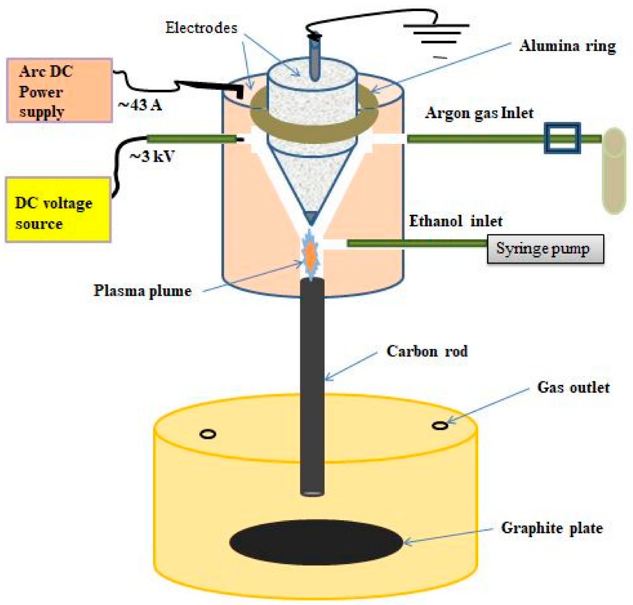
2. Experimental Procedure

Figure 1 shows the assembly of the thermal plasma jet used for the synthesis of the graphene. The thermal plasma jet was comprised of a conical steel anode (13 mm long, with the cylindrical part being 4 mm long, conical part 9 cm long and with a diameter of 12 mm). A tungsten electrode (15 mm long with a diameter of 2.5 mm) with a sharp edge, passing through the center of the steel electrode, was used to sustain high temperatures below the electrode tip. An alumina ring (with an external diameter 20 mm and an internal diameter of 12 mm) was placed around the cylindrical part of the steel electrode to separate the steel anode from the external brass cathode (discussed below). The alumina was used to avoid electrical and thermal damage. A carbon tube (with a length of 14–20 cm, and internal diameter of 5 mm) was attached at the bottom of the tungsten electrode. This was a path for the flow of carbon and its length was adjusted in such a manner that the synthesized graphene was protected from thermal damage. The whole assembly described above was placed inside the hollow cylindrical brass electrode (with a length of 34 mm, external diameter of 30 mm and internal diameter app. 20 mm) which was used as an anode. The thermal plasma jet had three inlets (an internal diameter of 3 mm); the first for the gas supply (parallel to the cylindrical part of the steel electrode), the second for the carbon source supply (parallel to the tungsten tip), and the third for the voltage input to the external electrode (parallel to the cylindrical part of the steel electrode).
In our experiments, the thermal plasma was generated by applying a high switching voltage of ~3 kV between a tungsten-centered steel cathode and a brass anode using a voltage source (JP-15). This thermal plasma was sustained by a high direct current (DC) of ~43 A using a DC power supply (ZX7-315). The thermal plasma plume flowed through a brass nozzle and an attached carbon tube, with a speed close to the velocity of sound. To avoid damage to the jet, the experiment was performed with a delay of a few minutes, so that the electrodes’ temperatures could reach just below their melting points, as shown in Figure 2. Furthermore, a graphite plate polished with sandpaper, having a diameter of 4 cm and thickness of 7 mm, was placed at the bottom of a ceramic bowl. The bowl had two holes, where the first hole was used for the insertion of the carbon tube and the second hole acted as a gas outlet. The carbon tube and graphite plate were placed perpendicular to each other and were separated by a distance varying between 1–7 cm. The substrates were attached to the walls and bottom of the ceramic container. Ethanol was used as a carbon source. Using a syringe pump (1235-N), the ethanol with a flow rate of 30 mL h−1 was continuously inserted into the plume of thermal plasma.
This generated a beam of high kinetic energy carbon atoms which collided with the graphite plate, resulting in the epitaxial growth of high-quality graphene sheets and carbon nanostructures. To avoid contamination effects on the synthesized graphene sheets, the substrates were cleaned with ethanol followed by cleaning through an ultrasonic bath for 30 min. Furthermore, humidity effects could be ruled out due to the thermal nature of the plasma process, during which the temperature was significantly increased. Two samples were prepared using different thermal plasma sources. Sample A was prepared by exposing the substrates for 2 min using Ar (99.99%) gas with a flow rate of 2 SLM as a thermal plasma source, whereas sample B was prepared with a mixture of Ar and N2 (1:1 SLM) for 2 min. The structure and morphology of the prepared graphene sheets were analyzed in detail using Raman spectroscopy, FTIR and FE-SEM analysis, respectively. In this regard, a RAMBOSS Raman spectrometer by Dong Woo Optron, South Korea, was used for the Raman measurements. An excitation laser source of 514.5 nm, with 10 mW and 3 sec of accumulation time was employed. A TESCAN MIRA3 scanning electron microscope (SEM) was used to investigate the morphology of the synthesized graphene. The Fourier transform infrared (FTIR) spectroscopy was carried out using a Shimadzu spectrometer (IRTracer-100).

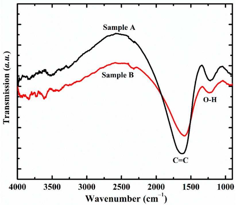
3. Results and Discussion

Raman spectroscopy is a powerful technique for understanding the structural properties of graphene-based materials. The Raman scattering measurements on the synthesized samples were performed at room temperature, with an argon ion laser as an excitation source at a wavelength of 514.5 nm. Figure 2 shows the Raman spectra of the synthesized samples. Three peaks were identified in the Raman spectrum at around 1362 cm−1, 1610 cm−1 and 2718 cm−1, which were attributed to the respective D, G and 2D peaks related to the graphene [37]. The structural defects in the graphene were identified by the peak related to the D band. This peak was observed due to the edges and broken layers of the graphene. Increasing the number of graphene layers also increased the D band height or the corresponding intensity. The G band represented the irrational modes and originated due to sp2 bond stretching in both the rings and chains. The reported value for the G peak was ~1580 cm−1. The most important peak that appeared in the Raman spectrum was the 2D band, which helped to determine the number of graphene layers. The higher intensity of the 2D peak indicated a lower number of graphene layers [38]. The 2D peak was stronger than the G peak for a monolayer, whilst it was weaker and broader for the bilayer and few-layer graphene [39]. The G peak and the 2D peaks were shifted to higher wavenumbers for the multi-layer graphene [40]. Moreover, the G band further shifted to higher wavenumbers due to the oxygenation of the graphite, which resulted in the formation of sp3 carbon atoms. This may explain the presence of the G band around 1610 cm−1 for both our samples. The 2D peak for the monolayer graphene was below 2700 cm−1, whereas for the bilayer, it appeared at 2700 cm−1, and for five layers it appeared at around 2715 cm−1. For more than ten layers it became close to 2750 cm−1, which was close to that of the graphite [33]. In our samples, the value for the 2D (~2718 cm−1) peak identified the formation of a multi-layer graphene.
The disorder in the structure of the graphene was estimated by the ID/IG value. For our synthesized samples A and B, the ID/IG values were 0.49 and 0.6, respectively, which pointed to a good quality graphene [41]. According to previous reports, numerous defects are introduced during the preparation process of graphene-based materials [42,43]. These defects are known to have a great impact on various functional properties of synthesized graphene and, thus, on its utilization in many practical applications. Since the synthesis procedure in our study involved the usage of atmospheric pressure plasma, oxygen atoms were provided by the atmosphere to bond with carbon atoms to produce graphene oxide. The structural characteristics of the samples prepared in the presence of the pure Ar and Ar–N2 mixture gases were investigated with the help of Raman spectroscopy. The presence of the D band in the Raman spectra of the prepared samples was associated with the structural defects; therefore, once the samples were prepared at optimum conditions, the defect structure was assumed to be stable at room temperature. The number of graphene layers was estimated by evaluating the IG/I2D values. We found that the IG/I2D ratio for samples A and B were 3.53 and 3.04, respectively, which corresponded to the multilayer graphene [44,45]. The addition of N2 gas with Ar improved the thermal conductivity of the mixed plasma and increased the number of molecular ions [46]. The improved thermal and electrical conductivity of the nitrogen provided better nucleation conditions and, hence, more graphene layers were obtained. This indicates that a comparatively larger number of graphene layers were synthesized in the case of the Ar–N2 mixture plasma when compared with that of the pure Ar plasma. The high reactivity of nitrogen enabled it to interact with the surroundings which may have decreased the purity of the graphene. Since the samples in the present study were synthesized under atmospheric conditions, there was a higher likelihood of contamination in the product prepared by the Ar–N2 mixture plasma than with that of the pure Ar plasma; therefore, it was expected that sample B would have more impurities than sample A. This was demonstrated by the relative intensities of the G and D bands in the Raman spectra for both samples. The value of the ID/IG for sample B was higher than that of sample A, which indicated that the Ar–N2 mixture plasma encouraged the formation of structural defects and multilayer structures. The structural defects may have involved disordered networks, topological defects, and ad-atoms [47].
The morphology of the synthesized samples was characterized using SEM, which exhibited the successful formation of multilayered graphene sheets. Figure 3a shows the SEM images of sample A synthesized via a 2 min plasma treatment using pure argon whilst Figure 3b shows the morphology of sample B prepared under the same conditions using a mixture of Ar and N2 as a source. The analysis of the morphology of sample B indicated more graphene layers when compared with sample A. These findings were in agreement with the Raman scattering measurements and indicate that as the plasma treatment time increased, ethanol dissociation took place which resulted in the stacking of graphene sheets over each other. The number of layers also depended on the plasma gas flow rate and ethanol injection rate.
Fourier transform infrared (FTIR) spectroscopy was employed to investigate the vibrational features of the synthesized samples. The measurements were performed in the range of 900 cm−1–4000 cm−1 by using a standard source at an incident angle of 45°. The FTIR spectra of sample A and sample B are shown in Figure 4. Generally, the FTIR spectra of graphene cannot be resolved below 900 cm−1 because of its structural complexity. The broad band in the range 1570–1623 cm−1 corresponded to the C=C stretching vibrations of graphene [48,49]. The appearance of a peak at 1220 cm−1 in the FTIR spectrum corresponded to the O–H stretching vibration. This indicates the vibrational mode of the graphene oxide (GO) and OH group from the phenol, which gives an identification of the presence of impurities, such as oxygen and hydrogen, in the graphene structure. The phenols are the class of compounds having a hydroxyl group directly bonded to an aromatic hydrocarbon group [48,50].

4. Conclusions

An atmospheric plasma jet system was used to synthesize graphene sheets by using pure Ar and a mixture of Ar–N2 gases as a plasma source. The corresponding structural and morphological properties of the prepared materials were investigated and discussed in detail. Raman spectroscopy confirmed the successful fabrication of graphene, revealing the presence of G and 2D peaks. We found that the use of an Ar–N2 mixture enhanced the production of the graphene sheets; however, the quality of the graphene sheets was lowered due to the reactive nature of N2 gas. The morphology of the synthesized samples studied via SEM images showed the formation of multilayered graphene, while the FTIR spectra showed the C=C and O-H stretching vibration mode. The presence of a hydroxyl group directly bonded to the aromatic hydrocarbon suggested the presence of oxygen and hydrogen, typically found in GO. We conclude that by optimizing the synthesis conditions, the atmospheric plasma jet system could be an effective and versatile method for the large-scale production of graphene-based materials.

Author Contributions

Conceptualization, N.U.R.; Formal analysis, S.u.R. and W.A.; Funding acquisition and Investigation, N.U.R. and S.u.R.; Methodology, N.U.R.; Project administration, N.U.R.; Resources, N.U.R., M.A. and E.M.T.E.D.; Supervision, N.U.R. and S.u.R.; Validation, E.M.T.E.D.; Visualization, M.A. and E.M.T.E.D.; Writing—original draft, S.u.R.; Writing—review & editing, W.A. All authors have read and agreed to the published version of the manuscript.

Funding

This research was funded by the Higher Education Commission of Pakistan grant numbers NRPU project 9899/Balochistan/NRPU/R&D/HEC/2017 and TDF-137.

Institutional Review Board Statement

Not applicable.

Informed Consent Statement

Not applicable.

Data Availability Statement

Data is contained within the article.

Acknowledgments

The authors would like to thank the Higher Education Commission of Pakistan for providing funding (NRPU project 9899/Balochistan/NRPU/R&D/HEC/2017 and TDF-137).

Conflicts of Interest

The authors declare no conflict of interest.

References

  1. Novoselov, K.S.; Jiang, D.; Schedin, F.; Booth, T.J.; Khotkevich, V.V.; Morozov, S.V.; Geim, A.K. Two-dimensional atomic crystals. Proc. Natl. Acad. Sci. USA 2005, 102, 10451–10453. [Google Scholar] [CrossRef] [PubMed] [Green Version]
  2. Stankovich, S.; Dikin, D.A.; Dommett, G.H.B.; Kohlhaas, K.M.; Zimney, E.J.; Stach, E.A.; Piner, R.D.; Nguyen, S.T.; Ruoff, R.S. Graphene-based composite materials. Nature 2006, 442, 282–286. [Google Scholar] [CrossRef]
  3. Lei, L.; Jingwei, B.; Yongquan, Q.; Yu, H.; Xiangfeng, D. Single-layer graphene on Al2O3/Si substrate: Better contrast and higher performance of graphene transistors. Nanotechnology 2010, 21, 015705. [Google Scholar]
  4. Watcharotone, S.; Dikin, D.A.; Stankovich, S.; Piner, R.; Jung, I.; Dommett, G.H.B.; Evmenenko, G.; Wu, S.-E.; Chen, S.-F.; Liu, C.-P.; et al. Graphene–Silica Composite Thin Films as Transparent Conductors. Nano Lett. 2007, 7, 1888–1892. [Google Scholar] [CrossRef] [PubMed]
  5. Wang, X.; Zhi, L.; Müllen, K. Transparent, Conductive Graphene Electrodes for Dye-Sensitized Solar Cells. Nano Lett. 2008, 8, 323–327. [Google Scholar] [CrossRef]
  6. Schedin, F.; Geim, A.K.; Morozov, S.V.; Hill, E.W.; Blake, P.; Katsnelson, M.I.; Novoselov, K.S. Detection of individual gas molecules adsorbed on graphene. Nat. Mater. 2007, 6, 652–655. [Google Scholar] [CrossRef]
  7. Kostya, O.; Uros, C.; Anthony, B.M. Plasma nanoscience: Setting directions, tackling grand challenges. J. Phys. D Appl. Phys. 2011, 44, 174001. [Google Scholar]
  8. Novoselov, K.S.; Geim, A.K.; Morozov, S.V.; Jiang, D.; Zhang, Y.; Dubonos, S.V.; Grigorieva, I.V.; Firsov, A.A. Electric field effect in atomically thin carbon films. Science 2004, 306, 666–669. [Google Scholar] [CrossRef] [Green Version]
  9. Shang, N.G.; Papakonstantinou, P.; McMullan, M.; Chu, M.; Stamboulis, A.; Potenza, A.; Dhesi, S.S.; Marchetto, H. Catalyst-Free Efficient Growth, Orientation and Biosensing Properties of Multilayer Graphene Nanoflake Films with Sharp Edge Planes. Adv. Funct. Mater. 2008, 18, 3506–3514. [Google Scholar] [CrossRef]
  10. Li, J.; Cheng, X.; Sun, J.; Brand, C.; Shashurin, A.; Reeves, M.; Keidar, M. Paper-based ultracapacitors with carbon nanotubes-graphene composites. J. Appl. Phys. 2014, 115, 164301. [Google Scholar] [CrossRef] [Green Version]
  11. Novoselov, K.S.; Jiang, Z.; Zhang, Y.; Morozov, S.V.; Stormer, H.L.; Zeitler, U.; Maan, J.C.; Boebinger, G.S.; Kim, P.; Geim, A.K. Room-Temperature Quantum Hall Effect in Graphene. Science 2007, 315, 1379. [Google Scholar] [CrossRef] [PubMed] [Green Version]
  12. Novoselov, K.S.; Geim, A.K.; Morozov, S.V.; Jiang, D.; Katsnelson, M.I.; Grigorieva, I.V.; Dubonos, S.V.; Firsov, A.A. Two-dimensional gas of massless Dirac fermions in graphene. Nature 2005, 438, 197–200. [Google Scholar] [CrossRef] [PubMed]
  13. Aïssa, B.; Memon, N.K.; Ali, A.A.; Khraisheh, M.K. Recent Progress in the Growth and Applications of Graphene as a Smart Material: A Review. Front. Mater. 2015, 2, 58. [Google Scholar] [CrossRef] [Green Version]
  14. Kim, K.S.; Zhao, Y.; Jang, H.; Lee, S.Y.; Kim, J.M.; Kim, K.S.; Ahn, J.-H.; Kim, P.; Choi, J.-Y.; Hong, B.H. Large-scale pattern growth of graphene films for stretchable transparent electrodes. Nature 2009, 457, 706–710. [Google Scholar] [CrossRef] [PubMed]
  15. Li, X.; Cai, W.; An, J.; Kim, S.; Nah, J.; Yang, D.; Piner, R.; Velamakanni, A.; Jung, I.; Tutuc, E.; et al. Large-Area Synthesis of High-Quality and Uniform Graphene Films on Copper Foils. Science 2009, 324, 1312–1314. [Google Scholar] [CrossRef] [Green Version]
  16. Berger, C.; Song, Z.; Li, X.; Wu, X.; Brown, N.; Naud, C.; Mayou, D.; Li, T.; Hass, J.; Marchenkov, A.N.; et al. Electronic confinement and coherence in patterned epitaxial graphene. Science 2006, 312, 1191–1196. [Google Scholar] [CrossRef] [Green Version]
  17. Dato, A.; Radmilovic, V.; Lee, Z.; Phillips, J.; Frenklach, M. Substrate-Free Gas-Phase Synthesis of Graphene Sheets. Nano Lett. 2008, 8, 2012–2016. [Google Scholar] [CrossRef]
  18. Wang, J.; Zhu, M.; Outlaw, R.A.; Zhao, X.; Manos, D.M.; Holloway, B.C. Synthesis of carbon nanosheets by inductively coupled radio-frequency plasma enhanced chemical vapor deposition. Carbon 2004, 42, 2867–2872. [Google Scholar] [CrossRef]
  19. Alexander, M.; Roumen, V.; Koen, S.; Alexander, V.; Liang, Z.; Van, T.G.; Annick, V.; Chris, V.H. Synthesis of few-layer graphene via microwave plasma-enhanced chemical vapour deposition. Nanotechnology 2008, 19, 305604. [Google Scholar]
  20. Schniepp, H.C.; Li, J.-L.; McAllister, M.J.; Sai, H.; Herrera-Alonso, M.; Adamson, D.H.; Prud’Homme, R.K.; Car, R.; Saville, D.A.; Aksay, I.A. Functionalized Single Graphene Sheets Derived from Splitting Graphite Oxide. J. Phys. Chem. B 2006, 110, 8535–8539. [Google Scholar] [CrossRef] [Green Version]
  21. Choucair, M.; Thordarson, P.; Stride, J.A. Gram-scale production of graphene based on solvothermal synthesis and sonication. Nat. Nanotechnol. 2009, 4, 30–33. [Google Scholar] [CrossRef] [PubMed]
  22. Becerril, H.A.; Mao, J.; Liu, Z.; Stoltenberg, R.M.; Bao, Z.; Chen, Y. Evaluation of Solution-Processed Reduced Graphene Oxide Films as Transparent Conductors. ACS Nano 2008, 2, 463–470. [Google Scholar] [CrossRef] [PubMed]
  23. Wang, H.; Robinson, J.T.; Li, X.; Dai, H. Solvothermal Reduction of Chemically Exfoliated Graphene Sheets. J. Am. Chem. Soc. 2009, 131, 9910–9911. [Google Scholar] [CrossRef] [PubMed]
  24. Geim, A.K.N.; Novoselov, K.S. The Rise of Graphene. Nat. Mater. 2007, 6, 183–191. [Google Scholar] [CrossRef]
  25. Tatarova, E.; Bundaleska, N.; Sarrette, J.P.; Ferreira, C.M. Plasmas for environmental issues: From hydrogen production to 2D materials assembly. Plasma Sources Sci. Technol. 2014, 23, 063002. [Google Scholar] [CrossRef]
  26. Levchenko, I.; Keidar, M.; Xu, S.; Kersten, H.; Ostrikov, K. Low-temperature plasmas in carbon nanostructure synthesis. J. Vac. Sci. Technol. B Nanotechnol. Microelectron. Mater. Process. Meas. Phenom. 2013, 31, 050801. [Google Scholar] [CrossRef] [Green Version]
  27. Lambert, T.N.; Luhrs, C.C.; Chavez, C.A.; Wakeland, S.; Brumbach, M.T.; Alam, T.M. Graphite oxide as a precursor for the synthesis of disordered graphenes using the aerosol-through-plasma method. Carbon 2010, 48, 4081–4089. [Google Scholar] [CrossRef]
  28. Tatarova, E.; Dias, A.; Henriques, J.; Rego, A.; Ferraria, A.M.; Abrashev, M.; Luhrs, C.C.; Phillips, J.; Dias, F.M.; Ferreira, C.M. Microwave plasmas applied for the synthesis of free standing graphene sheets. J. Phys. D Appl. Phys. 2014, 47, 385501. [Google Scholar] [CrossRef]
  29. Tatarova, E.; Henriques, J.; Luhrs, C.C.; Dias, A.; Phillips, J.; Abrashev, M.; Ferreira, C. Microwave plasma based single step method for free standing graphene synthesis at atmospheric conditions. Appl. Phys. Lett. 2013, 103, 134101. [Google Scholar] [CrossRef]
  30. Garaj, S.; Hubbard, W.; Reina, A.; Kong, J.; Branton, D.; Golovchenko, J.A. Graphene as a subnanometre trans-electrode membrane. Nature 2010, 467, 190–193. [Google Scholar] [CrossRef] [Green Version]
  31. Yamada, T.; Ishihara, M.; Kim, J.; Hasegawa, M.; Iijima, S. A roll-to-roll microwave plasma chemical vapor deposition process for the production of 294mm width graphene films at low temperature. Carbon 2012, 50, 2615–2619. [Google Scholar] [CrossRef]
  32. Kim, J.; Ishihara, M.; Koga, Y.; Tsugawa, K.; Hasegawa, M.; Iijima, S. Low-temperature synthesis of large-area graphene-based transparent conductive films using surface wave plasma chemical vapor deposition. Appl. Phys. Lett. 2011, 98, 091502. [Google Scholar] [CrossRef]
  33. Kim, J.; Heo, S.B.; Gu, G.H.; Suh, J.S. Fabrication of graphene flakes composed of multi-layer graphene sheets using a thermal plasma jet system. Nanotechnology 2010, 21, 095601. [Google Scholar] [CrossRef]
  34. Hahn, J.; Heo, S.B.; Suh, J.S. Catalyst free synthesis of high-purity carbon nanotubes by thermal plasma jet. Carbon 2005, 43, 2638–2641. [Google Scholar] [CrossRef]
  35. Fronczak, M.; Fazekas, P.; Károly, Z.; Hamankiewicz, B.; Bystrzejewski, M. Continuous and catalyst free synthesis of graphene sheets in thermal plasma jet. Chem. Eng. J. 2017, 322, 385–396. [Google Scholar] [CrossRef] [Green Version]
  36. Shavelkina, M.; Ivanov, P.; Bocharov, A.; Amirov, R. Distinctive Features of Graphene Synthesized in a Plasma Jet Created by a DC Plasma Torch. Materials 2020, 13, 1728. [Google Scholar] [CrossRef] [PubMed] [Green Version]
  37. Saito, R.; Hofmann, M.; Dresselhaus, G.; Jorio, A.; Dresselhaus, M.S. Raman spectroscopy of graphene and carbon nanotubes. Adv. Phys. 2011, 60, 413–550. [Google Scholar] [CrossRef]
  38. Ferrari, A.C.; Basko, D.M. Raman spectroscopy as a versatile tool for studying the properties of graphene. Nat. Nanotechnol. 2013, 8, 235–246. [Google Scholar] [CrossRef] [Green Version]
  39. Amirov, R.; Iskhakov, M.; Shavelkina, M. Synthesis of high-purity multilayer graphene using plasma jet. Nanosyst. Phys. Chem. Math. 2016, 7, 60–64. [Google Scholar] [CrossRef] [Green Version]
  40. Ferrari, A.C. Raman spectroscopy of graphene and graphite: Disorder, electron–phonon coupling, doping and nonadiabatic effects. Solid State Commun. 2007, 143, 47–57. [Google Scholar] [CrossRef]
  41. Lee, B.-J.; Cho, S.-C.; Jeong, G.-H. Atmospheric pressure plasma treatment on graphene grown by chemical vapor deposition. Curr. Appl. Phys. 2015, 15, 563–568. [Google Scholar] [CrossRef]
  42. Banhart, F.; Kotakoski, J.; Krasheninnikov, A.V. Structural Defects in Graphene. ACS Nano 2011, 5, 26–41. [Google Scholar] [CrossRef] [PubMed] [Green Version]
  43. Tian, W.; Li, W.; Yu, W.; Liu, X. A Review on Lattice Defects in Graphene: Types, Generation, Effects and Regulation. Micromachines 2017, 8, 163. [Google Scholar] [CrossRef]
  44. Hou, W.; Wang, J.; Wang, Z.; Cao, K.; Qin, L.; Wang, L. Growth of few-layer graphene on Cu foil by regulating the pressure of reaction gases. CrystEngComm 2020, 22, 1018–1023. [Google Scholar] [CrossRef]
  45. Kai, S.; Junhong, S. Effects of different preparation processes on the transparent electromagnetic shielding performance of graphene. In Proceedings of the Twelfth International Conference on Information Optics and Photonics, Xi’an, China, 1 November 2021; p. 120571H. [Google Scholar]
  46. Rankovic, D.; Kuzmanović, M.; Pavlović, M.S.; Stoiljković, M.; Savovic, J. Properties of Argon–Nitrogen Atmospheric Pressure DC Arc Plasma. Plasma Chem. Plasma Process. 2015, 35, 1071–1095. [Google Scholar] [CrossRef]
  47. Dato, A. Graphene synthesized in atmospheric plasmas—A review. J. Mater. Res. 2019, 34, 214–230. [Google Scholar] [CrossRef] [Green Version]
  48. Ţucureanu, V.; Matei, A.; Avram, A.M. FTIR Spectroscopy for Carbon Family Study. Crit. Rev. Anal. Chem. 2016, 46, 502–520. [Google Scholar] [CrossRef]
  49. Lecaros, R.L.; Mendoza, G.E.J.; Hung, W.-S.; An, Q.-F.; Caparanga, A.R.; Tsai, H.-A.; Hu, C.-C.; Lee, K.-R.; Lai, J.-Y. Tunable interlayer spacing of composite graphene oxide-framework membrane for acetic acid dehydration. Carbon 2017, 123, 660–667. [Google Scholar] [CrossRef]
  50. Gao, W. Graphene Oxide: Reduction Recipes, Spectroscopy, and Applications; Springer International Publishing: Berlin, Germany, 2015. [Google Scholar]
Figure 1. The schematic diagram of the thermal plasma jet system.
Energies 15 07245 g001
Figure 2. Comparison of Raman spectra of graphene synthesized by pure Ar (sample A) and Ar–N2 mixture plasma (sample B).
Energies 15 07245 g002
Figure 3. SEM images of the prepared graphene samples: (a) sample A, synthesized at 40 A current with pure Ar gas; and (b) sample B, fabricated by using a mixture of Ar and N2.
Energies 15 07245 g003
Figure 4. FTIR spectra of synthesized graphene samples.
Energies 15 07245 g004
Publisher’s Note: MDPI stays neutral with regard to jurisdictional claims in published maps and institutional affiliations.

