1. Introduction
Groundwater in rock and soil increases the hydrodynamic and hydrostatic pressure of the rock and soil and also decreases its strength. About 90% of landslides are rain-induced, which demonstrates the important influence of water on slope stability [
1]. Water is also an important influence on slope deformation and instability in slope engineering; therefore, a continuous and effective drainage system may be useful in guaranteeing slope safety [
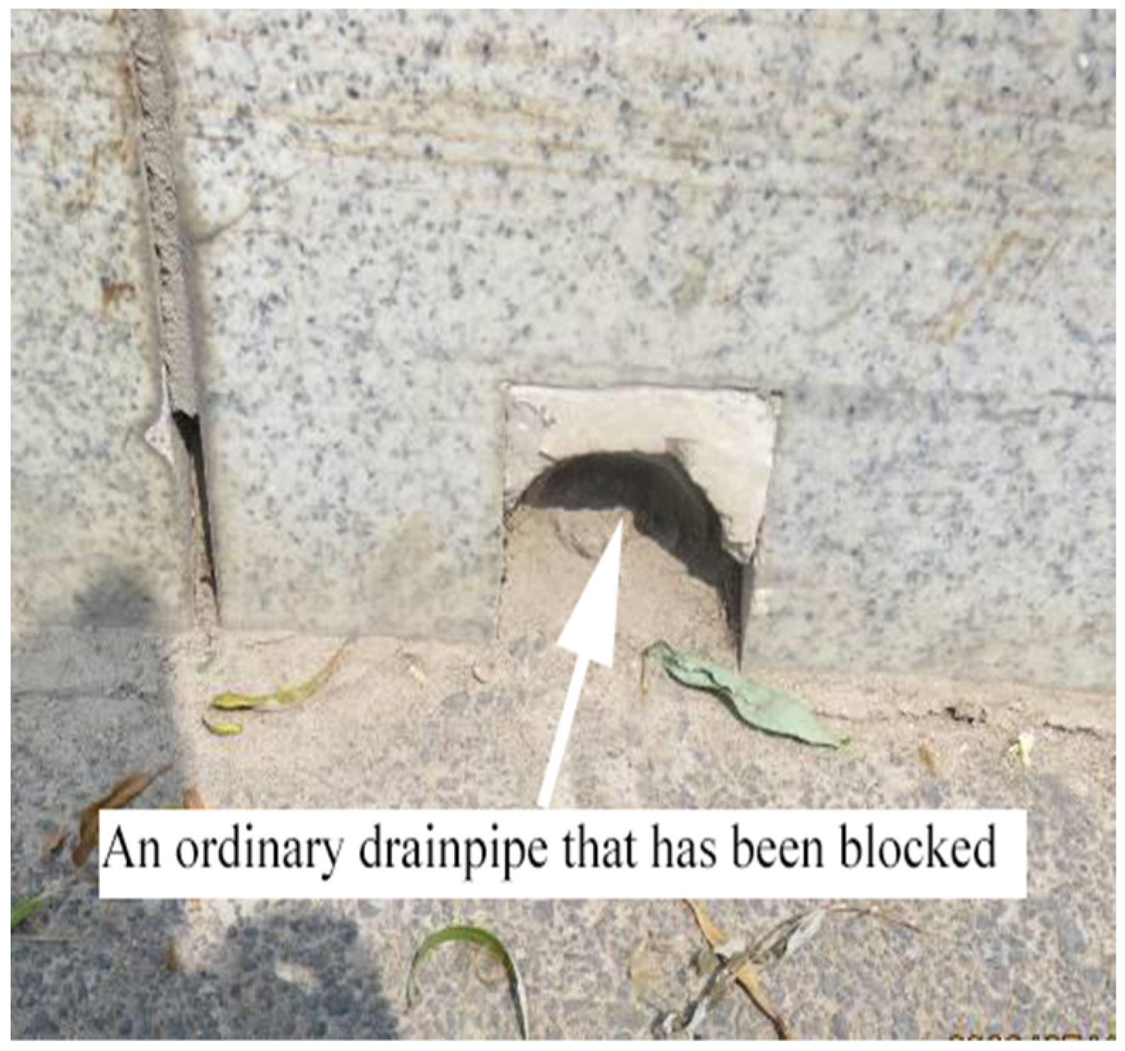
2]. The ordinary drainage pipes often used in slope engineering are prone to blockage by mud and sand in their middle and late stages of operation, resulting in poor drainage or complete failure [
3]. During the construction design, it is assumed that the drainage system is operating normally. However, there may be risks to slope stability that are buried and remain unseen.
Figure 1 is a block diagram of ordinary drainage pipes, while
Figure 2 shows the arrangement of drainage pipes in a retaining wall.
There have been many studies on slope drainage based on laboratory tests, numerical modelling, field tests and theoretical analysis. For example, Jiang and Guo used comprehensive drainage measures, such as pavement and subgrade drainage, to achieve good results with certain practical value [
4]. Jiang integrated subgrade and pavement drainage measures to ensure the integrity and systematicity of drainage facilities [
5]. Akay used EPS geofoam as a soil substitute filler in slope rehabilitation works and proposed that the use of internal drainage systems increases the safety factor of slope systems under water seepage conditions [
6]. Dong et al. proposed the use of no-fines concrete or inverted filter geotextiles to improve the inverted filter structure of drain holes in retaining walls, which proved very effective in engineering applications [
7]. Tian and Ye et al. used physical simulation methods to study the anti-blocking characteristics of new drainage holes in highway slopes, and crystallization and blockage in under-construction tunnel drainage systems. This provided a reference for future field applications of new drainage holes [
8,
9]. Li Chunxiao et al. introduced a new type of composite road drainage network and showed that it significantly improved the road’s performance and service life [
10]. Zhang Sulei et al. used drainage tests to show that capillary permeable drainage pipes have good anti-blocking ability [
11]. Singh et al. proposed a steel pipe system with drainage and reinforcement functions, which can quickly drain seepage water [
12]. Guo et al. proposed a new drainage device that provides another way to solve the poor drainage of existing cutting slopes and retaining walls [
13]. Moreover, Zhang Luqing et al. proposed fibre bundle seepage drainage holes, which provide long-term effective drainage of blocked drainage pipes [
14]. Miura et al. studied drainage conditions under the influence of blocked drainage pipes.
There were two main causes of significant reductions in slope drainage volume. One was creep of the filter fibre and the other was blockage of the drainage pipes due to the deposition of fine particulate matter [
15]. Under silting conditions, the initial discharge of the drainage pipe decreases greatly at first and then decreases slowly with silting at later stages [
16,
17]. Through numerical simulation, Crenshaw concluded that different types of drainage pipes have different drainage mechanisms and layouts, which lead to changes in drainage speed [
18]. D’Acunto et al. used a 2D free boundary numerical model to simulate the drainage effect of drainage holes in a slope [
19]. Cook et al. argued that the spacing of drainage holes and the permeability of slope soil are closely related to the variation in groundwater level [
20]. Tao et al. found that the particles in low-porosity soil do not readily fall off [
21].
To summarize, although some scholars have made preliminary explorations of fibre bundle seepage drainage in the field of slope drainage, their research methods are relatively simple. No studies have explored the seepage effect and the influences of fibre bundle drainage pipes via a combination of numerical simulations and laboratory tests. Hence, it is difficult to accurately determine the seepage mechanism of fibre bundle drainage pipes.
To make up for the deficiencies of existing research, this paper established a particle flow numerical model by using PFC to simulate the degree of blockage due to soil particles on a geotextile filter layer and in a drainage pipe. The influences of water pressure, hole spacing, soil internal friction angle and drainage pipe inclination angle were explored. Combined with laboratory tests, this paper probed the influences of fibre bundle type, arrangement, quantity, soil properties and drainpipe diameter on the seepage effect of fibre bundle drainage pipes under conditions where soil can accumulate in the pipe. The results reveal the seepage mechanism of fibre bundle drainage pipes. The purpose of this paper was to provide an optimization scheme for solving the problem of non-water diversion after drainage pipes become blocked.
2. Numerical Simulation of Particle Flow
2.1. Soil Particle Drainage Shedding Model
A drainage shedding model of soil particles was established using PFC2D software (5.00.25). The modelling steps were as follows: (1) Establish a closed wall “generate particles in the wall” to give the properties of particle homogeneous sand “to apply self-weight stress to complete the initial calculation. (2) Delete the surrounding closed wall to establish a vertical wall on the side, and establish two walls with a certain interval (interval distance = 1 cm) on the bottom surface (to simulate the flower hole in the drainage pipe). “Set up water pressure below the model height of 5 m” to apply self-weight stress to simulate the state of soil particles gushing out of the flower hole of the drainage pipe (that is, the wall gap). The size of the model was 4 m × 7 m. The physical and mechanical parameters of the soil particles are shown in
Table 1. The soil particle size is shown in
Table 2. The model is shown in
Figure 3 and
Figure 4.
2.2. Drainage Pipe Blockage Model
The drainage pipe model shown in
Figure 5 was established, in which the length of the drainage pipe is 3 m and the diameter of the drainage hole is 0.1 m. The soil particles fall freely from the top of the drainage pipe at a distance of 0.6 m from its closed end. A wall model with a height of 0.01 m was established at 1.5 m in the centre of the drainage pipe to simulate a soil ridge blocking the outflow of particles.
3. Analysis of Simulation Results
3.1. Effect of Water Pressure on Drainage Shedding of Soil Particles
It can be seen from
Figure 6 that the number of shedding soil particles increases gradually with increases in pore water pressure at the opening. The analysis shows that the greater the water pressure, the greater the hydraulic gradient between the soil along the height direction, the pore water pressure in the soil and the water pressure in the drainage pipe. The hydraulic gradient has a certain impact on blockage of the drainage filter layer. When the hydraulic gradient is high, finer particles are carried by seepage and a large number will be deposited in the interior and surface of the geotextile filter layer, resulting in blockage of the filter layer. So, the greater the hydraulic gradient, the more easily blockage of the drainage filter layer occurs and the worse the drainage effect [
22].
3.2. Effect of Opening Spacing on Drainage Shedding of Soil Particles
As can be seen from
Figure 7 and
Figure 8 and
Table 3 that when the hole spacing is 0.5 cm, 1 cm, 2 cm, 3 cm, 4 cm and 5 cm, the number of soil particles shed is 1590, 980, 890, 865, 850, and 850, respectively. It reflects that the number of shed soil particles decreases with the increases in hole spacing. In the process of soil particle shedding at the front of the flower hole in the drainage pipe, a “micro soil arch” can easily form, which restrains soil particle shedding. If the hole spacing is too close, there is a trend of penetration between two similar “micro soil arches”. As the opening distance continues to decrease, the two “micro soil arches” become connected, resulting in a sharp increase in the number of shed soil particles. This readily causes silting in the geotextile filter layer, which reduces drainage performance. It can also be seen from
Figure 8 that there is an inverse logarithm function relationship between the shedding number of soil particles and the opening distance when the opening space is larger than 0.5 cm, and the optimal value (the curve inflection point) is about 3 cm. This analysis shows that the hole spacing in the drainage pipe should be about 3 cm. In addition, soil with different properties may have a different penetration range, causing the optimal position to also be different.
3.3. Effect of Soil Friction Angle on Drainage Pipe Blockage
In the simulation, the soil friction angles were 20°, 30° and 40°, respectively, while the other soil parameters remained unchanged. It can be seen from
Figure 9 that the greater the soil friction angle, the higher the soil particle accumulation height near the soil ridge. According to the analysis, the internal friction angle can be summarized as the sliding friction that needs to be overcome when the soil particles slide with each other, which is mainly affected by the roughness of the particle surfaces, the embedding of particles, and interlocking and detaching from the occlusal state. The greater the internal friction angle is, the stronger the occlusal action between particles and the less vulnerable they are to the impact of water flow. This makes them accumulate readily in the drainage pipe, resulting in blockage. In real applications, a suitable soil buried drainage pipe can be selected for better drainage.
3.4. Influence of Drainage Pipe Inclination Angle on Blockage
When the tilt Angle of the drainpipe is 0°, 5°, and 10° (
Figure 10), the number of soil particles blocked is 248, 130, and 112, respectively. As can be seen from
Figure 11, when the tilt Angle of the drainpipe increases from 0° to 5°, the number of soil particles blocked decreases from 248 to 130, which decreases by 118. When the tilt Angle of the drainage pipe increases from 5° to 10°, the number of soil particle clogging decreases from 130 to 112 by 18°. In other words, with the increase of the inclination Angle of the drain pipe, the number of clogged soil particles gradually decreases, and according to the slopes of the two line segments, the reduction amount of clogged soil particles decreases. This shows that blockage of a horizontal drainpipe is more serious than that of an inclined one. The analysis shows that after a drainage pipe is inclined, the sliding friction that needs to be overcome when the soil particles slide with each other is offset; hence, the particles do not readily accumulate under water flow. Therefore, in practical applications, drainage pipes should be inclined and buried properly.
4. Test Methods
With reference to the literature and actual projects, this study selected five types of fibre bundles with the same diameter: plastic rope, hemp rope, polyester rope, nylon rope and cotton rope. They were each arranged and fixed in a drainage pipe according to the design method. Then, the pipes were filled with soil and vibrated to simulate the blocked state. The test was started after the device was installed and debugged, and the actual seepage flows of the fibre-bundle drainage pipes under various influences were recorded. Finally, the influences of various factors on the drainage effect in these pipes were analysed according to the measured flow, as shown in the following section.
4.1. Test Program
The following three test programs were designed to consider the various factors that may affect the drainage performance of fibre bundle drainage pipes:
(1) Program for testing fibre bundle drainage pipe performance considering the influences of fibre bundle type and quantity.
In the experiment, the diameter of each fiber bundle was the same, and 6, 8, 10 and 12 fiber bundles were placed in each drain pipe to conduct a comparative test to find out the influence of different types and quantities of fiber bundles on the drainage effect, and to find out the fiber bundles with more economical types and quantities and better drainage effect. At the same time, a set of drainage pipes without fibre bundles was set up for comparison.
Table 4 shows the material specifications and uses, and
Figure 12 is a test diagram of a fibre bundle drainage pipe.
Table 4.
The material specifications and uses.
Table 4.
The material specifications and uses.
| Devices and Materials | Uses | Material Quality | Diameter/mm | Length/mm |
|---|
| Fiber bundle | for seepage in pipes | polyester rope, hemp rope, cotton rope, nylon rope, plastic rope | 2–3 | 50 |
| Head pipe | provide 0.6 m high head pressure | transparent hard plastic tube | 46 | 600 |
| drainage pipe | simulate horizontal drilling | polyvinyl chloride (PVC)pipe | 50 | 400 |
| drainage pipe (Figure 13) | balance the atmospheric pressure | polyvinyl chloride (PVC)pipe | 30 | 100 |
| filter cloth (Figure 14) | simulated geotextile to prevent soil particle loss | plastic cloth | / | 70 |
Figure 13.
A diagram of a three-way drainage pipe balancing atmospheric pressure.
Figure 13.
A diagram of a three-way drainage pipe balancing atmospheric pressure.
Figure 14.
An arrangement of simulated geotextile for the fiber bundle drainage pipe.
Figure 14.
An arrangement of simulated geotextile for the fiber bundle drainage pipe.
(2) Program for testing fibre bundle drainage pipe performance considering fibre bundle arrangement.
A group of drainage pipes are not provided with fiber bundles. The other group drainpipes were set with plastic rope, twine rope, polyester rope, nylon rope and cotton rope respectively, and the layout of each fiber bundle can be divided into two types: uniform layout and uneven layout. The control test was carried out under the condition that the pipe diameter was the same, the tube was not splined and the tube was filled with silty clay. Through the above experiments, it is expected to find a better way for this kind of fiber bundle to conduct water.
(3) Program for testing fibre bundle drainage pipe performance considering the influences of drainage pipe diameter, soil properties and strand-shaped fibre bundles.
A test of drainage pipe performance was conducted with different pipe diameters, soil properties and strand-shaped fibre bundles (3 fibre bundles twisted into 1 strand) in the soil-filled state, so as to determine their influences on the seepage effect (measured as seepage flow rate). The specific test program is shown in
Table 5.
4.2. Test Method and Process
To measure the specific seepage flow rates of the fibre bundle drainage pipes under different influences in the soil-filled state, the specific test method was as follows. (1) Arrange and fix the fibre bundle in the drainage pipe, (2) install the test device, (3) conduct the test and record the seepage flow and (4) analyse the data.
Arrangement and fixation of fibre bundles. The type and number of fibre bundles were determined to ensure that the cross-sectional area of the fibre bundles was almost the same. The relative spatial positions of the fibre bundles were arranged according to the design plan. As shown in
Figure 15, the left end of a fibre bundle was passed through the No. 1 sieve hole of the left sieve and then tied to ensure that it could not pass through the sieve again on the right side. The right end of the fibre bundle was then passed from the left side of the drainage pipe through the No. 1 sieve hole of the right sieve on the right side, and then a knot was tied at the sieve. These steps were repeated to install the designed number of fibre bundles in the corresponding position so that each fibre bundle was arranged straight in the pipe.
Figure 16 shows the uniform and uneven distribution of fiber bundles in the pipeline.
Filling of the fibre bundle drainage pipe. A sieve was placed on the ground with the lower end of the drainage pipe placed against it. The pipe was filled with test soil from the upper outlet and vibrated with a stick while filling to ensure an even soil density and to achieve blockage of the pipe. The soil was filled up to the position of the upper outlet. Then, the pipe was turned over and the lower end was filled with test soil according to the same method. It was ensured that the fibre bundle was in a straightened state during soil-filling. The excess fibre bundle outside the pipe outlet was cut after filling, then simulated geotextile was wrapped around the pipe outlet and adhered to it with glue. The quality of the drainage pipe was then measured with a balance. The drainage pipe was installed on the side of a six-way pipe outlet, the four sides of which were filled with soil.
(1) Installation of the drainage pipe test device. The six-way outlet was installed with a head pipe with a design height on the top and a section of PVC pipe at the bottom. The lower part of the PVC pipe was plugged with a pipe cap to prevent water leakage. A three-way pipe was installed at the top of the head pipe with a water inlet pipe at one end of the three-way pipe and a water outlet pipe at the other end. A small opening was made on the three-way pipe to balance the atmospheric pressure and maintain the height of the water pressure. A measuring cup was placed under the outlet of each drainage pipe. Then, the faucet was turned on to observe whether the device leaked. If water leakage occurred, the faucet was turned off and the device was fastened again. The test timing was started when no water leakage occurred, the height of the water pressure was unchanged and the drainage pipe was stable.
(2) Recording of seepage flow rate and data analysis. The faucet was turned off and the measuring cups were removed when the designated test time was reached. The water volumes in the measuring cups under each fibre bundle drainage pipe were measured. The seepage flow rates of the drainage pipes were determined and analysed in relation to the different test factors.
5. Results
The test data were analysed to determine the parameters providing optimal drainage performance. Please note that the experimental data are the average of 8 group experiments.
5.1. Influences of the Type and Quantity of Fibre Bundles
Tests were conducted with different types and quantities of fibre bundles to observe the effects on seepage flow. This helped determine the type of fibre bundle that provides the most significant drainage effect.
It can be seen in
Table 6 that the seepage flow was much greater in drainage pipes containing a fibre bundle than in an ordinary drainage pipe in the soil-filled state. This shows that a fibre bundle pipe provides better drainage than an ordinary blocked drainpipe. As the space in a drainage pipe is limited, the number of fibre bundles with drainage effect in the drainage pipe increased with an increasing number of fibre bundles, thereby helping to increase the seepage flow of the blocked drainage pipe. So, this type of fibre bundle has an ideal drainage effect.
Figure 17 shows that pipes with unevenly arranged fibre bundles had a generally better seepage effect than pipes with evenly arranged fibre bundles (for plastic rope or cotton rope fibre bundles with the same number of fibres). This is because an uneven arrangement of this type of fibre provides better drainage and can increase the seepage flow of a blocked drainage pipe.
Table 6 indicates that water will drain out of a pipe when a hemp rope fibre bundle is soaked with water. When the number of fibre bundles increases from 6 to 12, the seepage flow increases from 360 mL/h to 1430 mL/h. This is an increase of nearly 1070 mL/h, showing greatly improved drainage efficiency. The seepage flows of the drainage pipes with polyester rope fibre bundles were low with 6, 8, 10 and 12 strands, indicating that this type of fibre bundle provides a bad drainage effect and is unable to significantly improve drainage efficiency compared with the soil-filled state. The nylon rope fibre bundles, arranged evenly or unevenly under a soil-filled state provided no significant increases in seepage flow compared with the control group (without fibre bundles), indicating that nylon rope fibre bundles provide a relatively weak drainage capability.
Figure 18 indicates that the seepage flow rate of the blocked drainage pipe increased with increasing numbers of fibre bundles. The quantity of hemp rope fibre had a great influence on the seepage flow rate.
Figure 18 shows that the seepage flow rates of evenly arranged polyester rope fibre bundles were much greater than those of unevenly arranged ones, indicating that the former is more effective.
Figure 19 shows that the seepage flow rates of nylon rope fibre bundles were greater when evenly arranged than when unevenly arranged, indicating that the former is more effective.
According to
Figure 20, when various types of fibre bundles are evenly arranged in soil-filled drainage pipes, the seepage flow rate gradually increases with the number of fibre bundles. Plastic rope and then hemp rope fibre bundles had the best drainage effect. The various fibre bundles can be ranked from strongest to weakest effect as: plastic rope > hemp rope > polyester rope > cotton rope > nylon rope. The drainage effect of cotton rope will be greater than that of polyester rope when the fibre bundles are arranged to maximize their effect.
5.2. Influences of Pipe Diameter, Strand-Shaped Fibre Bundle and Soil Properties
For a given number of cotton rope fibre bundles arranged unevenly in soil-filled drainage pipes of different diameters,
Table 6 and
Figure 21 show that the average seepage flow rate is about 57 mL/h greater in the smaller diameter pipe than in the larger diameter one. Because the fibre bundles conduct permeation, using more fibre bundles per unit cross-sectional area of pipe provides better drainage.
Table 6 and
Figure 22 show that the seepage flow rate of a pipe with a strand-shaped hemp rope (with three hemp rope fibre bundles twisted into one strand) was less than that of a pipe with an unstranded hemp rope and provided poor seepage efficiency. Hemp rope fibre bundles that are not twisted into a strand have a larger contact area with the soil in the pipe than strand-shaped bundles for a given number of bundles; therefore, the former has the better seepage effect. At the same time, evenly arranged hemp rope fibre bundles provide a better seepage effect than unevenly arranged ones because they can conduct drainage better under the soil-filled state. According to
Table 6, the plastic rope fibre bundle provides a better seepage effect when unevenly arranged than when evenly arranged. Therefore, the uneven arrangement method was chosen to compare the drainage function of fibre bundles under different soil properties.
Figure 23 shows that in the soil-filled state, the seepage effect of the plastic rope drainage pipe with silty clay plus 25% sand is better than that of silty clay without sand. The higher the sand content of the soil in the pipe, the greater the seepage coefficient of the soil, the better the drainage effect of the fibre bundles and the higher the seepage flow.
6. Discussion
This paper carried out engineering tests at a high-filled subgrade project at the intersection of Lushan Avenue and Zhangxin Road in Zibo City, Shandong Province. The project site receives heavy rainfall in summer. Therefore, drainage pipes were installed in the retaining wall for water drainage. To ensure the long-term performance of the drainage pipes and the safety of the subgrade, fibre bundle drainage pipes were used in the drainage structure of the retaining wall (
Figure 24).
PVC pipes (diameter = 100 mm) with fibre bundle drainage were used. There were 20 fibre bundles arranged evenly in each pipe, which was outward-inclined by 5%.
Figure 25 represents the site arrangement of the drainage pipes, while
Figure 26 shows the fibre bundle arrangement.
These pipes showed a great drainage effect after being blocked by mud and sand during a later rainfall period. They greatly reduced the potential safety hazards of the project. It provides a reference for the design and construction of similar projects.
7. Conclusions
To solve engineering problems such as geotextile blockages and soil accumulation in ordinary drainage pipes, and to ensure smooth flow in slope drainage systems, this paper proposes the idea of installing fibre bundles in drainage pipes. Particle flow simulations of the influence of soil particles on the geotextile filter layer and of drainage pipe flow rates under different influences were carried out by PFC. The concrete seepage effect and influences on fibre bundle drainage pipes were also studied by laboratory tests. The main conclusions are as follows:
(1) The greater the water pressure, the greater the pore water pressure and internal hydraulic gradient in the soil, and the easier it is to block the drainage filter layer, resulting in poor drainage. If the distance between the flower holes in the drainage pipe is too close and the “micro-soil arches” are connected, the amount of soil particle shedding will increase sharply, which can easily cause silting in the geotextile filter layer and is not conducive to drainage.
(2) The greater the soil friction angle, the more easily a drainage pipe is blocked. Pipes can be buried in soil with a smaller internal friction angle to achieve better drainage. The greater the inclination angle of the drainage pipe, the more difficult it is for soil particles to accumulate within it; hence, drainage pipes should be appropriately tilted when buried.
(3) The laboratory tests show that fibre bundle drainage pipes provided better drainage than ordinary drainage pipes in the soil-filled state. In a fibre bundle drainage pipe with a diameter of 50 mm, the drainage improvement of fibre bundles can be ranked from strong to weak as: plastic rope > hemp rope > polyester rope > cotton rope > nylon rope.
(4) The plastic rope and cotton rope fibre bundles provided better drainage effects in soil-filled pipes when they were unevenly arranged, while the nylon rope, hemp rope and polyester rope fibre bundles provided better drainage when evenly arranged.
(5) The greater the number of fibre bundles arranged in drainage pipes of a given diameter, the better the drainage performance. For a given number of fibre bundles, the drainage effect is better in a pipe with a smaller diameter than a larger one; that is, a greater number of fibre bundles per unit cross-sectional area is more conducive to drainage.
(6) The higher the ratio of sand to soil in the drainage pipe, the better the seepage effect. Therefore, the service life of drainage pipes can be prolonged by filling the gravel filter layer behind the drainage pipe with medium-coarse sand.
Author Contributions
Conceptualization, S.Z. and G.Z.; methodology, G.Z. and G.R.; formal analysis, G.R.; investigation, Z.R. and C.X.; writing—original draft preparation, Y.G.; writing—review and editing, S.Z. and G.Z.; project administration, S.Z. and G.R.; funding acquisition, S.Z. All authors have read and agreed to the published version of the manuscript.
Funding
This study was supported by the National Natural Science Foundation (grant no. 51108252) and the Shandong Transportation Science and Technology Project (grant no. 2017B59).
Data Availability Statement
The data supporting reported results can be found by contacting the corresponding author (
g_j_zhang@cumt.edu.cn).
Acknowledgments
The authors gratefully acknowledge the experimental site support from Zibo project department of Shandong Hi-Speed Group Co., Ltd. We also thank for the staff who work in the lab. They help us transport experimental materials and set up experimental equipment. At last, we are grateful to the editors and reviewers who have made a great contribution to the improvement of the article quality.
Conflicts of Interest
The authors declare no conflict of interest.
References
- Ghiassian, H.; Ghareh, S. Stability of sandy slopes under seepage conditions. Landslides 2008, 5, 397–406. [Google Scholar] [CrossRef]
- Wen, Q.Z. The value of rock and soil parameters of landslide. J. China Foreign Highw. 2009, 3, 45–47. [Google Scholar]
- Shen, B.; Ai, C.L. Mountain Area Highway Drainage and Water Damage Survey and Analysis. J. Highw. Transp. Res. Dev. 2006, 10, 5–9. [Google Scholar]
- Jiang, Y.H.; Guo, X.C. Drainage design for urban roads. J. Hefei Univ. Technol. (Nat. Sci.) 2007, 10, 1341–1344, 1348. [Google Scholar]
- Jiang, T. Highway Drainage Techniques in Collapsible LOESS Areas. Master’s Thesis, Chang’an University, Xi’an, China, 2006. [Google Scholar]
- Akay, O. Slope stabilisation using EPS block geofoam with internal drainage system. Geosynth. Int. 2016, 23, 9–22. [Google Scholar] [CrossRef]
- Dong, H.W.; Fu, G.H. Research on retaining wall drainage technology. Highway 2007, 1, 5–8. [Google Scholar]
- Tian, Q.Y.; Qian, N.G.; Hao, Z.Y. Laboratory test study on mechanical silting of a new type of inclined drainage hole in highway slope. Highway 2016, 7, 39–44. [Google Scholar]
- Ye, F.; Tian, C.M.; He, B.; Zhao, M.; Wang, J.; Han, X.B.; Song, G.F. Experimental Study on Scaling and Cloggingin Drainage System of Tunnels under Construction. China J. Highw. Transp. 2021, 3, 159–170. [Google Scholar]
- Li, C.X.; Guo, S.C.; Gao, K. Application of geotechnical drainage materials in pavement and subgrade drainage. J. China Foreign Highw. 2005, 6, 133–136. [Google Scholar]
- Zhang, S.L.; Feng, Q.Z.; Ying, G.G.; Zhang, D.L. Study of Causes of Highway Tunnel Leakage and Field Test of New Drainage Material. J. Highw. Transp. Res. Dev. 2013, 10, 86–91, 140. [Google Scholar]
- Singh, J.; Horikoshi, K.; Mochida, Y.; Takahashi, A. Centrifugal tests on minimization of flood-induced deformation of levees by steel drainage pipes. Soils Found. 2019, 59, 367–379. [Google Scholar] [CrossRef]
- Guo, Y.; Leng, W.; Nie, R.; Zhao, C.; Zhang, X. Laboratory evaluation of a new device for water drainage in roadside slope along railway systems. Geotext. Geomembranes 2018, 46, 897–903. [Google Scholar] [CrossRef]
- Zhang, L.Q.; Yang, Z.F.; Liu, D.A.; Shang, Y.J. A new drainage technique of long-term efficiency for slope and underground engineering. J. Eng. Geol. 2007, 3, 395–398. [Google Scholar]
- Miura, N.; Chai, J. Discharge Capacity of Prefabricated Vertical Drains Confined in Clay. Geosynth. Int. 2000, 7, 119–135. [Google Scholar] [CrossRef]
- Santi, P.M.; Hewitt, K.; VanDine, D.F.; Barillas Cruz, E. Debris-flow impact, vulnerability, and response. Nat. Hazards 2010, 56, 371–402. [Google Scholar] [CrossRef]
- Mininger, K.T.; Sand, P.M.; Short, R.D. 2010 AEG Outstanding Student Professional Paper Life Span of Horizontal Wick Drains Used for Landslide Drainage. Environ. Eng. Geosci. 2011, 17, 103–121. [Google Scholar] [CrossRef]
- Crenshaw, B.A. Water Table Profiles in the Vicinity of Horizontal Drains. Environ. Eng. Geosci. 2004, 10, 191–201. [Google Scholar] [CrossRef]
- D’Acunto, B.; Parente, F.; Urciuoli, G. Numerical models for 2D free boundary analysis of groundwater in slopes stabilized by drain trenches. Comput. Math. Appl. 2006, 53, 1615–1626. [Google Scholar] [CrossRef][Green Version]
- Cook, D.I.; Santi, P.M.; Higgins, J.D. 2007 AEG Student Professional Paper: Graduate Division: Horizontal Landslide Drain Design: State of the Art and Suggested Improvements. Environ. Eng. Geosci. 2008, 14, 241–250. [Google Scholar] [CrossRef]
- Tao, J.L.; Tao, H. Factors Affecting Piping Erosion Resistance: Revisited with a Numerical Modeling Approach. Int. J. Geomech. 2017, 17, 04017097. [Google Scholar] [CrossRef]
- Liu, Z.Y. Effect of Hydraulic Gradient on Clogging of Filter Layer of Landslide Drilling Drainage System. Master’s Thesis, Zhejiang University, Zhejiang, China, 2020. [Google Scholar]
Figure 1.
A block diagram of the ordinary drainage pipe.
Figure 1.
A block diagram of the ordinary drainage pipe.
Figure 2.
An arrangement diagram of the drainage pipe in the retaining wall.
Figure 2.
An arrangement diagram of the drainage pipe in the retaining wall.
Figure 3.
Soil particles.
Figure 3.
Soil particles.
Figure 5.
A drainage pipe model (unit: m).
Figure 5.
A drainage pipe model (unit: m).
Figure 6.
The effect of water pressure on drainage and shedding of soil particles.
Figure 6.
The effect of water pressure on drainage and shedding of soil particles.
Figure 7.
A displacement vector and contact force chain diagram of soil particles with different spacing. (a) opening spacing 0.5 cm. (b) opening spacing 1 cm. (c) opening spacing 2 cm.
Figure 7.
A displacement vector and contact force chain diagram of soil particles with different spacing. (a) opening spacing 0.5 cm. (b) opening spacing 1 cm. (c) opening spacing 2 cm.
Figure 8.
The effect of hole spacing on drainage shedding of soil particles.
Figure 8.
The effect of hole spacing on drainage shedding of soil particles.
Figure 9.
The effect of internal friction angle on blockage of drainage pipe. (a) Internal friction angle 20°. (b) Internal friction angle 30°. (c) Internal friction angle 40°.
Figure 9.
The effect of internal friction angle on blockage of drainage pipe. (a) Internal friction angle 20°. (b) Internal friction angle 30°. (c) Internal friction angle 40°.
Figure 10.
The different inclination angles of drainage pipes. (a) tilt angle 0°. (b) tilt angle 5°. (c) tilt angle 10°.
Figure 10.
The different inclination angles of drainage pipes. (a) tilt angle 0°. (b) tilt angle 5°. (c) tilt angle 10°.
Figure 11.
A statistical diagram of the number of clogged soil particles in the drainage pipe at different inclination angles.
Figure 11.
A statistical diagram of the number of clogged soil particles in the drainage pipe at different inclination angles.
Figure 12.
A test diagram of the fiber bundle drainage pipe.
Figure 12.
A test diagram of the fiber bundle drainage pipe.
Figure 15.
A schematic diagram of the fiber bundle drainage pipe arrangement.
Figure 15.
A schematic diagram of the fiber bundle drainage pipe arrangement.
Figure 16.
A schematic diagram of the fiber bundle in the drainage pipe. (a) even arrangement. (b) uneven arrangement.
Figure 16.
A schematic diagram of the fiber bundle in the drainage pipe. (a) even arrangement. (b) uneven arrangement.
Figure 17.
A seepage effect diagram of the plastic/cotton rope fiber bundle.
Figure 17.
A seepage effect diagram of the plastic/cotton rope fiber bundle.
Figure 18.
A seepage effect diagram of the Hemp/polyester rope fiber bundle.
Figure 18.
A seepage effect diagram of the Hemp/polyester rope fiber bundle.
Figure 19.
A seepage effect diagram of the nylon rope fiber bundle.
Figure 19.
A seepage effect diagram of the nylon rope fiber bundle.
Figure 20.
The comparison of seepage flow of different types of fiber bundles.
Figure 20.
The comparison of seepage flow of different types of fiber bundles.
Figure 21.
The comparison of seepage flow of the fiber bundles with different pipe diameters.
Figure 21.
The comparison of seepage flow of the fiber bundles with different pipe diameters.
Figure 22.
A seepage effect diagram of strand-shaped hemp rope fiber bundle.
Figure 22.
A seepage effect diagram of strand-shaped hemp rope fiber bundle.
Figure 23.
Seepage flow effect diagram of fiber bundles in different soil properties.
Figure 23.
Seepage flow effect diagram of fiber bundles in different soil properties.
Figure 24.
A schematic diagram of the waterproof and drainage structure of the retaining wall.
Figure 24.
A schematic diagram of the waterproof and drainage structure of the retaining wall.
Figure 25.
The site arrangement of the fiber bundle drainage pipe.
Figure 25.
The site arrangement of the fiber bundle drainage pipe.
Figure 26.
The arrangement of the fiber bundle in the drainage pipe.
Figure 26.
The arrangement of the fiber bundle in the drainage pipe.
Table 1.
The physical and mechanical parameters of soil particles.
Table 1.
The physical and mechanical parameters of soil particles.
| Elastic Modulus/MPa | Poisson’s Ratio υ | Cohesive Force/kPa | Internal Friction Angle/° | Natural Density/(kg/m3) | Tensile Strength/kPa |
|---|
| 35 | 0.3 | 20 | 20 | 1800 | 1.31 |
Table 2.
The content of each particle size of soil.
Table 2.
The content of each particle size of soil.
| >Particle size (mm) | 10 | 2 | 0.5 | 0.25 | 0.075 | 0.005 |
| Relative content (%) | 0 | 4.5 | 16.9 | 52.4 | 85.9 | 99.9 |
Table 3.
The number of soil particles shedding in different opening space.
Table 3.
The number of soil particles shedding in different opening space.
| Opening space | 0.5 cm | 1 cm | 2 cm | 3 cm | 4 cm | 5 cm |
| Number of soil particles shedding | 1590 | 980 | 890 | 865 | 850 | 850 |
Table 5.
A design table of the drainage performance test program of the fiber bundle drainage pipe considering the influence of the drainage pipe diameters, soil properties and strand-shaped fiber bundles.
Table 5.
A design table of the drainage performance test program of the fiber bundle drainage pipe considering the influence of the drainage pipe diameters, soil properties and strand-shaped fiber bundles.
| No. | Types of Ropes | Arrangement | Drainpipe Aperture/mm | Strands (Yes/No) | Soil Properties |
|---|
| 1 | cotton rope | Even/uneven | 50 | no | silty clay |
| 2 | cotton rope | Even/uneven | 60 | no | silty clay |
| 3 | plastic rope | Even/uneven | 50 | no | silty clay |
| 4 | plastic rope | Even/uneven | 50 | no | silty clay with 25% sand |
| 5 | hemp rope | Even/uneven | 50 | yes | silty clay |
| 6 | hemp rope | Even/uneven | 50 | no | silty clay |
Table 6.
The seepage flow of drainage pipes of different fiber bundles.
Table 6.
The seepage flow of drainage pipes of different fiber bundles.
| Material | Plastic Rope (1) | Plastic Rope (2) | Cotton Rope | Hemp Rope | Polyester Rope | Nylon Rope |
|---|
| Arrangement | Even | Uneven | Even | Uneven | Even | Uneven (1) | Uneven (2) | Even | Even | Uneven | Even | Uneven |
|---|
| 6 | 690 | 870 | 1060 | 1120 | 83 | 174 | 176 | 360 | 152 | 102 | 109 | 63 |
| 8 | 1269 | 1373 | 1278 | 1348 | 135 | 300 | 210 | 595 | 207 | 104 | 145 | 88 |
| 10 | 1456 | 1686 | 1682 | 1835 | 170 | 444 | 370 | 1000 | 306 | 137 | 167 | 136 |
| 12 | 1620 | 1824 | 1931 | 2120 | 245 | 576 | 509 | 1430 | 354 | 183 | 241 | 188 |
| Publisher’s Note: MDPI stays neutral with regard to jurisdictional claims in published maps and institutional affiliations. |
© 2022 by the authors. Licensee MDPI, Basel, Switzerland. This article is an open access article distributed under the terms and conditions of the Creative Commons Attribution (CC BY) license (https://creativecommons.org/licenses/by/4.0/).


