Abstract
The article addresses some of the problems associated with the process of shaping commutation strategies in power substations. The issues of modelling the commutation processes of switching devices within a substation and a sample system, as well as mathematical models for creating switching steps within a substation were reviewed. Examples of optimisation methods to be possibly applied in the creation of algorithms for the division of a system into subsystems as a result of a threat of losing its integrity were discussed. The aim of this article is to present the results of preliminary research on the topic described. Its content includes the main methods to achieve the final research results. It is therefore an article marking the path of the research work carried out. The article shows that it is possible, with simple substation measures, to adapt a large power system in such a way that eventual subdivision into sub-systems can be realised by system operation planners before uncontrolled division as a result of a fault occurs. To illustrate the intent of the pathway, a New England test system modified version was used, using an example where the binodalisation process and one possible division of this system into subsystems was explained.
1. Introduction
Due to the annually increasing electricity consumption, growing dispersion of power sources and the need to use renewable energy sources, we may experience power system operating modes that encounter integrity loss threats (in the form of a process eluding control attempts), with no simple solution. Therefore, developing the concept of intentional system division through power substation commutations can increase the pool of available interactions, expanding the range of potential activities. In addition to this trend is the issue of operational practice expansion of the intentional (preceding the emerging series of unfavourable and uncontrolled events) subsystem separations, which can be reconnected to the primary system after a non-critical adaptation process.
Reaching the source of the complexity exhibited by the highlighted issues, one can ask such question as, "how can system disintegration be controlled so that the established subsystems (islands) are (almost) balanced?" "What measures can be applied to maintain power system integrity?" To find a broader answer to these questions, one can follow a path of analysing mathematical models, and developing and conducting a series of operating state simulations covering the entire power system, which involve going deep into the configuration and operating states of power substations and branches (lines, transformers). The above can also be expanded from a slightly different perspective, namely, learning the structure and operation methods of actual facilities (facility control method, operational planning, disturbance identification, decision-making hierarchy, organizational hierarchy (superior units)) and formalizing a sample methodology for switching within a substation, while maintaining (power) flow division conditions.
This paper addresses the area associated with divisions in a power substation located within a test power system. A fragment of one of the nodes in a known, New England test system will be used to demonstrate individual commutation processes [1]. When working on a topic such as the subdivision of a large transmission system into sub-systems, a number of optimisation methods can be used to assist in the process of selecting where to subdivide. In addition to these, there is a number of control methods, which is an important issue in the topic of subdivision. A control method should be chosen so that it is the easiest to use on the system and during the work. Other issues that need to be confronted are the determination of the system’s split points into subsystems, the adjustment of the power balance in the resulting subsystems and the electromechanical and voltage stability (which, however, is not an aspect addressed in this article).
This article presents one of the possibilities for divisions in the power system. It illustrates how to separate a subsystem, from the selection of the method, the introduction of the splitting processes within the substation, the switching processes within the substation up to the separation of the subsystem. It is the result of initial research work on the subject described.
The chosen methodology is to use a binodalisation process to select a suitable splitting location, which will be used in a later stage of the work. This article presents the opportunity that will be given to planners of electrification system operations at a time when decay (or uncontrolled system splitting) is possible. This opportunity will be able to be exploited before an uncontrolled breakdown occurs as a result of what looks like a complex failure. The authors show that this splitting can be done by simple switching operations within an electrification substation.
2. Binary Control of Power Switches
Each power substation can be considered as a subsystem, and from the perspective of the subject matter of the paper, it can be treated as a “microfragment”—a specific power network type. The branches in such a network have low impedance moduli. In addition, depending on the condition of the switches used in station connections, impedance of such a branch may change from infinite (open switch) to almost zero (switch closed). Such a system mapping manner enables the application of a binary control method as a way to change the configuration within a power network. Such a subsystem is connected to a large (overall) system through boundary lines. These include transmission lines with local generation sources and consumers.
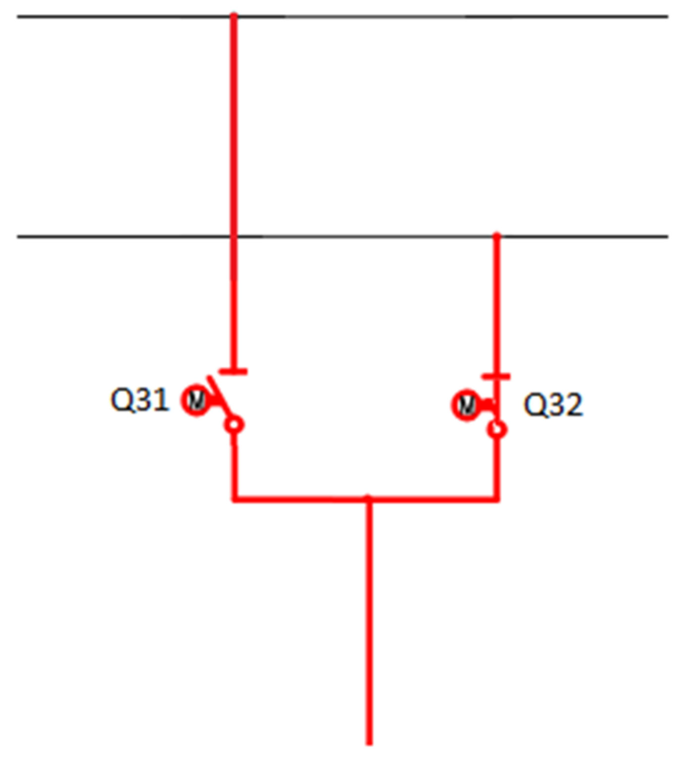
In the simplest words, the methods for depicting the diagrams of large switchgear and their switching methodologies apply to a situation, which assumes that such switching takes place in a single cycle. It has its advantages, since selected (“intentionally”) commutations do not have to lead to system (or its fragment) stability deterioration [2,3]. Step-by-step switching takes plenty of time, which is why it is better if it is automatic with the shortest possible duration and within a single cycle (if possible). An example of such switching can be the situation presented in Figure 1.

Figure 1.
Method of connecting a feeder bay to busbar systems through Q31 and Q32 switches; Q31 is the switch connecting the field to the first busbar system, and Q32 is the switch connecting the field to the second busbar system.
Assuming that switching requires a bay, shown in the figure, to be switched into a second bus system (currently in the first), one can close switch Q32 (if it is not forbidden) and then open Q31 (if this does not result in a power outage). For the sake of simplicity, one can assume that switch Q31 opens and Q32 closes at the same time. If these switching actions are permitted by the station layout and the station operating instructions, it is safe for the system and does not cause interruption to the power supply. Since, with the development of switch-making technology, the response time to the switching impulse and to the switching off impulse decreases and the signals are transmitted with a minimum delay, the time span of the commutation processes is omitted for simplicity in the considerations discussed. This makes it possible—to a certain extent—to shift the emphasis from the dangers carried by the electromechanical stability considerations, namely, voltage stability, to take advantage of practically immediately available current signals and the advantages of almost no excitation of voltage variation (module, argument) at the site of the created break. Furthermore, “breaking” high flows should be avoided when switching. It is only permitted for low flows within a power substation.
The condition of power switches connecting a bay with a busbar system can be treated in a binary manner as a vector, which should contain independent binary variables. For example, as shown in Figure 1, the substation feeder bay switches can connect a node with the first or second busbar system, but not with both simultaneously. In addition, the dynamic nature of each of those control variables can be taken into account.
A binary approach that can be employed when modelling the operating state of a power substation is taking into account (or full depiction) of the base switch state (I) using binary values 0 or 1, as well as their post-switching states (II). They can be depicted in tabular form or using a switch tree (optimization approach). This enables all combinations of switch states to be obtained within a power substation.
Another method for a binary depiction of a power system operating state involves using coincidence matrices within each substation and the entire system. The matrix equation is shown as a relationship (1):
where A is the matrix of coincidence between nodes and branches within a given substation (system), α is the state matrix of switches in individual branches written in a binary manner [0, 1], and Y is the branch admittance matrix.
A × α ⋅ Y ⋅ A−1
The advantage of the binary approach is that it can be employed in algorithms associated with artificial intelligence (as one of the choices—genetic algorithms). By applying a criterion function, for example, for the lowest flow at the point of system division, one can obtain an appropriate switch configuration in a relatively short time. However, this approach also includes a possibility of providing many good solutions (enabling one to choose the best one based on the “superior” criterion).
For the purpose of this article, a method based on changing the branch impedance values was used, which in some ways replaces binary methods. However, it is rather simplified. Instead of using a binary value of 0 or 1 in the vector describing the position of a given switch, the reactance values for the long line (which is not present in the system) and the very short line, respectively, are included. In the method used, the approximation is that there is no missing or direct connection. It is only necessary to speak of a low-impedance connection (for example when considering a substation connection) or a connection with a high impedance modulus (for an open link or the absence of a branch within a substation). However, this creates artificial connections within the substation, which do not exist in reality, but which the calculation programme can “route” power through as an alternative path.
3. Optimization Methods When Considering a Power System Division
Assuming that a fixed power system operating state is considered, one can find nodes within a system to enable its easy division while maintaining electricity supply continuity. The power flow tracking method can be used for this purpose. They enable a local approach, using paths between the considered areas, rather than an “overall system” approach.
The fact that subsystems will be able to operate independently of each other after an appropriate division arises from the natural power flow between generation nodes and consumers. Each of the nodes enables appropriate control of the power switches (closing individual branches connecting the bays with busbar systems and sections) in order to optimize the power flow path within a single substation.
When analysing the approach, which assumes that power lines and substations are a path between the producer and consumer that implements electricity transmission, one can state that a generating node gives away gross power (energy), and the consumers receive net power. Loss on lines (transmission) is directly related to the specifications of the utilized transmission paths.
The system division process may be implemented employing an optimizing knapsack problem [4,5]. When considering the optimization problem with a set of consumers, one should supply as many of them with electricity as possible. At the same time, the capacities of power lines to transport this energy and the generating capacities of the generation sources within the system should be taken into account. Therefore, assuming that the division will transform one system into two subsystems to operate independently, one can consider a standard knapsack problem, namely, creating a subset of all system elements so that one “knapsack” subsystem fits as many of these as possible. At the same time, one should bear in mind that the system contains sets that require a continuous power supply and should be treated with the highest priority.
Therefore, with n elements in the system, each of which has a pi value (interpreted as power drawn from the system) and a wi weight (which determines their role within the system), and assuming that a specific “knapsack capacity” v is available (generating capacity of the sources installed within the formed subsystem), the optimization problem comes down to finding such an element subset, which satisfies conditions (2) and (3):
where xi is a variable decision [5].
max Σi (pi × xi)
Σi (wi × xi) ≤ v
The decision variable xi within such a formulated problem should be treated as a variable with a binary character {0,1}. This means the presence or absence of a given element in the subsystem created by dividing a power system.
4. Binodalization Procedure
Dividing a large power substation into smaller substations enables commencing switch operation within this substation.
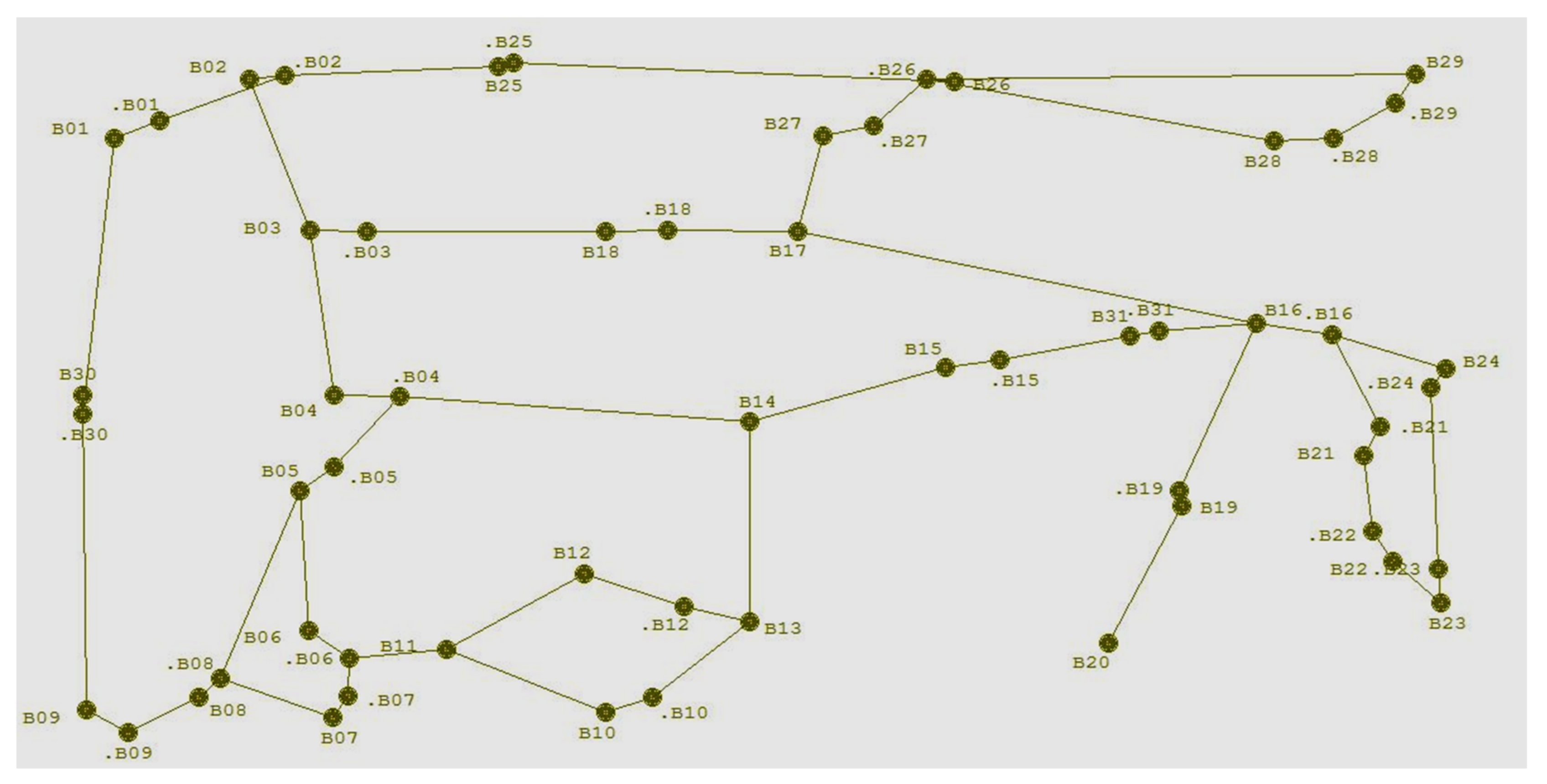
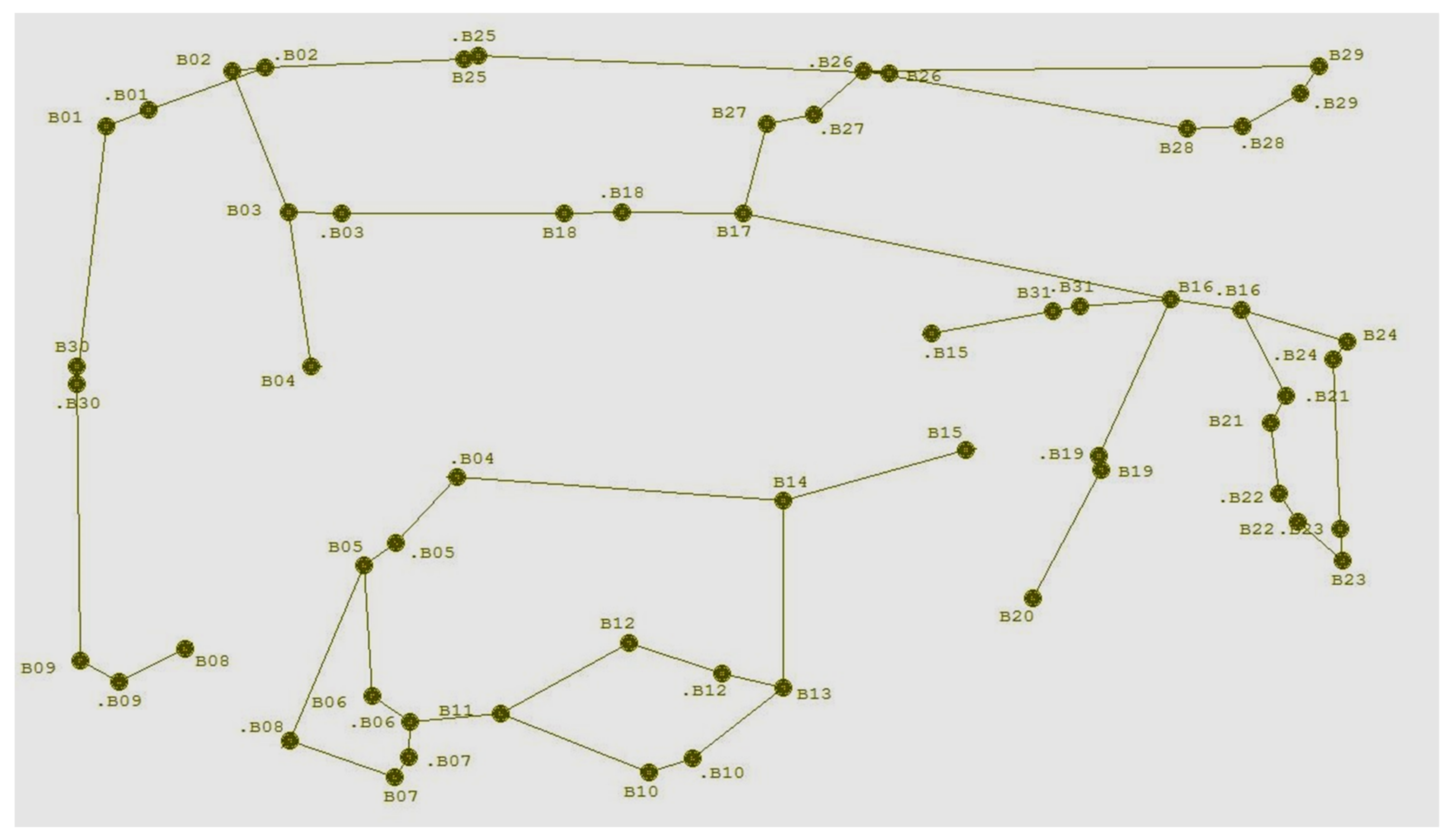
The New England (NE) test system, a modified and simplified version [6,7], with its diagram shown in Figure 2, was employed for the purposes of discussing an example of a process of dividing a power system into subsystems.
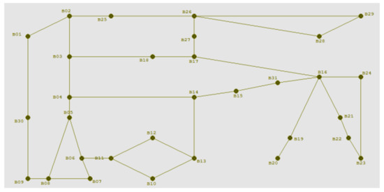
Figure 2.
A sample New England test system.
This system was chosen because it can be treated as a large system (there are quite a large number of nodes in it, several of which are extended substations) in which it is possible to separate several smaller subsystems without changing the parameters of the power sources or loads. In addition to this, it is small enough that a separation can easily be made, which will serve to convey the idea of the method for the purposes of this article. The representation by means of it will be more illustrative than by using a large test system, such as IEEE 118, in which there are many more dependencies between nodes and, for the purposes of the article, it is too extensive (it will be used in a further stage of research work on the topic under discussion).
The selected system contains 31 nodes [7], each being a substation of a certain layout. The system on which the considerations were based is a simplified one used by the authors for teaching purposes. Each of the substations contains outflows (or inflow generations) that are not projected onto the diagram shown in Figure 2 and are only modelled within the system in the software. Each generation was simulated as an appropriate mathematical model for the generator set, together with an algorithm for its adaptation to grid conditions, including the excitation systems of the synchronous generator. This was applied directly in the calculation program. Lines and loads were also created via appropriate mathematical models of these power system components.
Power substations that constitute stable operation elements (transmitting large-span flows) are of a highly expanded structure, ensuring correct EPS (electrical power substation) operation and low-risk electricity supply to consumers. Such large facilities, for imaging purposes, can be divided into two smaller substations, each of which will have its own consumer, and a low-impedance connection between them. This is the so-called binodalization procedure [8].
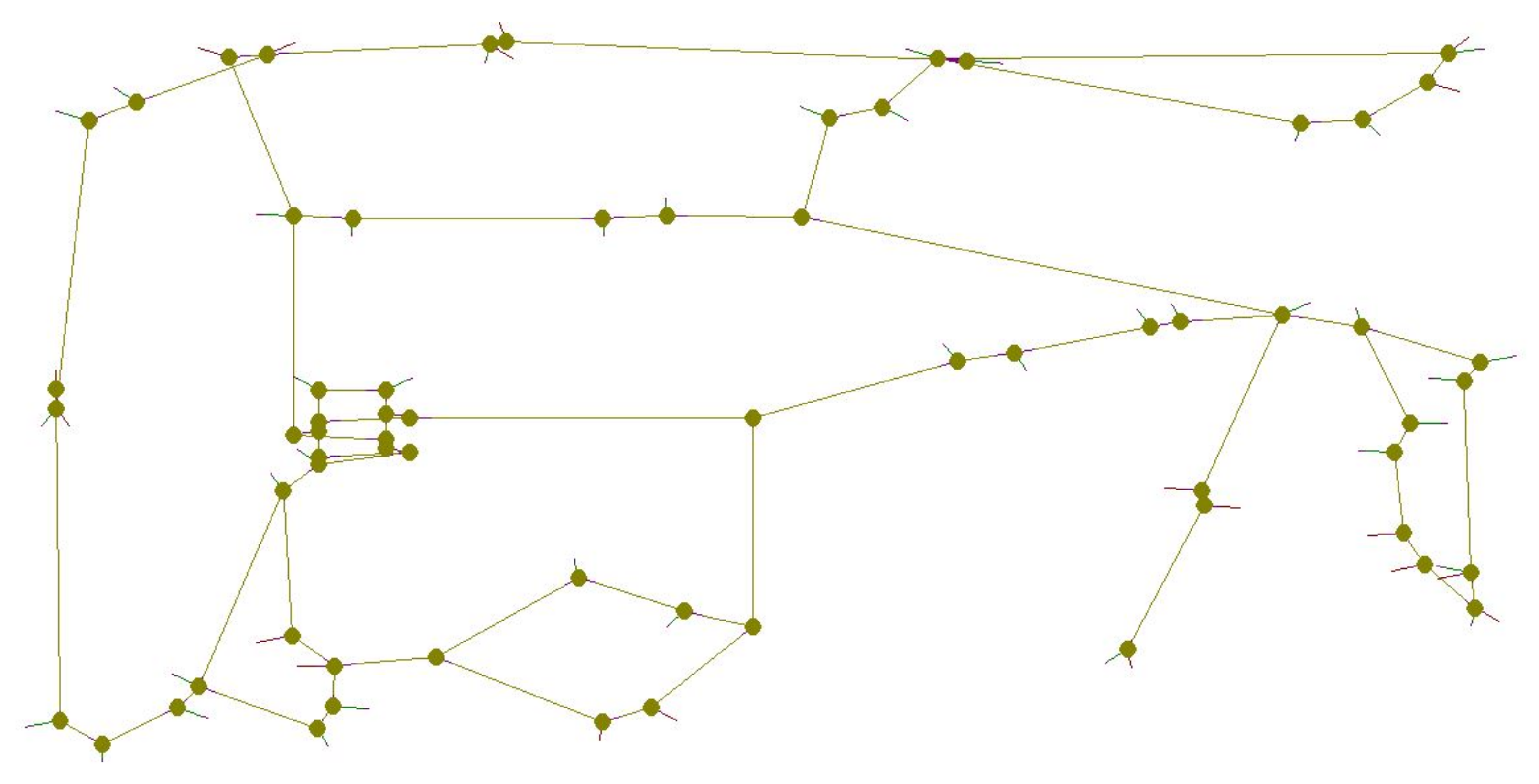
The binodalization process within the presented NE system may look as demonstrated in Figure 3.
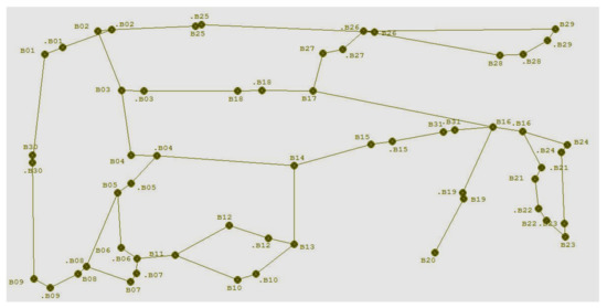
Figure 3.
Binodalization process demonstrated on an NE test example: a modified and simplified version.
Binodalisation makes it possible to represent a substation as two substations connected by a power coupling issued to open in order to separate the subsystem (with power flow control). It is a way of representing the system to the master system without having to penetrate the structures of each substation, giving the possibility of only sending the command “off” to the switch, selected in the process of the substation systems.
The system nodes in Figure 3 are marked as Bx and .Bx. This means that the general Bx node was divided into two, with one maintaining the previous name and the name of the other one expanded with a dot (in front of the name).
Such an approach enables power (energy) flow analyses and the possibility to divide the system without going deep into the substation structure, since the I&C of the substation will provide follow-up selection (“suggest” for potential application) of the branch switch, e.g., B-.B, and without the need for divisions within the substation, which would be complicated during modelling.
At the same time, as mentioned above, the division of nodes into two also caused a division of outflows and inflows, which are not plotted on the diagram shown in Figure 3.
5. Switching with the Power Substation
As mentioned previously, each of the substations has its own structure. An example of a B04 substation bay layout is one with a double busbar system, as shown in Figure 4.
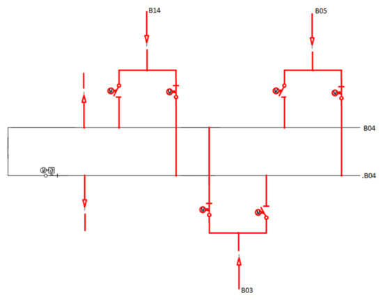
Figure 4.
B04 station structure.
It is one of the basic, typical busbar layouts in an HV power substation. It enables uninterrupted power switching within a power substation and ensures consumer supply reliability. Feeder bays (Power system PL) usually have two system isolators and one breaker. However, there are sometimes two breakers in a bay. Such a system is applied in 400 kV substations. The normal operating state is when both systems are energized, and both breakers are active. A failure of one of the systems leads to the deactivation of its connected breakers, which enables facilitation of the operation, substation operational flexibility and increased operational reliability. This variant does not involve the need to manipulate the isolators, which additionally mitigates the possibility of making a switching error. Other substation systems have been reviewed in the literature (e.g., [9]).
Each of the bays in the case in question is connected to one of the systems, and the system switching device remains closed. The lines between nodes B04 and B03, and B05 and B14 are substation power feed lines. Such a substation can be easily subjected to binodalization. It is sufficient to correctly connect the feeder bays to a selected busbar system (or leave the existing connection) and open the system switch. This approach allows a substation to be viewed as simply divisible into two substations, each of which can have different configurations. Using this way of subdividing a substation provides a simpler way of looking at intra-station divisions, as described later in this article.
The main criterion for selecting a node to be divided is the fact that minor power flows through the lines connecting them during the binodalization process (Figure 3).
Therefore, the B04 node can be divided into two subnodes, as in Figure 3. One of the nodes will be marked as B04, and the other as .B04. In the present case (where there are two busbar systems), the name of the substation is equivalent to the name of the busbar system concerned. This view makes it possible to subdivide the substation by appropriately attaching individual bays to the busbar system (or, in another case, for example, to the corresponding section separated by a section link).
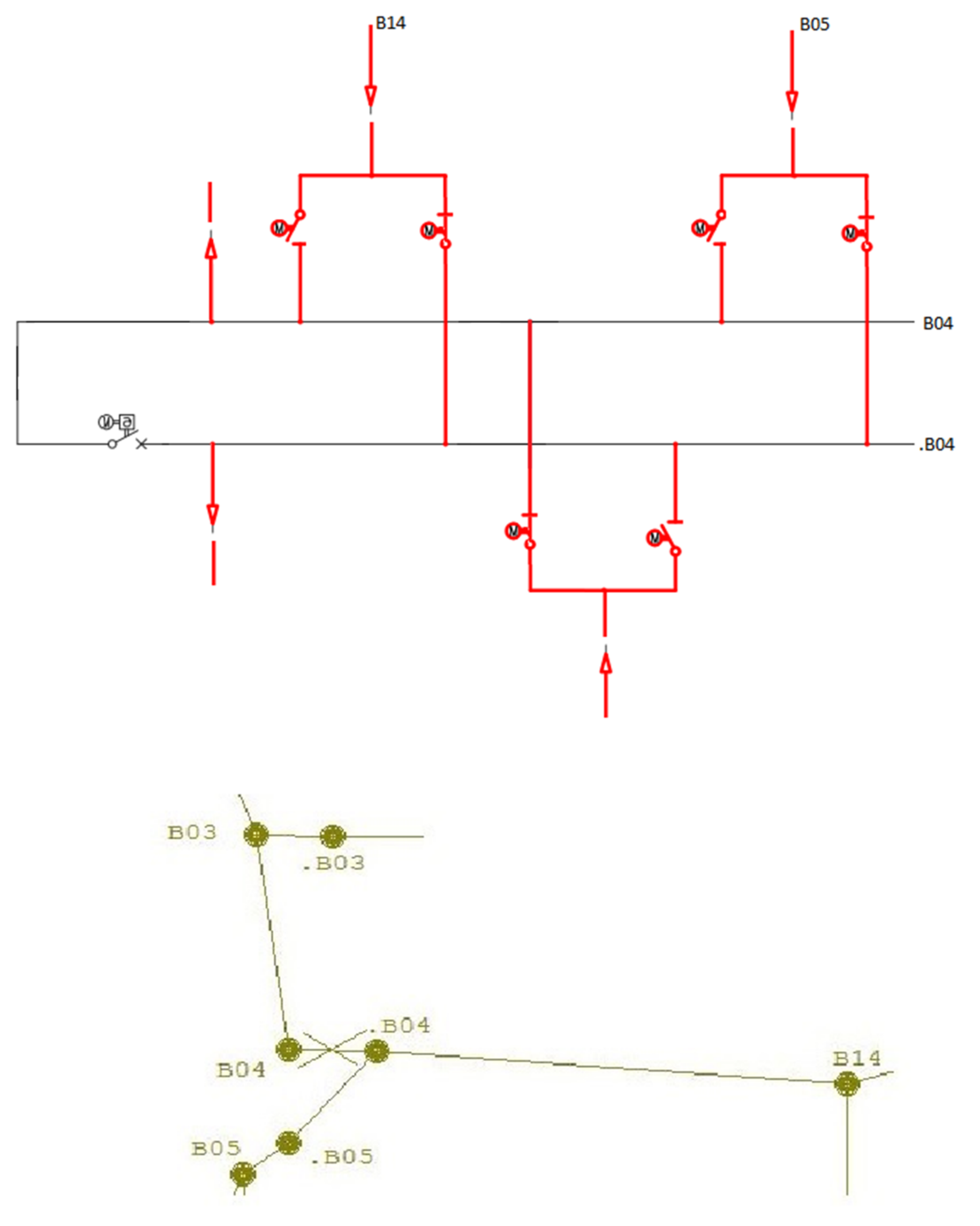
Figure 5 shows a structure of the NE test system fragment with a drawn B04 substation busbar layout (in a more general case, it may be the suitably simplified equivalent of the internal connections of a station), shown in Figure 4.
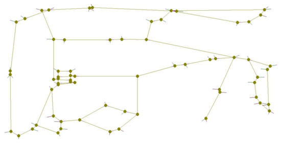
Figure 5.
Structure of the NE test system fragment with a drawn B04 substation busbar layout.
This Figure takes into account the branches with an open switch. They were created for computational purposes and in order to switch at a later time.
The switch position within a given bay was reflected by assigning a relevant (artificial) impedance (longitudinal)—according to the variable branch impedance method used. It has a high value for open switches, corresponding to longitudinal reactance, created by a line about 200 km long (400 kV). In the case of closed switches, a several-kilometre line impedance was adopted (for computational reasons, typical software does not allow zero branch impedance values). This approach makes it possible to simulate the states of operation of the switches in a given station (during switching, the impedance of the branch in which the switch has been moved changes), while at the same time maintaining (for the sake of the capabilities of the calculation program) the continuity of the branch in question. This is because the impedance is very high (it represents an undoubted break in such a small circuit), but nevertheless exists as a certain calculation value in the admittance matrix.
6. Aforementioned Example of a Power System Division
Figure 6, as previously stated, shows a B04 substation division into two smaller substations. The division was conducted by changing the states of the switches connecting the bays with busbar systems. One of the systems was connected with lines from the B14 and B05 substations (.B05 more precisely), and the second system was supplemented with a line connecting the B04 node with the B03 node. In addition to these three fields, the substation also has two outflow fields, consuming around 200 MW and 300 MW, where the switches will not change states.
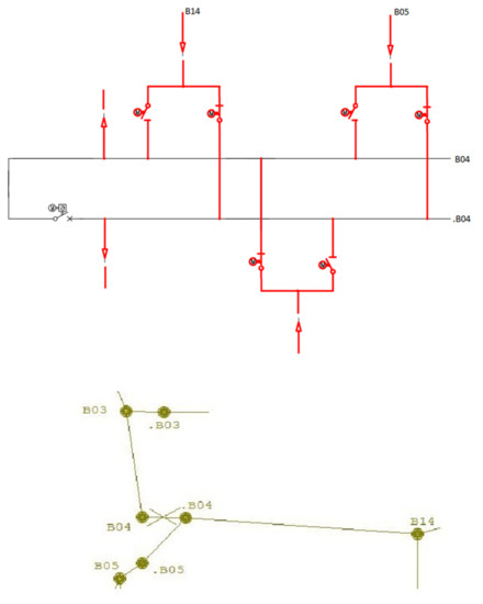
Figure 6.
B04 station division into two substations.
The system switch has been opened. As a result, two substations were formed:
- First one: defined as a busbar system I marked with B04;
- Second one: defined as a busbar system II and marked with B04.
Similar to B04, the B15 and B08 nodes have their own structure.
Therefore, assuming that they have the same busbar system as the B04 substation, it is easy to divide them (similarly to B04). Ultimately, as per Figure 3:
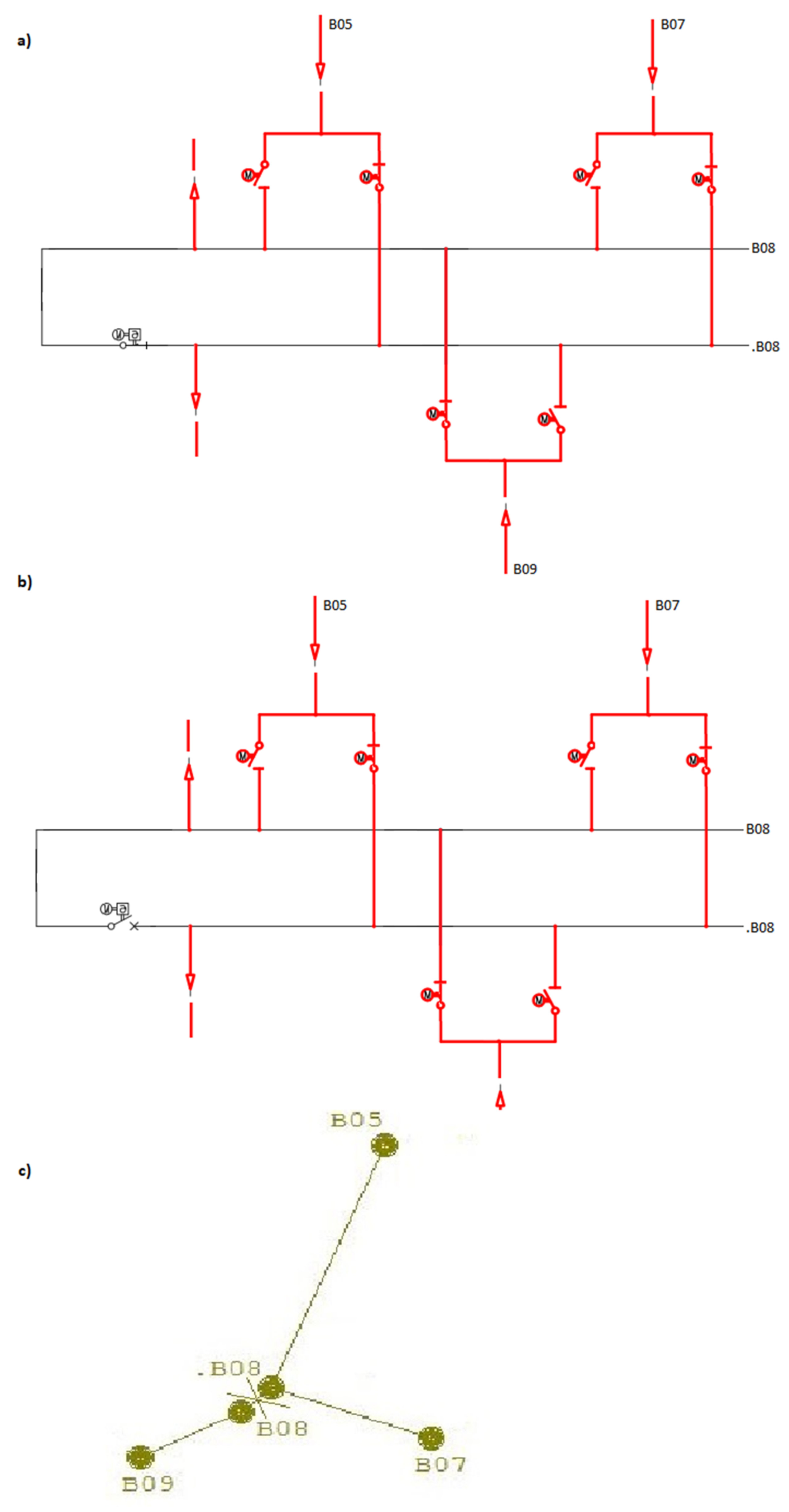
- The B08 node was divided into two substations, namely, B08 and .B08, as per Figure 7. The division was conducted by opening a switch in the system switching device. At substation B08, in addition to the three fields involved in the switchover, there are two outflow fields consuming around 100 MW and 420 MW. However, their switches will not change states;
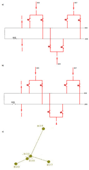 Figure 7. B08 station busbar system (a) prior to division into substations and (b) after the division; (c) connection in the system after the division at node B08.
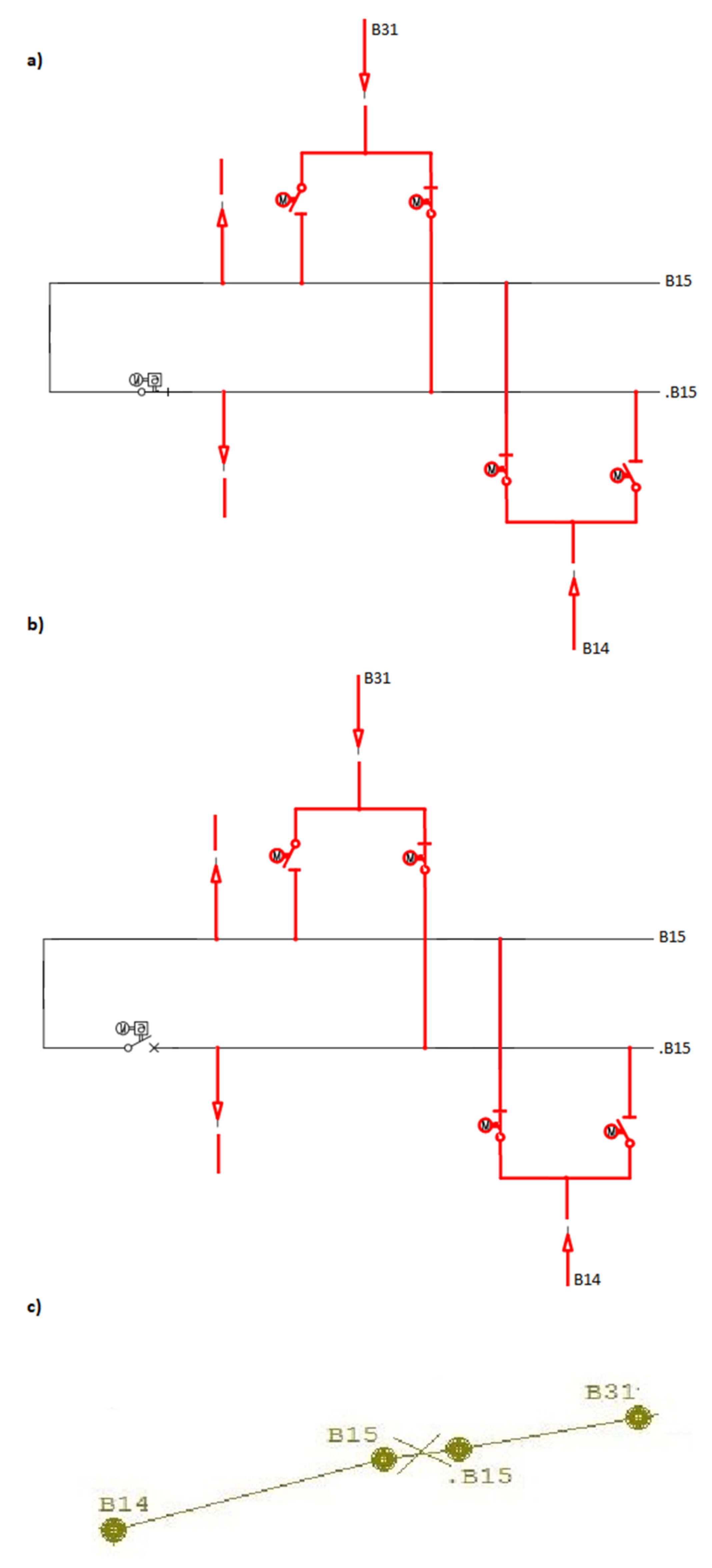
 - The B15 node was divided into B15 and .B15 substations, as shown in Figure 8. Similar to the previous substation, the division was conducted by opening a switch in the system switching device. At substation B15, in addition to the two fields involved in the switchover, there are two outflow fields consuming around 120 MW and 200 MW. However, their switches will not change states.
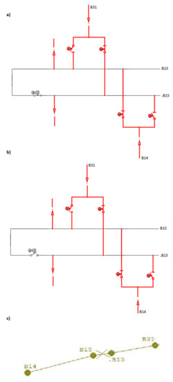 Figure 8. B15 station busbar system (a) prior to division into substations and (b) after the division; (c) connection in the system after the division at node B15.
7. Strategy in a Binodal Approach (from the Perspective of the Power System), Combined with the Need to Take into Account Intra-Station Commutation—The Use (in Calculation Terms) of Artificial Transformer Sets with Combined Transmission
Binodalisation (presented earlier) may indicate the location of a possible separation, but this is a level that must be correlated with the technical possibilities of physically carrying out the necessary commutation at the indicated (selected) substations. In each substation, there is a list of critical technical constraints (numerically reaching tens or even hundreds) that must be taken into account. An example of an unauthorised switching within a substation would be when there are two supplies (primary and reserve) for one load in one substation. It will then be forbidden to switch both supplies to one busbar system. Other critical technical constraints are (or should be) included in the substation operating instruction. These constraints are technical constraints and therefore related to the construction and operation of substations and the loads they supply.
An approach will be presented in which a sequence of artificial (quasistationary) commutations will be subject to modelling using transformer models with composite transmission [10]. This will be modelled in (mainly artificial) complexes interacting with branch (active) powers P via a transverse gear setting (PST phase shift) [1,11,12].
When creating lists of possible binodalisations in large substations, it is necessary to penetrate the structure of each substation, as the final division of the substation into two nodes will be made by a circuit breaker implementing a branch break where the power P is sufficiently small.
There are great advantages in a method that assumes that the switches in the station are branches whose power can be tuned, and therefore there is no need to take switch states, which is limited by certain restrictions.
For editorial reasons (and the associated need to weigh up the emphasis), the idea of this approach will be illustrated with a focus on the case of the subdivision of the B04 substation (the first of the three previously addressed).
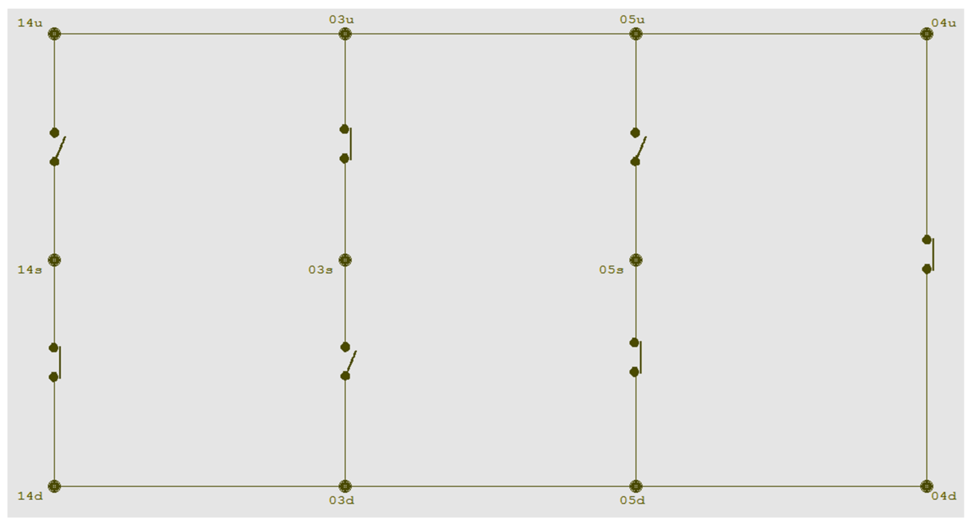
Station B04 can be divided into two nodes, namely, B04 and .B04. Figure 4 shows a diagram of the substation and the positions (states) of the circuit breakers before the possible division of the substation into two sub-nodes. The operating state of the substation before splitting can be represented in an alternative convention of using a diagram, for example as in Figure 9 (several nodes and branches).
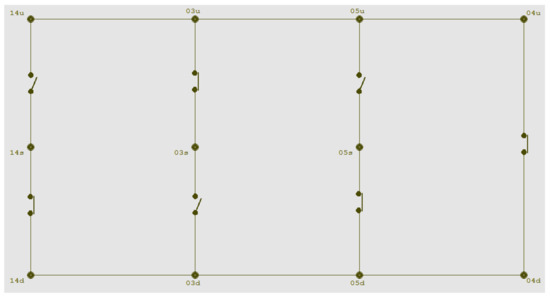
Figure 9.
Diagram of the operating status of station B04 before subdivision.
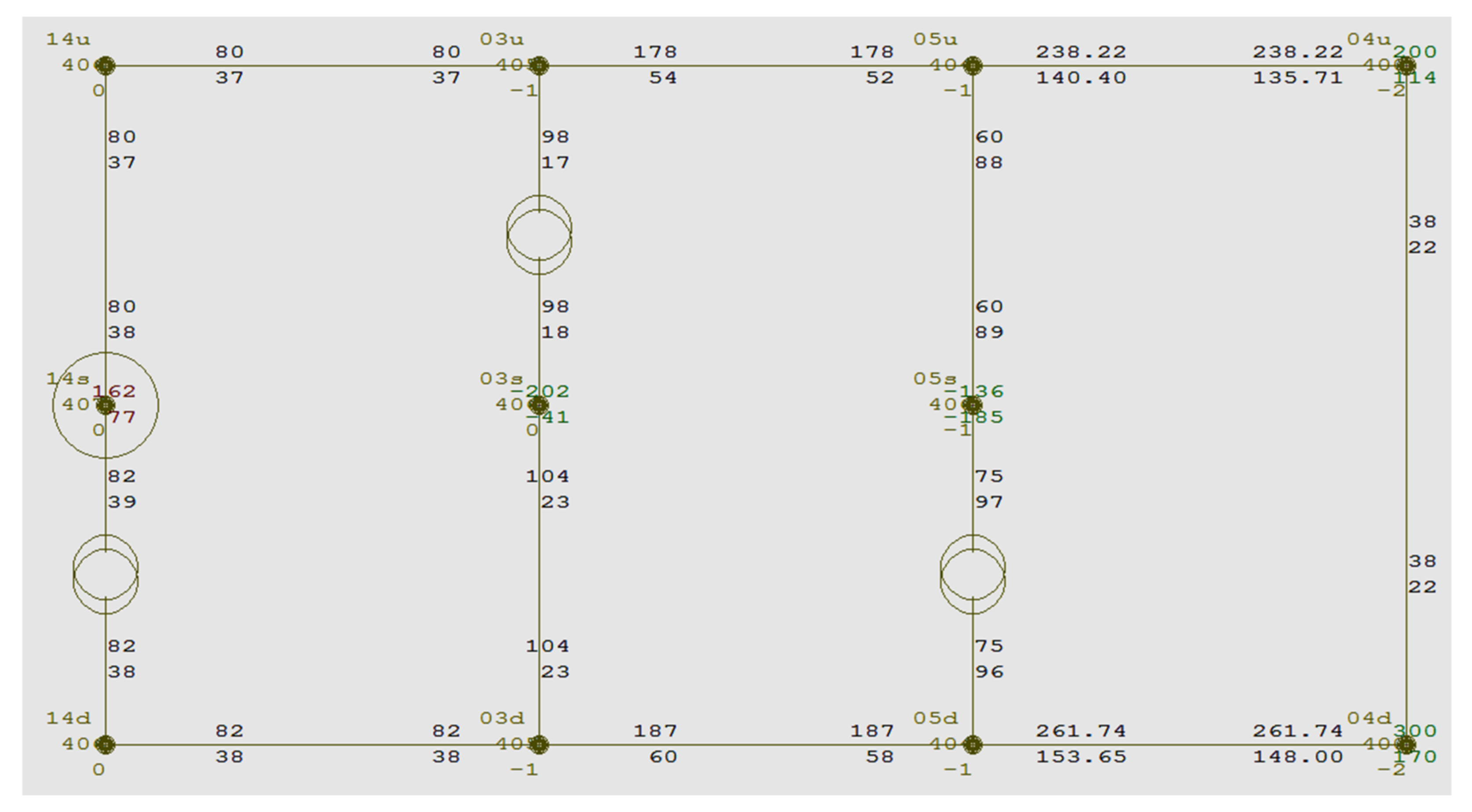
It is possible to interact with the intra-station flows using such an extremely simplified diagram, enriched with three artificial transformers with composite transmission, as shown in Figure 10. It is then also possible to artificially assume that all circuit breakers are in the conducting state (are switched on).
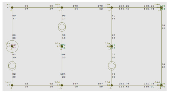
Figure 10.
Diagram of the operating status of substation B04 before subdivision enhanced with artificial transformers with composite transmission.
In fact, circuits such as those in Figure 9 and Figure 10 can be equivalent to the actual primary circuits of the substation, with details enriched as required, or with details subject to reduction (for example, two radial, 200 MW and 300 MW, energy discharges from the substation located near the upper and lower busbar system connector fields).
In the presented procedure, the branch impedances of the busbar sections of the substation, but also the internal impedances of the circuit breakers in the closed state, can be mapped, for example, by means of an approximate, small, unified along impedance, , the reactance of which can (in the limit) aim at an approximate real value. In the issue described, there is no need for this.
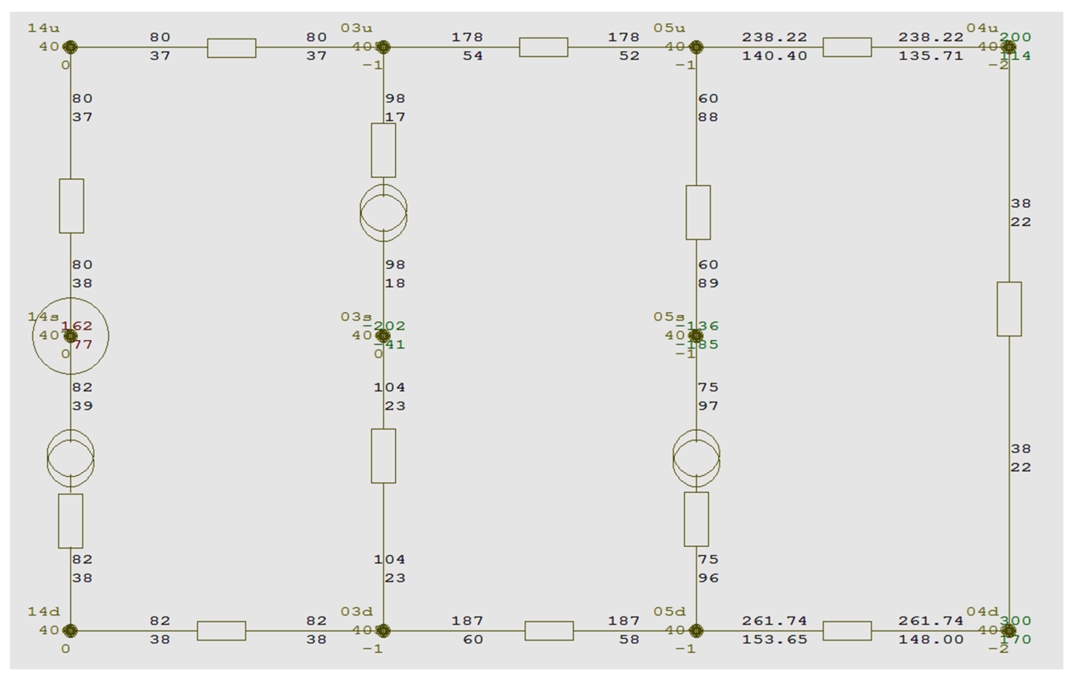
In series with these longitudinal impedances—at selected branches of the connectors—ideal transformers with composite transmission are located in the mesh, as shown in Figure 11. These must be controllable (independent) gears. In the example described, they are located quite arbitrarily (but at the location of one of the two connectors of each transmission line). The diagram must be consistent and the connectors conductive (closed).
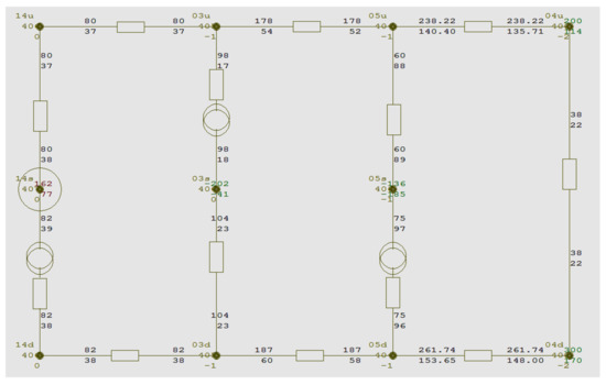
Figure 11.
Schematic of the operating state of substation B04 before subdivision enriched with artificial transformers with composite transmission and along branch impedances.
The composite transmission of artificial PST complexes can be simplified to a form , in which no longitudinal gears are controlled. These are artificial creations. In fact, transformer assemblies are built (for use in the system), which can consist of several specific transformers. The artificial transformer unit described here has a functionality similar to that of laboratory-applied phase shifters (3 poles of stator and 3 poles—stopped and adjustable, e.g., via worm gear—of the rotor). Phase shifts can also be used as a substitute for phase shift increments (since each is zero at the initial moment).
The vector of controls is, therefore, as follows:
while the vector of independent variables includes the following branch active power increments:
Using the classical approach—commonly used in the analysis of qua steady-state operation of transmission networks—a sensitivity matrix of branch active power increments to PST phase shift increments is obtained [13]. This matrix () occurs in relation (6)
In the example described, it is as follows (active capacities in relative units relative to a base power of 100 MW, phase shift settings in radians):
Thus, by selecting the phase shifts of the three PSTs mentioned above, it is possible to determine the branch powers based on the branch powers at the point of expansion , increased by the increment caused by the selection of the phase shifts :
Relationship (8) is a component of the matrices and vectors presented earlier.
At stations B04 and .B04, the binodalisation approach indicated that a flow of approximately 2.5 MW could be interrupted. The algorithm based on the above equation will select the upstream and downstream coupler of the rail system as critical (for possible flow interruption). The linear couplers will retain the states as initially shown in Figure 9.
The following advantages of using algorithms of this type can be pointed out:
- They can make the above calculations on an ongoing basis (and locally) so that the optimum distribution of stations has a prepared basis,
- The optimisation algorithm operates with a whole set of technical constraints—as a result, the signal of a possible split will not be a challenge to the station, which would override the idea of optimal division,
- The optimisation algorithm can easily operate on natural constraints, for example, in the row series of the sensitivity matrix shown above, there are coefficients that naturally direct the flow in the line towards one of the linear connectors (at the expense of the other—this flow will correspond to the flow in the line),
- Individual connectors (groups of connectors) can be assigned weighting factors, so that the critical connector is the most appropriate one for these purposes,
- If the division does not take place in a single cycle, the optimisation algorithm may have the function of indicating a secondary compromise solution.
In the example shown of sub-system separation, two more stations are also subdivided. If a split is made allowing for higher interruptible flows, this should involve either the need to switch off some sources (to avoid, for example, a temporary increase in frequency) or the need to switch off some loads (to avoid, for example, a temporary decrease in frequency). This could be considered in more detail in the optimisation algorithm.
In the subdivision optimisation problem presented, passive capacities (Q-flows) are assumed to be of secondary importance. In areas of the network where problems with these flows could be critical, this can be taken into account by increasing the weighting of the associated coefficients in the optimisation algorithm. The reactive power and nodal voltage signals, as well as the more locally placed mathematical models of the operating states and their expected dynamics of change, can be used to elicit a positive or negative signal from the station system and influence the main signal (whether or not division is allowed in that station).
After switching the line, following the statements above, one can observe that low power will flow through the system switches. This is shown in Figure 12, Figure 13 and Figure 14. These figures show the power (energy) flow in system switches of these stations in closed states, as well as power flows within their areas.
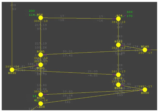
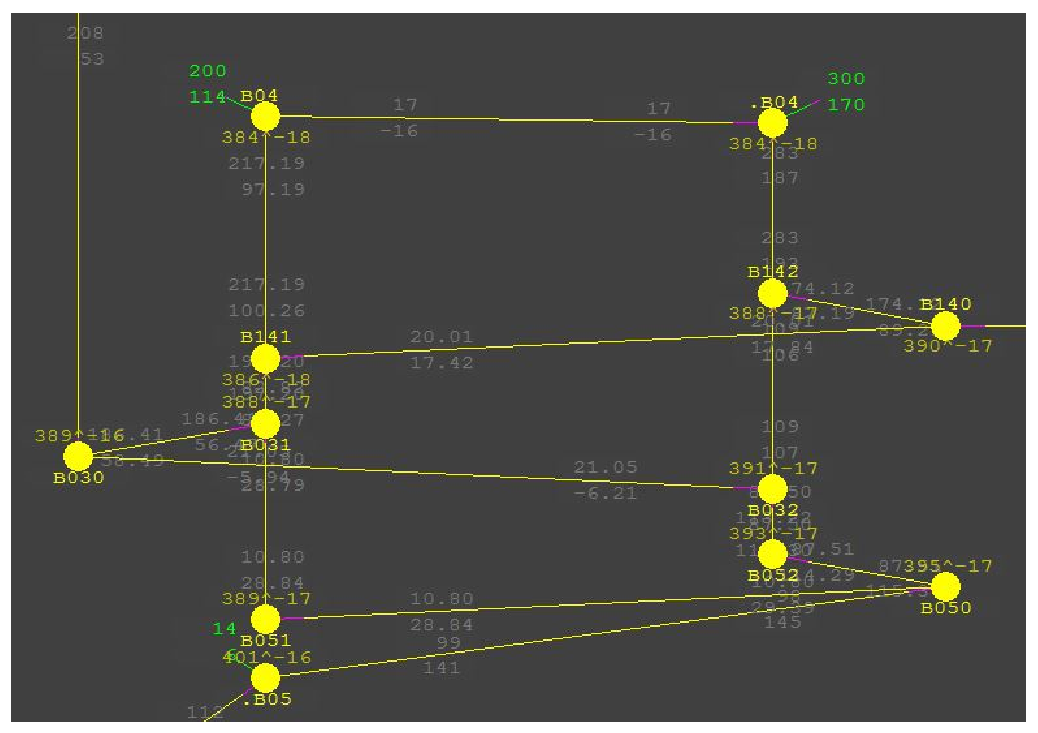
Figure 12.
Mosaic of flows against the complex interconnection system equivalent of the primary circuit structure of station B04. The green markings represent power consumption, the red markings represent power generated, the violet colour indicates the direction of the return of the flow arrow and the white markings represent line power flow. The other designations are node symbols (they are not relevant).
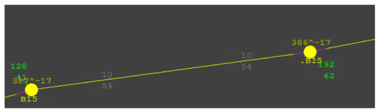
Figure 13.
Power flows in the B15 substation prior to opening the system switch. The green markings represent power consumption, the red markings represent power generated, and the black markings represent line power flow. The other designations are node symbols (they are not relevant).
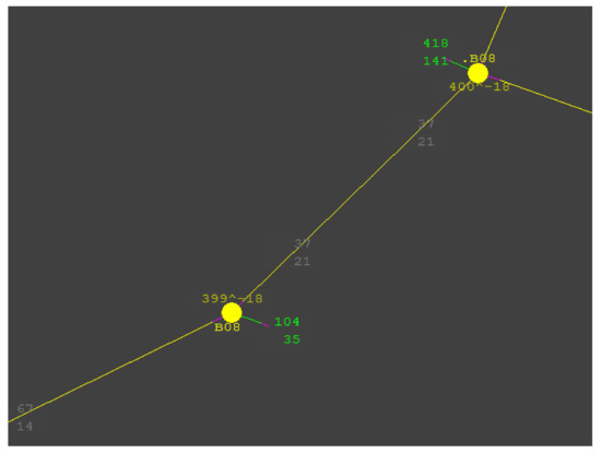
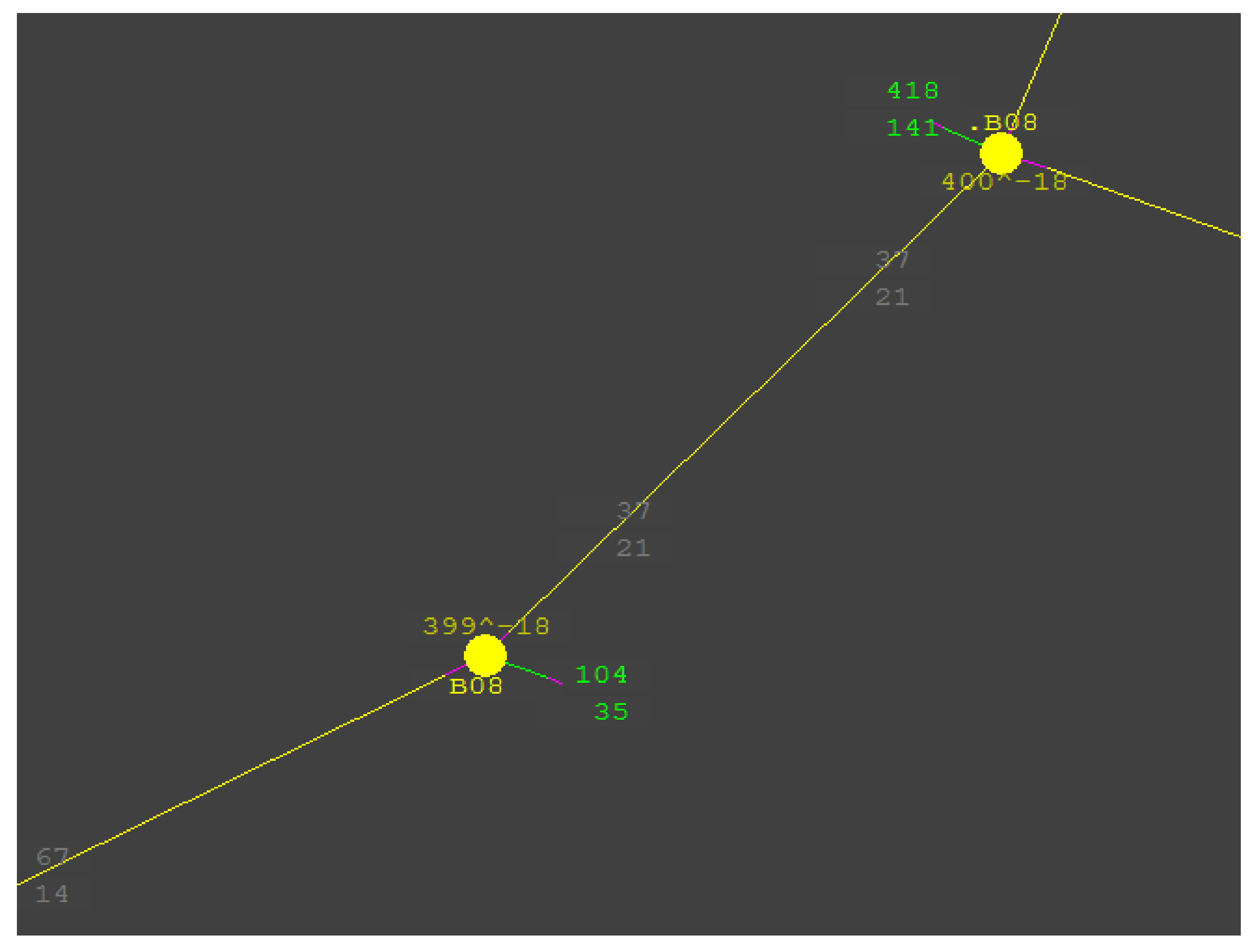
Figure 14.
Power flows in the .B08 substation prior to opening the system switch. The green markings represent power consumption, the red markings represent power generated, and the black markings represent line power flow. The other designations are node symbols (they are not relevant).
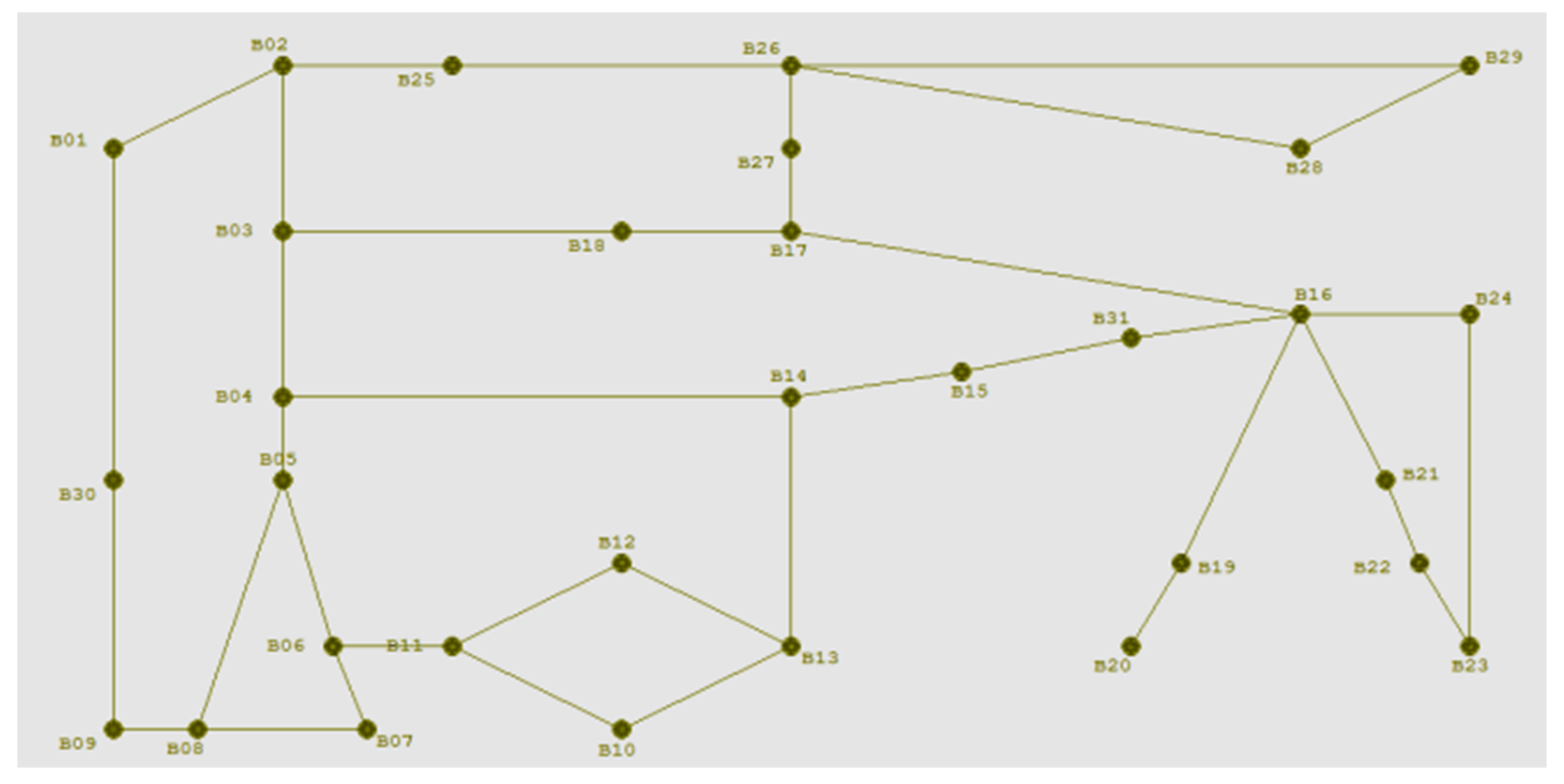
Low-power flow in system switches means that opening the switching devices will not cause detriment to the operation of the entire system, and an “island” can be successfully separated through divisions in stations B08, B15 and B04. The island can operate independently. Figure 15 shows a test system fragment with a separate island.
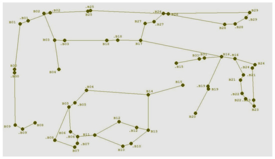
Figure 15.
Subsystem separated after commutation processes.
Two subsystems were established after the division of the B08, B04 and B15 substations. The employed simulation software enabled conducting computations, which is why the created island is balanced and can operate regardless of the rest of the system.
The power flow in individual system branches also changed. The powers flowing in the flows changed slightly.
In total, the power flowing into the unbundled subsystem will decrease. In contrast, there will be excess capacity in the other subsystem. While it does not seem problematic if there is too much power in the system, as the generation of some (or all) of the power plants can be easily reduced, increasing the power in the isolated island requires more treatment. Where possible, the power generated at local power plants can be increased. If power reserves are available, this will be the easiest way to make up the power deficit. If, on the other hand, such a technical measure is not possible, the power demand should be calculated within an isolated island. This is done by disconnecting consumers whose supply is not a priority or by reducing the demand in individual consumers while keeping them in operation. For example, one of the production lines in a plant may be shut down. Such actions may not be satisfactory for energy consumers but will help to maintain the subsystem independently of the rest of the system.
A stumbling block may be the excessive, difficult-to-control dynamism of the operating states of such a dedicated radial area, resulting, for example, in insufficient generation associated with the need to control local sources (e.g., renewable energy sources) or difficulties in maintaining the right frequency. In the short term, however, such a sub-system could operate relying on a rapid reconnection to a central part of the system with conditions for continuous operation [14,15,16,17,18,19,20,21].
8. Summary and Conclusions
Binodalization is a process that facilitates dividing a system into subsystems. Knowing the substation busbar layout and values describing inter-station links, one can easily adapt the method of connecting individual bays to sections or a system. Optimization methods, such as the mentioned description of the knapsack problem or the flow tracking method, can help in achieving this.
Power switch states can be described using binary notation or, as in the case of the simulation herein, a variable branch impedance value. Although the second method is similar, it provides expected results and enables computations to be conducted.
The article discusses examples of the commutation process design in power substations that can be helpful when intentionally dividing a power system into subsystems. They can be also beneficial for people dealing with power transmission planning in a power transmission system. The material presented in this paper demonstrates that it is possible to carry out switching within a substation without affecting the operation of the power system (its stability and correctness of operation). In addition, it is possible to separate a subsystem as a result of previously performed substation switching and the selection of a suitable switch performing the separation operation. In this way, two subsystems are created, each of which is balanced, and the separation has been controlled. This makes it possible to argue that an intentional power system splitting scenario is possible and can be used by transmission system operators.
The process of binodalization, as presented, serves the possibility of looking at the power system from the perspective of the host system (system operator) without having to penetrate the substation structure. It simplifies the way in which subsystems are separated to issue the "open" command to the switch selected by the substation automation. This simplifies both the calculations performed in the host system and allows a list of possible separation scenarios to be created.
The goal of searching for variants in dividing a system into subsystems is the possibility of such a change in power substation connections that would enable the counteracting of the consequences of potential system failures, which could disrupt its normal operation.
From the point of view of the paper’s authors, it is an issue that is important and requires advanced research from the perspective of the power network and system development and in light of progressing changes.
Author Contributions
Conceptualization: A.S., S.Z.; methodology: A.S. and S.Z.; software: S.Z.; validation: A.S., S.Z. and M.S.; formal analysis: A.S.; investigation: A.S. and S.Z.; resources: A.S. and S.Z.; data curation: A.S., S.Z. and M.S.; writing—original draft preparation: A.S.; writing—review and editing: A.S., S.Z. and M.S.; visualization: A.S.; supervision: S.Z. and M.S.; funding acquisition: M.S. All authors have read and agreed to the published version of the manuscript.
Funding
This work was financed by the Military University of Technology under research project UGB 737/2022.
Data Availability Statement
Not applicable.
Conflicts of Interest
The authors declare no conflict of interest.
References
- Ziemianek, S. Tracking Power Flows in Electricity Grids as a Mechanism on the Evolution of the Power System Description; OWPW: Warsaw, Poland, 2013. (In Polish) [Google Scholar]
- Kundur, P.; Paserba, J.; Vitet, S. Overview on definition and classification of power system stability. In Proceedings of the CIGRE/IEEE PES International Symposium Quality and Security of Electric Power Delivery Systems, Montreal, QC, Canada, 8–10 October 2003. [Google Scholar]
- Machowski, J.; Białek, J.; Bumby, J. Power System Dynamics, Stability and Control; John Wiley & Sons: Chichester, NY, USA, 2009. [Google Scholar]
- Sapra, D.; Sharma, R.; Agarwal, A.P. Comparative study of metaheuristic algorithms using Knapsack Problem. In Proceedings of the 2017 7th International Conference on Cloud Computing, Data Science & Engineering-Confluence, Noida, India, 12–13 January 2017. [Google Scholar]
- Łyczek, M. Metoda Podziału i Ograniczeń; Seminarium, Algorytmy heurystyczne: Warsaw, Poland, 2011. [Google Scholar]
- Henderson, M.; Rappold, E.; Feltes, J.; Grande-Moran, C.; Durbak, D.; Bileya, O. Addressing restoration issues for the ISO New England system. In Proceedings of the 2012 IEEE Power and Energy Society General Meeting, San Diego, CA, USA, 22–26 July 2012. [Google Scholar]
- NGC. Seven Year Statement, (1999/00-2005/06); National Grid Co.: Coventry, UK, 1999. [Google Scholar]
- Ziemianek, S. Research and Test Calculations and Development of Conclusions and Recommendations for a Methodology for Pre-Emptive, Automatic Subdivision in a Meshed Transmission Network in the Presence of Threats of Imminent, Uncontrolled Loss of System Integrity; PBZ-MEiN-1/2/2006; IE PW: Warsaw, Poland, 2009. (In Polish) [Google Scholar]
- Dołęga, W. Electrical Substation; Oficyna Wydawnicza Politechniki Wrocławskiej: Warsaw, Poland, 2007. (In Polish) [Google Scholar]
- Ziemianek, S. Mathematical models of some phase shifting transformers for power system analyses. In Proceedings of the International Symposes “Hoflerov Days”, Portoroż, Slovenia, November 2005. [Google Scholar]
- Ziemianek, S. Methods for Tracking Flows in Electricity Networks as Applied to Technical and Economic Analyses; OWPW: Warsaw, Poland, 2008. (In Polish) [Google Scholar]
- Mustafa, M.W.; Shareef, H. A comparison of electric power tracing methods used in deregulated power systems. In Proceedings of the 2006 IEEE International Power and Energy Conference, Putra Jaya, Malaysia, 28–29 November 2009. [Google Scholar]
- Ziemianek, S. Steady States in Power Systems; OWPW: Warsaw, Poland, 2014. (In Polish) [Google Scholar]
- Wang, M.; Higa, S.; Yona, A.; Senjyu, T. Optimal Operation of Power Systems with Power Players; Department of Electrical and Electronics Engineering, Faculty of Engineering, University of the Ryukyus: Okinawa, Japan, 2012. [Google Scholar]
- Huang, K.; Srivastava, S.; Cartes, D.; Sloderbeck, M. Intelligent agents applied to reconfiguration of mesh structured power system. In Proceedings of the 2007 1st Annual IEEE Systems Conference, Kaohsiung, Taiwan, 5–8 November 2007. [Google Scholar]
- Bulter, K.L.; Sarma, N.D.R. A new method of network reconfiguration for service restoration in shipboard power systems. In Proceedings of the 1999 IEEE Power System Society Transmission and Distribution Conference, New Orleans, LA, USA, 11–16 April 1999; pp. 11–16. [Google Scholar]
- Xiaodan, Y.; Hongjie, J.; Chengshan, W.; Wei, W.; Yuan, Z.; Jinli, Z. Network reconfiguration for distribution system with micro-grids. In Proceedings of the 2009 International Conference on Sustainable Power Generation and Supply, Nanjing, China, 6–7 April 2009. [Google Scholar]
- Solanki, J.M.; Schulz, N.N. Using intelligent multi-agent systems for shipboard power systems reconfiguration. In Proceedings of the 13th International Conference on Intelligent Systems Application to Power Systems, Arlington, VA, USA, 6–10 November 2005. [Google Scholar]
- El-werfelli, M.; Dunn, R.; Iravani, P. Backbone-network reconfiguration for power system restoration using genetic algorithm and expert system. In Proceedings of the 2009 International Conference on Sustainable Power Generation and Supply, Nanjing, China, 6–7 April 2009. [Google Scholar]
- Mahela, O.P.; Khosravy, M.; Gupta, N.; Khan, B.; Alhelou, H.H.; Mahla, R.; Patel, N.; Siano, P. Comprehensive overview of multi-agent systems for controlling smart grids. CSEE J. Power Energy Syst. 2022, 8, 115–131. [Google Scholar]
- Wang, M.; Fang, L.; Hong, F.; Wang, S. Application of improved cluster division method in active distribution network. In Proceedings of the 2021 5th International Conference on Green Energy and Applications (ICGEA), Singapore, 6–8 March 2021. [Google Scholar]


Publisher’s Note: MDPI stays neutral with regard to jurisdictional claims in published maps and institutional affiliations. |
© 2022 by the authors. Licensee MDPI, Basel, Switzerland. This article is an open access article distributed under the terms and conditions of the Creative Commons Attribution (CC BY) license (https://creativecommons.org/licenses/by/4.0/).