Review

Sensor Technologies for Transmission and Distribution Systems: A Review of the Latest Developments

1
Department of Electrical and Computer Engineering, New Jersey Institute of Technology, Newark, NJ 07102, USA
2
Utility of the Future, Public Service Electric and Gas Company (PSE&G), Newark, NJ 07102, USA
*
Author to whom correspondence should be addressed.
Energies 2022, 15(19), 7339; https://doi.org/10.3390/en15197339
Submission received: 30 August 2022 / Revised: 28 September 2022 / Accepted: 29 September 2022 / Published: 6 October 2022
(This article belongs to the Special Issue Condition Monitoring of Critical Infrastructure for Energy Systems)

Abstract

:
The transmission and distribution systems are essential in facilitating power flow from the source multiple loads over large distances with high magnitudes of voltages and currents. Hence, the monitoring and control of various components of these structures are crucial. Traditionally, this was implemented by sensing only the grid current and grid voltage parameters through coils, clamps, or instrument transformers. However, these have bulky structures that restrict them to the substation and have installation and maintenance issues due to their direct contact with high voltage conductors. Currently, the power grid is undergoing various developments e.g., penetration of renewable energy sources, remote control, and automation, bidirectional power flow, etc. These developments call for compact and energy-efficient sensors to sense multiple grid parameters such as the magnetic field data, temperature, humidity, acoustics, etc., to enable real time, wide area monitoring and the predictive maintenance of the power grid. The goal of this paper is to summarize the advancements in sensing technologies on transmission and distribution systems over a decade and to explain their role in the forthcoming expansion of the power grids. This paper aims to outline the current state-of-affairs of sensor technology as well as to fill research gaps by exploring their limitations.

1. Introduction

Sensor technology is arguably one of the most significant inventions in the past couple of decades. With the ever-evolving engineering behind the sensor, its role in the power system landscape is dynamic and vital in nature. In recent years, the transmission and distribution systems have relied heavily on sensor technology. Knowledge about the fluctuating nature of the system parameters such as the range of currents, operating voltages, working temperatures, dynamic electric, and magnetic fields to even the moisture content, and the acoustics emanating from various transmission and distribution line equipment are essential for efficient monitoring and control purposes of the electrical power grid [1,2]. To meet this need, sensors that are faster to be commissioned, installed, and restored are rapidly replacing the voluminous measuring instruments traditionally used on the transmission and distribution systems. These sensors have certain distinctive features such as non-invasive and contactless properties [3] that not only increase their life span and efficiency but also reduce the need for insulation, wear and losses in most sensors. These issues were otherwise evident in the traditional measuring instruments due to their exposure to high levels of voltages or currents in the transmission and distribution lines. Thus, the use of sensors makes fault detection and its remediation faster and helps with the dynamic configuration of the power grid [4,5].
Modern sensor technology is evolving now more than ever. There have been rapid advancements in the type of sensor materials and their properties such as the fabrication of micro electro-mechanical systems (MEMS) sensors, optical sensors made up of semiconductors, piezoelectric materials, advanced nanotechnology, and spectroscopy. Novel algorithms and approaches have been incorporated to discern the sensor data and deduce system parameters using complex concepts of electromagnetism, spectroscopy, optics, etc., together with machine learning, genetic algorithms, metaheuristic solutions, etc. [1,6]. A detailed study of the existing sensor technology is essential for its further development and efficient functioning in the forthcoming expansion of the power grid as well as in its transformation into microgrids and smart grids. The existing literature mainly focusses on a particular type of sensor and its function in the power grid. Ref. [7] provides an elaborated review on the construction and functioning of electric current sensors, [8] explains a novel compact voltage sensor with data acquisition and data transmission systems for medium and high voltage power conductors, while [9,10,11,12] provide an extensive review on the recent developments in optical sensors and their fault detection techniques in power systems. However, the focus is only on a single type of sensor, which will not be of much help while building wireless sensing networks that employ multiple sensors for the complete health monitoring of power system equipment. The existing literature also focuses on fault detection of particular power grid equipment and various sensors used for its monitoring. Refs. [13,14,15,16,17] provide detailed reviews and surveys on different sensors used for power transformer monitoring and health assessment, while [18,19,20,21,22] provide in depth analysis for fault detection and condition monitoring of power conductors. However, the scope of these studies is limited to the monitoring of specific power system equipment. The overall health monitoring for efficient asset utilization of the transmission and distribution systems requires knowledge of all the power system equipment and the faults associated with it. Furthermore, monitoring systems for smart grids require the status of multiple power system components to account for the faults that occur due to their dynamic interactions and the bidirectional flow of current. Finally, the recent research attempts to describe wireless sensing networks and machine learning-based models for fault classification and fault forecasting in power grids and smart grids [1,2,6,23,24,25,26,27,28,29]. However, these studies are more focused on the overall architecture and topology of the wireless sensing networks with various communication protocols and machine learning algorithms for outage management rather than the sensors which are solely responsible for the fault data acquisition. Keeping these points in mind, this review paper attempts to provide an in-depth analysis of all the latest developments in different types of sensor technologies and how they are responsible for fault detection in various transmission and distribution system equipment. This paper also demonstrates the evolution, development, and practical deployment of smart sensors [30] and wireless sensor networks for real time measurements, condition-based health monitoring, and predictive maintenance of the smart grid [2,31,32].
The remainder of this paper is organized as follows. Section 2 serves as an introduction to this paper. This section introduces the challenges faced by the transmission and distribution systems of an electrical power grid and the importance of the deployment of sensors on them. This section also describes some of the unique characteristics of modern-day sensors which have made them an essential part of the operations and maintenance of power grids. Section 3 lists different types of sensors and power grid components. It reviews some of the latest sensors that have been deployed in various power system components. This section discusses the unique characteristics and functioning of these state-of-the art sensors and how they are effective in mitigating major fault conditions occurring in various power grid components. Section 4 provides the outlook of authors on this topic. Firstly, a timeline has been developed for the inception of sensors and their development in the context of power grids. Second, the current setting of sensors and their positive effects on the utility and consumer level grids have been outlined. Finally, the role of modern-day sensors in the forthcoming developments in the transmission and distribution systems has been described at the end of this section. In Section 5, some of the key challenges faced by the current topology of sensors in transmission and distribution systems have been reported. It is also explained how these challenges can serve as future research directions. Finally, Section 6 concludes the entire work.

2. Need of Sensors in Transmission and Distribution Systems

The electric power grid is one of the most expansive and diversified assemblies of expensive and long-standing machineries. The transmission and distribution systems are vital assets of the electrical grid. This is because they essentially ‘transport and dispense’ energy from the generation plants to the consumers. This is realized through a substantial number of electrical, mechanical, thermal, chemical, and electromagnetic hardware that are geared to carry electrical currents at high levels of voltage and thermal ratings over a long span of distance. Hence, these systems face wide ranging issues and challenges with their structures and functionalities. Extreme weather conditions have a detrimental effect on them. For instance, temperatures increase conductor sagging while heavy winds lead to the swinging and galloping of power conductors. Thunderstorms can generate strong transient magnetic fields in the vicinity of transmission towers [33]. Excess moisture and air pollutants can cause contamination of the surface of the insulators, creating a conducting path and resulting in arcs and flashovers [34]. Growing vegetation and even animal infestations can cause short circuits in the transmission system networks. Instruments like power transformers and breakers can malfunction due to wear and tear, unwarranted power surges, moisture issues, and even overloading [24].
Today, sensors have become one of the most essential components of an outage management system in the electrical power grid. The real time monitoring capability of sensors helps in total prevention or in reducing the impact of disruptions in the transmission and distribution networks. Sensors make condition-based maintenance of the power grid possible, which can be cost effective and more efficient than the normal scheduled maintenance in certain cases. Sensors also form a very crucial input facing part for the most control and monitoring systems, as they are solely responsible for the raw fault data acquisition. Various grid parameters collected from the sensors are important for classification and forecasting purposes to provide better predictive, adaptive, and corrective analysis [35] of the nature of functioning and breakdown of instruments in the transmission and distribution lines. The utilization of assets of the power grid is highly increased with the probabilistic risk assessment or contingency analyses using sensors [5,36].
Today, the increase in demand for utilities with the increase in population has put more stress than ever on the already maturing technologies on transmission and distribution networks. This increase in demand also calls for an increase in the reliability, efficiency, and security of the systems. Therefore, it has become imperative for the traditional power grid to expand its capacity and make space for penetration of newer technologies such as distributed generation, renewable energy sources, power electronic devices, intelligent control systems, sizeable storage devices, and electric vehicles. Through these changes, the traditional power grid is expected to transform into distributed microgrids and smart grids in future. However, the upcoming age of DC- based grids and smart grid structures [37] have certain unique features and challenges such as the bidirectional flow of power, the need for continuous synchronization, and the integration of multiple heterogeneous and non-linear power electronic devices and loads that cause the circulation of harmonic currents and reactive power. Furthermore, the integration of distributed energy sources, especially non-dispatchable generation such as PV parks and wind parks, poses various challenges to the power system security of the grid. The intermittent nature of non-dispatchable generation results in unpredictable voltage, current, and frequency profile deviations causing power fluctuations and imbalances in the grid [38]. Distributed energy sources could inject or draw large leading or lagging reactive power and affect the offset load current, voltage drop, and power quality of the grid, thereby increasing harmonics, DC injections and flickers [39]. Furthermore, distributed energy sources can have a variety of effects on the short-circuit current leading to improper protective device coordination and unintended islanding in microgrids, causing equipment damage and delay in service restoration [40]. Finally, the increase in penetration of distributed energy sources reduces the number of conventional synchronous generators in the grid, thereby decreasing the grid inertia. This makes the grid very sensitive to disturbances, thereby increasing the grid instability [41]. These factors put a detrimental effect on the ability of the power grid to recover from faults and disturbances and continue power flow services, affecting the overall power system security. Various such characteristics of the current structure of the power grid have been tabulated in Table 1 along with the challenges that they pose. Such challenges call for superior power grid monitoring, control, and management systems that will heavily rely on the real time power system variables that can be gathered by the actuators and sensors. Furthermore, the availability of realistic power system data builds sturdier and better models for classifications and predictions of power system faults, thereby improving power system security. Thus, suitable sensors have been developed that will help address the above issues by continuously monitoring the steady states as well as the transient states of the power grid, leading to its forthcoming transformations and better utilization.
Today, compact, cost effective, low powered, and contactless sensors are being used for steady state monitoring of the transmission cables, substations, and distribution networks that were otherwise conducted by bulky, expensive, and invasive instruments e.g., inductive coils, instrument transformers, etc. These sensors enable the monitoring of a wide range of system grid parameters. For example, the lightning currents can be in the range of kiloamps, and the harmonic currents can be in the range of a few amps, whereas the leakage currents might be in the range of milliamps. Since sensors have a wide range of sensitivity and their properties enhance with multilayering fabrication techniques, they can easily accommodate this wide range of measurement. Furthermore, sensors can be used for distributed monitoring [3]. Multiple heterogeneous sensors constituting wireless sensor networks are being installed on multiple nodes of the transmission and distribution system as opposed to the current monitoring devices that are placed only on certain instruments and have a limited range of protection.
Sensors have been used in some of the key areas of the transmission and distribution systems (e.g., overhead transmission lines, underground cables, transmission line equipment, insulators and lightning arrestors, substations equipment, power transformers, and circuit breakers, transmission and distribution line poles, battery systems). Sensors form an important input facing part for the remote terminal units (RTUs) and phase measurement units (PMUs) in a Supervisory control and data acquisition (SCADA) system [27,42]. Discrete and precise sensors are required to serve various purposes on the power grid such as the sensing of the working temperature of equipment, the measurement of rated and leakage currents, and acoustic sensing for better monitoring of the transmission and distribution lines. Various sensors such as magnetic sensors, vibration sensors, acoustic sensors, fiber optic sensors, infrared ray sensors, etc., have been deployed on insulators, power conductors, power transformers, breakers, and other components of the power system, as presented in Figure 1 [2,43].

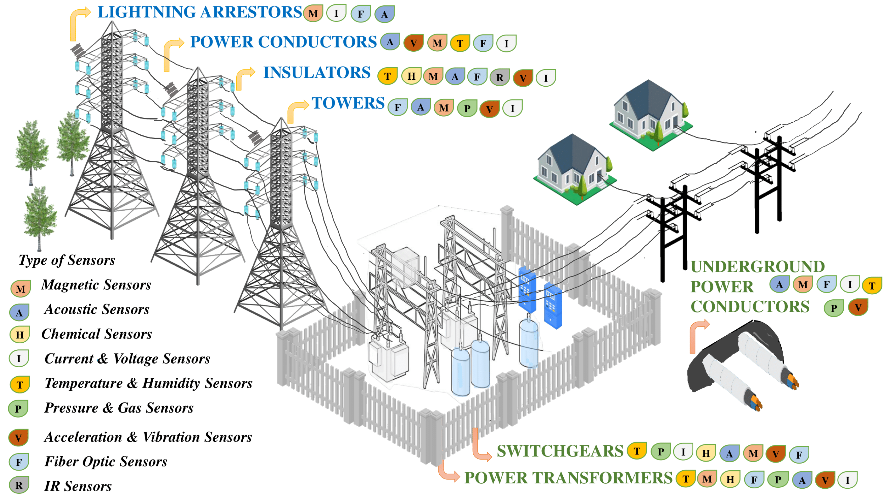
3. Key Transmission and Distribution System Components

Some of the major transmission and distribution system components have been listed below along with various major faults that occur in them during their normal operations in the power grid. Various sensors and their function in mitigating these faults have been explained.

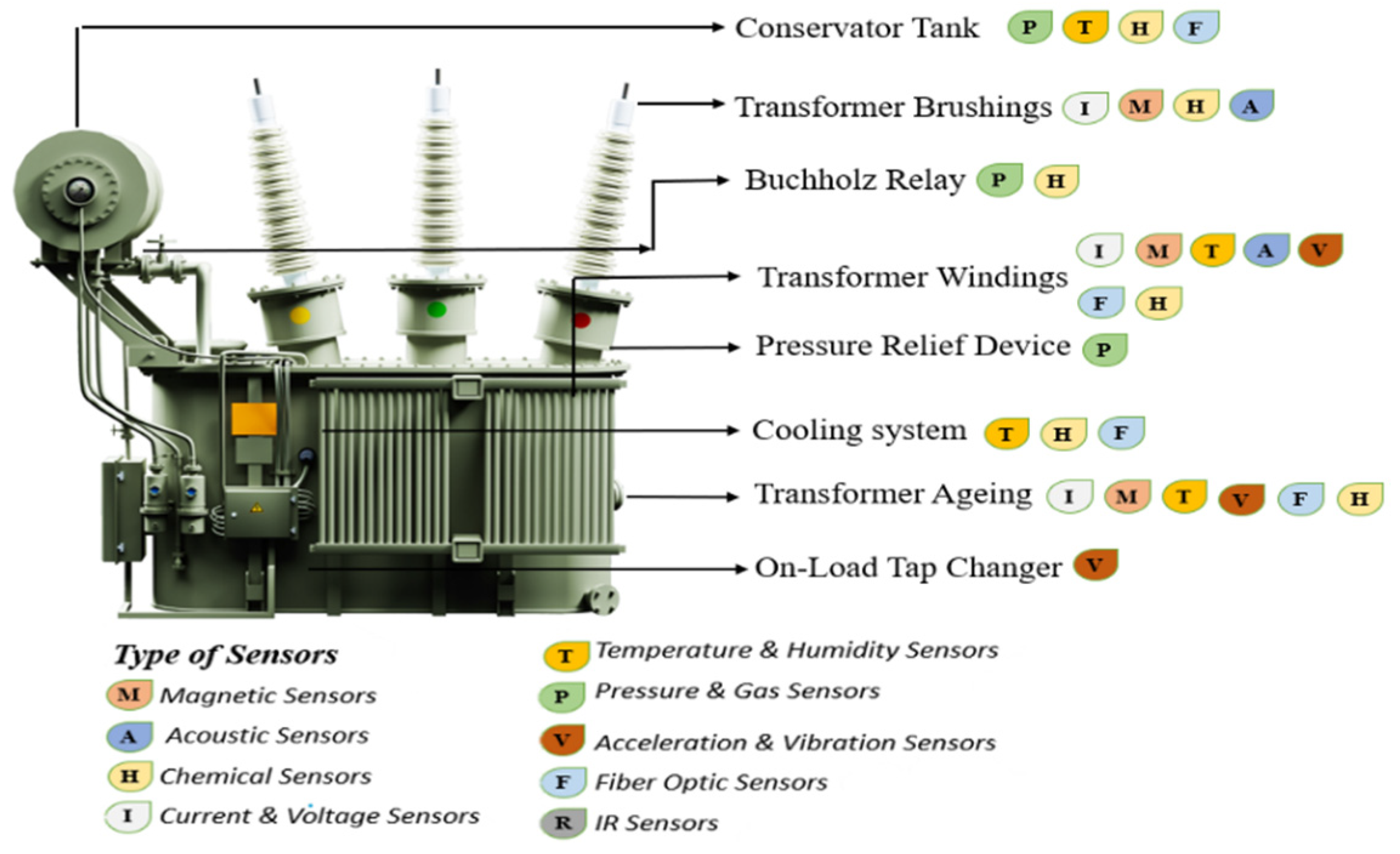
3.1. Power Transformers

Power transformers are the most vital and expensive components of a substation. They are essential in stepping down the high transmission line voltages into lower values for the sub transmission and distribution levels. Despite a sturdy build and a prolonged life span of sixty years with routine maintenance and protective gears like surge arresters attached to them, power transformers are susceptible to many in-service failures and breakdowns which can have results from an increase in transmission losses to the complete breakdown of the transformer leading to fire and other hazards, costing millions of dollars and lives. Power transformers generally get damaged due to the wear and tear of components that mostly occurs because of ageing. Insulation degradation, moisture absorption of the transformer oil and oil leakage can also seriously damage the transformer. Furthermore, lightning, seismic and line surges can severely affect the workings of a power transformer [44]. To monitor these faults, various sensors have been deployed on the power transformers, as depicted in Figure 2.
One of the most used power transformer diagnostics is the monitoring of target specific analytes that often emerge from its malfunctioning and can produce a detectable electrical signal proportional to their magnitude and corresponding to the status of the transformer using chemical sensors. Dissolved gas analysis (DGA) monitoring is conducted to assert the insulant or coolant oil degradation that corresponds to the malfunctioning of a power transformer. Although some form of it has been in use since the 1980s, the modern online dissolved gas analysis systems of chemical sensors [14,45,46] help in the continuous monitoring of temperature, moisture content, and concentration detection of different combustible gases that arise from the transformer oil degradation without disrupting the normal functioning of the transformer. Continuous on-line monitoring and periodic sampling of the insulating oil in the transformer is mostly conducted with dissolved gas analysis that determines the concentration of generated gases such as hydrogen, carbon monoxide, carbon dioxide, ethylene, and acetylene that are studied for the knowledge of the operation and condition of the transformer and helps with the detection and the prevention of any incipient faults. The dissolved gas analysis of load tap changers helps in its maintenance and avoids its failure and the failure of the transformer. Chemical sensors such as semiconductor gas sensors with metal oxides or metal semiconductor oxide materials, electrochemical gas sensors, optical gas sensors with infrared absorption sensors, spectrum absorptive sensors, fluorescence sensors, and fiber sensors are currently used [14]. A metal insulated semiconducting structure-based field effect gas sensor with a low-cost sensor on a chip is used for detecting the release of hydrogen or acetylene gas released during the thermal decomposition of transformer oil [14]. Gas sensors such as the SF6 sensors and, more recently, an improved version of it employing radio frequency signals in the SF6 sensors are used to monitor the gas ratios in a load tap transformer [7].
The modern on-line dissolved gas analysis DGA transformer monitoring system also has advanced chemical sensors to measure the electrochemical and optical signals to determine the condition of the insulating oil. Surface plasmon resonance principle-based optical chemo sensors are also widely used to detect transformer oil degradation. An optical sensor with a molecularly imprinted polymer layer in contact with the surface plasmon resonance active surface is used for the monitoring of an oil-filled power transformer [47]. Here, a highly selective and sensitive molecularly imprinted polymer has been used as an artificial receptor with surface plasmon resonance transduction in the plastic optical fiber for the detection of molecules of furan-2-carbaldehyde in the insulating oil that indicates dielectric breakdown and power transformer failure. Resistive, optical palladium or platinum-based thin film-based sensors and Pt-GaN based Schottky diodes are often used for hydrogen gas sensing that is an essential indicator of the incipient occurrence of faults in power transformers [14]. Methane gas [48] associated with the presence of both thermal and electrical faults are detected with the help of metal oxides-based sensors at high temperatures. For room temperature measurements, resistive, optical and quartz crystal- based thin film and nano wire structure sensors with cryptophane and silica based-electrochemical fabrications are used. Insulation deterioration in power transformers can be detected by sensing the emission of carbon monoxide gas. A combination of electrical and resistive thin film and nanotubes structure-based sensors are used for carbon monoxide detection. Acetylene can be emitted from either overheating due to high temperature and circulating currents, partial discharge or high intensity arching in the transformers. Thin film structure-based resistive and optical sensors with Ag, ZnO, Fe and graphene oxide-based fabrications and fiber Bragg gratings are commonly used for the detection of acetylene.
Various wireless sensing network methodologies have also been developed in theory with transmission and distribution networks for remote system monitoring and data processing of gases emerging from a transformer. One such system is the wireless ultrasonic gas sensor nodes system with a microcontroller and a ZigBee transceiver that is used for binary gas concentration detection such as hydrogen and SF6 in a high voltage substation [49]. There has also been works on fabricating nanomaterials and nanotechnology using semiconductor technology to develop high precision, low power gas detection chemical sensors.
With the change in temperature owing to the dielectric breakdown or circulating fault currents in the transformer, the relative humidity around the transformer tends to change. This change is captured by the humidity sensors to detect fault conditions. High moisture content in the transformer oil also leads to insulation breakdown. Thus, the online moisture content monitoring and humidity monitoring in transformer oil are important aspects. Humidity sensors were previously known to be fabricated with chemically inert polyimides and were immersed in the transformer oil to sense the level of moisture that, when it increases above the threshold, leads to the dielectric breakdown of the oil. Later, capacitive humidity sensors based on polyimide films were incorporated with temperature sensors for the online monitoring of moisture content, relative saturation, and temperature in the oil. Fiber Bragg grating humidity sensors with poly methyl methacrylate are developed with lower detection limits of water content and hence are more effective. Porous ceramics of the ionic and electric types are also used as moisture sensitive materials on humidity sensors. Thin film polyimide and alumina fabricated capacitive and optical humidity sensors [14], as well as poly methyl methacrylate-based fiber Bragg grating humidity sensors, have also been deployed in power transformers. The latest technology uses the platinum nanostructures indium tin oxide substrate to detect moisture in the transformer oil since it has the best sensitivity for detection.
Acoustic emissions are fault indicators produced by the partial discharge in the on-tap load changers as they are employed in the fast switching of load currents between circuits. The operation and technical condition of the on-load tap changers can be diagnosed by analyzing these acoustic emissions. Hydrophone based general purpose sensors, piezoelectric accelerometers and broadband transducer-based sensors are used for the measurement of acoustic emissions in 0 to 90 kHz frequency range. Distributed acoustic and temperature sensing systems that use the temperature, strain, and vibration sensitive Rayleigh backscattering technique-based optical fiber yield more accuracy in fault detections by replacing multiple sensors with a single optical fiber sensor [50]. Alternatively, multiple acoustic sensors are integrated with a preamplifier, a high frequency current transducer, and a signal processing unit with a digital acquisition module to form a partial discharge ultrasonic detector to be clamped on the transformer tank [51]. Also, ultrasonic detection of SF6 and water content in transformer oil [52] is done with special acoustic sensors. Finally, surface acoustic wave temperature sensors with power over ethernet as the system’s power and data transmission line is used for the online temperature monitoring in high voltage substations and power conductors [53]. These sensors are composed of special piezoelectric crystals. Any change in temperature affects the frequency of acoustic waves on the surface of the crystals. The measurement of this change in frequency reflects the corresponding change in the temperature.
Optical fiber temperature sensors [54] can measure the actual temperature of the transformer winding by getting mounted on them directly. There are two kinds of optical fiber sensors: the surface and embedded optical fiber grating temperature sensors. Due to their compact size, they are easy to be embedded into the transformer. The use of wavelength division multiplexing technology makes multiple grating concatenated on the single fiber, realizing quasi distributed networking measurement. These sensors are also suitable for working in a high temperature and high-pressure oil and gas environment. The major disadvantage of optical fiber sensors is that they are quite expensive. Ref. [55] uses unique and cost-effective arrangements of fiber grating temperature sensors for 35 kV, 200 kVA three-phase double winding oil-immersed transformers with internal fluid-solid coupling to detect the transformer hot-spot formation and location under different load conditions. Optical fiber sensors spatially resolve temperature monitoring through mapping temperature hotspots or electrical discharges in specific locations of a transformer. Distributed optical fiber sensors with nanostructure metal oxides are actively designed for the sensing of hydrogen and methane gases. Currently, various methods of spectroscopy wavelengths and techniques such as Raman spectroscopy, transmission spectroscopy, fluorescence spectroscopy, etc. are being studied that can be made compatible with optical fiber sensors [14].
Various miscellaneous sensors have also been installed to provide complete monitoring of the transformers. Ref. [56] provides a review of various sensors placed on an on-site step-up transformer in a substation such as the brushing monitor sensor that could sense the capacitances, leakage currents, and phase-to-ground and phase-to-phase voltages in the transformer brushings. Digital transducers are used in the cooling system of the transformer to sense the temperature in the transformer oil and e water in the exchanger. Additionally, to sense the relative humidity and temperature of a transformer tank, Smart Intelligent Electronic Devices based sensors are installed directly on the transformer body for variable measurement. These sensors have communication ports that facilitate the direct connection to a communication network and make it possible to transmit the measurements directly to a server in the plant’s control room.
The monitoring of mechanical deformations in a power transformer winding is crucial. Aging, the effects of arching faults, or the inefficient handling of transformers can have a loose winding structure that disturbs the symmetry of short circuit forces. These forces create axial and radial forces that might lead to the movement of winding, indentation on windings called buckling, or spacing between the discs. Special Hall effect sensors [57] mounted on the transformer windings can sense the change in leakage flux with winding deformations and help in minimizing the amount of repair and the repair time, saving thousands of dollars.

Sensors on Power Transmission Transformers vs. Power Distribution Transformers

Despite having similar components and working principles which results in similar faults as described above for power transmission transformers, power distribution transformers differ in their sizes, ratings, and costs. Power distribution transformers are generally smaller in size, with ratings ranging from 11 KV, 6.6 kV, 3.3 kV, 440 v, and 230 volts, whereas the ratings of power transmission transformers which deal with significantly higher voltages of the transmission lines can range from 400 kV, 200 kV, 66 kV, and 33 kV [58]. Due to lesser sizes and ratings, the price of power distribution transformers can be as little as $700 [17]. Hence, the fault detection and health assessment solutions for distribution transformers must be economical [17], since it won’t make sense to have sensors and wireless sensors systems that are more expensive than the transformer itself. Distribution transformers are either pole mounted with oil-based, polymeric, or air-based insulation or substation-based with only oil-type insulation. Apart from the faults discussed above for power transmission transformers, power distribution transformers also undergo insulation failures such as water accumulation, aging or thermal degradation of polymeric paper. Furthermore, distribution transformers are more prone to overloading and unbalanced loading. This is because distribution transformers are generally governed by the end-user or the consumer, making them an uncontrollable load [59]. Uncertainty in load, especially with the recent integration of PV, EV charging stations, etc., further contributes to this cause. Overloading and unbalanced loading can distort the normal circulation of a current, thereby increasing the winding and oil temperatures, resulting in subsequent winding failure and insulation degradation. However, due to the economic aspects, winding temperatures are selected as the primary monitoring parameter [60], and other parameters like changes in current, aging, etc., are detected from the change in winding temperature [61]. For temperature monitoring, distributed temperature sensors are placed on the distribution transformer windings. Recently, fiber optic sensors are being popularly used due to their accuracy in hot spot determination. Furthermore, fiber optic sensors are low in cost and size and can provide measurements during in-service operation with immunity to electromagnetic interference [16,62]. In addition, various machine learning techniques are being employed to forecast winding temperatures and to build a thermal model to predict anomalies in thermal behavior in the future. Ref. [63] proposes an online transformer health monitoring system using the global mobile service (GSM) with a resolution of 15 s to improve the monitoring process. However, the use of GSM modules and microcontrollers makes the system expensive. Ref. [64] uses a low-cost solution to utilize the data collected from advanced metering infrastructure (AMI) meters for distribution grid asset management. To reduce the amount of data complexity, Ref. [65] uses hourly usage data from AMI and SCADA to determine distribution power transformer failures and overload. The model also uses a geospatial information system (GIS) for geolocation of distribution system instruments and its faults and a customer information system (CIS) for a database of historical information of customer loads and outages. Apart from this, studies are ongoing to introduce low-cost health condition monitoring of power distribution transformers with IoT for smart grids [66,67,68].

3.2. Overhead Line Power Conductors

Overhead line power conductors are essential for transporting power over long distances and are prone to high voltages and severe atmospheric conditions that lead to its deterioration. Overhead line power conductors form a part of the transmission systems as well as the distribution systems. Some of the causes of such deterioration are explained as follows. Conductor corrosion is a common phenomenon occurring from galvanization due to atmospheric pollution. Vibration damage such as aeolian vibration, galloping, or sub conductor oscillations put severe mechanical strain on the power conductors. Severe atmospheric conditions such as heavy wind, rain and snow also have variable effects on the power conductors, such as sagging and breaking of the conductors [18]. Various sensors have been developed for monitoring these faults and are discussed in the following paragraphs.
The monitoring of overhead line power conductors is conducted in one way by measuring the changes in mechanical structure of the conductors that can occur due to aging, corrosion or vibration damage leading to loss of material, putting extra strain on the conductors, and reducing the transmission capacity. Magnetic sensors help in the detection of magnetic field enhancement because of defects in the cable insulation. Air gaps and protrusions in XLPE insulation [69] lead to enhancement in the semiconductor layers that alter the magnetic field, and its detection is very useful in the degradation monitoring and evaluation of medium voltage power cables in transmission lines. In [70], TMR sensors are mounted atop support towers of high voltage transmission lines to sense the change in magnetic field with the change in sag of the power conductors as well as conductor motions such as swinging and galloping effects caused by changes in weather conditions. These sensors are synchronized with the current transformers to give real values of data synchronized in time and space. Among other methods of overhead line power conductor monitoring, unmanned aerial vehicle (UAV) inspection [71] has been developing recently. Fixtures of multiple sensors on UAVs can help sense the electric and magnetic field around the transmission line and the distribution of line power conductors. Ref. [72] uses TMR sensors on UAVs for magnetic field measurements and the reconstruction of position and current parameters of the transmission line.
Current monitoring is also conducted to detect leakage current due to partial discharge in the form of corona or gap discharges, breakage of conductors, etc., that would otherwise lead to unnecessary dissipation, reducing the transmission capacity. Various sensors such as Hall effect-based magnetic sensors, current sensors, and optical sensors are used for measuring the power conductor fault currents. Fiber optic current sensors [18] are based on optical reflection sensing where the reflection of light estimates the leakage currents. These sensors are compact, non-invasive and replace bulky and lossy current transformers at substations. These sensors can be installed in remote sites with large bandwidth, greater signal to noise ratio and no saturation issues. An advanced version of it, an optically interrogated Rogowski coil, is developed by interfacing an optical low voltage sensor and a piezoelectric stack transducer with a fiber Bragg grating to the output of a Rogowski coil for effective operations at higher power conductor harmonics [73]. Piezoelectric-based acoustic sensors are also used for the monitoring of partial discharges.
The increase in conductor temperature can be caused by lightning surges, overloads, or short circuit faults. Temperature monitoring is essential to identify and limit sag as well as partial discharges, corona discharges, etc., as well as to check breakage, elongation and increases in tensile strength of the conductor. Temperature sensors such as air and solar temperature sensors are being replaced by surface acoustic wave SAW temperature sensors, since they have the advantage of high temperature sensitivity and high temperature coefficients with low delay time [74]. Optical fiber-based sensors called Sagometers [20] are also used for temperature measurements in low and medium voltage power conductors.
An increase in temperature and thermal stress could also lead to an increase in sagging of conductors, which if unchecked can lead to the damage and breakage of power conductors. Fiber Briggs grating-based optical sensors have been developed that can check the sag by monitoring the tension and the strain on the power conductors [75]. Optical and optoelectronics-based vibration sensors have also been used to detect the vibrations of the power conductors. The frequency of vibration below a threshold value signifies the increase in sag in power conductors above the permissible limit. Currently, unmanned aerial vehicle-based sag measurement based on image processing techniques are being used [76].]. Robots with multiple sensors are also used, especially in live high voltage transmission lines, to monitor the sag as well as temperature, vibration, humming sounds, etc. Examples are a semi-automated robot system named Line ReconRobot and a power line inspection robot named ROSETLineBot. [77]. Another relevant device called overhead transmission line monitoring (OTLM) [78], which is embedded with multiple sensors, can monitor temperature, wind speed, inclination, current and humidity and can calculate sag and tension measurements with the help of the sensed measurements. These sensors can monitor high voltage power conductors with voltage levels of 500 kV and transmit the sensed parameters along with GPS timestamps through cellular, LoRa, Wi-Fi or satellite networks to the utility server. Finally, the installation of dynamic line rating (DLR) systems [79] requires knowledge of the real time thermal rating of the overhead power conductors to optimize the ampacity and establish dynamic limits on the conductors according to real time weather variations. For this reason, these systems utilize various temperature sensors such as stick-on wireless temperature sensors, ThermalRateTM systems, TLMTM conductor monitors, power donutTM, SAW-based temperature sensors, thermal infrared cameras, etc. [80,81,82]. Additionally, DLR systems are also known to employ various distributed sensors for online monitoring of conductor tension, sag, clearance-to-ground, and humidity. Thus, multiple sensor technologies that have been developed to detect various faults in the transmission line and distribution line power conductors have been discussed here.

3.3. Overhead Line Insulators

The major functions of overhead line insulators include reinforcing mechanical strength to the power conductors to withstand external loads and provide a high resistive path to the leakage currents. The most used types are pin type insulators, suspension type insulators, strain insulators, shackle insulators, disc insulators, stay insulators, etc. Overhead line insulator faults include the puncturing of insulators and their degradation owing to aging, mechanical stress, electrical stress, and atmospheric pollutants that can cause dielectric breakdown leading to flashover [83]. Various sensors have been deployed to monitor the above-mentioned failures in the overhead transmission line insulators.
Traditionally, the monitoring of aging in the commonly used silicone rubber insulators was conducted by analyzing the shape of water droplets, known as hydrophobicity analysis, or by measuring the leakage current flowing through it [84,85]. These types of fault analysis are being conducted by infrared thermography [83] that detects the temperature rise of the insulator resulting from partial discharge. It can also detect voids, cracks, and tracking damages. The electric field method was previously used to detect defects but mostly includes the insertion of wires and hence was rejected due to its destructive methodology [86]. Also, the diagnosis of faults in the insulator becomes difficult in humid or polluted conditions with these methods. Hence, they are being replaced with nondestructive methods such as X-rays for obtaining an integral view of interested parts or a whole insulator. However, the degree of absorption of X-rays is dependent on the density, consistency, and the thickness of the detected objects and thus it is difficult to detect smaller cracks and defects. Computer tomography was also used for the detection of smaller cracks and defects. Computer tomography detects air bubbles in glass fiber reinforced polymer cores of hollow-core composite insulators [87]. Scanning electron microscopy, Fourier transform infrared spectroscopy, X-ray photoelectron spectroscopy, and thermally stimulated currents are also conducted for the determination of aging [88]. However, these methods can examine only very thin layers and fail to measure the deeper layers under the surface. Recently, for accurate estimations, sensors are being used to sense the change in the crystal lattice of the structures and perform material analysis at microscopic levels. Magnetic sensors such as TMR sensors [34] are used to detect the arcing and chattering phenomenon of insulators which is an indication of wear and tear due to aging. A novel nuclear magnetic resonance sensor is employed for 1D depth profile measurements to estimate the aging behavior of a silicone rubber insulator [89]. However, these sensors employ weak static magnetic fields that cannot penetrate multiple depths. Ref. [90] uses unilateral magnetic resonance sensors to excite multiple layers and gradients of the rubber with a static magnetic field of constant gradient and a radio frequency magnetic field of fixed frequency to detect the complete change in lattice structure due to aging.
Excessive electrical stress can cause the flow of leakage currents in insulators, monitoring which becomes essential for the early detection of emerging faults such as high voltage build up, flashovers and insulation material degradation. Fiber optic sensors have been used for measuring insulator leakage currents for high voltage transmission lines [91]. Here, sensors employ highly efficient LEDSs that are driven by the leakage currents flowing from high voltage lines to the ground for its detection. le. However, these sensors have several side-effects such as optical power drift due to temperature and aging, modal instability, and macro-curvature losses. Recent developments have been made to reduce these errors by using plastic optical fiber technology [92] that uses the LED output light modulated by the insulation leakage current to energize a plastic optical fiber that then transmits error signals via GPRS to a remote terminal unit. This type of fiber optic sensor has the advantages of immunity to electromagnetic interference with the use of plastic cladding along with being low cost and lightweight which makes their installation easy [93].
The monitoring of atmospheric pollutants on the insulator surface is essential for the early detection of incipient mechanical and electrical stresses. Ref. [94] uses a unique sensing system made up of multiple optical fiber sensors based on Brillouin scattering and fiber Briggs grating. Brillouin scattering gives better strain and temperature coefficients to sense the strain in overhead line insulators due to deposits of heavy pollution or ice. Ref. [95] uses a salt deposit density based optical fiber sensor with a micro-controller unit, A/D converter, quartz fiber, photodiode, laser module, data flash memory, solar panel, and sensors of temperature, humidity, and communication modules. This module can effectively monitor the presence of different densities of salt that are deposited on the transmission line insulators as pollutants with equivalent salt deposit density and non-soluble deposit density as the indicative parameters. Shearography [87] is another optical method that uses coherent light or sound waves to detect flaws, delamination, and deboned areas in composite systems.
Mechanical and electrical stresses stemming from aging, poor maintenance or harsh atmospheric conditions could deteriorate the insulator surfaces causing insulation breakdown. The monitoring of occurrence and location of these discharges is essential for repair and replacement of faulty insulator components. Ultrasonic techniques-based position, vibration and optical sensors have been used to detect these defects and discharges in insulators [96]. Acoustic emissions from a faulty insulator produced by corona discharges can be monitored by acoustic sensors to detect the origins of the fault. However, these emissions are very sensitive to background noise, which makes the determination of the defect location difficult. To remedy this, a non-destructive ultrasound technique is used that relies on listening to echoes of sound signals coupled to the tested objects. The location and nature of defects are analyzed based on signal parameters such as the amplitude, time, and phase shift of the returning signal. A scanning laser acoustic microscope uses high frequency ultrasonic waves in the MHz to GHz range for detecting delamination and misorientation of fibers in fiber reinforced plastics [87]. However, due to the fixed focus and single angle beam interrogation, these ultrasonic techniques fail to detect minuscule defects at different depths of the insulator, for example under insulator sheds, etc. To remedy this, ultrasonic nondestructive testing based on the ultrasonic phased array technique has been developed that is efficient in inspections of objects having complex shapes, location of defects at different depths and identifying different types of defects on the insulators. Ref. [87] uses the technique for detecting internal defects such as air voids, paper strips, drill holes under sheds, interfacial air gaps, etc. in composite insulators. Thus, various sensor technologies developed for the detection of faults in transmission line insulators have been discussed here along with their detailed operations.

3.4. Distribution System Switchgears & Protective Devices

The distribution system consists of an array of instruments for protection such as circuit breakers, relays, reclosers, sectionalizers, fuses, etc. that protect the power conductors, power transformers and distribution side equipment from high voltages and fault currents. Fault currents tend to affect the protection schemes by leading to sympathetic tripping, reduction in the reach of distance relays, loss of relay coordination, etc. Traditionally, faulted circuit indicators were used to locate faulted line sections. The fault level was indicated by faulted line sections. The fault level was indicated by setting up a mechanical target like a flag or an LED. However, this process is slow and introduces a lag in the communication between the protective devices such as a recloser with the downstream devices such as fuses or other reclosers, and hence delays the time to clear faults. Ref. [97] provides literature on the development of a wireless protection sensor system that speeds up the fault detection speed. This system consists of multiple sensors that are placed per phase along distribution feeders, closer to the point of the occurrence of the fault. After sensing, they send the fault status to a collector which then sends the received status to the recloser control at high speed, securely speeding up the operation and improving the selectivity of the distribution protection scheme. The breakage of power conductors in the feeder and distribution section is a very common phenomenon that usually happens because of heavy wind flow during events such as cyclones. If the supply from the power transformer is not cut off, it can pose the risk of electrocution to the maintenance personnel. GMR-based sensors [98] mounted on feeder lines help to capture the alternating magnetic fields that correspond to the high levels of current, which is an indication of the state of energization of the cables.
Circuit breakers are important switching equipment of the distribution system that performs the dual task of control and protection. Due to continuous interruption action, they undergo severe mechanical stress and wear and tear. Any physical deformations can be sensed with the help of mechanical sensors such as stress gauges. Recently, with the development of fiber optic sensors [99] vibrational fiber optic sensors have been developed for sensing wear and tear on the vacuum tubes of a circuit breaker. Sagnac interferometer-based fiber optic devices are also used to detect mechanical faults through changes in the frequency of acoustics. The wear and tear due to aging or contamination can also cause the insulating material within the circuit breaker to deteriorate, which can result in partial discharge due to the ionization process. Photo sensitive fiber-based optical sensors [11] are used to detect these partial discharges. However, these sensors can only operate in a constant electric field. Any change in electric field will generate partial discharges in the fiber. Arc control in circuit breakers is essential to constrict the effect of thermal emissions and eradicate the breakdown of the anode at high current levels. This is conducted with the help of axial or radial magnetic fields that force the arc from the fault current to rotate. The motion of the arcs in lifetime sealed circuit breakers, especially vacuum circuit breakers, can be sensed through Hall sensors [100]. Other sensors fail since the vacuum is sealed with an opaque ceramic and metallic vapor shield. In addition, in a vacuum circuit breaker, knowledge of the density of electrons in the electrodes, gases and the plasma are important. A unique Shack-Hartmann type laser wavefront sensor is described in [101] that can visualize two-dimensional electron and metal vapor density distributions. Optical emission spectroscopy [102] has also been used to detect the metal gases evaporating from the electrodes.
Temperature measurement and monitoring is essential in circuit breakers. This is because in SF6 breakers, liquefaction of SF6 gas occurs at extremely low temperatures, affecting the arc interruptions. For this, temperature sensors mounted on the circuit breaker are used to indicate this drop off in temperature below a threshold value. Intelligent temperature control systems [103] with wireless temperature control units and heating units, lined with temperature sensors to sense the drop in temperatures and automatically start the heating unit to keep the gas from liquefaction, have also been developed for faster response. Furthermore, surface acoustic wave-based online temperature monitoring systems [2] have been developed to be mounted on the circuit breakers. This system consists of a piezoelectric substrate with an interdigital transducer and acoustic reflection grating. A change in temperature or pressure in the windings will be detected since it affects the transmission of frequency of acoustics on the piezoelectric substrate.

3.5. Transmission Line Towers

Transmission towers are an important part of the electrical grid since they reinforce the continuity of transmission line power conductors and host an array of power conversion, protection, and insulation devices along with providing ground resistance. Transmission towers are bulky and complex structures and are prone to displacement, inclination, cracking, vibrations, and subsidence. The resulting effects of these issues can cause severe problems such as interruption of the transmission lines and communication networks, transmission line galloping, settlement tilt of the transmission tower and even the collapse of transmission line conductors or transmission tower collapse [104]. These effects are mostly caused by natural phenomena such as heavy rain and snow and high wind speeds. However, in certain cases, these effects can be a result of design or force-fitting flaws during erection or material defects. Depending on the pattern of the failure, there are two major transmission line tower faults [105]. A local failure in the transmission tower occurs due to the failure in the primary or secondary bracings. This does not lead to the complete collapse of the tower structure and is often detected through manual inspections. The second type of failure occurs because of failure in the tower leg or legs causing the failure or collapse of the foundation of the tower. This is called structural failure. Due to its severity in nature, various sensors have been deployed to monitor the structural failures in the transmission line towers such as transmission tower tilt, transmission tower vibrations, the loading effects of ice and wind, and structural and wielding defects.
Structural health monitoring technology [19] has been widely used in assessing the damage in the power tower structure. The most common method of measuring tower tilt is conducted with an inclination sensor [106] fitted to the transmission towers. However, inclination sensors can only indirectly reflect the state parameters of stress and load balance when the whole deformation of the tower is large. To detect small deformations on the tower or the yield failure of the local power conductors, pressure and strain sensors are used on the transmission towers. These sensors have a lower measurement range and can successfully sense damages of smaller magnitudes. Currently, fiber Briggs grating-based strain sensors have been developed that have improved range and accuracy for sensing [12].
The vibration response of the tower changes with the change in load and environmental conditions and the formation of mechanical defects, thereby reflecting the structural status of the transmission line tower. Acceleration sensors mounted on the crossarm of the tower are used to measure the vibration response of the system as a part of structural health assessment. An excitation device is used to generate impulse excitation which causes forced vibrations in the tower and the corresponding signals are sensed by the acceleration sensor. Ref. [107] uses a MEMS-based three-axis acceleration sensor that calculates the difference between the acceleration due to a combination of gravity and other stresses and the acceleration due to gravity alone, thereby detecting vibration responses from faults on the transmission line towers. Optical fiber sensors are known to have larger bandwidths and lower frequency ranges for sensing. Hence, fiber Briggs grating sensors have been used to measure vibrations caused by surface displacements as well as the deep displacements of the transmission line tower.
The loading effects of ice and wind can cause various structural displacements to the transmission tower structure, and thus their monitoring is essential. Optical sensing-based fiber Briggs grating sensors [108] are used to monitor the ice load effect of inundated ice on the transmission towers. These sensors work on the principle that the wavelength of optical fiber varies with the change in strain and temperature due to the loading effect of ice, etc. Fiber Briggs grating is fast becoming popular due to its immunity to electromagnetic interference, the lack of a requirement for a power supply on site, and the immunity to harsh chemical environments with a longer lifespan than other sensors. Optical fiber composite ground wires and FBG load cells are most popularly used for tower monitoring. An all-optical fiber sensing system is developed in [12], where an optical sensing probe is made by coaxially splicing a thin core fiber with tilt fiber gratings inscribed into its core. The sensing probe is mounted on the transmission tower and provides the measurement of two wavelength-separated spectral signatures, one from the core-guided mode and the other from the cladding mode. The optical power of the cladding modes provides real time amplitude and frequency of vibration of the transmission tower. The power of the core mode provides in situ measurement of temperature and inherent self-calibration to remove the fluctuations of light source intensity and loss in optical transmission. In ref [109], measurement of on-line strain, generally caused by transmission line galloping is conducted by using fiber reinforced plastic packaged fiber Bragg grating sensors. The strain coupling is between the angle braces and sensors at a different position on the transmission tower.
In certain cases, design flaws in the tower structure can stem from irregular force fitting or wielding defects during the construction of the transmission tower. Over time, these defects could lead to the buildup of residual stress, resulting in mechanical deformations and occasionally causing tower collapse. Various non-destructive testing methods such as radiation testing, ultrasonic testing, eddy current testing and leakage flux testing have been employed recently by installing current sensors, ultrasonic sensors, or magnetic sensors such as MR sensors, fluxgate sensors, and Hall sensors on the transmission towers. An example of this is the deployment of [110] an array of 64 GMR sensors that are used to detect the changes in magnetic flux density due to mechanical deformations in tubular type transmission towers [110].
Currently, the remote and real-time, on-line monitoring of transmission towers has gained a lot of interest. In [111], transmission tower tilt angle prognosis is conducted with the help of a solar-powered LoRa sensor node which consists of a solar panel, a LoRa radio frequency chip, super-capacitors, accelerometer, and gyroscope to measure the initial tilt angle and the angular rate of the transmission tower which is wirelessly transmitted to control center through LoRa gateway. In [106], multiple inclinometers that can measure the transmission tower tilt with respect to the force of gravity are used to detect the tilt and broken materials of the transmission tower with low powered NB-IoT technology. However, the installation of these sensors is limited due to the requirement of power supply for data sensing, data transmission, etc. A new generation of remote sensing technology employs unmanned aerial vehicle UAV with LiDAR or laser scanning sensors [112] that have high density and high penetration ability. They take laser pulse as a measurement medium to obtain high-precision 3D coordinates of target areas in the transmission tower to accurately measure the tilt rate of the transmission towers.

3.6. Underground Cables

Recently, overhead lines are being rapidly replaced by underground cables since they provide better safety, stability, security, and reliability to the overall grid structure. Underground cables can form a part of the transmission system as well as the distribution system. Even though the chance of outage is reduced since the cables are buried into the soil, they are still vulnerable to major faults due to partial discharge, rise in temperature and cable aging causing wear and tear over time, etc. This makes fault identification and prevention and repair of cables difficult and expensive. Thus, a large variety of sensors have been developed and deployed for fault detection and the fault monitoring process in underground cables.
Partial discharges are the most common faults seen in underground power cables. These faults occur due to improper installation and maintenance, the circulation of large load currents, or substantial increases in temperature inside the power cables, leading to insulation degradation around the power cables, especially at cable joints. This deterioration of insulation material causes partial discharges in the underground power cables. Partial discharges can have harmful effects and cause surface discharges, corona discharges around sharp edges, internal discharges leading to electrical treeing, etc. Hence, detection of partial discharges is essential to detect the occurrence of insulation degradation and to avoid the further breakdown of underground power cables.
Various sensors have been developed for the detection and location of partial discharges in underground cables. Traditionally, ultra-high frequency coupling capacitors, vibration sensors, high frequency current transformers and Rogowski coils were used to detect partial discharges. The acoustical analysis is another method for the detection of partial discharge. Ref. [113] uses an FBG optical sensor to record the acoustic emissions caused by defects in the insulation layer. The captured acoustic waveforms are then studied with signal processing techniques and its characteristics such as loudness, fundamental frequency, pitch, and quality are investigated in the time domain and frequency domain for accurate classification of nature and source of partial discharge faults. However, since cables are buried underground, the acoustic method of sensing has a disadvantage wherein the sensors are required to be placed in the vicinity of the source and hence their installation becomes more difficult and expensive for underground cables. Acoustic signals also suffer from attenuation while transmission due to the interference by surrounding power system equipment.. Ultra-high frequency methods, on the other hand, do not suffer from the above disadvantages. These methods include the generation of RF signals to detect the location of partial discharges. [114] uses radio frequency current transformer sensors to sense the RF signals generated from the source. Here, three sensors are clamped to the three phases of the ground wire of cable joints to detect the partial discharge signals. Ref. [115] uses ultra-high frequency sensor-based antennas to capture and transmit the radio frequency signals in XLPE cables for detection of partial discharge. When the length of the cable spans to several kilometers, there might be multiple sources of partial discharge which would require the use of multiple sensors that would not be cost effective. Ref. [116] proposes a method of partial discharge detection from multiple sources on long distance cables through the time domain reflectometry method. Here, the time of arrival of the partial discharge pulses received at the sensors along with its subsequent reflected pulses, the wave propagation speed, and the total length of the cable is considered to locate the sources on the power cable. Hence, it is noteworthy to elucidate and appreciate the variety and multitude number of sensor technologies that have been developed for monitoring partial discharges in power conductors.
Temperature monitoring in underground cables is conducted to detect any abnormal increase in temperature that could be a precursor to many faults. It is often very difficult to mitigate rising temperatures in underground systems because the power cables are not surrounded by air but rather by soil with very low humidity. Also, the underground power cable tunnel has very poor ventilation and very low natural heat convection. In such cases, if the rising temperature goes unhindered, it will decrease the efficiency of power transmission and lead to insulation failures, short circuits, the malfunctioning of equipment and even explosions leading to fires. Traditionally, cable temperature monitoring was conducted with point type or thermal infrared technology [117]. Point type technology had temperature sensors installed on key points on the conductor for small distance monitoring purposes. The second technology had infrared sensors to sense the light emitted from the source to convert it into heat to measure temperature [118]. However, this method is dependent on the emissivity of the source as well as the interference from the surrounding objects which makes its accuracy lower. To mitigate this, optical sensors based on fiber Briggs grating and Raman scattering are preferred [119]. Autonomous robots are also used in the temperature monitoring of underground cables. Ref. [120] designed an IoT based temperature monitoring system with LM35 temperature sensors with a battery system and wireless transmission protocol with smart cloud service analysis.
Cable aging is another important parameter, and its consideration is essential in fault monitoring systems. Cable aging can be caused by thermal, mechanical, or electrical stress or moisture ingression on the cable over time. Since the power conductors are buried underground, the visual inspection of cables is not possible. Undiagnosed cable aging can lead to insulation failure, short circuits and power conductor breakdown, hampering the transmission of energy. Therefore, it will be a difficult and expensive task to replace the entire cable since it is buried underground. The detection of cable aging has been conducted through various ways. Traditionally, off-line methods such as the study of dielectric response and impedance phase detection were used, but currently various on-line methods have been developed. One of the methods used in [121] uses magnetic sensors to measure the common mode leakage current since the aging of cables is accompanied by an increase in relative permittivity that in turn increases the insulation capacitance and conductance of the cable, thereby increasing the flow of leakage current. Ref. [122] uses pressure sensors to monitor the change in pressure around XLPE-SR cable joints, indicating mechanical stress leading to cable aging. The dielectric loss angle is another crucial parameter indicating the aging of cables. Ref. [123] uses current and voltage sensors to calculate the dielectric loss angle along with the Grubbs criterion and adaptive weighted data fusion algorithm-based data processing for accurate aging estimation of an XLPE cable. Thus, multiple sensor technologies have been discussed for the detection of various major faults in underground power cables.

3.7. Battery Energy Storage Systems

The battery energy storage systems are being widely used for the large scale storage of energy and form a big part of the distributed energy systems. It essentially consists of battery modules with a battery management system and an energy management system. Traditional grids, as well as microgrids and smart grids, have been integrated with battery energy storage systems to not only improve the operating reserves and ease grid congestion but also to help with frequency regulation and voltage stabilization. They can also increase the utilization of the grid by ensuring continuous and dispatchable supply despite the intermittent nature of renewable energy sources. Despite their numerous advantages and widespread use, they are susceptible to fires and explosions. The reasons can be thermal runaway, where there is an intense increase in temperature inside the battery, or mechanical runaway, which is caused by mechanical deformations to the battery unit causing short circuits inside the battery cells or the disintegration of its inner components. However, the most common reason for breakdown is caused by electrical runaway that occurs due to overcharging, undercharging or shorts caused by the interfacing inverters. Various sensors have been developed to detect these faults in a battery energy management system.
When a sufficiently sized battery energy storage system is on fire, the DC power arc is very large, and that makes it very difficult to extinguish the initial fire. It also releases toxic combustible gases such as carbon monoxide and methane that cause severe human casualties [124]. Hence, the prevention of fire is essential. Ref. [125] uses a sensor module to detect electrolyte off-gases, which are a combination of gases of ethylene carbonate, ethyl methyl carbonate, diethyl carbonate, dimethyl carbonate, and propylene carbonate that are released in lithium ion-based batteries prior to a fire, indicating a thermal runaway. The sensor module has a combination of electrochemical sensors including photo-ionization detection-based gas sensors, humidity, and temperature sensors. The main job is to monitor the target electrolyte off-gases, discontinue the charging or discharging of the battery, and to disconnect the connection from the charging devices once they are sensed above the threshold level.
A host of sensors are used for the accurate state estimations of battery energy storage systems. Fiber optic current and voltage sensors are used for accurate estimation of state-of-charge and state-of-health estimations with over-current and over-/under-voltage protections. Islanding and anti-islanding are common features of a microgrid. However, sometimes these might initiate high circulating current that can be bidirectional in nature. Furthermore, there can be voltage and frequency fluctuations that could damage the inverter and lead to equipment failure including the battery energy storage system. Ref. [126] uses an array of sensors to monitor essential parameters such as current, voltage, frequency, active and reactive power, total harmonic distortion, etc. at the point of common coupling to provide anti-islanding protection. Furthermore, machine learning based classification techniques such as convolutional neural networks [127], support vector machines, etc. are being increasingly used for the detection of battery faults arising from aging, breakage, EMI noise, etc. by using data from the current, voltage, and temperature sensors. Thus, multiple sensor technologies and their operations have been discussed for the detection of various major faults in battery energy storage systems.

3.8. Lightning Current Monitoring Systems

Lightning is a high intensity natural discharge of electromagnetic pulse that causes black-flask or shielding failures leading to transmission line trips [128]. Hence, protection against lightning is important to safety monitoring and operation in power transmission and distribution networks, and sensors are being widely used for this purpose. The accurate estimation of lightning parameters is essential to building an effective lightning protection system. Lightning location systems are automatic detection equipment that use characteristics of sound, light, and electromagnetic waves radiated by lightning strikes to estimate the lightning discharge parameters. Broadly, they are either ground based or satellite-based systems [128]. They use several types of sensors to detect lightning parameters with various methods such as acoustic methods, optical methods, and electromagnetic field methods. A detailed description of the operation of various sensors in the lightning current monitoring systems has been described in the following paragraph.
Sensors are essentially mounted on the lightning current monitoring systems to detect high voltage lightning strikes. Ref. [129] depicts the working of a system with four 500 kA current transformer sensors designed to capture the magnitude of current strokes arising from the incidence of direct lightning. These sensors are also integrated with IP cameras, position sensors and electric field sensors to estimate other lightning current parameters such as position, latitude and longitude information, time of lightning strike, shape of lightning current, lightning current peak, duration, polarity, frequency, and number of components during the stroke. Ref. [130] describes a low-cost lightning detection and waveform storage system with current sensors used for recording both close and far lightning events with good amplitude resolution without saturation issues. Apart from this, other lightning monitoring methods used are the traveling wave method where the lightning position can be obtained by calculating the time difference in the arrival of transient voltage and current traveling waves at different sensors and the fault type is detected from the traveling wave shape. Ref. [131] uses a TMR magnetic sensor module-based travelling wave method. However, these methods suffer from disadvantages such as weak anti-electromagnetic interference ability, maintenance issues, high cost, influence of terrains, etc. To overcome these issues, optical fiber composite overhead ground wires [132] are being installed on transmission lines over 110 kV, which consists of distributed optical fiber sensors that capture external vibrations due to transient currents through the principle of optical time domain reflectometry. It also helps in the accurate determination of transmission line vibration, temperature rise, polarization state and lightning positioning. Magnetic tape and counter based sensors are used to calculate the number of lightning strikes. The conventional lightning arresters are made up of metal-oxides and have a limited-service life. Ref. [133] replaces the conventional arresters with a magnetic tape-based multi-chamber arresters that use a lightning event counter to calculate the number of lightning strikes and facilitates faster arc quenching with low maintenance and a longer life span. High voltage equipment sensors combined with integrated electronic devices IEDs, or lightning imaging sensors are being used to increase the accuracy and reliability of locating and measuring lightning events with measurement digitization, control networking, state visualization and function integration. Current transformer based intelligent sensors are integrated with IEDs to detect the transient rise in ground potential in the event of lightning. Another example is use of optical current transformers whose operations are based on magneto-optical Faraday effects. [134]. These sensors can perform contactless sensing with higher dielectric strength, stronger anti-interference ability, no bandwidth limitation and no magnetic saturation issues.

3.9. Summary

Table 2 attempts to provide a summary of some of the major developments in sensor technology and their unique applications in transmission and distribution systems. The latest developments in sensor technologies have substantial influences in the monitoring and control of some of the key components of the power grids that can be summarized in the following manner. The modern-day power transformer is equipped with low cost and contactless optical sensors to enable online dissolved gas monitoring DGA analysis [14]. Furthermore, uniquely fabricated gas, chemical and humidity sensors have been used for more accurate detection of target specific analytes in transformer oil. Detection of partial discharges is not just limited to current and vibration sensors. Various unique sensors such as acoustic sensors, ultrasonic sensors, piezoelectric sensors, and optical sensors have been used for this purpose for better fault detection as well as fault location. Finally, complete monitoring of the transformer body is now being realized with smart IED-based sensors as explained in Table 2. In transmission line and distribution line power conductors, the detection of power conductor vibrations along with the sagging and galloping of transmission lines are being more accurately detected with newly developed MR sensors, surface acoustic wave SAW sensors, and ultra-high frequency UHF based vibration sensors [18]. In transmission line insulators, the latest sensor technologies such as infrared thermography and fiber optics-based sensors have been deployed for the efficient detection of faults arising from insulation deterioration and partial discharges [87,93]. Efficient fault detection in transmission line towers through structural health monitoring is currently being realized with MEMS-based acceleration sensors [107]. Furthermore, remote and on-line monitoring of underground power conductors are now possible with Wi-Fi, LoRa, ZigBee, and other wireless-based sensor networks [120]. Arc control and the efficient temperature monitoring of circuit breakers are currently being realized with the help of emission spectroscopy-based optical sensors [101]. The deployment of infrared position sensors with cameras as well as newly developed magnetic and fiber optic sensors have made it possible to locate the position and frequency of high voltage lightning strikes through lightning current monitoring systems [132]. Thus, it can be inferred that sensors have become significant components of the transmission and distribution systems since it has become a prime area of research among researchers and engineers who are continuously upgrading and improving these sensors by integrating them with newer technologies.

4. Outlook

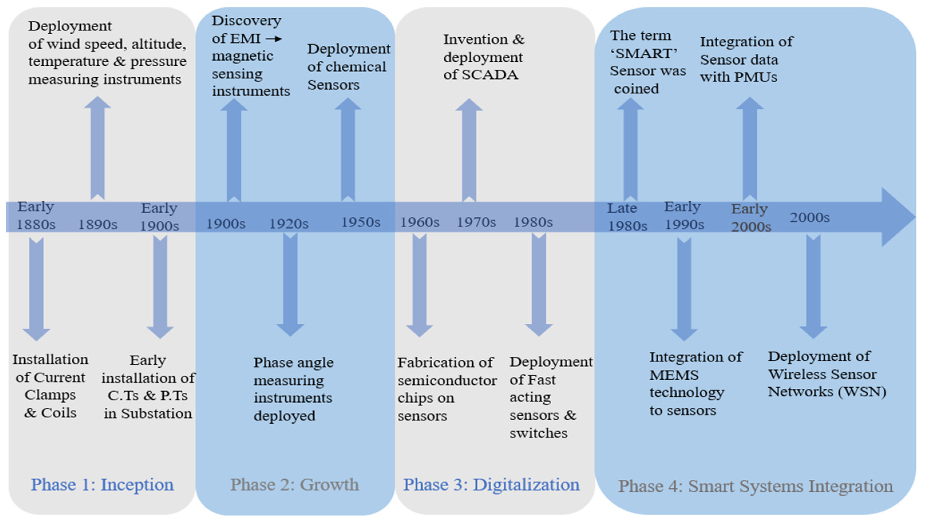
4.1. Pathway of Sensor Development in Transmission and Distribution Systems: From Yesterday to Today and Tomorrow

The timeline for the development of sensor technology in the power grid is depicted in Figure 3. The study of this timeline is essential not only to understand and appreciate the process of evolution of sensors to what it is today but also to take inspiration from it while building the smart sensors of tomorrow. This timeline as depicted in Figure 3 is elucidated in a detailed manner as follows. The entire timeline can be divided into four major phases. The first phase or the inception phase represents the early deployment of instruments to measure basic grid and atmospheric parameters. It starts with the mounting of basic and crude instruments to measure the current in the grid. This is because the current was recognized as a local parameter and its measurement was deemed necessary, especially during fault conditions to isolate and protect expensive grid equipment. In the early 1800s, current measurement was conducted with current clamps and coils. In the 1890s, instruments were deployed to record the atmospheric parameters that affected the operations of grid components. There are reports of the first remote sensing device, "radiosonde" [135], being deployed in power grids for the measurement of atmospheric parameters such as temperature, pressure, wind speed, altitude, and humidity. In the early 1900s, crude current measuring instruments developed into more sophisticated electromechanical systems such as current transformers and potential transformers. These instruments were bulky and were installed mostly on power transformers to measure the two key parameters of the power grid – the voltage and the current.
Phase 2, or the growth phase, resembles the period where the importance of measuring devices in the power grid was recognized, especially for monitoring and protective purposes. Researchers aimed at developing special devices, later defined as sensors, that could provide a response to indicate the presence of various parameters in the grid. Furthermore, various other grid parameters, apart from currents and voltages, were measured or detected by these devices. One of those parameters to be considered first was the phase angle. Phase angle measurements were conducted to get a clearer estimation of real and reactive power flows in the system. The discovery of electromagnetic induction in the early 1900s paved the way for the development of magnetic sensing instruments which were unique because of their non-invasive nature [98]. In addition, in the late 1950s, multiple technologies and principles of science were incorporated into the design of new sensors. This made the sensors versatile and enabled them to measure several other fault indicators such as temperature, acoustics, pressure, chemicals, and gas.
Phase 3 is referred to as digitalization, which resembles the period where system size, system speed and system integration were given greater importance by the researchers. Since the sensors not only measured the values under observation but were also capable of detecting small changes in them, it was realized that they could be used for fault detection purposes. Hence, it was the need of the hour to have sensors that could function faster and measure multiple components of the grid for fault detection. Developments in the semiconductor industry in the 1960s with the fabrication of system-on-chip devices were a breakthrough that paved way for high performance but low-powered and lightweight sensors that replaced the bulky and lossy measuring instruments on the power grid [63]. These features made it possible for the sensors to be installed remotely and increased the visibility of the grid components, especially those that were installed outside the substations. In the 1970s, the Supervisory Control and Data Acquisition system was invented and deployed in the power grid. This facilitated the deployment of monitoring instruments and sensors that had faster response times and that could initiate local protective actions such as the action of circuit breakers, reclosers, and isolators. However, these sensors had lower sampling rates that were insufficient in the detection of details of transient phenomena that occurred in mere milliseconds. To capture this underlying data for optimum asset utilization, fast acting sensors and switches were deployed in the late 1980s.
Phase 4 is the smart systems integration. It represents the current period where researchers are more focused on developing smart sensors that can enable pervasive sensing with system integration and realize system miniaturization. In the early 1990s, MEMS technology was integrated with sensors that improved their accuracy and sensitivity to detect multiple grid parameters. Next, the early 2000s saw the integration of sensors with phase measuring units and measuring units which enabled real-time monitoring with very high sampling rates. Furthermore, the sensor technology matured from the deployment of single sensing devices to its incorporation with SCADAs, PMUs, and MUs, constituting the wide area monitoring systems for complete, synchronized, and digital monitoring of various components of the power grid. Currently, power system operators demand SCADA- and PMU-based real time data to monitor the dynamic power flow of the grid. With the help of these real time grid parameters, responses to emergency, fault and failure events are swift, thereby improving power security. Therefore, SCADAs and PMUs form an integral part of the online dynamic security assessment (DSA) systems [136]. Real time and online system measurements obtained from them are used for system estimation and system modeling to perform power system security analysis. A range of various off-line applications such as validating system models, operations planning, diagnostics, and post-event analyses, etc. are also conducted with these measurements [137]. When this is combined with newer software developments, advanced machine learning based algorithms with improved computational capabilities, and matured fiber optic based wired or wireless communication technologies using Wi-Fi, LoRa, ZigBee, and NB-IOT, [65] advanced applications such as “faster than real-time” state estimation [18], predictive controls, and rapid contingency analyses are realized. This creates a pervasive sensing network architecture for the power grid as modeled in Figure 4. Furthermore, the sensor data from equipment monitoring is also integrated into control systems, and new control strategies are devised to deal with the risks of equipment failures, etc. For example, currently, advanced automation schemes such as fault location, isolation, and service restoration systems (FLISR) [138] are being deployed in distribution systems that are controlled in real time by SCADA. They provide support for the enabling of DERs and improve distribution automation with efficient fault localization.
The current trend in the modern-day sensor technology is the integration of multiple sensors and other connected devices to form wireless sensing networks (WSN). The deployment of WSNs in the transmission and distribution systems is unique since it is an advanced technology facilitating not only efficient data acquisition but also data transmission and data processing to provide complete real-time monitoring of the grid. WSNs enable pervasive sensing among the transmission and distribution system components for fault measurements as well as the continuous monitoring of power system components for state estimations and forecasting [3]. This pervasive sensing network framework in power systems is depicted in Figure 4. The figure clearly demarcates the three major layers that constitute WSNs [2] that are deployed in transmission and distribution systems. The first layer is the perception layer or the input layer. It consists of the deployment of multiple sensors on various components of the transmission and distribution system. These sensors are often referred to as input sensors or source sensor nodes. The sensor nodes can also contain a sensor module along with a processor module for data processing, a wireless communication module for data transmission, and an energy management module to supply power to the other modules [139]. These sensor nodes can be deployed remotely to acquire raw grid parameter values essential for monitoring individual grid components. These sensor nodes can form part of a bigger assembly of sensors constituting SCADAs, PMUs, and MUs, for time synchronized data acquisition. The raw grid parameter values acquired can be interfaced with hardware for processing or control purposes through remote terminal units and programmable logic controller devices. The second layer facilitates the transmission of the raw grid parameter data into the application layer for further processing. The network layer broadly consists of two networks for data transmission called the core networks and the access networks [140]. The core networks are responsible for the wired transmission of data, especially with the help of optical fiber as a network channel. Access networks enable data transmission through wireless communication systems. Various modern wireless communication technologies [141] such as Wi-Fi, LoRa, NB-IoT, ZigBee, and satellites can be employed here. The third layer is called the application layer. This layer constitutes several application infrastructures, middleware, and application systems like SCADA servers and SCADA dashboards, where the transmitted data is analyzed, generally by operator personnel. The grid parameter data can also be processed in the application layer for the detection of developing fault features for online transmission system monitoring and online distribution system monitoring or online individual equipment monitoring. Intelligent computing with machine learning techniques can be used to process the raw grid parameter data for fault classification and fault forecasting, leading to the predictive maintenance of the system. This in turn forms an outage management system [142] for the transmission and distribution system components. Hence, through this process, pervasive sensing with WSN is realized in transmission and distribution systems.
The future development of sensors must consider certain unique features of the future power grids and the upcoming smart grids. To transition into smart grids [143] in the future, the existing power grids must dynamically configure themselves in accordance with the demand side changes for which they require instantaneous and simultaneous data from multiple nodes on the power grid. This calls for advanced sensing structures that would provide the real-time information on the status of a multitude of parameters of the power grid. This real-time information is not only essential for controlling the direction of power flow and information about energy consumption and production but also helps in the prediction or at least faster remediation of sudden events such as device failures, demand drops, etc. and forms a big part of the distribution automation and outage management system. It is also required to help with the synchronization within the grid as well as outside the grid. This is conducted by employing smart sensors at multiple pivotal points on the grid constituting the wireless sensor network.
Currently, smart sensors are being developed by taking into consideration the above features so that they could be deployed in the upcoming power grids and smart grids. These smart sensors have features of high speed, high accuracy and high sensitivity for data sensing and data processing. They have multiple sensing capabilities and intelligent sensing capabilities such as self-identification, self-localization, self-awareness, self-diagnostics, self-calibration, and self-compensation [6,70]. The general model of a smart sensor [6] employed in smart grids essentially consists of four modules as depicted in Figure 5. The sensing module includes a set of sensors for data acquisition along with memory for data storage. The processing module includes an internal clock and an external time reference for synchronized data processing by means of A/D conversions and data processing algorithm-based microprocessors along with internal memory. It can also contain independent modules for signal processing at the edge such as signal conditioning modules, signal conversion modules and intelligent data processing algorithm modules. The network and communication module with a radio module for transmission and a switching module is used for data networking and communication to the master centers via wired (serial or ethernet) or wireless cellular networks through standard communication protocols. Finally, the battery management module consists of an energy source and switching module that powers the sensing, processing, and communication module. These advances in smart sensors lead to the evolution of advanced metering infrastructures and smart IoT devices that in the future could have the capability of addressing the variable and unpredictable load profiles and enable system-wide coordination and protection. Along with this, the greater deployment of distributed generation, the use of aggregated demand response for the deployment of microgrids and smart grids, greater customer participation in power markets with dynamic pricing, and the integration of electric vehicles, smart buildings, smart industries, etc. on a larger, commercial scale can be realized [144]. Thus, the smart sensors of the future hold tremendous potential not only in their development but also in the development and functionality of future smart grids.

4.2. Advances in Utility Level and Consumer Level Grids with Modern Day Sensor Technology

Modern-day sensor technology has certain technical ramifications in the utility level and consumer level grid connections. From the review, it can be inferred that at the utility grid level, substantial advancements have been realized in the past decade to upgrade the sensors used on transmission and distribution systems. Firstly, the deployment of sensors has been fast paced with an extensive reach, covering almost the entire utility grid. Sensors have developed from just directly measuring the traditional grid parameters such as values of voltages and currents to sensing more complex grid features such as the electromagnetic signatures, material properties, acoustics, and frequency of operations to estimate more accurate values of the sensed parameters. Second, modern-day sensor technology has predictive controls enabling the integration of automated and intelligent models and instrumentation. Sensor technology has matured from the deployment of single sensing devices on the power grid components to its incorporation with SCADAs, PMUs, MUs, etc. constituting the wide area monitoring systems for complete, synchronized, and digital monitoring of multiple components of the power grid. The incorporation of advanced communication protocols such as wired fiber optics communications and wireless communications with Wi-Fi, LoRa, ZigBee, NB-IOT, etc., have helped to improve the efficiency and speed of data transmission... Finally, the incorporation of machine learning and IoT into the maturing sensor technology is another attractive feature that not only improves the sensing process but also efficiently integrates the sensed raw grid parameter data for synchronized data collection and transmission with artificial intelligence and cognitive data analysis at the edge, thereby reducing outage management time and boosting the holistic asset utilization of the power grid [145,146].
However, at the consumer level, transformation of the traditional sensors and the electric meters with advanced sensor technology is still latent but will be coming in a few years. The pace of deployment of modern-day sensors has been slow and their reach is very limited to a particular area for a particular functioning. For smart meters and meter data management systems, MDMS installed at certain consumer-side loads can provide data on energy usage, power quality and economic metrics with remote communication facilities to the grid operator. There is still a requirement for pervasive and smart sensing techniques that will enable customized scheduling, reduced billing, demand response, and the support of new controlling strategies to accommodate the needs of smart homes and smart buildings [23]. This is also required for electrical market analysis to facilitate planning, load forecasting, and structuring of engineering designs and standards [147]. Furthermore, there is a requirement for enhancing customer service and customer experience by competing energy service companies. Various customer centric applications such as reports on charging-discharging time and time-of-use rates [147], especially for bigger loads like electric vehicles, can be provided through appropriate embedded sensors. Smart sensors and advanced metering instruments (AMI) can also help increase consumers’ participation in the energy market and energy management processes. The modern-day sensor technology from the point of view of the utility level grid and consumer level grid has been depicted in Figure 6.

4.3. Advances in Transmission and Distribution Systems with Modern Day Sensor Technology

Modern sensor technology can prove itself instrumental in remodeling the traditional transmission and distribution systems to cope with the impending developments in the near future. Some of the significant developments that can be realized in the existing transmission and distribution systems by their integration with modern-day sensor technology are discussed below and are tabulated in Table 3.
Modern-day sensor technology has the ability to bring significant developments in the existing structure and functionality of transmission systems. The current operations of the transmission systems are mostly based on operator-based controls. To realize autonomy, synchronicity, efficiency, and faster response of the transmission system in the future, there is a need to replace the operator dependent controls with automatic controls. The modern-day sensor technology can form an important part of this automation system by enabling the detection and measurement of physical or grid parameter variations which could provide essential information to the control system to take necessary actions without being dependent on the expertise of operator personnel [148]. Automatic controls can also improve the existing islanding and anti-islanding issues in microgrids and configure switchable networks to relieve congestion issues and improve the transmission capacity of the system. Along with this, modern-day sensor technology can help monitor the bidirectional flow of power when the traditional transmission systems evolve into smart grids in the future. Furthermore, the incorporation of machine learning and IOT-based real time condition monitoring and predictive maintenance of the entire system along with strong cybersecurity protocols can vastly reduce the vulnerability to faults, destabilizing issues, and cybersecurity threats [145,149]. The current transmission system is predominantly equipped with SCADA systems with integrated PMU-based wireless sensing networks for real time monitoring. This situation is expected to be improved with the incorporation of new and forthcoming developments in sensor technology that will allow for real time, time-synchronized monitoring, and adaptive transmission line measuring instrument sensors for multi-level coordination of the entire transmission system. ‘Faster-than-real-time’ [142] monitoring and predictive maintenance will help build sturdier transmission systems and will enable ‘on-need-basis’ dispatch and re-dispatch of generation. The inclusion of optimized energy storage systems in wireless sensor networks will reduce the dependency on the main grid, thereby not affecting the normal operation of the transmission system due to the failure of sensors or a wireless sensor network [150,151].
The modern-day sensor technology has also brought significant developments to the existing structure and functionality of distribution systems. The current structure of the distribution system is mostly ‘floating on the transmission line’ [142] with limited monitoring and controls that are restricted to the substation. Furthermore, the topology of the distribution systems is mostly a radial structure that supports power flow in a single direction. The coming age of smart grids calls for the facilitation of bidirectional power and distribution system automation. Distribution system automation is essential for the real-time adjustment of the system in response to the dynamic changes in loads and other fault conditions without operator intervention. This automation with advanced distribution management systems for automatic controls and monitoring can be brought about with the help of modern-day sensor technologies. Autonomous controls can be realized by installing sensors and PMUs and MUs-based wireless sensing networks outside the substation along the entire length of the distribution system. The current monitoring of the distribution system is mostly restricted to the substation. However, with the implementation of modern sensor technology, on-site, remote, and real-time distribution system asset monitoring can be realized [152]. This will strongly isolate the transmission system faults from dissipating into the distribution system, improving the reach of protection and the distribution system capacity. Furthermore, as discussed above for transmission lines, modern sensor technology could also improve the resiliency of the distribution systems by facilitating real time, time-synchronized condition monitoring and predictive maintenance [153] to cope with vulnerabilities of distribution systems to such things as faults, destabilizing issues, and cybersecurity threats. Hence, the development of transmission and distribution systems and the development of modern-day sensor technology go hand in hand. Thus, the study of the latest developments in sensor technology is a precursor to realize the necessary developments in the power grid.

5. Key Challenges and Future Research Directions

The current topology of sensors in transmission and distribution systems face certain unique challenges during their deployment and functioning in transmission and distribution systems. Knowledge about these challenges could help open new avenues of research in the future. The key challenges discussed here can be addressed by the future generation of researchers to accommodate the matured sensor technology by improving it to fit into the upcoming era of smart grids. Some of the key areas and issues are described below.

5.1. Credibility of Data Acquisition

Sensors facilitate the raw data acquisition of grid parameters through the sensing of various grid components. However, during these acquisitions, the input sensors, especially the source sensor nodes in wireless sensing networks face several issues. First, there is poor management and no security at the input level, which makes the sensor nodes vulnerable to hackers and attackers [153]. Hence, privacy at the input sensing level must be ascertained to maintain the credibility and quality of the sensed raw data. Second, even though the synchronicity among input sensor nodes for wireless sensor networks are maintained through clocks and timers, identity management of each node is still not achieved. This makes the identification and location of faulty nodes in big wireless sensing networks difficult. The identification and naming of sensor nodes is essential since it would help in declaring their availability for efficient utilization of each sensor node, especially during different modes of operations. For example, at any given point in time, some nodes might be in an ACTIVE state, but others might be in SYNCH or SLEEP states, and providing specific addresses to different input sensor nodes would make their differentiation easier [154]. It would also help with the addition of newer sensor nodes into the system that will increase their scalability. Here, scalability means the ability to integrate new sensors to the wireless sensing networks for its expansion in the future. Thirdly, the parameter update policy [3] of the acquired raw grid parameters is not standardized according to the grid conditions. For example, the temporal resolution of electrical parameters during transient grid conditions is supposed to be lower than that in normal grid conditions. Hence, the grid parameters should be updated according to the changing grid conditions. This is essential in capturing the complete profile with all the features of the fault parameters. Finally, there is no accountability for the losses in sensors. Depending on their characteristics, different sensors can have different losses in them, such as magnetization losses in current transformer-based sensors, thermal runaways in optical sensors, the high sensitivity of magnetic sensors, etc. These losses, which are specific to the type of the sensors deployed, should be accounted for while processing the acquired raw grid parameter data. To summarize, the research directions should be focused on addressing the challenges of sensor node identification, heterogeneity, losses, and synchronicity. Ref. [155] suggests dealing with these issues by designing lightweight protocols to facilitate identity address allocation, the detection of address collision and address duplication, address recycling, address translation, and address auto-configuration for scalable and seamless ubiquitous connectivity among sensor nodes.

5.2. Big Data & Data Deluge

With the increase in the number of sensors and wireless sensing networks for long- term and continuous monitoring of grid parameters as well as the need for substantial input data for employing machine learning and deep learning algorithms for processing the acquired raw grid parameter data, an enormous amount of data is being sensed by the input sensor nodes. This makes other functions such as data transmission, data storage, and data processing very challenging, leading to data deluge [2]. Furthermore, deep network structures with complex algorithms and large storage memory will be required to extrapolate the unstructured big data and maintain its quality. Big data also leads to an increase in hardware for storage and processing as well as the overall cost of the entire network, debarring the concept of system miniaturization, which is the need of the hour, especially while creating an entire IoT system support for grid computations. Ref. [3] suggests data preprocessing at the edge level to reduce the size of data near the source, thereby reducing the size and power required for data transportation, data storage, and data processing. This also suggests the use of distributed file systems, NoSQL databases, and data processing tools in power grid computations such as Hadoop, Storm, Spark, and Grid Gain in order to avoid the issue of data deluge.

5.3. Heterogeneity Issues

There are multitude of grid parameters that are required to be sensed for complete grid monitoring such as current, voltage, temperature, humidity, pressure, chemical, gas, and vibration. This calls for a heterogenous mixture of sensors that can sense such diverse and heterogenous data. However, such heterogenous data leads to challenges in data fusion which is an essential procedure while data preprocessing. Inefficient data fusion might lead to the loss of essential fault parameter features. Furthermore, the raw data can be captured in multiple forms such as waveform, values, images, videos, etc. This makes their integration with each other cumbersome and time-consuming. Due to the heterogeneity among different types of sensors, it is also difficult to build a heterogenous sensor network since different sensors will have different accuracy and different losses under the same grid conditions [5]. For example, some sensors like Rogowski coils or GMO sensors may not work well in high voltage networks as efficiently as optical sensors, etc. Furthermore, the output of different sensors varies under the same grid conditions. For example, some sensors might have faster responses than others, and some might have linear whereas others might have non-linear responses for the same grid parameters.

5.4. Storage and Power Optimization Issues

As discussed above, with big data and large heterogeneity among sensors, there is a need for larger memory devices for storage of the acquired raw grid parameter data. Different storage systems are required at multiple levels such as sensing levels in the input layer, communication level, and application level for data processing. Furthermore, storage systems are required to be secured from cyber-attacks. They are also required to be expandable or scalable in case new sensor integration occurs later in the future. Energy storage [156] is also an issue since the integration of microcontrollers, and communication and computation modules, along with multiple sensors call for more power utilization. Furthermore, most devices are deployed in remote environments and regular battery charging and re-charging can be demanding and expensive. Power optimization [18] is being conducted through energy harvesting, power converters, power latency tradeoffs, etc. Optimized embedded systems are under research and are a promising area. Devising energy efficient protocols and mechanisms [72] that enable devices or sensors to self-generate, self-harvest, recycle, and store energy is another research direction to address the issue of storage and power requirements.

5.5. Security Issues

The overall security of the entire sensor system is complex and is required in every layer, especially the network and the application layer. This is because cyber-attack can lead to stealing and loss of data from the cloud, manipulation of computational results, etc. These results could be as catastrophic as the collapse of the entire grid. Thus, breach or loss of data could affect the power security and stability of the power grid [157]. Ref. [3] suggests resolving the issue of cybersecurity with blockchain technology where all the parameters can be retained in blockchains and accessed through blockchain protocols [158]. Another option could be the design of advanced and secured protocols with authentication and authorization as methods for access and control [73].

5.6. Scalability Issues

The complete integration of advanced sensing technologies with every component of the power grid is difficult to realize. This is because synchronization becomes an issue with heterogeneity among power grid components. The power grid is a huge entity with a multitude of parameters of diverse nature that needs to be monitored and controlled. There have also been deployment issues since replacing the traditional metering and measuring systems over the entire length of the power system is capital-, labor-, and knowledge-intensive in nature. Furthermore, the full integration of multiple sensing technologies is difficult, owing to the diverse nature of power sources and the surrounding environment. Thus, the development of a single sensing technology or a standard protocol is difficult if not impossible to implement, especially with the dynamic nature of the technology where advanced components, control methods, and interfaces are still under rapid development [147]. One such attractive technology is called FLEXITRANSTORE which is an Integrated Platform for Increased FLEXIbility in smart TRANSmission grids with STORage Entities and large penetration of Renewable Energy Sources [159]. Its goal is to improve the deployment of future smart grids while addressing their scalability and replicability issues.
Thus, some of the key challenges faced by the current transmission and distribution system topologies have been described above. Researchers working on the future expansion of the power grid and its transformation into smart grids can take inspiration from the above key challenges. Furthermore, researchers interested in condition health monitoring and predictive maintenance of power systems can take their future research insights from this review. Finally, problem statements for popular research topics such as power and storage optimization, big data, and cybersecurity can be found in the key challenges described above.

6. Conclusions

The latest developments in sensing technologies in transmission and distribution systems have been reviewed in this paper. The newest literature pertaining to modern-day sensors and their requirement on major power system components has been studied, compared, and reported in the paper. Furthermore, the paper presents a timeline for the development of sensor technology in transmission and distribution systems. The paper also gives the utility grid and consumer grid’s point of view on sensor technology. Finally, the paper charts out the beneficial impacts of sensor technology on power systems, its future impacts, as well as some of its key issues as topics of interest for future researchers. It can be concluded from the above review that sensing technologies are fast becoming an important component for the control and monitoring of the power grid. The main goal of modern sensing technology has evolved from the collection of grid parameter values for human interpretation to the complete transformation of the sensed data to provide critical real time information, thereby enhancing the other key areas of the power grid, such as accurate fault detection and localization, condition monitoring, outage management, fault forecasting, and predictive maintenance. These advances help in the development of traditional electrical grid by enabling the penetration of distributed and renewable energy sources, the addition of power electronic devices, and nonlinear loads and its transformation into smart grids in the future. Hence, it is of utmost importance for the government and power companies to promote the research and development of sensing technologies as well as to facilitate their deployment to boost the overall asset utilization of the modern power grid.

Author Contributions

Conceptualization, A.S. and P.W.P.; writing—original draft preparation, A.S.; writing—review and editing, E.A., A.M. and P.W.P.; visualization, A.S. and P.W.P.; supervision, P.W.P. All authors have read and agreed to the published version of the manuscript.

Funding

This research received no external funding.

Institutional Review Board Statement

Not applicable.

Informed Consent Statement

Not applicable.

Data Availability Statement

Not applicable.

Conflicts of Interest

The authors declare that they have no conflicts of interest.

References

  1. De Almeida, L.F.F.; Dos Santos, J.R.; Pereira, L.A.M.; Sodre, A.C.; Mendes, L.L.; Rodrigues, J.J.P.C.; Rabelo, R.A.L.; Alberti, A.M. Control Networks and Smart Grid Teleprotection: Key Aspects, Technologies, Protocols, and Case-Studies. IEEE Access 2020, 8, 174049–174079. [Google Scholar] [CrossRef]
  2. Liu, J.; Zhao, Z.; Ji, J.; Hu, M. Research and application of wireless sensor network technology in power transmission and distribution system. Intell. Converg. Netw. 2020, 1, 199–220. [Google Scholar] [CrossRef]
  3. Pong, P.W.; Annaswamy, A.M.; Kroposki, B.; Zhang, Y.; Rajagopal, R.; Zussman, G.; Poor, H.V. Cyber-enabled grids: Shaping future energy systems. Adv. Appl. Energy 2021, 1, 100003. [Google Scholar] [CrossRef]
  4. Morello, R.; Mukhopadhyay, S.C.; Liu, Z.; Slomovitz, D.; Samantaray, S.R. Advances on Sensing Technologies for Smart Cities and Power Grids: A Review. IEEE Sens. J. 2017, 17, 7596–7610. [Google Scholar] [CrossRef]
  5. Sensor Technologies for a Smart Transmission System; EPRI Technical Reports NSAC; Electric Power Re-search Institute: Palo Alto, CA, USA, 2009.
  6. Huo, Y.; Prasad, G.; Lampe, L.; Leung, V.C.M. Advanced Smart Grid Monitoring: Intelligent Cable Diagnostics using Neural Networks. In Proceedings of the 2020 IEEE International Symposium on Power Line Communications and its Applications (ISPLC), Málaga, Spain, 11–13 May 2020; pp. 1–6. [Google Scholar] [CrossRef]
  7. Ripka, P. Electric current sensors: A review. Meas. Sci. Technol. 2010, 21, 112001. [Google Scholar] [CrossRef] [Green Version]
  8. Wetula, A.; Bień, A.; Parekh, M. New Sensor for Medium- and High-Voltage Measurement. Energies 2021, 14, 4654. [Google Scholar] [CrossRef]
  9. Chen, W.; Wang, J.; Wan, F.; Wang, P. Review of optical fibre sensors for electrical equipment characteristic state parameters detection. High Volt. 2019, 4, 271–281. [Google Scholar] [CrossRef]
  10. Peng, J.; Jia, S.; Bian, J.; Zhang, S.; Liu, J.; Zhou, X. Recent Progress on Electromagnetic Field Measurement Based on Optical Sensors. Sensors 2019, 19, 2860. [Google Scholar] [CrossRef] [Green Version]
  11. Wu, T.; Liu, G.; Fu, S.; Xing, F. Recent Progress of Fiber-Optic Sensors for the Structural Health Monitoring of Civil Infra-structure. Sensors 2020, 20, 4517. [Google Scholar] [CrossRef]
  12. Xie, K.; Zhao, Y.; Zhang, H.; Zhao, Z.; Lu, Z.; Chai, Q.; Zhang, J. Practice of optical fiber sensing technologies in power transmission lines and towers. In Proceedings of the 2018 International Conference on Power System Technology (POWERCON), Guangzhou, China, 6–8 November 2018; pp. 3912–3918. [Google Scholar] [CrossRef]
  13. Hamed, M.S.; Dadashi, H.I. Survey of different sensors employed for the power transformer monitoring. IETSci. Meas.Technol. 2020, 14, 1–8. [Google Scholar] [CrossRef]
  14. Sun, C.; Ohodnicki, P.R.; Stewart, E.M. Chemical Sensing Strategies for Real-Time Monitoring of Transformer Oil: A Review. IEEE Sens. J. 2017, 17, 5786–5806. [Google Scholar] [CrossRef]
  15. Bustamante, S.; Mario, M.; Alberto, A.; Pablo, C.; Alberto, L.; Raquel, M. Dissolved Gas Analysis Equipment for Online Monitoring of Transformer Oil: A Review. Sensors 2019, 19, 4057. [Google Scholar] [CrossRef] [PubMed] [Green Version]
  16. Youssef, M.M.; Ibrahim, A.R.; Hussein, D.; Moustafa, Z.M.M. An Overview on Condition Monitoring & Health Assessment Techniques for Distribution Transformers. In Proceedings of the 2022 6th International Conference on Green Energy and Applications (ICGEA), Singapore, 4–6 March 2022; pp. 187–192. [Google Scholar]
  17. Tran, Q.T.; Davies, K.; Roose, L.; Wiriyakitikun, P.; Janjampop, J.; Sanseverino, E.R.; Zizzo, G. A Review of Health Assessment Techniques for Distribution Transformers in Smart Distribution Grids. Appl. Sci. 2020, 10, 8115. [Google Scholar] [CrossRef]
  18. Khawaja, A.H.; Huang, Q.; Khan, Z.H. Monitoring of Overhead Transmission Lines: A Review from the Perspective of Con-tactless Technologies. Sens. Imaging 2017, 18, 24. [Google Scholar] [CrossRef]
  19. Zhao, L.; Zhang, T.; Huang, X.; Zhang, Y.; Liu, W. A structural health monitoring system of the overhead transmission line conductor. IETSci. Meas. Technol. 2022, 16, 28–39. [Google Scholar] [CrossRef]
  20. Zainuddin, N.M.; Rahman, A.; Kadir, A.; Ali, N.; Ali, N.H.; Osman, Z.; Mansor, M.; Ariffin, M.M.; Rahman, A.S.A.; Nasir, M. Review of Thermal Stress and Condition Monitoring Technologies for Overhead Transmission Lines: Issues and Challenges. IEEE Access 2020, 8, 120053–120081. [Google Scholar] [CrossRef]
  21. Orton, H. History of underground power cables. IEEE Electr. Insul. Mag. 2013, 29, 52–57. [Google Scholar] [CrossRef]
  22. Kulkarni, S.; Santoso, S.; Short, T.A. Incipient Fault Location Algorithm for Underground Cables. IEEE Trans. Smart Grid 2014, 5, 1165–1174. [Google Scholar] [CrossRef]
  23. Fadel, E.; Gungor, V.; Nassef, L.; Akkari, N.; Malik, M.A.; Almasri, S.; Akyildiz, I.F. A survey on wireless sensor networks for smart grid. Comput. Commun. 2015, 71, 22–33. [Google Scholar] [CrossRef]
  24. Leoni, J.L.; Nogueira, J.M.S.; Campos, M.F.M.; Macedo, D.F.; Salvador, E.M.; Mota, V.F.S.; Resende, D.B.; Silva, V.F.; Correia, L.H.A.; Vieira, L.H.A.; et al. Real-time monitoring of transmission lines using wireless sensor networks. In Proceedings of the IEEE PES Transmission & Distribution Conference and Exposition—Latin America, Medellin, Colombia, 10–13 September 2014; pp. 1–6. [Google Scholar]
  25. Takriti, M.; Boussaada, Z.; Sansa, I.; Curea, O.; Bellaaj, N.M. Wireless Sensors Networks Applications For Micro-Grids Man-agement: State of Art. In Proceedings of the 6th IEEE International Energy Conference (ENERGYCon), Gammarth, Tunisia, 28 September–1 October 2020; pp. 1058–1061. [Google Scholar]
  26. Kayastha, N.; Niyato, D.; Hossain, E.; Han, Z. Smart grid sensor data collection, communication, and networking: A tutorial. Wirel. Commun. Mob.Comput. 2014, 14, 1055–1087. [Google Scholar] [CrossRef]
  27. Song, E.Y.; FitzPatrick, G.J.; Lee, K.B. Smart Sensors and Standard-Based Interoperability in Smart Grids. IEEE Sens. J. 2017, 17, 7723–7730. [Google Scholar] [CrossRef] [PubMed]
  28. Sijakovic, N.; Terzic, A.; Fotis, G.; Mentis, I.; Zafeiropoulou, M.; Maris, T.I.; Zoulias, E.; Elias, C.; Ristic, V.; Vita, V. Active System Management Approach for Flexibility Services to the Greek Transmission and Distribution System. Energies 2022, 15, 6134. [Google Scholar] [CrossRef]
  29. Zafeiropoulou, M.; Mentis, I.; Sijakovic, N.; Terzic, A.; Fotis, G.; Maris, T.I.; Vita, V.; Zoulias, E.; Ristic, V.; Ekonomou, L. Forecasting Transmission and Distribution System Flexibility Needs for Severe Weather Condition Resilience and Outage Management. Appl. Sci. 2022, 12, 7334. [Google Scholar] [CrossRef]
  30. Jena, P.K.; Ghosh, S.; Koley, E. Identification of Optimal Sensor Location Based on Trade-Off Approach to Improve Resiliency of Electricity Market in Smart Grid. IEEE Sens. J. 2021, 21, 17271–17281. [Google Scholar] [CrossRef]
  31. Song, E.Y.; FitzPatrick, G.J.; Lee, K.B.; Gopstein, A.M.; Boynton, P.A. Interoperability testbed for smart sensors in smart grids. In Proceedings of the IEEE Power & Energy Society Innovative Smart Grid Technologies Conference, Washington, DC, USA, 19–22 February 2018; pp. 1–5. [Google Scholar]
  32. Islam, T.; Mukhopadhyay, S.C.; Suryadevara, N.K. Smart Sensors and Internet of Things: A Postgraduate Paper. IEEE Sens. J. 2016, 17, 577–584. [Google Scholar] [CrossRef]
  33. Lapierre, J.; Hoekzema, M.; Stock, M.; Merrill, C.; Thangaraj, S.C. Earth Networks Lightning Network and Dangerous Thun-derstorm Alerts. In Proceedings of the 11th Asia-Pacific International Conference on Lightning, Hong Kong, China, 12–14 June 2019; pp. 1–5. [Google Scholar]
  34. Wali, M.U.; Ali, M.S.Z.; Afzal, M.; Khawaja, A.H. Condition Monitoring of Insulators for Ageing Detection Via Magnetic Field Measurements. In Proceedings of the 2019 International Conference on Electrical, Communication, and Computer Engineering (ICECCE), Swat, Pakistan, 24–25 July 2019; pp. 1–6. [Google Scholar] [CrossRef]
  35. Huang, Z.; Zhu, T. Real-Time Data and Energy Management in Microgrids. In Proceedings of the 2016 IEEE Real-Time Systems Symposium (RTSS), Porto, Portugal, 29 November–2 December 2016; pp. 79–88. [Google Scholar] [CrossRef]
  36. Syed, D.; Zainab, A.; Ghrayeb, A.; Refaat, S.S.; Abu-Rub, H.; Bouhali, O. Smart Grid Big Data Analytics: Survey of Technologies, Techniques, and Applications. IEEE Access 2020, 9, 59564–59585. [Google Scholar] [CrossRef]
  37. Song, E.Y.; Fitz Patrick, G.J.; Lee, K.B.; Griffor, E. A Methodology for Modeling Interoperability of Smart Sensors in Smart Grids. IEEE Trans. Smart Grid 2021, 13, 555–563. [Google Scholar] [CrossRef]
  38. Swain, A.; Dash, S.S.; Bastia, S.; Bagarty, D.P.; Behera, S. Source Side Control Analysis of An AC Microgrid Fed with Hybrid Renewable Distributed Energy Sources. In Proceedings of the 2020 3rd International Conference on Energy, Power and Environment: Towards Clean Energy Technologies, Shillong, Meghalaya, India, 5–7 March 2021; pp. 1–5. [Google Scholar] [CrossRef]
  39. Soto, E.A.; Bosman, L.B.; Wollega, E.; Leon-Salas, W.D. Analysis of Grid Disturbances Caused by Massive Integration of Utility Level Solar Power Systems. Eng 2022, 3, 236–253. [Google Scholar] [CrossRef]
  40. Basso, T.S. System Impacts from Interconnection of Distributed Resources: Current Status and Identification of Needs for Further Development; National Renewable Energy Lab.(NREL): Golden, CO, USA, 2009. [Google Scholar] [CrossRef] [Green Version]
  41. Tavakoli, A.; Saha, S.; Arif, M.T.; Haque, E.; Mendis, N.; Oo, A.M. Impacts of grid integration of solar PV and electric vehicle on grid stability, power quality and energy economics: A review. IET Energy Syst. Integr. 2020, 2, 243–260. [Google Scholar] [CrossRef]
  42. Johansen, P. The ultimate grid sensor measuring three phase currents from the outside of a three phase cable and utilizing advanced power system analysis. In Proceedings of the 2018 International Conference on Power System Technology (POWERCON), Guangzhou, China, 6–8 November 2018; pp. 3948–3953. [Google Scholar] [CrossRef]
  43. Quadrennial Technology Review 2015: An Assessment of Energy Technologies and Research Opportunities. Chapter 3: Enabling Modernization of the Electric Power System, U.S. Department of Energy. Available online: https://www.energy.gov/sites/prod/files/2017/03/f34/qtr-2015-chapter3.pdf (accessed on 22 April 2022).
  44. Srivastava, D.; Tripathi, M.M. Transformer Health Monitoring System Using Internet of Things. In Proceedings of the 2018 2nd IEEE International Conference on Power Electronics, Intelligent Control and Energy Systems (ICPEICES), Delhi, India, 22–24 October 2018; pp. 903–908. [Google Scholar] [CrossRef]
  45. Sim, H.J.; Harris, D.L. Current practices on power transformer monitoring and controls for smart grid applications. In Proceedings of the 2011 IEEE Power and Energy Society General Meeting, Detroit, MI, USA, 24–28 July 2011; pp. 1–5. [Google Scholar] [CrossRef]
  46. Dennison, J.C.; Trout, J.M. Transformer oil DGA monitoring technology study 2015. In Proceedings of the 2016 IEEE/PES Transmission and Distribution Conference and Exposition (T&D), Dallas, TX, USA, 3–5 May 2016; pp. 1–5. [Google Scholar]
  47. Cennamo, N.; Zeni, L.; Maria, L.D.; Agostino, C.D.; Pesavento, M. Optical chemical sensor for oil-filled power transformer. In Proceedings of the 2014 Fotonica AEIT Italian Conference on Photonics Technologies, Naples, Italy, 12–14 May 2014; pp. 1–3. [Google Scholar]
  48. Rutledge, C. Monitoring Gas Generation in Transformers. In Proceedings of the IEEE/PES Transmission and Distribution Conference and Ex-position (T&D), Denver, CO, USA, 16–19 April 2018; pp. 1–9. [Google Scholar]
  49. Minglei, S.; Xiang, L.; Changping, Z.; Jiahua, Z. Gas concentration detection using ultrasonic based on wireless sensor net-works. In Proceedings of the 2nd International Conference on Information Science and Engineering, Hangzhou, China, 4–6 December; pp. 2101–2106.
  50. Singh, K.; Minto, C.; Godfrey, A. OptaSense distributed acoustic sensing (DAS) system for the power network—Integrated SMART-sensing real time monitoring. In Proceedings of the IET International Conference on Resilience of Transmission and Distribution Networks (RTDN), Birmingham, UK, 22–24 September 2015; pp. 1–4. [Google Scholar]
  51. Nicoară, T.; Marinescu, A.; Pătru, I. Partial discharge diagnostics in power and instrument transformer based on acoustic emission method. In Proceedings of the International Conference on Applied and Theoretical Electricity (ICATE), Craiova, Romania, 6–8 October 2016; pp. 1–6. [Google Scholar]
  52. Ping, Z.C.; Liang, H.Y.; Peng, W.; Wei, R.; Qingyi, S.; Minglei, S.; Qinbang, H. The design of wireless monitoring systems based on ultrasonic method for metro power transmission and distribution. In Proceedings of the 2011 International Conference on Electronics, Communications and Control (ICECC), Ningbo, China, 9–11 September 2011; pp. 2351–2354. [Google Scholar] [CrossRef]
  53. Tan, H.; Chen, X.; Ma, J.; Tan, Y. A design of substation temperature online monitoring system based on SAW temperature sensor. In Proceedings of the IEEE International Conference on High Voltage Engineering and Application (ICHVE), Chengdu, China, 19–22 September 2016; pp. 1–4. [Google Scholar] [CrossRef]
  54. Haque, N.; Ittiarah, J.V.; Gangopadhyay, T.K.; Chakravorti, S. Temperature monitoring of power transformer using fiber-optic sensor. In Proceedings of the 1st Conference on Power, Dielectric and Energy Management at NERIST (ICPDEN), Arunachal Pradesh, India, 10–11 January 2015; pp. 1–5. [Google Scholar]
  55. Liu, Y.; Li, H.; Wang, J.; Fan, X. Research on 35 kV Transformer Distributed Temperature Sensing System Based on Optical Fiber Sensing. In Proceedings of the IEEE 4th International Conference on Frontiers of Sensors Technologies (ICFST), Shanghai, China, 6–9 November 2020; pp. 26–29. [Google Scholar] [CrossRef]
  56. Severo, J.; Fantin, K.V.; Alves, M.E.G. Step Up Transformer Online Monitoring Experience in Tucuruí Power Plant. In Proceedings of the 2010 IEEE/PES Transmission and Distribution Conference and Exposition: Latin America (T&D-LA), Sao Paulo, Brazil, 8–10 November 2010; pp. 388–393. [Google Scholar]
  57. Ziegler, S.; Woodward, R.C.; Borle, L.J. Current Sensing Techniques: A Review. IEEE Sens. J. 2009, 9, 354–376. [Google Scholar] [CrossRef]
  58. Sims, J. The Difference Between Power and Distribution Transformers. Available online: https://www.critterguard.org/blogs/articles/the-difference-between-power-and-distribution-transformers (accessed on 19 September 2022).
  59. Jardini, J.; Schmidt, H.; Tahan, C.M.; De Oliveira, C.C.; Ahn, S.U. Distribution transformer loss of life evaluation: A novel approach based on daily load profiles. IEEE Trans. Power Deliv. 2000, 15, 361–366. [Google Scholar] [CrossRef] [Green Version]
  60. Raghavan, A.; Kiesel, P.; Teepe, M.; Cheng, F.; Chen, Q.; Karin, T.; Jung, D.; Mostafavi, S.; Smith, M.; Stinson, R.; et al. Low-Cost Embedded Optical Sensing Systems For Distribution Transformer Monitoring. IEEE Trans. Power Deliv. 2020, 36, 1007–1014. [Google Scholar] [CrossRef]
  61. Agah, S.M.; Abyaneh, H.A. Effect of Modeling Non-Normality and Stochastic Dependence of Variables on Distribution Transformer Loss of Life Inference. IEEE Trans. Power Deliv. 2012, 27, 1700–1709. [Google Scholar] [CrossRef]
  62. Lu, P.; Buric, M.P.; Byerly, K.; Moon, S.R.; Nazmunnahar, M.; Simizu, S.; Leary, A.M.; Beddingfield, R.B.; Sun, C.; Zandhuis, P.; et al. Real-Time Monitoring of Temperature Rises of Energized Transformer Cores With Dis-tributed Optical Fiber Sensors. IEEE Trans. Power Deliv. 2019, 34, 1588–1598. [Google Scholar] [CrossRef]
  63. Pawar, R.R.; Deosarkar, S.B. Health condition monitoring system for distribution transformer using Internet of Things (IoT). In Proceedings of the 2017 international conference on computing methodologies and communication (ICCMC), Erode, India, 18–19 July 2017; pp. 117–122. [Google Scholar] [CrossRef]
  64. Atkinson, G.; Thottan, M. Leveraging advanced metering infrastructure for distribution grid asset management. In Proceedings of the 2014 IEEE Conference on Computer Communications Workshops (INFOCOM WKSHPS), Toronto, ON, Canada, 27 April–2 May 2014; pp. 670–675. [Google Scholar] [CrossRef]
  65. Shil, P.; Anderson, T. Distribution Transformer Health Monitoring and Predictive Asset Maintenance. In Proceedings of the 2019 SAS Global Forum, Dallas, TX, USA, 28 April–1 May 2019; pp. 1–11. [Google Scholar]
  66. Sun, L.; Tong, L.; Huang, L.; Tang, Y.; Hu, C.; Li, X.; Fan, X.; He, L. An effective health index calculation of 10 kV distribution transformer using fuzzy set theory and nonlinear fuzzy AHP. In Emerging Developments in the Power and Energy Industry; CRC Press: Boca Raton, FL, USA, 2019; pp. 452–458. [Google Scholar] [CrossRef]
  67. Wang, N.; Zhao, F. An Assessment of the Condition of Distribution Network Equipment Based on Large Data Fuzzy Decision-Making. Energies 2020, 13, 197. [Google Scholar] [CrossRef]
  68. Roland, U.; Omorogiuwa, D. Artificial Neural Network Approach to Distribution Transformers Maintenance. Int. J. Sci. Res. Eng. Technol. 2015, 4, 62–70. [Google Scholar]
  69. Dong, X.; Liu, Y.; Kong, X.; Liu, H.; Ren, Z. Degradation Evaluation of 35 kV XLPE Cable Based on Magnetic Field Distribution Characteristics. In Proceedings of the 2020 IEEE 3rd International Conference on Dielectrics (ICD), Valencia, Spain, 5–31 July 2020; pp. 5–8. [Google Scholar] [CrossRef]
  70. Khawaja, A.H.; Huang, Q. Estimating Sag and Wind-Induced Motion of Overhead Power Lines With Current and Magnet-ic-Flux Density Measurements. IEEE Trans. Instrum. Meas. 2017, 66, 897–909. [Google Scholar] [CrossRef]
  71. Jones, D.; Golightly, I.; Roberts, J.; Usher, K. Modeling and control of a robotic power line inspection vehicle, in IEEE Con-ference on Computer Aided Control System Design. In Proceedings of the 2006 IEEE International Conference on Control Applications, Munich, Germany, 4–6 October 2006; pp. 632–637. [Google Scholar]
  72. Wu, Y.; Zhao, G.; Hu, J.; Ouyang, Y.; Wang, S.X.; He, J.; Gao, F.; Wang, S. Overhead Transmission Line Parameter Reconstruction for UAV Inspection Based on Tunneling Magnetoresistive Sensors and Inverse Models. IEEE Trans. Power Deliv. 2019, 34, 81827. [Google Scholar] [CrossRef]
  73. Xu, S.; Peng, Q.; Li, C.; Liang, B.; Sun, J.; Xing, F.; Xue, H.; Li, M. Optical Fiber Current Sensors Based on FBG and Magneto-strictive Composite Materials. Appl. Sci. 2020, 11, 161. [Google Scholar] [CrossRef]
  74. Stroganov, K.; Kronidov, T.; Luylin, B.; Kalinin, V.; Plessky, V. SAW temperature sensors for electric power transmission lines. In Proceedings of the 2014 European Frequency and Time Forum (EFTF), Neuchâtel, Switzerland, 23–26 June 2014; pp. 157–159. [Google Scholar] [CrossRef]
  75. Ma, G.-M.; Li, C.-R.; Meng, C.-P.; Quan, J.-T.; Cheng, Y.-C.; Jiang, J.; Tian, X. Ice Monitoring on Overhead Transmission Lines with FBG Tension Sensor. In Proceedings of the 2010 Asia-Pacific Power and Energy Engineering Conference, Chengdu, China, 28–31 March 2010; pp. 1–4. [Google Scholar] [CrossRef]
  76. Wang, H.; Han, S.; Lv, L.-J.; Jin, L.-J. Transmission line sag measurement based on single aerial image. In Proceedings of the 24th International Conference on Mechatronics andMachine Vision in Practice (M2VIP), Auckland, New Zealand, 21–23 November 2017. [Google Scholar]
  77. Mahin, A.U.; Islam, S.N.; Ahmed, F.; Hossain, F. Measurement and monitoring of overhead transmission line sag in smart grid: A review. IET Gener. Transm. Distrib. 2021, 16, 1–18. [Google Scholar] [CrossRef]
  78. OTLM: Our Milestones. Available online: https://www.otlm.eu/our-milestones/69 (accessed on 12 February 2022).
  79. Alvarez, D.L.; Rosero, J.A.; Silva, F.F.; Bak, C.L.; Mombello, E.E. Dynamic line rating—Technologies and challenges of PMU on overhead lines: A survey. In Proceedings of the 51st International Universities Power Engineering Conference (UPEC), Coimbra, Portugal, 6–9 September 2016; pp. 1–6. [Google Scholar]
  80. Morozovska, K.; Hilber, P. Study of the Monitoring Systems for Dynamic Line Rating. Energy Procedia 2017, 105, 2557–2562. [Google Scholar] [CrossRef]
  81. Dynamic Line Rating; U.S. Department of Energy: Washington, DC, USA, 2019.
  82. Dynamic Line Rating for Overhead Lines—V6, European Network of Transmission System Operators for Electricity-ENTSO-E. 30 March 2015. Available online: https://eepublicdownloads.entsoe.eu/clean-documents/SOC%20documents/Regional_Groups_Continental_Europe/Dynamic_Line_Rating_V6.pdf (accessed on 20 September 2022).
  83. Gębczyk, K.; Grąkowski, A.Ł.C.Ł.; Banasik, K. Failures of Insulators in Low Voltage Overhead Lines. In Proceedings of the Progress in Applied Electrical Engineering (PAEE), Koscielisko, Poland, 18–22 June 2018; pp. 1–5. [Google Scholar]
  84. Chen, X.; Li, C.; Huang, X.; Zhao, L.; Song, W. On-line estimating the level of hydrophobicity of composite insulators using the digital images. In Proceedings of the Electrical Insulation Conference and Electrical Manufacturing Conference, Indianapolis, IN, USA, 23–26 October 2005. [Google Scholar] [CrossRef]
  85. Roman, M.; van Zyl, R.R.; Parus, N.; Mahatho, N. Insulator leakage current monitoring: Challenges for high voltage direct current transmission lines. In Proceedings of the 2014 International Conference on the Eleventh industrial and Commercial Use of Energy, 19–20 August 2014; pp. 1–7. [Google Scholar] [CrossRef]
  86. Werneck, M.M.; Santos, D.M.; De Nazare, F.V.B.; Da Silva Neto, J.L.; Allil, R.C.; Ribeiro, B.A.; Carvalho, C.C.; Lancelotti, F. Detection and monitoring of leakage currents in distribution line insulators. In Proceedings of the IEEE International Instrumentation and Measurement Technology Conference (I2MTC), Ottawa, Canada, 16–19 May 2022; pp. 468–472. [Google Scholar]
  87. Yuan, C.; Xie, C.; Li, L.; Zhang, F.; Gubanski, S.M. Ultrasonic phased array detection of internal defects in composite insulators. IEEE Trans. Dielectr. Electr. Insul. 2016, 23, 525–531. [Google Scholar] [CrossRef]
  88. Chen, L.; Li, D.; Zhao, J. Research on the Ageing Detection and Assessment Method of Silicone Rubber Materials Based on the Multi-Technology Fusion. In Proceedings of the 2017 2nd International Conference on Automation, Mechanical and Electrical Engineering (AMEE 2017), Shenzhen, China, 17–18 September 2017. [Google Scholar] [CrossRef] [Green Version]
  89. Zheng, X.; Xianjun, C.; Kaikai, M.; Yunfeng, X. Novel Unilateral NMR Sensor for Assessing the Aging Status of Silicone Rubber Insulator. IEEE Sens. J. 2015, 16, 1168–1175. [Google Scholar] [CrossRef]
  90. Xu, X.; Guo, P.; Lu, M.; Zhao, S.; Xu, Z. Optimized Portable Unilateral Magnetic Resonance Sensor for Assessing the Aging Status of Silicon Rubber Insulators. IEEE Trans. Instrum. Meas. 2020, 70, 1–11. [Google Scholar] [CrossRef]
  91. Oliveira, S.C.; Fontana, E.; Cavalcanti, F.; Lima, R.B.; Martins-Filho, J.; Meneses-Pacheco, E. Fiber-optic sensor system for leakage current detection on insulator strings of overhead transmission lines. In Proceedings of the SBMO/IEEE MTT-S International Conference on Microwave and Optoelectronics, Brasilia, Brazil, 25 July 2005. [Google Scholar] [CrossRef]
  92. Werneck, M.M.; dos Santos, D.M.; de Carvalho, C.C.; de Nazare, F.V.B.; Allil, R.C.D.S.B. Detection and Monitoring of Leakage Currents in Power Transmission Insulators. IEEE Sens. J. 2014, 15, 1338–1346. [Google Scholar] [CrossRef]
  93. Kumosa, L.; Armentrout, D.; Benedikt, B.; Kumosa, M. An investigation of moisture and leakage currents in GRP composite hollow cylinders. IEEE Trans. Dielectr. Electr. Insul. 2005, 12, 1043–1059. [Google Scholar] [CrossRef]
  94. Luo, J.; Hao, Y.; Ye, Q.; Hao, Y.; Li, L. Development of Optical Fiber Sensors Based on Brillouin Scattering and FBG for OnLine Monitoring in Overhead Transmission Lines. J. Light. Technol. 2013, 31, 1559–1565. [Google Scholar] [CrossRef]
  95. Huang, X.-B.; Xie, C.; Li, H. Equivalent Salt Deposit Density Optical Fiber Sensor for Transmission Lines in Power Grid. IEEE Sens. J. 2017, 17, 91–99. [Google Scholar] [CrossRef]
  96. Yao, Z.; Yu, X.; Yao, J.; Sui, W. Transmission line insulator fault detection based on ultrasonic technology. J. Phys. Conf. Series. 2019, 1187, 022056. [Google Scholar] [CrossRef]
  97. Fowler, J.; Achanta, S.V.; Hao, K.; Keckalo, D. Apply a Wireless Line Sensor System to Enhance Distribution Protection Schemes. In Proceedings of the 2017 70th Annual Conference for Protective Relay Engineers (CPRE), College Station, TX, USA, 3–6 April 2017; pp. 92–103. [Google Scholar] [CrossRef]
  98. Sifat, A.I.; McFadden, F.S.; Ahmed, A.; Rayudu, R.; Hunzel, A. Feasibility of magnetic signature-based detection of low and high impedance faults in low-voltage distribution networks. In Proceedings of the 2017 IEEE Innovative Smart Grid Technologies-Asia (ISGT-Asia), Auckland, New Zealand, 4–7 December 2017; pp. 1–6. [Google Scholar] [CrossRef]
  99. Miliou, A. In-Fiber Interferometric-Based Sensors: Overview and Recent Advances. Photonics 2021, 8, 265. [Google Scholar] [CrossRef]
  100. Janssen, H.; Hinrichsen, V.; Taylor, E.D.; Rettenmaier, T. Comparison of Arc Motion in Different Lifetime Sealed Vacuum Interrupters With RMF Contacts. IEEE Trans. Plasma Sci. 2019, 47, 3525–3532. [Google Scholar] [CrossRef]
  101. Kumada, A. Laser Diagnostics for Elucidation of Vacuum Arc Behavior. In Proceedings of the 28th International Symposium on Discharges and Electrical Insulation in Vacuum (ISDEIV), Greifswald, Germany, 23–28 September 2018; pp. 307–312. [Google Scholar]
  102. Inada, Y.; Taguchi, Y.; Yamano, Y.; Maeyama, M.; Kitabayashi, Y.; Iwabuchi, H.; Nagai, H.; Eiiri, H.; Kumada, A.; Hidaka, K.; et al. Systematic Comparison of Vacuum Arc between CuCr and AgWC Electrode by Using Various Optical Technique. In Proceedings of the 2018 28th International Symposium on Discharges and Electrical Insulation in Vacuum (ISDEIV), Greifswald, Germany, 23–28 September 2018; pp. 361–364. [Google Scholar] [CrossRef]
  103. Lin, H.-T.; Cao, C.-C.; Luo, Y.-L.; Xue, Q.-K.; Cheng, X. Design of intelligent temperature control system of SF6 circuit breaker to prevent SF6 from liquefaction. In Proceedings of the 2017 4th International Conference on Electric Power Equipment-Switching Technology (ICEPE-ST), Xi’an, China, 22–25 October 2017; pp. 885–889. [Google Scholar] [CrossRef]
  104. Lei, X.; Lei, L. Causes and preventive measures of galloping of overhead transmission lines. Instrument. Technol. 2019, 4, 41–43. [Google Scholar]
  105. Salaam, S.E.; Rao, N.P.; Raju, P.K. Failure analysis of transmission line tower subjected to combined wind and dust loads. Curr. Sci. 2021, 121, 511–520. [Google Scholar] [CrossRef]
  106. Ma, J.; Lu, B.; Zhang, T.; Zhang, L.; Zhao, X. Structural health monitoring of transmission tower based on inclinometer sensing system. In Proceedings of the Health Monitoring of Structural and Biological Systems XV, SPIE Smart Structures + Nondestructive Evaluation, Online Only, 6 May 2021. [Google Scholar] [CrossRef]
  107. Dong, L.; Wang, H.; Wang, G.; Qiu, W. A wireless multifunctional monitoring system of tower body running state based on MEMS acceleration sensor. In Proceedings of the 2018 19th International Symposium on Quality Electronic Design (ISQED), Santa Clara, CA, USA, 13–14 March 2018; pp. 357–363. [Google Scholar] [CrossRef]
  108. Mao, N.; Ma, G.; Li, C.; Li, Y.; Shi, C.; Du, Y. High sensitive FBG load cell for icing of overhead transmission lines. In Proceedings of the 25th Optical Fiber Sensors Conference (OFS), Jeju Island, Korea, 2–28 April 2017; pp. 1–4. [Google Scholar]
  109. Xie, K.; Lv, Z.; Zheng, X.; Tan, T.; Zhang, H.; Meng, Y.; Chai, Q.; Zhang, J.; Yang, J.; Yuan, L. Transmission line galloping induced dynamic strain measurement of an angle brace based power transmission tower by FBG sensors. In Proceedings of the 2018 IEEE International Instrumentation and Measurement Technology Conference (I2MTC), Houston, TX, USA, 14–17 May 2018; pp. 1–5. [Google Scholar] [CrossRef]
  110. Kim, J.; Le, M.; Park, J.; Seo, H.; Jung, G.; Lee, J. Measurement of residual stress using linearly integrated GMR sensor arrays. J. Mech. Sci. Technol. 2018, 32, 623–630. [Google Scholar] [CrossRef]
  111. Shi, L.; He, Y.; Li, B.; Cheng, T.; Huang, Y.; Sui, Y. Transmission Tower Tilt Angle On-Line Prognosis by Using Solar-Powered LoRa Sensor Node and Sliding XGBoost Predictor. IEEE Access 2019, 7, 86168–86176. [Google Scholar] [CrossRef]
  112. Lu, Z.; Gong, H.; Jin, Q.; Hu, Q.; Wang, S. A Transmission Tower Tilt State Assessment Approach Based on Dense Point Cloud from UAV-Based LiDAR. Remote Sens. 2022, 14, 408. [Google Scholar] [CrossRef]
  113. Kanakambaran, S.; Sarathi, R.; Srinivasan, B. Identification and localization of partial discharge in transformer insulation adopting cross recurrence plot analysis of acoustic signals detected using fiber Bragg gratings. IEEE Trans. Dielectr. Electr. Insul. 2017, 24, 1773–1780. [Google Scholar] [CrossRef]
  114. Inwanna, W.; Mongkolsatitpong, S.; Chancharoensook, P.; Pattanadech, N. A Locating Diagnosis of Partial Discharge on Cross-bonding Ground System. In Proceedings of the 2021 18th International Conference on Electrical Engineering/Electronics, Computer, Telecommunications and Information Technology (ECTI-CON), Subjects, virtual, 19–22 May 2021; pp. 52–55. [Google Scholar] [CrossRef]
  115. Dhara, S.; Koley, C.; Chakravorti, S. Detection of PD Activities in XLPE Cable Using UHF Antennas. In Proceedings of the IEEE 4th International Conference on Condition Assessment Techniques in Electrical Systems (CATCON), Chennai, India, 21–23 November 2019; pp. 1–4. [Google Scholar]
  116. Robles, G.; Shafiq, M.; Martinez-Tarifa, J.M. Multiple Partial Discharge Source Localization in Power Cables Through Power Spectral Separation and Time-Domain Reflectometry. IEEE Trans. Instrum. Meas. 2019, 68, 4703–4711. [Google Scholar] [CrossRef]
  117. Bascom, E.C.R.; Clairmont, B. Considerations for advanced temperature monitoring of underground power cables. In Proceedings of the 2014 IEEE PES T&D Conference and Exposition, Chicago, IL, USA, 14–17 April 2014; pp. 1–5. [Google Scholar] [CrossRef]
  118. Furse, C.M.; Kafal, M.; Razzaghi, R.; Shin, Y.-J. Fault Diagnosis for Electrical Systems and Power Networks: A Review. IEEE Sens. J. 2021, 21, 888–906. [Google Scholar] [CrossRef]
  119. Zhang, X.; Jiang, X.; Xie, H. The application of fiber optic distributed temperature sensor to fault detection of XLPE insulated underground cable. In Proceedings of the 6th International Conference on Properties and Applications of Dielectric Materials (Cat. No.00CH36347), Xi’an, China, 21–26 June 2000; pp. 154–156. [Google Scholar] [CrossRef]
  120. Dudwadkar, A.; Gajare, A.; Tembe, Y.; Sonje, A. IoT based Autonomous Tunnel Electrical Cable Fault Detection and Maintenance Robot. In Proceedings of the International Conference on Advances in Computing, Communication and Control (ICAC3), Mumbai, India, 20–21 December 2019; pp. 1–7. [Google Scholar]
  121. Wu, Y.; Zhang, P. A Novel Online Monitoring Scheme for Underground Power Cable Insulation Based on Common-Mode Leakage Current Measurement. IEEE Trans. Ind. Electron. 2022, 69, 13586–13596. [Google Scholar] [CrossRef]
  122. Song, M.; Jia, Z. Calculation and simulation of mechanical pressure of XLPE-SR surface in cable joints. In Proceedings of the 12th International Conference on the Properties and Applications of Dielectric Materials (ICPADM), Xi’an, China, 20–24 May 2018; pp. 1001–1005. [Google Scholar]
  123. Fan, W.; Ma, X. Dielectric loss angle data processing based on adaptive weighted data fusion algorithm of the aging mine cable. In Proceedings of the 2017 29th Chinese Control And Decision Conference (CCDC), Chongqing, China, 28–30 May 2017; pp. 5739–5742. [Google Scholar] [CrossRef]
  124. Blum, A.F.; Long, R.T., Jr. Fire Hazard Assessment of Lithium-Ion Battery Energy Storage Systems; Springer: New York, NY, USA, 2016; Volume XXI, pp. 1–90. [Google Scholar] [CrossRef]
  125. Park, S.-H.; Lee, W.-J.; Lee, D.-J. On-Site Evaluation of BESS Fire Prevention System Considering the Environmental Factors. In Proceedings of the 24th International Conference on Electrical Machines and Systems (ICEMS), Gyeongju, Korea, 31 October–3 November 2021; pp. 2264–2269. [Google Scholar]
  126. Baghaee, H.R.; Mlakic, D.; Nikolovski, S.; Dragicevic, T. Anti-Islanding Protection of PV-Based Microgrids Consisting of PHEVs Using SVMs. IEEE Trans. Smart Grid 2019, 11, 483–500. [Google Scholar] [CrossRef]
  127. Lee, H.-J.; Kim, K.-T.; Park, J.-H.; Bere, G.; Ochoa, J.J.; Kim, T. Convolutional Neural Network-Based False Battery Data De-tection and Classification for Battery Energy Storage Systems. IEEE Trans. Energy Convers. 2021, 36, 3108–3117. [Google Scholar] [CrossRef]
  128. Zeng, R.; Zhuang, C.; Zhou, X.; Chen, S.; Wang, Z.; Yu, Z.; He, J. Survey of recent progress on lightning and lightning protection research. High Volt. 2016, 1, 2–10. [Google Scholar] [CrossRef]
  129. Balota, A.; Grebovic, S.; Vujicic, T.; Radunovic, P. System of connections and links for transport of registered data on lightning discharges. In Proceedings of the 2017 6th Mediterranean Conference on Embedded Computing (MECO), Bar, Montenegro, 11–15 June 2017; pp. 1–4. [Google Scholar] [CrossRef]
  130. Leal, A.F.R.; Rakov, V.A.; Rocha, B.R.P. Upgrading a Low-Cost System for Measuring Lightning Electric Field Waveforms. IEEE Trans. Electromagn. Compat. 2018, 61, 595–598. [Google Scholar] [CrossRef]
  131. Feng, G.; Xu, M.; Chen, X.; Zeng, X.; Wang, P.; Zhuo, C. Design and Experimental Study of Traveling Wave Positioning System Based on TMR. In Proceedings of the 2019 IEEE 3rd Conference on Energy Internet and Energy System Integration (EI2), Changsha, China, 8–10 November 2019; pp. 1150–1154. [Google Scholar] [CrossRef]
  132. Huang, S.; Hu, J.; Ou, Y.; Wang, X.; Wang, M. Transmission Line Lightning Monitoring System Using a Multiparameter Dis-tributed Optical Fiber Sensor. In Proceedings of the 2021 IEEE 2nd China International Youth Conference on Electrical Engineering (CIYCEE), Chengdu, China, 15–17 December 2021; pp. 1–7. [Google Scholar]
  133. Refiasto, S.; Denov, B.; Suwarno, S.; Zoro, R. Installation of Multi Chamber Arrester to Improve Lightning Reliability Per-formance of Distribution Lines System in Oil and Gas Area. In Proceedings of the 3rd International Conference on High Voltage Engineering and Power Systems (ICHVEPS), Bandung, Indonesia, 5–6 October 2021; pp. 258–262. [Google Scholar]
  134. Ge, J.-M.; Shen, Y.; Yu, W.-B.; Liu, R.-T.; Fan, W.; Yang, Y.-X. A Lightning Current Measurement Method Based on Optical Sensing Technology. IEEE Sens. J. 2019, 19, 4250–4258. [Google Scholar] [CrossRef]
  135. Elliott, W.P.; Gaffen, D.J. On the Utility of Radiosonde Humidity Archives for Climate Studies. Bull. Am. Meteorol. Soc. 1991, 72, 1507–1520. [Google Scholar] [CrossRef]
  136. Morison, K.; Wang, L.; Kundur, P. Power system security assessment. IEEE Power Energy Mag. 2004, 2, 30–39. [Google Scholar] [CrossRef]
  137. Aguero, J.R.; Takayesu, E.; Novosel, D.; Masiello, R. Modernizing the Grid: Challenges and Opportunities for a Sustainable Future. IEEE Power Energy Mag. 2017, 15, 74–83. [Google Scholar] [CrossRef]
  138. Le, P.D.; Minh Bui, D.; Ngo, C.C.; Phuong Nguyen, T.; Huynh, C.P.; Minh Doan, N. A Proposed FLISR Approach for Dis-tribution Networks with Distributed Generators. In Proceedings of the IEEE International Conference on Power and Energy (PECon), Virtual Conference, 7–8 December 2020; pp. 125–130. [Google Scholar]
  139. Karray, F.; Jmal, M.W.; Abid, M.; BenSaleh, M.S.; Obeid, A.M. A review on wireless sensor node architectures. In Proceedings of the 9th Interna-tional Symposium on Reconfigurable and Communication-Centric Systems-on-Chip (ReCoSoC), Montpellier, France, 26–28 May 2014; pp. 1–8. [Google Scholar]
  140. Hu, Z.Y.; Yang, B.L.; Zhu, Y.M.; Lu, Y.X.; Cheng, Y.M.; Yang, J.Q. Design for communication network of internet in on-line monitoring system for power transmission and transformation equipment. High Voltage Eng. 2015, 41, 2252–2258. [Google Scholar]
  141. Khan, F.; Rehman, A.U.; Arif, M.; Aftab, M.; Jadoon, B.K. A survey of communication technologies for smart grid connectivity. In Proceedings of the 2016 International Conference on Computing, Electronic and Electrical Engineering (ICE Cube), Quetta, Pakistan, 11–12 April 2016; pp. 256–261. [Google Scholar] [CrossRef]
  142. Quadrennial Technology Review 2015, U.S. Department of Energy. Available online: https://www.energy.gov/quadrennial-technology-review-2015 (accessed on 22 May 2022).
  143. Yu, X.; Xue, Y. Smart Grids: A Cyber–Physical Systems Perspective. Proc. IEEE 2016, 104, 1058–1070. [Google Scholar] [CrossRef]
  144. Hancke, G.P.; Silva, B.G.; Gerhard, G.P., Jr. The Role of Advanced Sensing in Smart Cities. Sensors 2012, 13, 393–425. [Google Scholar] [CrossRef] [PubMed] [Green Version]
  145. Dragomir, O.E.; Gouriveau, R.; Dragomir, F.; Minca, E.; Zerhouni, N. Review of prognostic problem in condition-based maintenance. In Proceedings of the 2009 European Control Conference (ECC), Budapest, Hungary, 23–26 August 2009. [Google Scholar] [CrossRef] [Green Version]
  146. Fornasari, L.; Cavallini, A.; Montanari, G.C. Advanced condition monitoring of insulation systems: A building block for smarter grids. In Proceedings of the 2012 IEEE International Conference on Condition Monitoring and Diagnosis, Bali, Indonesia, 23–27 September 2012; pp. 533–537. [Google Scholar] [CrossRef]
  147. Aguero, J.R.; Khodaei, A.; Masiello, R. The Utility and Grid of the Future: Challenges, Needs, and Trends. IEEE Power Energy Mag. 2016, 14, 29–37. [Google Scholar] [CrossRef]
  148. Zook, U.; Samad, T. Control systems, robotics, and automation. Vol.XXI—Sensors in Control Systems. Available online: https://www.eolss.net/ebooklib/ebookcontents/E6-43-ThemeContents.pdf (accessed on 15 May 2022).
  149. Visser, J. Maintenance management-a neglected dimension of engineering management. Trans. S. Afr. Inst. Electr. Eng. 2003, 94, 43–48. [Google Scholar] [CrossRef]
  150. Cai, Z.; Dai, S.; Xu, D. Maintenance Schedule of Power Transmission Equipment Considering Large-scale Renewable Energy Access. In Proceedings of the 2019 IEEE Asia Power and Energy Engineering Conference (APEEC), Chengdu, China, 29–31 March 2019; pp. 296–301. [Google Scholar] [CrossRef]
  151. Zhang, D.; Li, W.; Xiong, X. Overhead Line Preventive Maintenance Strategy Based on Condition Monitoring and System Reliability Assessment. IEEE Trans. Power Syst. 2014, 29, 1839–1846. [Google Scholar] [CrossRef]
  152. Pipe, K. Practical prognostics for Condition Based Maintenance, in International Conference on Prognostics and Health Management. In Proceedings of the 2008 International Conference on Prognostics and Health Management, Denver, CO, USA, 6–9 October 2008; pp. 1–10. [Google Scholar]
  153. A Systems View of the Modern Grid: Sensing and Measurement, National Energy Technology Laboratory for the U.S. De-partment of Energy Office of Electricity Delivery and Energy Reliability, 2007, NETL. Available online: https://netl.doe.gov/sites/default/files/Smartgrid/ASystemsViewoftheModernGrid_Final_v2_0.pdf (accessed on 22 March 2022).
  154. Abrardo, A.; Pozzebon, A. A Multi-Hop LoRa Linear Sensor Network for the Monitoring of Underground Environments: The Case of the Medieval Aqueducts in Siena, Italy. Sensors 2019, 19, 402. [Google Scholar] [CrossRef] [PubMed] [Green Version]
  155. Chernyshev, M.; Baig, Z.; Bello, O.; Zeadally, S. Internet of Things (IoT): Research, Simulators, and Testbeds. IEEE Internet Things J. 2018, 5, 1637–1647. [Google Scholar] [CrossRef]
  156. Yao, L.; Yang, B.; Cui, H.; Zhuang, J.; Ye, J.; Xue, J. Challenges and progresses of energy storage technology and its application in power systems. J. Mod. Power Syst. Clean Energy 2016, 4, 519–528. [Google Scholar] [CrossRef] [Green Version]
  157. Alimi, O.A.; Ouahada, K.; Abu-Mahfouz, A.M. A Review of Machine Learning Approaches to Power System Security and Stability. IEEE Access 2020, 8, 113512–113531. [Google Scholar] [CrossRef]
  158. Banks, C.; Kim, S.; Neposchlan, M.; Velez, N.; Duncan, K.; James, J.; Leger, A.S.; Hawthorne, D. Blockchain for Power Grids. In Proceedings of the 2019 SoutheastCon, Huntsville, Alabama, April 2019; pp. 1–5. [Google Scholar] [CrossRef]
  159. Fotis, G.; Dikeakos, C.; Zafeiropoulos, E.; Pappas, S.; Vita, V. Scalability and Replicability for Smart Grid Innovation Projects and the Improvement of Renewable Energy Sources Exploitation: The FLEXITRANSTORE Case. Energies 2022, 15, 4519. [Google Scholar] [CrossRef]
Figure 1. Key sensing areas in transmission and distribution systems.
Energies 15 07339 g001
Figure 2. Key sensing areas in a power distribution transformer.
Energies 15 07339 g002
Figure 3. Timeline for development of modern sensor technology.
Energies 15 07339 g003
Figure 4. Pervasive sensing network framework in a power system.
Energies 15 07339 g004
Figure 5. Block diagram of a smart sensor.
Energies 15 07339 g005
Figure 6. Current features of the modern-day sensor technology in the utility level grid and consumer level grid.
Energies 15 07339 g006
Table 1. Characteristics of Current Structure of The Power Grid.
Characteristics of Current Structure of The Power GridDetrimental Impacts
1. Aging infrastructure.1. Increased probability of equipment failure with high-cost replacement and repairment options. Concerns for power system efficiency.
2. Exposure to extreme weather conditions.2. Makes equipment susceptible to faults and degradation over time. Concerns for power system efficiency.
3. Limited reach of existing monitoring and protection systems.3. Incomplete monitoring of faults with improper protective device coordination and incorrect operations of protection. Concerns for power system reliability and efficiency.
4. Increase in energy demand.4. Increase in power flow leading to congestion. Concerns for power system reliability.
5. Penetration of distributed energy sources.5. Intermittent power flow with voltage, current and frequency profile deviations, and grid instability. Concerns for power system security.
6. Increased use of control systems.6. Increased unpredictability of cascading events. Concerns for power system stability.
7. Transformation into smart grids and DC- based grids.7. Unpredictable faults and disturbances. The inability of traditional monitoring equipment to handle bidirectional power flow. Concerns for power system reliability and security.
Table 2. A summary of the latest sensors and their unique applications in transmission and distribution systems.
ComponentSensorsApplication
Power Transformers1. MIS/Fiber optic gas sensors [14,46]1. Contactless, fabricated & optical sensors for DGA monitoring
2. FBG based humidity sensor [14]2. Fabrication of moisture sensitive material
3. Piezoelectric/FBG/ultrasonic transducer based acoustic/ vibration sensor [50,523. Detection of partial discharge
4. SAW/FBG based temperature sensor [53,54,55]4. Various methods of spectroscopy for temperature sensing
5. Special Hall effect sensors/smart IEDs [56]5. Monitor brushing insulation, aging, of body
Overhead Line Power Conductors1. Piezoelectric/FBG/Hall & MR sensors [71,72]1. Magnetic field and current sensing for detection of aging, protrusions, etc.
2. MR sensors/ Optical sensors/UHF-based vibration sensors [18,70]2. Detection of sagging, galloping, etc.
3. SAW temperature sensor/ Optical sensors [20,74]3. Temperature monitoring
Overhead Line Insulators1. IR thermography/X-Ray spectroscopy/ ultrasonic/MR sensors [87,88,89,90]1. Detection of aging, defects like air bubbles, irregular lattice structure, etc.
2. Optical sensors [91,92,93]2. Monitoring of leakage currents
Transmission Line Towers1. Composite optical fiber/FBG based sensors/ MEMS-based acceleration sensors [12,107,108,109]1. Monitoring of strain, tilt from ice loading
2. Magnetic sensors/ultrasonic sensors/LiDAR sensors [110,111,112]2. Detection of defects, partial discharges, etc.
Underground Cables1. HFCT/Optical sensors/RF/UHF sensors [113,114,115,116]1. Detection of leakage current, partial discharges
2. IR sensors [117,118,119]2. Temperature monitoring
3. Hall effect sensor/pressure sensor [121,122,123]3. Detection of cable ageing, etc.
Distribution System Switchgears1. FBG based acoustic/vibration sensor [11,99]1. Detection of defects, mechanical faults in CB
2. Hall sensors/optical sensors [100,101]2. Arc control in CB
3. SAW/FBG based temperature sensor [2,103]3. Temperature monitoring in CB
Lightning current monitoring systems1. HFCT/TMR sensor/acoustic sensor-based LLS. [129,130,131]1. Monitoring of lightning discharge parameters including position
2. FBG/vibration/temperature sensor [132,134]2. Monitoring of external vibration, temperature, etc.
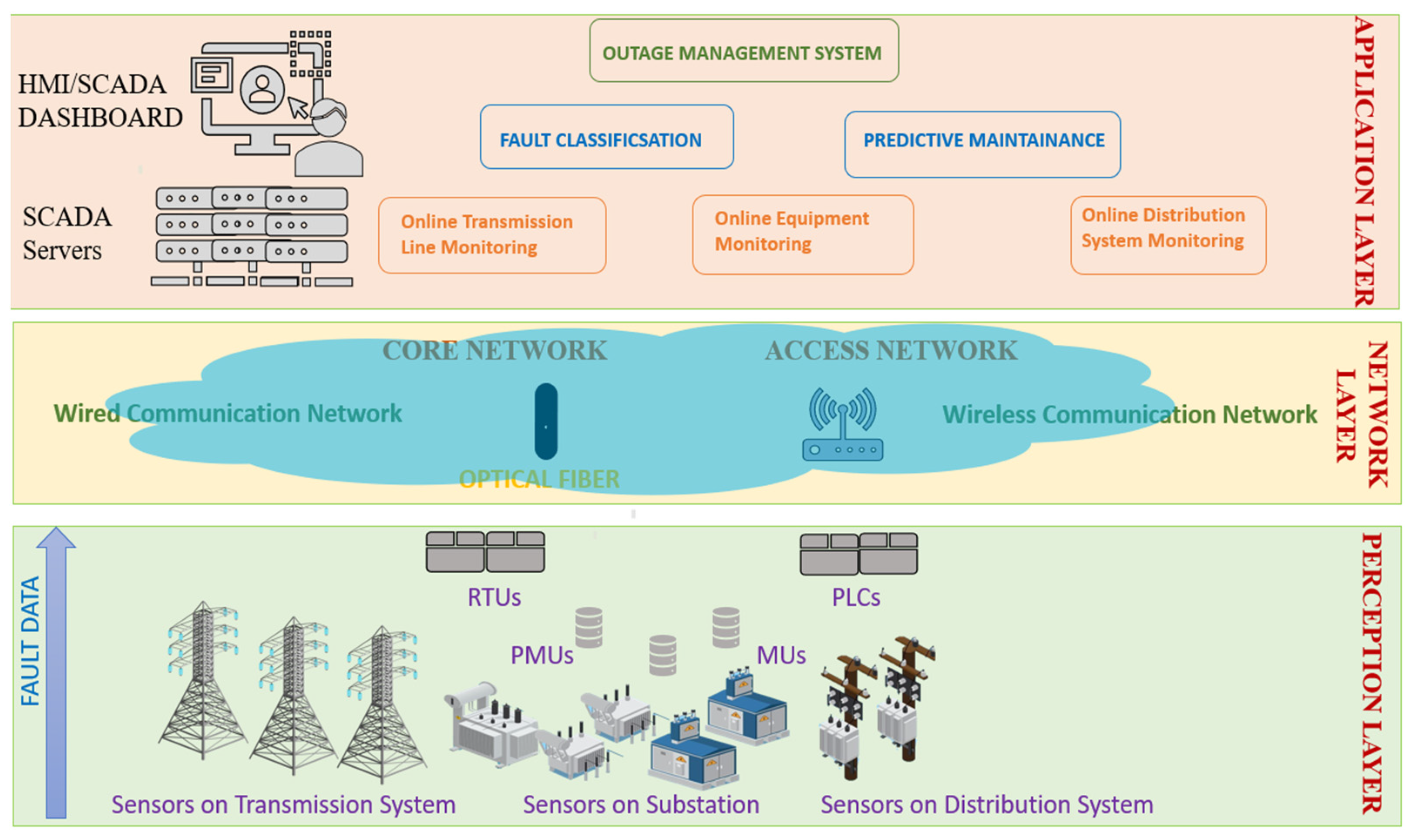
Table 3. A summary of the scope for future developments in transmission and distribution systems with its integration with modern-day sensor technology.
Power Grid
Components
Present
Characteristics
Future Development
Considerations
Transmission
System
1. Operator based controls1. Automatic controls
2. SCADA support2. Time synchronized measurements
3. Early integration of RTUs, PMUs3. ‘Adaptive’ transmission line instruments with multi-level coordination.
4. Early integration of Wireless Sensing Network4. Incorporation of economical energy management techniques and bulk storages.
5. Sensor based real-time monitoring.5. ‘Faster-than-real time’ monitoring.
6. Congestion issues6. Switchable network structures to relieve congestion issues.
7. Uni directional flow of power with early integration and islanding of microgrids7. Bidirectional flow of power with transformation to smart grids.
8. Vulnerable to threats like natural calamities, destabilizing issues, cyber security threats etc.8. Incorporation of IoT based real time condition monitoring and predictive maintenance along with cyber security protocols.
Distribution
System
1. ‘Floating’ on transmission line1. Distribution automation with advanced distribution management system.
2. Monitoring and controls restricted to substation2. On-site, non-invasive, and active distribution system asset monitoring.
3. Radial structure3. Facilitation of bidirectional power
4. Limited controllability4. Local and autonomous controls
5. Congestion issues5. Switchable network structures to relieve congestion issues.
Publisher’s Note: MDPI stays neutral with regard to jurisdictional claims in published maps and institutional affiliations.

