Article

A Composite Control Method for Permanent Magnet Synchronous Motor System with Nonlinearly Parameterized-Uncertainties

1
School of Electronic and Optical Engineering, Nanjing University of Science and Technology Zijin College, Nanjing 210023, China
2
School of Electronic and Control Science, Nanjing Tech University, Nanjing 211816, China
*
Author to whom correspondence should be addressed.
Energies 2022, 15(19), 7354; https://doi.org/10.3390/en15197354
Submission received: 24 August 2022 / Revised: 22 September 2022 / Accepted: 3 October 2022 / Published: 6 October 2022
(This article belongs to the Special Issue Control in Mechanical-Electrical Energy Conversion System)

Abstract

:
In many industrial practices, it needs a permanent magnet synchronous motor to provide enough torque, such as autonomous vehicle driving. In the operation of a permanent magnet synchronous motor, the nonlinearly parameterized-uncertainties degrade control performances, causing the instability of motor speed and output torques. Based on the analysis of temperature effects and friction torque model, a composite controller is proposed in this paper which considers model uncertainties and external disturbances. An adaptive controller involving an online time-varying scaling gain is employed to eliminate the influence of nonlinearly parameterized-uncertainties. In addition, an extended state observer (ESO) is used to estimate the disturbance in the control system in which the estimated value is used to compensate for the feed-forward. Numerical simulation and experiment are performed and the results show that the proposed method may alleviate the performance degradation due to nonlinearly parameterized-uncertainties and disturbances. Simultaneously, it may improve the stability and anti-disturbance capacities of the system.

1. Introduction

Recently, permanent magnet synchronous motors (PMSMs) is widely applied in industrial applications due to its small size, lightweight, high energy density, and high reliability, especially in the field of advanced manufacturing and autonomous vehicle driving [1,2,3]. PMSM drive system with high performance generally adopts field-oriented control, which has excellent performance for dynamic and static speed regulations. However, the nonlinearly parameterized-uncertainties in the system decrease the accuracy of the magnetic field orientation. Moreover, the conventional PI controller of the motor system with fixed gains exhibits a poor speed regulation performance with the variation of load torques [4].
Generally, there are more or less nonlinearly parameterized-uncertainties in the real industrial environment. First of all, a long-running motor with load may run in a high-temperature case, resulting magnetism loss for those permanent magnetic with high heat sensitivity. Meanwhile, the value of the stator resistance increases according to the temperature. In contrast, the value of the rotor flux linkage and the stator resistance is usually considered as constant, which may degrade the performance of PMSM. Besides, the impact of friction torques among some parts of the motor is usually ignored. However, in a real system, the increase of contact area and pressure between the shaft and other components are also capable of increasing static friction so that the startup and running performance of PMSM may be negatively affected.
Due to the unavoidable appearance of uncertainties in real systems, it is always difficult to obtain an exact model with high accuracy [5]. One practical approach is the off-line identification or modeling before implementations [6,7], while its employment condition is limited since it is only efficient for a time-invariant system. Therefore, there is few control methods overcoming the difficulties of nonlinearly parameterized-uncertainties. Variable structure control and robust control can competently deal with such uncertainties. Unfortunately, they can merely ensure that the tracking error of the system converges within a specific limit value while it cannot be realized as tracking with zero error [8,9]. A time-varying proportional gain method is presented and control law is designed according to dynamic high-gain control techniques [10,11,12,13]. However, it is inevitable to guarantee a Lipschitz continuous condition to achieve an asymptotically stable result. A finite-time stable controller with time-varying gains is proposed by Bhat and and his colleagues [14]. They adjusted parameters online by two dynamic equations. It’s worth mentioning that their method involved a complicated procedure of recursive determination of the virtual controller. As the order of the system increases, the criterion of gain selections becomes conservative due to a large number of mathematical estimations. A variable structure iterative learning controller is addressed and a learning law is adopted to realize the completed convergence of tracking errors by Xu and his colleagues [15]. In [16], an adaptive repetitive learning control (ARLC) scheme is proposed for permanent magnet synchronous motor (PMSM) servo systems with bounded nonparametric uncertainties. An extend the adaptive sliding mode control arrangement to periodic case to suppress the torque ripple by using a series-structure resonant controller is proposed in [17]. In [18], the authors proposed a proportional-type full-state observer is combined with a disturbance observer to deal with the model uncertainties. A method of learning control is studied utilizing the norm bound of uncertainties and the robustness of the controller so as to ensure the stability of the system and to effectively eliminate the tracking error [19,20,21]. Inspiring by the homogeneous system theory, a novel non-recursive adaptive controller design framework is proposed to solve the problems of a class of nonlinear systems with nonlinearly parameterized-uncertainties [22,23]. It can obtain a stabilizer including a dynamic scaling gain function and a constant gain vector. The gain vector can be easily acquired when the dynamic scaling gain is adjusted online according to the explicit self-tuning law. Compared with the existing recursive design methods, the proposed non-recursive method reduced the complexity of the controller and averted the difficult estimation of interior nonlinearly parameterized-uncertainties.
In applications, various external disturbances may unavoidably occur in the PMSM driving system, such as parameters perturbation and load torques, which may put some negative impacts on the stability and the rapidity of the motor. However, the conventional PID controller cannot have an excellent effect on rejecting disturbances although the feedback can eventually converge to the value reference in a long time. Hence, using an observer to estimate the disturbance value in the PMSM control system has great significance. Many researchers devise various control methods, such as frequency disturbance observer [24], time-domain disturbance observer, sliding mode disturbance observer, and so on. In this paper, an extended state observer is applied to estimate disturbance in the process of motor operation due to its superior characteristic of accurate evaluation both for state variables and disturbances. It is usually employed for output feedback-based disturbance rejection control.
In this paper, we firstly analyze two kinds of nonlinearly parameterized-uncertainties in a PMSM control system. Specifically, the influence on remanent magnetism and the coercivity of permanent magnet caused by the change of temperature are illustrated. Then, the influence on stator resistance is analyzed. Based on the analysis of Stribeck friction model, the influences of friction on the performance of motor systems are elaborated. Furthermore, simulation results depicted adverse effects on output torques and the stability of control system of these uncertainties. We combined an adaptive controller and an ESO to handle the adverse effects caused by the nonlinearly parameterized-uncertainties in PMSM and to improve the stability and the anti-disturbance capability.
The main contribution of this paper can be summarized as follows
  • The proposed controller uses a non-recursive design framework, the stability analysis and controller design can be separated, and has a fixed architecture framework, that is easy to design and implement for engineering;
  • The proposed controller adopts a one-step adaptive law to deal with parametric uncertainties of the PMSM system, which is an one-step designed adaptive mechanism which is more direct and effective;
  • The proposed controller applied the nonsmooth control technique which has better convergence performances around the equilibrium points and greater robustness.
Finally, experiment results show that the driving system can quickly track the reference speed in finite time and has an excellent control performance.

2. The Mathematical Model of PMSM

The voltage equation of a surface-mounted PMSM in the rotor field-oriented d q frame:
u d = R s i d + L d d i d d t p ω r λ q u q = R s i q + L q d i q d t + p ω r λ d
where u d and u q are the stator voltages of d and q axes, while i d and i q are the stator currents of d and q axes respectively. ω r is the angular velocity, and p is the number of pole pairs. R s indicates the stator resistance. λ d and λ q are the stator flux of d and q axes. T L stands for the load torque. T e is the output torque of the motor and λ f is the rotor flux linkage. L d and L q are the stator inductance of d and q axes. J is the rotor inertia, and B is the viscous friction coefficient.
The motion equation can be described as follows,
J d ω r d t = T e T L B ω r
According to the following relationship,
λ d = L d i d + λ f λ q = L q i q
T e = 3 p 2 λ f i q
the state equation of PMSM can be described by Equations (1) and (2) as:
d i d d t = R s L d i d + L q L d p ω r i q + 1 L d u d d i q d t = R s L q i q + L d L q p ω r i d + p ω r λ f L q + 1 L q u q d ω r d t = 3 P 2 J λ f i q + T L J B J ω r
In order to eliminate the coupling between i d and i q , the FOC method of setting i d * = 0 obtains an excellent control performance. The system (5) can be simplified as the form written in (6).
d i q d t = 1 L q ( R S i q p ω r λ f + u q ) d ω r d t = 1 J ( T L + 3 p λ f i q 2 B ω r )
According to (6), the FOC control system of PMSM can be described in Figure 1.

3. Analysis of Nonlinear Parameterized-Uncertainties

3.1. Nonlinear Parameterized-Uncertainties in PMSM

The nonlinear parametric uncertainty analysis is given below, including: temperature and friction.

3.1.1. Temperature Change

Magnetism Loss and Coercivity

Due to the high sensitivity of permanent magnets, the magnetism loss and coercivity change relied on the change of temperature cannot be ignored in the PMSM control system. It may lead to the fluctuation of the permanent magnet flux linkage ( λ f ), and result in the instability of the output torque. The relationship among coercivity H c , magnetism loss B r and temperature T are illustrated as below:
B r ( T ) = B r ( T 0 ) [ 1 + α 1 ( T T 0 ) ]
H c ( T ) = H c ( T 0 ) [ 1 + α 2 ( T T 0 ) ]
where T 0 is the reference temperature. α 1 and α 2 are the temperature coefficient.

The Change of Stator Resistance

The winding temperature changes as the heat generates during the running process, and the stator resistances also vary with the fluctuation of winding temperatures. According to relevant technical regulations [25], the relationship between stator resistance and temperature can be described as:
R s = R 0 234.5 + T 234.5 + T 0
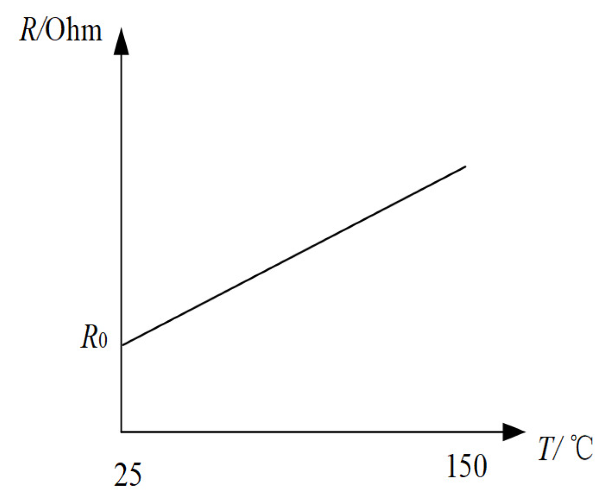
where R s is the stator resistance in current working temperature. R 0 is the resistance at room temperature (25.0 °C). The curve of stator resistance changing with the increment of the temperature can be illustrated in Figure 2. However, in a realistic system, the temperature increment has a significant relationship with the uncertainties of the external environment, leading to the nonlinear change of stator resistances.

3.1.2. Friction Torque

Friction is unavoidable and complicated phenomenon in the control system. For PMSM, friction can lead to tracking errors, limited cycles, and undesired stick-slip motion [26]. According to the dynamic equation of PMSM (5), the effect of friction is expressed by the correlation between the viscosity coefficient and the velocity. The simplicity of this form leads to the fact that the influence on the motor control system caused by friction which cannot be expressed completely. In practical engineering, the friction torque is usually a combination of Coulomb friction, viscous friction (Stribeck friction model), and Stribeck effect, in which the latter is recognized to produce a destabilizing impact at very low speed. The relationship between friction moment and speed may be described by Equation (9) as follows,
M f = s i g n ( ω r ) M c + s i g n ( ω r ) ( M m M c ) exp ( ( ω r ω s t r ) 2 ) + B ω r
where, M f is the friction torque and M c is the Coulomb friction moment. M m is the maximum static friction moment, and ω s t r is the Stribeck velocity. The maximum static friction moment is greater than the Coulomb friction torque, and the Coulomb friction force is constant in the running process of PMSM. The second term in (10) reflects the characteristics of friction torque under extremely low-speed conditions. The curve of friction torque can be illustrated as in Figure 3.
In general, ω s t r is very small, so that the Stribeck effect can be ignored as the motor runs at a high speed and (10) can be simplified as the following form (11):
M f = s i g n ( ω r ) M c + B ω r
According to (11), the friction torque can be equivalent to the combination of Coulomb and viscous friction at high speed, without any change, which has little impacts on PMSM control system. However, the Stribeck effect cannot be ignored in low running speed. According to (10), the friction torque shows a strong nonlinear characteristic, and the traditional PI control system has limited bandwidth, so that it is difficult to effectively suppress the high-frequency disturbance. Therefore, it is obvious that the influence of friction torque on the system at low speed.
Friction torque among some parts in the motor may change due to the uncertainty of some external conditions. The volume of the bearing and coupler may expand due to thermal expansion caused by a rise of indoor temperature, which leads to the increase of the contact area between the shaft and these two parts. Therefore, the static friction force may increase. Furthermore, the humid working condition may cause some parts (such as the bearing) rust, which also enhances the contact area between some parts. Meanwhile, friction torque may increase since the roughness between contacts surfaces may increase as the existence of some iron rust [27].

3.2. Simulation of Nonlinearly Parameterized-Uncertainties in PMSM

A simulation of nonlinearly Parameterized-uncertainties was performed in PMSM considering the following parameters: temperature and friction

3.2.1. Simulation of the Influence of Temperature Change

Since there is no disturbance about temperature in existing PMSM model, it is difficult to study the influence of temperature by conducting simulation. In this paper, according to the state equation of PMSM and corresponding temperature (9), a simulation model with temperature disturbance is constructed.
According to the Hudson User Manual, the specifications of motor M-2310P-LN-04K introduce that the maximum winding temperature is about 150 °C We conduct simulation for FOC system within a temperature range from 25 °C to 150 °C. According to (9), the stator resistance changes linearly with the increase of temperature. Initially, the stator resistance at indoor temperature (25 °C) is 0.36 Ω . Then, it increases to 1.06 Ω at 150 °C. In a realistic system, temperature changes have a significant relationship with the uncertainties of the external environment, bringing nonlinear changes of the stator resistance. Parameters of PMSM used in the simulation are shown in Table 1.
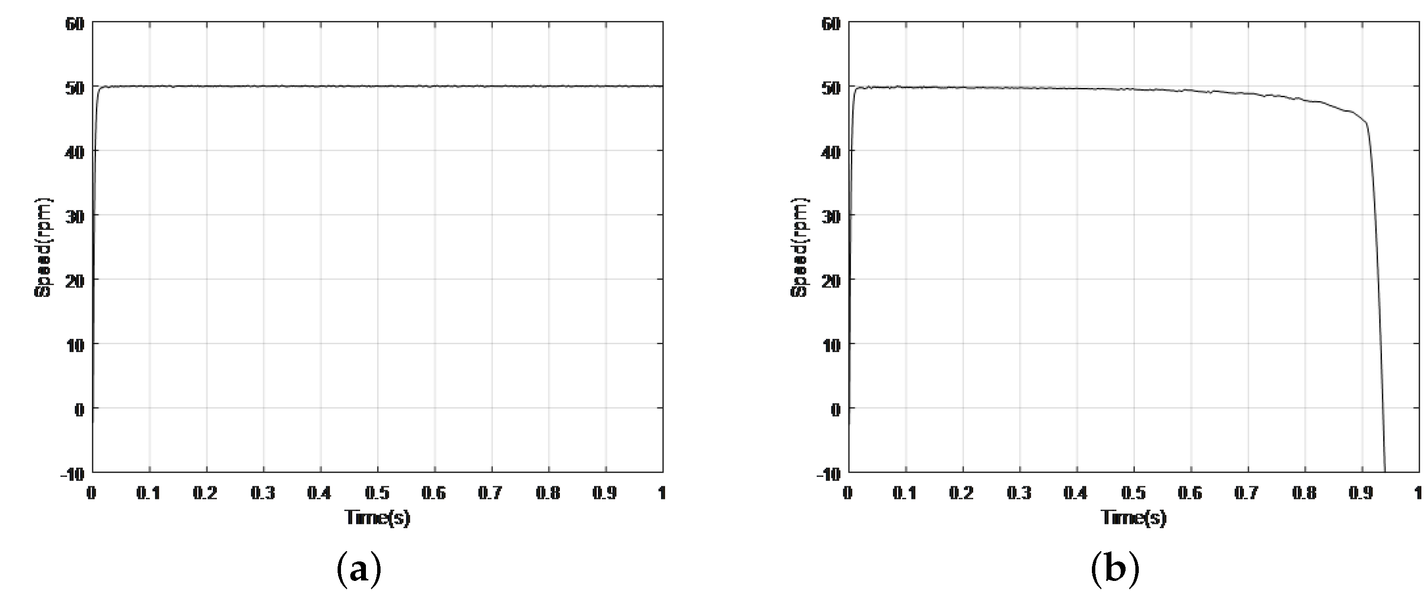
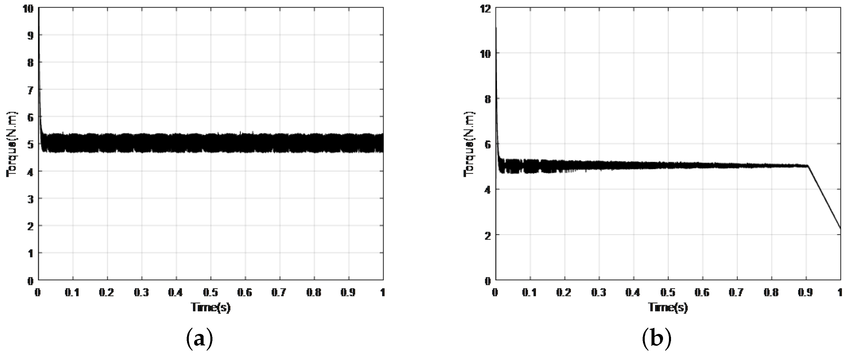
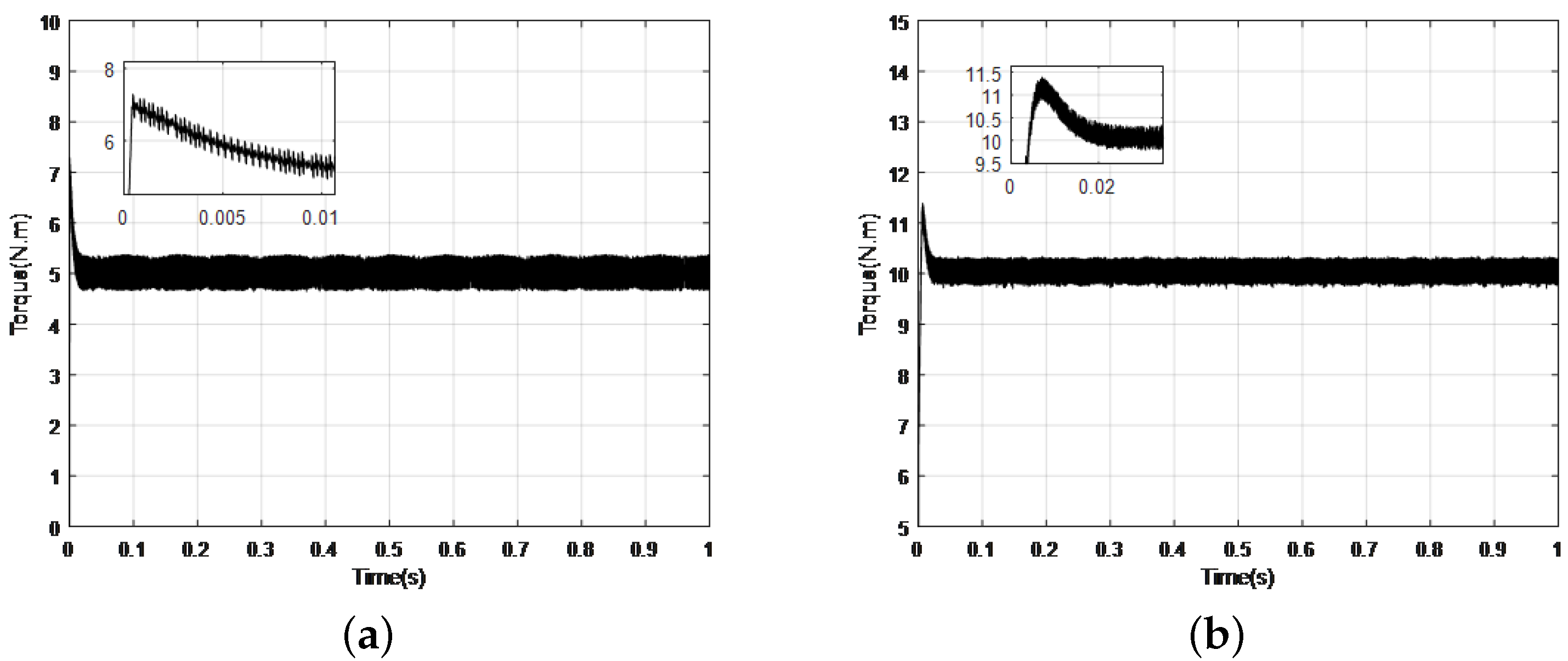
Figure 4a,b are the response curves of speed. Motor starts with load torque at T L = 5 N·m. From the results, the motor runs steadily without temperature influence in Figure 4a. However, the speed of PMSM drops rapidly with the change of stator resistances and the flux in Figure 4b, which eventually results in the unstable performance of the control system. Figure 5a,b (response curves of torque) show a similar result, similar as in Figure 2. With the increment of the temperature from 25 °C to 150 °C the amplitude of torque decreases gradually, and the torque also drops rapidly.

3.2.2. Simulation of the Influence of Friction Torque

Since the weak effect from static friction on PMSM, we set the speed reference as 30 rad per minute in simulation.
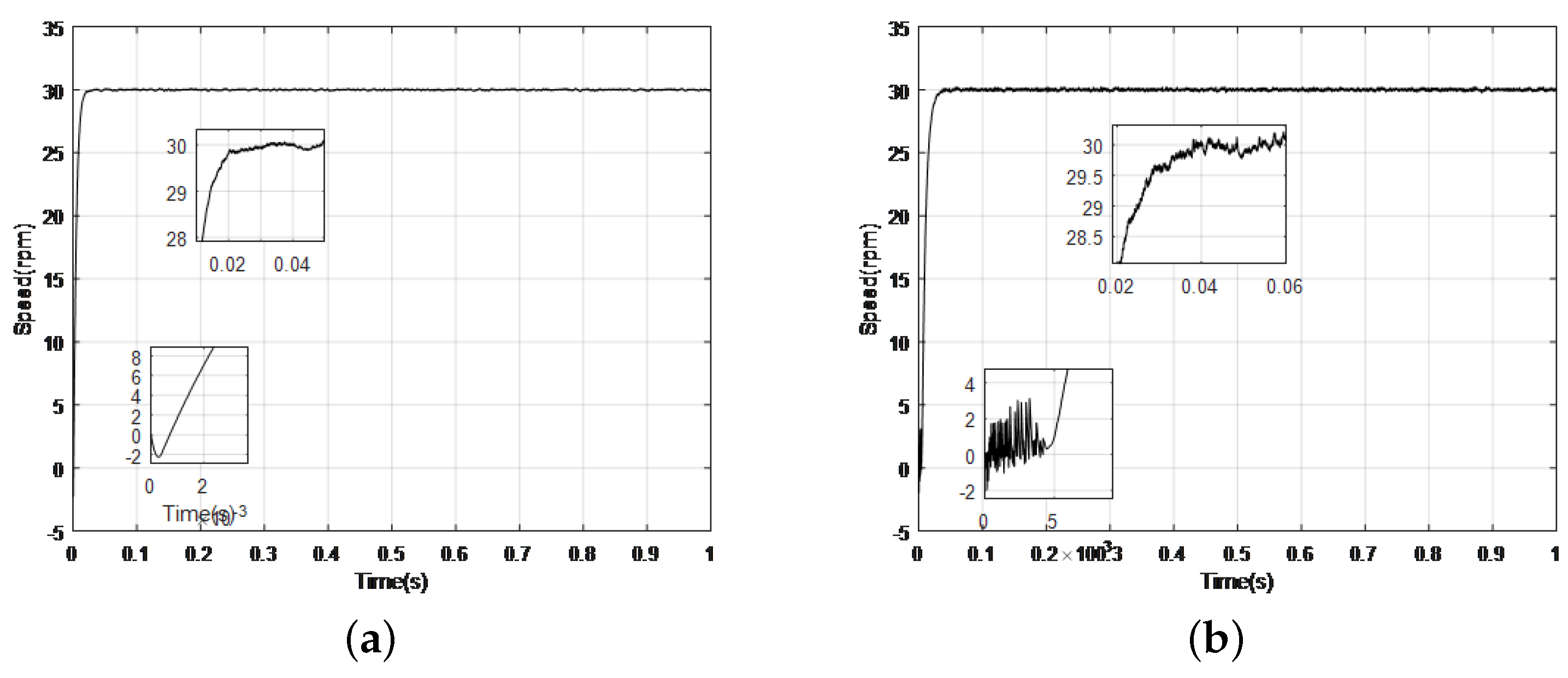
Figure 6a,b are the response curves of speed. Motor starts with a load torque at T L = 5 N·m and the friction moment is applied in PMSM. From the results, the motor with friction influence starts with vibration and run less stability. Figure 7a,b are the response curves of the torque. If the torque curve with friction influence has a smaller overshoot, the motor ignoring friction influence has a higher response speed.

3.2.3. Control Strategy

The non-recursive adaptive stabilizing controller [23] is proposed for a class of lower-triangular nonlinear systems with nonlinearly parameterized-uncertainties, which can be described by the following form
d x i d t = x i + 1 + f i ( θ , x ¯ i ) , i N 1 : n 1 d x n d t = u + f n ( θ , x )
where x ¯ i = c o l ( x 1 , x 2 , , x i ) , x = x ¯ n , and u are respectively the system partial state vector, full state vector and control input. θ r is unknown time-varying or constant parameter vector. f i ( · ) is a c1 nonlinear function satisfying a vanishing condition ( f i ( θ , 0 ) = 0 ). According to [27], the following assumption is satisfied for following relationship of f i ( θ , x ¯ i )
f i ( θ , x ¯ i ) δ i ( θ ) γ i ( x ¯ i ) j = 1 i x j r i + τ r j i N 1 : n , 0 j i
where θ is bounded and δ i ( θ ) τ . r is the homogeneous dilation weight. r i = r ( i 1 ) + τ . τ is the homogeneous degree ( τ [ 0 , 1 ) ).
The stabilizing control law is designed as:
v = K i = 1 n s i g n ( z ) z r n + τ r i u = L n + 1 v σ ^ = c 1 L ρ z Δ r 2 k L = L 1 + ρ max 0 , c 2 σ ^ c 3 L 1 ρ z = x i L i
where ρ = 1 ( 1 τ ) / r n [ 0 , 1 ) . c 1 , c 2 , c 3 are designed to be constant. L is a time-varying scaling gain, and x r = ( x i p / r i ) 1 / p   p = 2 . K = [ k 1 , k 2 , k 3 k n ] is a constant gain vector corresponding to a Hurwitz polynomial.
Though the adaptive method based system (13) with a concise structure, some external disturbances are not considered in this system. However, in practical system, load disturbances and external disturbances may generate undesirable behavior on both stability and response speed of PMSM system. Hence, the closed-loop performance is affected to a extent.

4. Composite Controller Design

Considering that the motion equation of PMSM (2) also satisfied system (12), our purpose is to design an efficient composite controller for PMSM system with nonlinearly parameterized-uncertainties so as to improve the system stability and capacity of anti-disturbances.

4.1. Adaptive Controller Design

Since the control purpose of the PMSM drive system makes the motor speed track the reference speed value, the speed tracking error is defined. The dynamic tracking error of the speed can be written as e = ω r * ω r . Then, we have following relationship
J d ω r * d t J d ω r d t = J d ω r * ω r d t = J d ω r * d t T e + T L + B ω r = J d ω r * d t T e + T L B ( ω r * ω r ) + B ω r *
Such that:
d e d t = 3 p λ f 2 J i q B J e + B J ω r * + T L J + d ω r * d t
The motion equation of PMSM can be rewritten as following form:
d e d t = 3 p λ f 2 J u B J e + f ( θ , x ) + d ( t )
where f ( θ , x ) is nonlinear function with nonlinear parameterized-uncertainties and d ( t ) is the external disturbance ( d ( t ) = B ω r * J + T L J + d ω r * d t ).
Firstly, the influence caused by f ( θ , x ) is eliminated utilizing the new adaptive controller, and the PMSM control system in the absence of d ( t ) is considered as:
d e d t = 3 p λ f 2 J u B J e + f ( θ , x )
Coordinate Transformation: Consider the transformation as the following form:
z = e L , v = u L 2
The system (15) can be rewritten as the following form:
d z d t = B L J z 3 P λ f L 2 J υ 1 L d L d t z + f ( θ , x ) L
where L is a dynamic scaling gain function, which can be online updated according to an explicit self-tuning adaptive law:
d L d t = L max { 0 , a σ ^ b L }
with L ( 0 ) 1 , where a, b are positive design parameters. Denoting that σ ^ is the estimation of σ , it may be updated by following functions:
d σ ^ d t = c L z 2 k
where c, k are design constant.
Dynamic Control Law: Aiming to design a controller such that the speed ω of the motor in the system (2) can asymptotically track the reference trajectory. A dynamic control law can be expressed in the following form [23]:
v = K sgn ( z ) z r + τ
where r = 1 , τ = 0 . K is a constant gain corresponding to a Hurwitz polynomial.
According to (13), we have
u = i q * = K L 2 sgn ( z ) z = K L 2 sgn ( e L ) e L

4.2. ESO Design

After eliminating the adverse effects of f ( θ , x ) , the dynamic equation of PMSM (8) can be equivalently represented as:
d e d t = B J e 3 P λ f 2 J u + d ( t )
Defining x 1 = e , x 2 = d ( t ) , A = B / J , B = ( 3 P λ f ) / 2 J , the system (15) can be depicted as:
x ˙ 1 = A x 1 + B u x ˙ 2 = d d ( t ) d t
To obtain the extended states of PMSM control system, a linear ESO can be designed as [27]
d z 1 d t = z 2 β 1 ( z 1 x 1 ) + b u d z 2 d t = β 2 ( z 1 x 1 )
where z 1 , z 2 are the estimates of x 1 , x 2 and β 1 , β 2 are the observer parameters which are need to be designed.
In order to satisfy the control objective of dealing with the adverse effects caused by nonlinearly parameterized-uncertainties and effectively suppressing various disturbances in the PMSM system, combine Formulas (23) and (26), a kind of composite controller (non-recursive adaptive controller + ESO) has been introduced as the following form:
u = k L 2 sgn ( e L ) e L + 2 J 3 P λ f z 2
The whole control block diagram of composite controller can be found in Figure 8.

5. Experiment Results

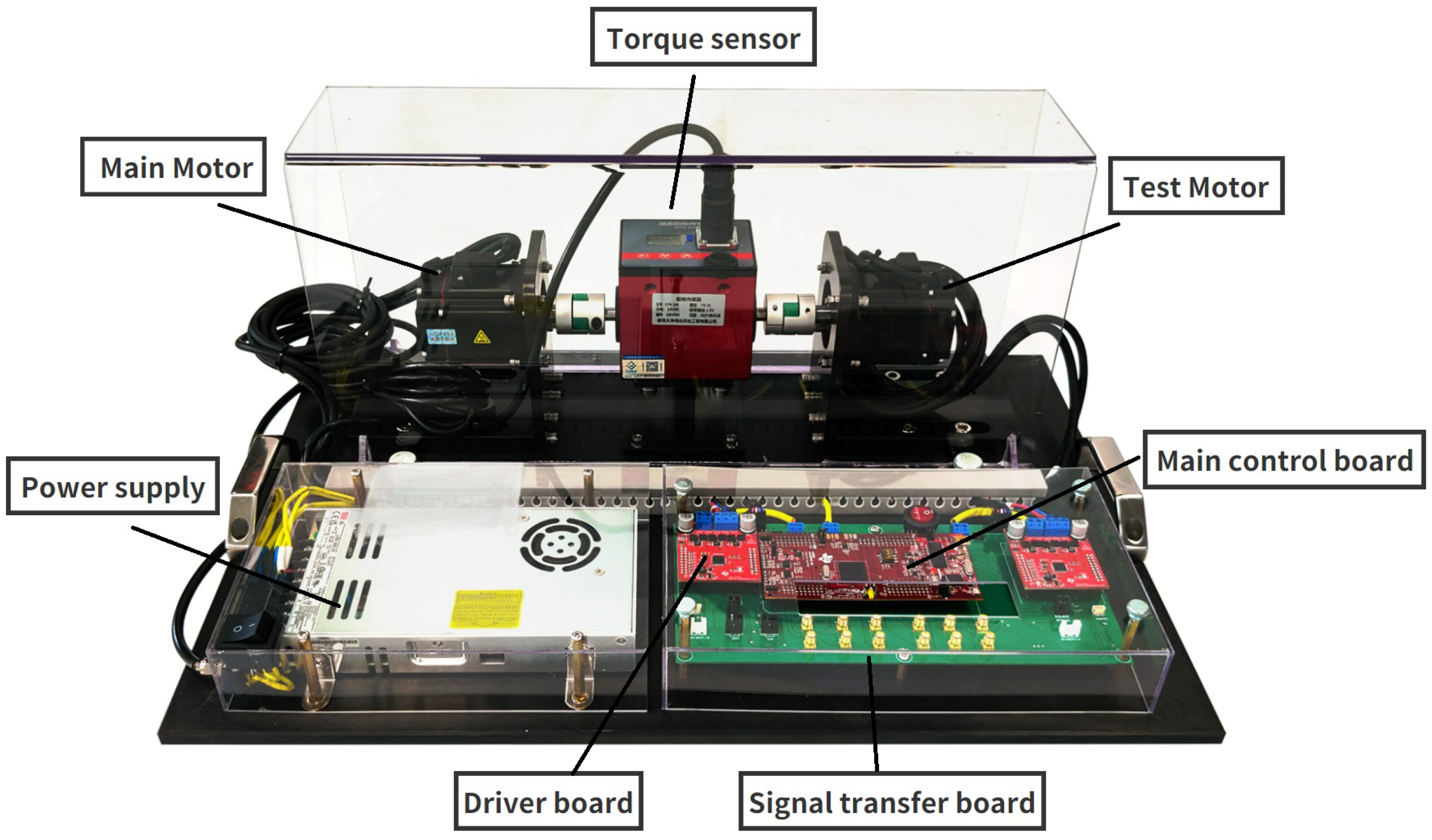
According to existed methods, a model in MATLAB is built to conduct experiments, and the integral control method is implemented by the TI-TMS320F28379D control board on a 426 w PMSM. The specification of PMSM is the same as the parameters in Table 1. Figure 9 shows the experimental platform setup. Considering the complexity of experiments, we take the uncertainty of friction torque as an example to illustrate its impacts by increasing artificial friction (increasing the contact area). The control parameters for the experiments are shown in Table 2. Concerning that the influence of the friction force may be more remarkable at low speed, we set the reference speed as 100 rad per minute in experiments and the load torque is chosen as T L = 5 N·m is applied to PMSM when it starts.
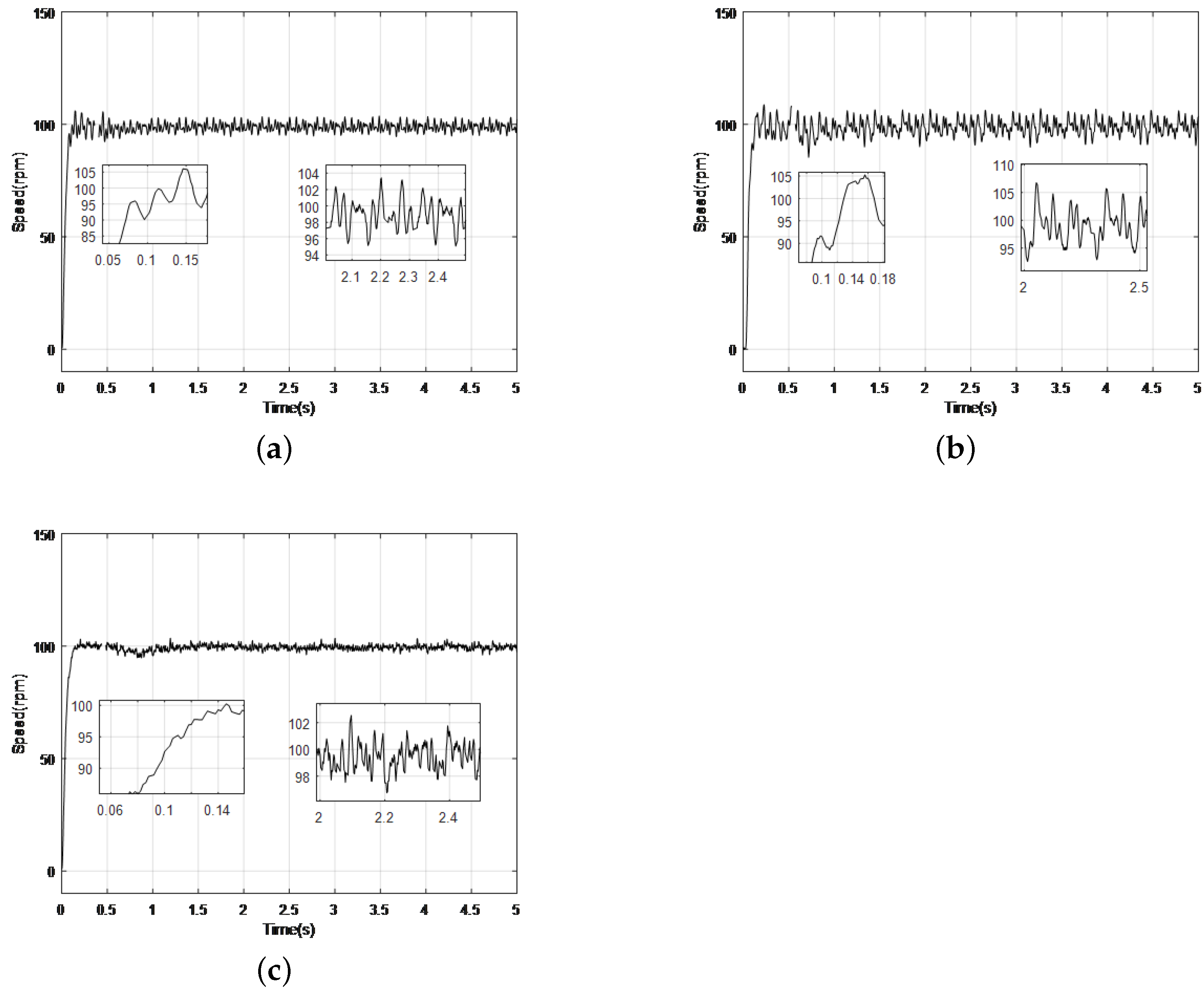
In the case of tracking a step signal, the response curves of speed in Figure 10a,b, the PID controller with artificial friction influence runs with higher amplitude (107 rpm) than the controller without friction influence (104 rpm). In Figure 10c, the composite controller with friction influence has less settling time (0.15 s) than the PID controller (0.17 s) with friction influence in Figure 10b. Besides, the speed trajectory of the PID controller in Figure 10b is less stable than that of the composite controller showing smaller overshoot (1%) than speed curves in (a) (6%) and (b) (5%). The maximum tracking error of the step response is 12.5 rpm.
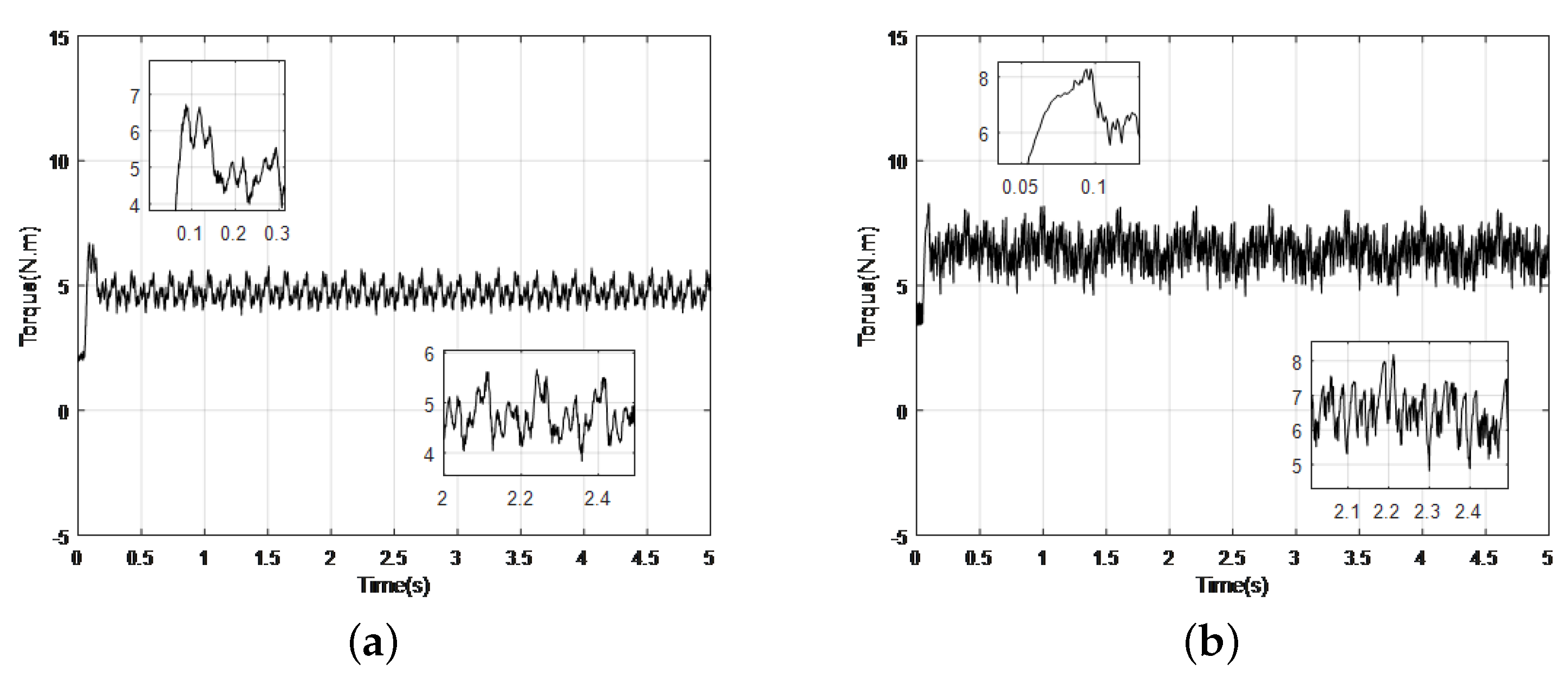
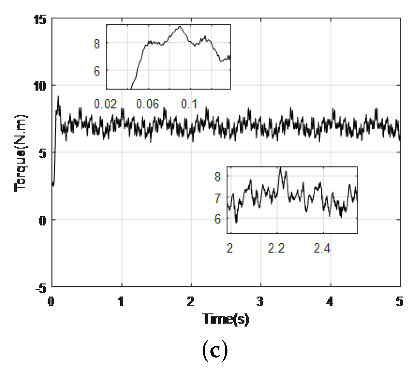
According to the response curves of torque in Figure 11a,b, the PID controller with artificial friction influence runs with a more violent vibration (4.8 N·m 8.2 N·m) than the controller without friction influence (3.8 N·m 5.6 N·m). In Figure 11c, the composite controller with friction influence has less violent vibration (5.8 N·m 8.3 N·m) than that of the PID controller in (b) showing less stability.
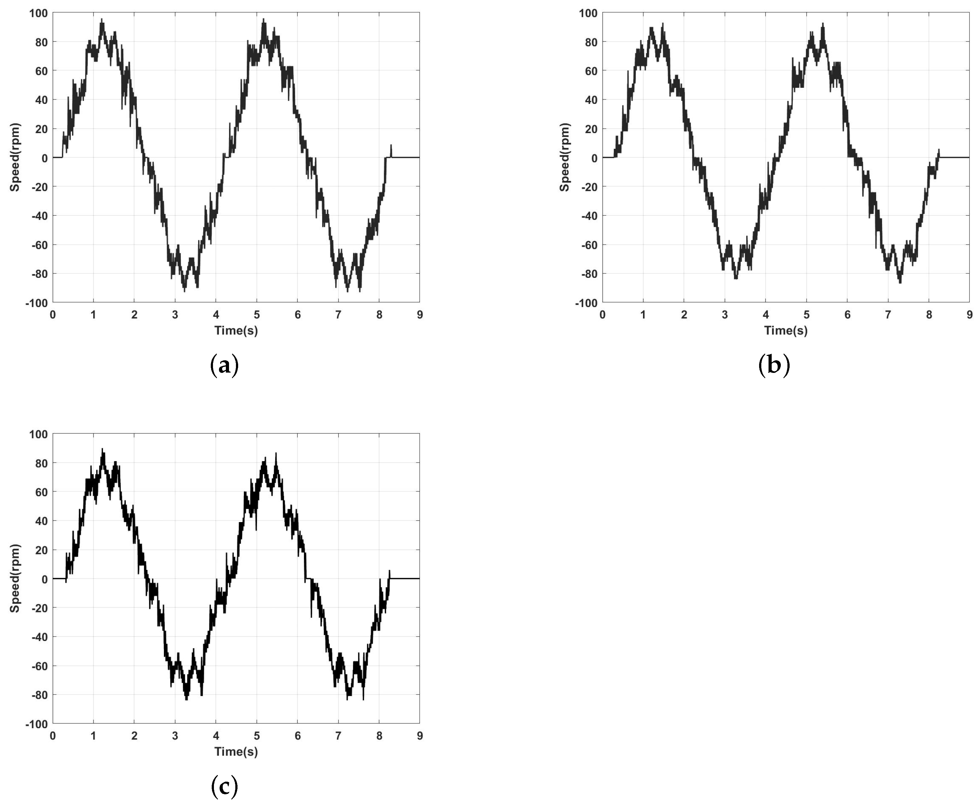
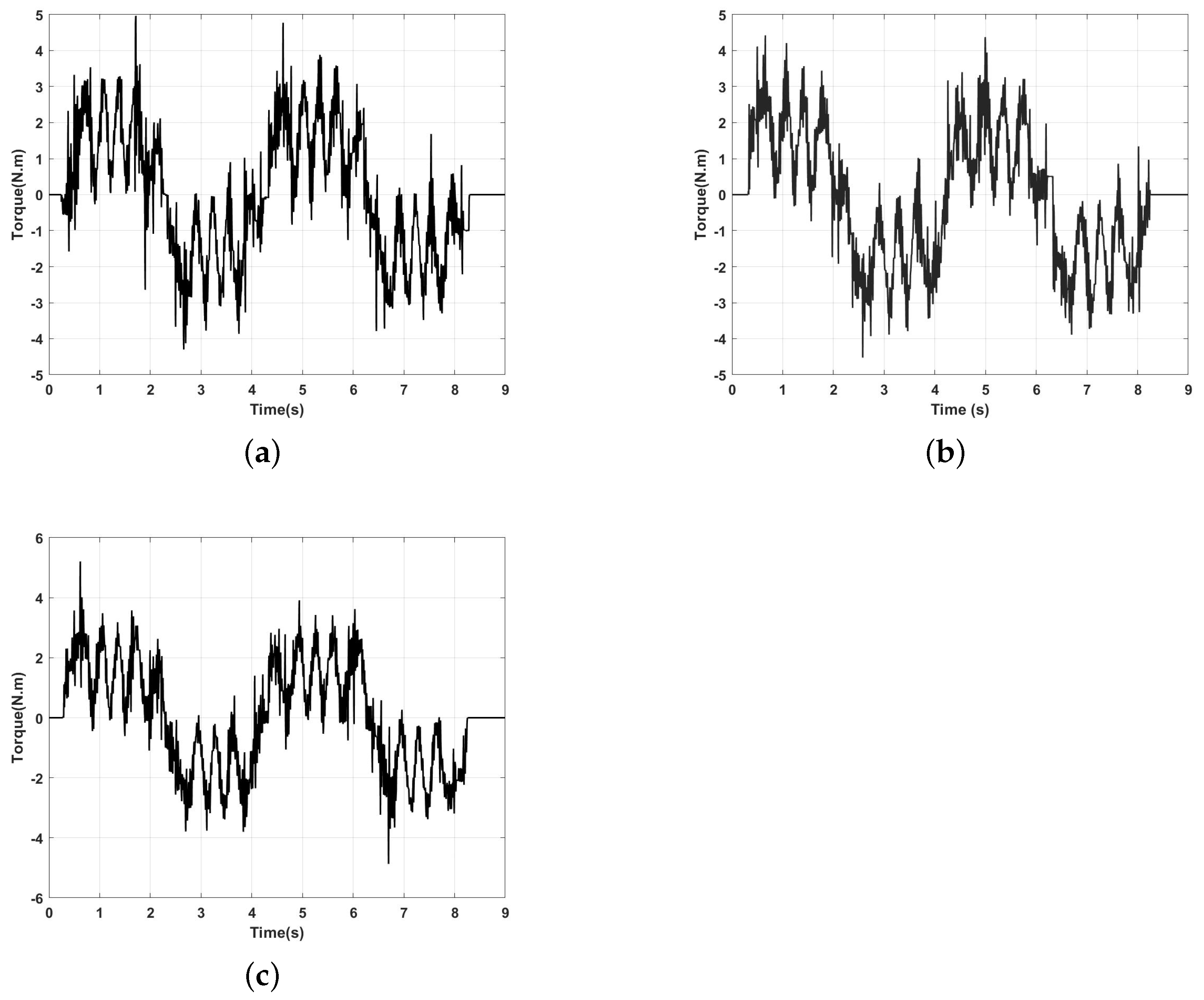
In the case of tracking sinusoidal signals (Reference track 80 s i n ( θ ) ), the response curves of speed in Figure 12a,b, and response curves of torque in Figure 13a,b, the the PID controller with artificial friction influence runs with higher amplitude (97 rpm) than the controller without friction influence (94 rpm). The composite controller with friction influence in Figure 12c has higher tracking accuracy than PID control. Maximum steady state error for sinusoidal tracking is 8.2 rpm

6. Conclusions

In this paper, some specific nonlinearly parameterized-uncertainties caused by temperature change and friction torque in PMSM have been illustrated, and some simulation results reveal the adverse influence of them. Therefore, a novel composite control method, including an adaptive controller and an extended state observer (ESO), has been applied to the FOC of PMSM to overcome the influence caused by nonlinearly parameterized-uncertainties. This composite controller has a good effect on eliminating these impacts and effectively improves the stability of the motor drive system. Additionally, through the comparison between the proposed method and the conventional PID controller, experimental results show that the control system owns a better control performance as PMSM starts with load torque.

Author Contributions

S.L.: Conceptualization, Methodology, Software, Formal analysis, Writing—original draft, Writing—review & editing. Y.S.: Conceptualization, Methodology, Validation, Writing—review & editing, Project administration, Funding acquisition. Z.S.: Software, Investigation. S.L.: Validation, Supervision, Project administration, Funding acquisition. All authors have read and agreed to the published version of the manuscript.

Funding

This research was funded by Natural Science Foundation of the Jiangsu Higher Education Institutions of China, grant number 19KJB510033.

Data Availability Statement

Data sharing is not applicable to this article as no datasets were generated or analyzed during the current study.

Conflicts of Interest

The authors declare that they have no conflict of interest.

References

  1. Ni, R.; Xu, D.; Wang, G.; Gui, X.; Zhang, G.; Zhan, H.; Li, C. Efficiency enhancement of general AC drive system by remanufacturing induction motor with interior permanent-magnet rotor. Trans. Ind. Electron. 2015, 63, 808–820. [Google Scholar] [CrossRef]
  2. Ni, R.; Xu, D.; Wang, G.; Ding, L.; Zhang, G.; Qu, L. Maximum efficiency per ampere control of permanent-magnet synchronous machines. Trans. Ind. Electron. 2014, 62, 2135–2143. [Google Scholar] [CrossRef]
  3. Zhang, G.; Wang, G.; Xu, D.; Zhao, N. ADALINE-network-based PLL for position sensorless interior permanent magnet synchronous motor drives. Trans. Power Electron. 2015, 31, 1450–1460. [Google Scholar] [CrossRef]
  4. Zhang, X.H.; Tang, Q.T. Adaptive backstepping control of interior permanent magnet synchronous motors considering parameter and load uncertainties. Control Decis. 2016, 31, 1509–1512. [Google Scholar]
  5. Yang, J.; Su, J.; Li, S.; Yu, X. High-order mismatched disturbance compensation for motion control systems via a continuous dynamic sliding-mode approach. Trans. Ind. Informatics 2013, 10, 604–614. [Google Scholar] [CrossRef] [Green Version]
  6. Zhu, Y. Multivariable process identification for MPC: The asymptotic method and its applications. J. Process Control 1998, 8, 101–115. [Google Scholar] [CrossRef] [Green Version]
  7. Zhou, Z.; Zhang, B.; Mao, D. Robust sliding mode control of PMSM based on rapid nonlinear tracking differentiator and disturbance observer. Sensors 2018, 18, 1031. [Google Scholar] [CrossRef] [Green Version]
  8. Gutman, S. Uncertain dynamical systems—A Lyapunov min-max approach. IEEE Trans. Autom. Control 1979, 24, 437–443. [Google Scholar] [CrossRef]
  9. Corless, M.; Leitmann, G. Continuous state feedback guaranteeing uniform ultimate boundedness for uncertain dynamic systems. IEEE Trans. Autom. Control 1981, 26, 1139–1144. [Google Scholar] [CrossRef] [Green Version]
  10. Praly, L.; Jiang, Z.P. Linear output feedback with dynamic high gain for nonlinear systems. Syst. Control Lett. 2004, 53, 107–116. [Google Scholar] [CrossRef]
  11. Koo, M.S.; Choi, H.L.; Lim, J.T. Universal control of nonlinear systems with unknown nonlinearity and growth rate by adaptive output feedback. Automatica 2011, 47, 2211–2217. [Google Scholar] [CrossRef]
  12. Krishnamurthy, P.; Khorrami, F. Dynamic high-gain scaling: State and output feedback with application to systems with ISS appended dynamics driven by all states. Trans. Autom. Control 2011, 49, 2219–2239. [Google Scholar] [CrossRef]
  13. Lei, H.; Lin, W. Universal adaptive control of nonlinear systems with unknown growth rate by output feedback. Automatica 2006, 42, 1783–1789. [Google Scholar] [CrossRef]
  14. Bhat, S.P.; Bernstein, D.S. Continuous finite-time stabilization of the translational and rotational double integrators. Trans. Autom. Control 2006, 43, 678–682. [Google Scholar] [CrossRef] [Green Version]
  15. Xu, J.X.; Qu, Z. Robust iterative learning control for a class of nonlinear systems. Automatica 2006, 43, 983–988. [Google Scholar] [CrossRef]
  16. Chen, Q.; Yu, X.; Sun, M.; Wu, C.; Fu, Z. Adaptive repetitive learning control of PMSM servo systems with bounded nonparametric uncertainties: Theory and experiments. IEEE Trans. Ind. Electron. 2020, 68, 8626–8635. [Google Scholar] [CrossRef]
  17. Huang, M.; Deng, Y.; Li, H.; Shao, M.; Liu, J. Integrated Uncertainty/Disturbance Suppression Based on Improved Adaptive Sliding Mode Controller for PMSM Drives. Energies, 2021; 14, 6538. [Google Scholar]
  18. Choi, K.; Kim, Y.; Kim, S.K.; Kim, K.S. Current and position sensor fault diagnosis algorithm for PMSM drives based on robust state observer. IEEE Trans. Ind. Electron. 2020, 68, 5227–5236. [Google Scholar] [CrossRef]
  19. Ullah, K.; Guzinski, J.; Mirza, A.F. Critical review on robust speed control techniques for permanent magnet synchronous motor (PMSM) speed regulation. Energies 2022, 15, 1235. [Google Scholar] [CrossRef]
  20. Deng, Y.; Wang, J.; Li, H.; Liu, J.; Tian, D. Adaptive sliding mode current control with sliding mode disturbance observer for PMSM drives. ISA Trans. 2019, 88, 113–126. [Google Scholar] [CrossRef]
  21. Xu, J.; Xu, J.X. Memory based nonlinear internal model: What can a control system learn. In Proceedings of the 4th Asia Control Conference, Singapore, 25–27 September 2002; pp. 446–451. [Google Scholar]
  22. Tan, Y.; Xu, J.X. Learning based nonlinear internal model control. In Proceedings of the IEEE 2003 American Control Conference, Denver, CO, USA, 4–6 June 2003. [Google Scholar]
  23. Zhang, C.; Wen, C. A non-recursive C1 adaptive stabilization methodology for nonlinearly parameterized uncertain nonlinear systems. J. Frankin Inst. 2018, 355, 5099–5113. [Google Scholar] [CrossRef]
  24. Ohishi, K.; Nakao, M.; Ohnishi, K.; Miyachi, K. Microprocessor-controlled DC motor for load-insensitive position servo system. IEEE Trans. Ind. Electron. 1987, 34, 44–49. [Google Scholar] [CrossRef]
  25. Che, J.; Qian, X. Analysis of temperature effect in direct torque control system for permanent magnet synchronous motor. Mach. Tool Hydraul. 2013, 41, 54–57. [Google Scholar]
  26. De Wit, C.C.; Olsson, H.; Astrom, K.J.; Lischinsky, P. A new model for control of systems with friction. IEEE Trans. Autom. Control 1995, 40, 419–425. [Google Scholar] [CrossRef] [Green Version]
  27. Ran, M.; Li, J.; Xie, L. A new extended state observer for uncertain nonlinear systems. Automatica 1995, 131, 109772. [Google Scholar] [CrossRef]
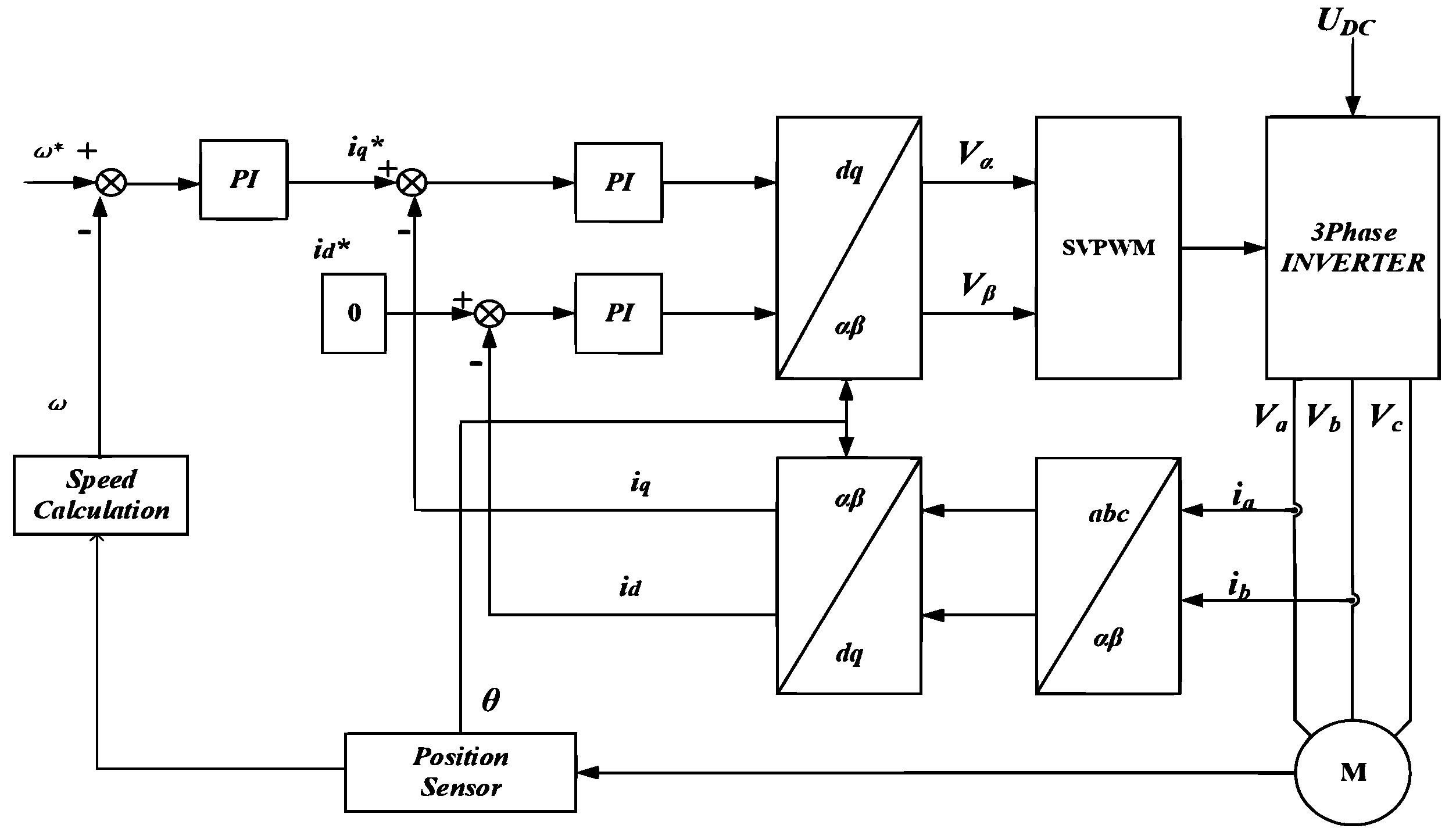
Figure 1. The principal block diagram of PMSM system based on Field Oriented Control.
Energies 15 07354 g001
Figure 2. The curve of stator resistance changing with the temperature.
Energies 15 07354 g002
Figure 3. Friction model.
Energies 15 07354 g003
Figure 4. Comparison of speed curves. (a) Without temperature change, (b) With temperature change (simulation).
Energies 15 07354 g004
Figure 5. Comparison of torque curves. (a) Without temperature change, (b) With temperature change (simulation).
Energies 15 07354 g005
Figure 6. Comparison of speed curves (a) Without friction influence, (b) With friction influence (simulation).
Energies 15 07354 g006
Figure 7. Comparison of torque curves. (a) Without friction influence, (b) With friction influence (simulation).
Energies 15 07354 g007
Figure 8. The block diagram of the composite controller.
Energies 15 07354 g008
Figure 9. The experimental platform setup.
Energies 15 07354 g009
Figure 10. Comparison of Velocity Waveforms with Step Signal Tracking. (a) Without friction torque (PID), (b) With friction torque (PID), (c) With friction torque (Composite controller) (experiments).
Energies 15 07354 g010
Figure 11. Comparison of torque Waveforms with Step Signal Tracking. (a) Without friction torque (PID), (b) With friction torque (PID), (c) With friction torque (Composite controller) (experiments).
Energies 15 07354 g011aEnergies 15 07354 g011b
Figure 12. Comparison of Velocity Waveforms with Sine Signal Tracking. (a) Without friction torque (PID), (b) With friction torque (PID), (c) With friction torque (Composite controller) (experiments).
Energies 15 07354 g012
Figure 13. Comparison of torque Waveforms with Sine Signal Tracking. (a) Without friction torque (PID), (b) With friction torque(PID), (c) With friction torque (Composite controller) (experiments).
Energies 15 07354 g013
Table 1. Specification of the PMSM.
rated power426 Wpole pairs4
rated voltage60 Vstator resistance0.36 Ohms
rated torque1.5 N·mstator inductance0.4 mH
rated current7.1 Arotor inertia3.75 kg·m 2
rated speed6000 rpmback-EMF4.64 v/krpm
Table 2. Control parameters of experiments.
Traditional PID Composite Controller
speed loop proportional gain25design parameter a0.5
speed loop integral gain0.001design parameter b0.8
speed loop differential gain0.01design parameter c1
current loop I d / I q proportional gain0.04design parameter k I d / I q 1.5
current loop I d / I q integral gain0.02constant gain K−0.5
gain of ESO23
gain of ESO4.5
current loop I d / I q proportional gain0.04
current loop I d / I q integral gain0.02
Publisher’s Note: MDPI stays neutral with regard to jurisdictional claims in published maps and institutional affiliations.