Article

Thermodynamic Analysis and Optimization Design of a Molten Salt–Supercritical CO2 Heat Exchanger

MOE Key Laboratory of Enhanced Heat Transfer and Energy Conservation, Beijing Key Laboratory of Heat Transfer and Energy Conversion, Beijing University of Technology, Beijing 100124, China
*
Author to whom correspondence should be addressed.
Energies 2022, 15(19), 7398; https://doi.org/10.3390/en15197398
Submission received: 6 September 2022 / Revised: 24 September 2022 / Accepted: 29 September 2022 / Published: 9 October 2022

Abstract

:
The performance of a heat exchanger is directly related to the energy conversion efficiency of the thermal storage system, and its optimal design is an important method to improve the performance of the heat exchanger. This paper uses the distributed parameter method to analyze the effect of the structural parameters and operating parameters of a heat exchanger on the entransy dissipation rate, the entransy dissipation number, the entransy dissipation heat resistance, entropy production rate, and entropy production number in a molten salt–supercritical CO2 concentric tube heat exchanger. The results show that the entransy dissipation rate and entropy production rate have the same trend, with the structural parameters and operating parameters, as well as the changes in the entransy dissipation number and entransy dissipation thermal resistance, jointly affected by the entransy dissipation rate and the heat exchange. Based on the above indicators, single-objective and multi-objective optimization calculations were carried out. The results show that taking the minimum entropy dissipation number, entransy dissipation heat resistance, and improved entropy production number as the objective functions, and using the heat transfer effectiveness as the evaluation index, the optimization effect is better. The ε value is increased by 41.2%, 39.5%, and 40.3% compared with the reference individual. In the multi-objective optimization, taking the minimum number of entransy dissipation and entropy production as the objective function, and using the efficiency of heat transfer and the pressure drop of the working fluid as the evaluation indicators, the optimization effect is better. Compared with the reference individual, the ε value increased by 23.5%, and Δ P h and Δ P c decreased by 51.9% and 32.5%, respectively. This study provides a reference for the optimization of supercritical CO2 heat exchangers by utilizing parameters such as entransy and entropy, which reflect the irreversible loss of the heat transfer process.

1. Introduction

Molten salt is one of the most promising heat transfer and energy storage medium, and the heat exchange between molten salt and supercritical CO2(sCO2) is of great significance for thermal storage system in solar thermal power generation [1,2]. Heat exchanger can realize the energy exchange between the hot and cold fluids, occupying a crucial position in the field of energy utilization, especially in the current background of energy conservation and emission reduction. So, it is particularly important to improve the efficiency of heat exchangers; subsequently, many studies were carried out to meet this demand [1,3]. On the one hand, new technologies, new theories, and new materials are applied to develop new heat exchangers, but there are disadvantages, such as the high cost and long cycle [3,4,5]. On the other hand, optimization design is carried out on the basis of existing heat exchanger to improve the efficiency of the heat exchanger, with the advantages of a short research period, low cost, quick effect, and so on [6,7].
The actual heat transfer process will lead to continuous attenuation of energy quality, namely, irreversible loss. Therefore, some scholars put forward the optimization rule of heat exchangers based on the second law of thermodynamics [6,7,8]. Bejan [7] et al. defined the dimensionless entropy production of heat exchangers and found that when the efficiency of a balanced-flow countercurrent heat exchanger is at 0.5, it will reach the maximum value, resulting in the entropy production paradox. To solve this problem, Hesselgreaves [8] and Ogiso [9] et al. proposed the improved form of entropy production to eliminate the paradox of entropy production. Shah [10] et al. analyzed the relationship between the efficiency of 18 different types of heat exchangers and the entropy production rate, and the results showed that when the entropy production rate was the lowest, the efficiency of the heat exchangers could be any value. In order to solve the problem of the entropy production paradox, Guo [11] et al. proposed the optimization criterion of a heat exchanger, the extremum principle of entransy dissipation, and the principle of minimum thermal resistance, based on the second law of thermodynamics. Guo [12] et al. proposed the entransy dissipation number and applied it to the evaluation of heat exchangers. Lerou [13] et al. analyzed the main causes of entropy generation of a heat exchanger in the cooling process, obtained a mathematical model for quantitative calculation of entropy generation, and carried out a structural optimization design by using the principle of minimum entropy generation. Chen [14] et al. proposed an entransy dissipation-based thermal-resistance method for an optimization design of heat exchangers, which could be more convenient for analysis and optimization. Wang [15] et al. optimized the wound tube heat exchanger based on the principle of minimum entransy dissipation thermal resistance. Guo [16] et al. optimized shell and tube heat exchangers with the entransy dissipation number and pressure entransy dissipation number as the objective function. Qian [17] et al. found that thermal resistance based on minimum entropy production does not always correspond to the highest heat transfer rate. Cheng [18] et al. analyzed the changes in entransy dissipation rate and entropy production rate with the change in heat exchanger working conditions, and found that the minimum entropy production rate and entransy dissipation rate does not always correspond to the best performance of the heat exchanger. Liu [19] et al. studied the applicability of the principle of minimum entropy production and the maximum principle of entransy in heat exchanger optimization. Guo [20] et al. established the principle of uniform distribution of entransy dissipation, and theoretically analyzed the application range of the principle of minimum entropy generation and the principle of extreme value of entransy dissipation. Xie [21] et al. carried out topology optimization on the needle-fin heat exchanger structure based on the principle of minimum entropy production, and the result showed that the heat storage of the system could be increased by 10.2%. Guo [22] et al. defined the dissipative thermal resistance of the heat exchanger based on the entransy dissipative thermal resistance and found that it has universality. Li [23] et al. optimized the design of serrated fins in plate-fin heat exchangers using the principle of minimum entransy dissipation heat resistance. Han [24] et al. optimized the structure of the new airfoil heat exchanger based on the idea of synergistic strengthening based on the distribution matching of entransy, and proposed two non-uniform fin distribution structures. Based on the exergy analysis of the coiled-tube heat exchanger, Han [25] et al. proposed the heat transfer exergy loss number, and used this dimensionless parameter to optimize the design of the coiled-tube heat exchanger. Although entropy theory and entransy theory have been used to study the optimization of heat exchangers, the influence of structural parameters and operating parameters on heat exchangers is rarely reported.
In this paper, the concentric tube heat exchanger is taken as the research object, molten salt and supercritical CO2 are selected as the heat transfer medium, and the mathematical model is established by the distributed parameter method. The variation in the entransy dissipation rate, the entransy dissipation number, the entransy dissipation resistance, the entropy production rate, and the improved entropy production rate, with the structural parameters and operational parameters of a heat exchanger with a constant heat exchange surface and constant heat exchange, are analyzed. Based on the above parameters and heat transfer coefficient, single-objective optimization and multi-objective optimization calculations are carried out. Through this paper, by thermodynamic and optimization analysis of a supercritical CO2 heat exchanger, on the one hand, we can reveal a change in the law of irreversible loss of the heat exchanger during operation and provide a certain reference for the design of a heat exchanger; on the other hand, we can provide guidance for the optimization of heat exchangers according to the optimization results.

2. The Computational Model and Model Validation

2.1. Physical Model and Heat Transfer Fluid

Figure 1 is the schematic diagram of concentric tube heat exchanger, and the inner diameter, outer diameter, and length are marked. The fluid in the tube is molten salt, and the fluid in the outer casing is supercritical CO2. The inner diameter of the heat exchanger is 0.02 m, the outer diameter is 0.034 m, and the length is 2 m.
Figure 2 shows the thermal property parameters of molten salt and sCO2, and ρ, cp, λ, and μ represent density, specific heat capacity, thermal conductivity, and dynamic viscosity, respectively. The molten salt is self-configured mixed molten salt, and its thermophysical parameters are obtained through experimental test. For the sCO2, its thermophysical parameters are obtained from NIST REPROP 9.0 [26] under the pressure condition of 8 MPa, with temperature range of 273–773 K.

2.2. The Computational Model

The concentric tube heat exchanger is divided into several units along the length, and the fluid was calculated as the steady state of one-dimensional flow, and the axial heat conduction of the inner wall was ignored, while the outer wall was adiabatic.
Continuity equation:
( ρ u ) x = 0
where u is the velocity of the fluid, in m/s.
Momentum conservation equation:
( ρ u 2 ) x + P x + f u 2 2 D ρ = 0
where P is pressure, in Pa; and f is the resistance coefficient, which is calculated by Equation (3) [27]:
f = ( 1.82 log 10 ( R e ) 1.64 ) 2
Energy conservation equation of the fluid in the tube:
A h ρ h c p , h u h T h x = α h ( T h T w ) π D
where A is the cross-sectional area, in m2; α is the heat transfer coefficient, in W∙m−2∙K−1; and D is the equivalent diameter, in m.
Energy conservation equation of outer pipe fluid:
A c ρ c c p , c u c T c x = α c ( T w T c ) π D
Energy equation of the wall:
α h ( T h T w ) = α c ( T w T c )
The convective heat transfer of molten salt is calculated by the Gnielinski correlation [24]:
N u = ( f / 8 ) ( R e 1000 ) P r 1 + 12.7 f / 8 ( P r 2 3 1 )
where Nu is The Nusselt number and Pr is the Prandtl number.
The heat transfer coefficient of sCO2 is calculated by using the local empirical correlation proposed by Jackson et al. [28]:
N u = 0.0183 R e 0.82 P r ave 0.5 ( ρ w ρ ) 0.3
P r ave = P r c p , ave c p
c p , ave = h h ave T T w
where h is specific enthalpy, in J∙kg−1.

2.3. Model Validation

The model was divided into several elements and the element independence verification was carried out as show in Table 1. The results showed that when the number of units was 100, the outlet temperature of the fluid basically remained unchanged. Therefore, 100 units were selected for subsequent calculation in order to save time and cost.
In this paper, the simulation results are compared with previous experimental results [29]. The results are shown in Table 2, and the difference between the simulation values and the experimental values is less than 4%; thus, the model can be considered reliable.

3. Result and Discussion

3.1. Thermodynamic Analysis under Constant Heat Transfer Area

The definitions of the entransy dissipation rate ( ϕ g ), entransy dissipation number ( N ED ), entransy dissipation thermal resistance ( R g ), entropy production rate ( S g ), and improve entropy production number ( N RS ) are as follows:
ϕ g = ( 1 2 C h T h , in 2 + 1 2 C c T c , in 2 ) ( 1 2 C h T h , out 2 + 1 2 C c T c , out 2 )
where C is thermal capacity, in J/K.
N ED = ( 1 2 C h T h , in 2 + 1 2 C c T c , in 2 ) ( 1 2 C h T h , out 2 + 1 2 C c T c , out 2 ) Q ( T h , in T c , in )
where the heat flow Q is calculated as
Q = m c p Δ T
R g = [ ( 1 2 C h T h , in 2 + 1 2 C c T c , in 2 ) ( 1 2 C h T h , out 2 + 1 2 C c T c , out 2 ) ] / Q 2
S g = C h ln T h , out T h , in + C c ln T c , out T c , in
N RS = T c , in [ C h ln T h , out T h , in + C c ln T c , out T c , in ] / Q
The influence of the inlet temperature/inlet mass flow rate of molten salt and sCO2 on the above parameters are analyzed below.

3.1.1. The Effect of Inlet Temperature and Inlet Mass Flow Rate of Molten Salt

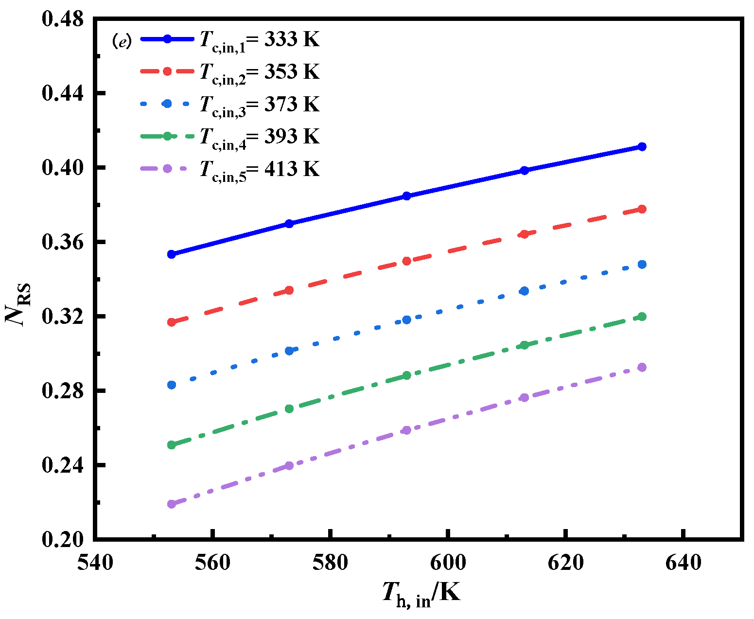
Firstly, the effects of the inlet temperature and inlet mass flow rate of molten salt are studied. Figure 3 shows the variation in ϕ g , N ED , R g , S g , and   N RS versus the inlet temperature of molten salt.
As can be seen from Figure 3a,d, when the inlet mass flow rate of molten salt is the same, ϕ g and S g increase with the increase in the inlet temperature. This is because the increasing of molten salt temperature increases the heat exchange temperature difference between the two working medium, and as irreversible loss increases,   ϕ g will increase. Furthermore,   ϕ g   and   S g increase as the mass flow rate increases, and when the mass flow rate increases, the heat transfer is intensified, making it easier to achieve heat transfer, and therefore the irreversible loss increases. In Figure 3b, the N ED decreases as the temperature of the molten salt inlet increases, as ϕ g , max increases more than ϕ g as the temperature of the molten salt inlet increases. When the inlet temperature is the same, N ED increases with the increase in mass flow rate, which is mainly caused by a larger increase in ϕ g than ϕ g , max . In Figure 3c, at the same mass flow rate of molten salt, R g decreases with the increase in inlet temperature, and when the inlet temperature is the same, R g decreases with the increase in mass flow rate, which is the result of the different growth rates of Q and ϕ g .
In Figure 3e, it can be seen that N RS increases with the increase in inlet temperature, because S g and Q both increase with the increase in inlet temperature, but S g has a larger increase than Q. At the same inlet temperature, N RS decreases with the increase in mass flow rate, which is caused by the larger increase in Q than S g .

3.1.2. The Effect of Inlet Temperature of sCO2

Figure 4 shows the variations in ϕ g , N ED , R g , S g , and   N RS in the heat exchanger with the inlet temperature of sCO2. As can be seen from Figure 4a,d, ϕ g and S g decrease with the increase in the inlet temperature of sCO2, because the increase in the inlet temperature of sCO2 reduces the heat transfer temperature difference between the two working media and the irreversible loss. When the inlet temperature of sCO2 remains unchanged, ϕ g and S g increase with the increase in the inlet temperature of molten salt, which is also caused by the increase in the heat exchange temperature difference between the two working fluids and the increase in irreversible loss. As show in Figure 4b,c, N ED and R g decrease with the increase in the inlet temperature of sCO2. This is because, as the inlet temperature of sCO2 increases, the values of ϕ g and ϕ g , max decrease, but ϕ g decreases more than ϕ g , max ; therefore, the values of N ED and R g decrease. When the inlet temperature of sCO2 remains unchanged, N E D   and   R g decrease with the increase in molten salt inlet temperature, and the temperature difference between the two fluids increases, so that ϕ g and ϕ g , max both increase, but ϕ g , max is larger than ϕ g ; therefore, N ED and R g will decrease accordingly. In Figure 4e, N RS decreases with the increase in the inlet temperature of sCO2, because with the increase in the sCO2 inlet temperature, both S g and Q decrease, but the value of S g decreases more than Q; therefore, N RS will decrease accordingly. When the inlet temperature of sCO2 remains unchanged, N RS increases with the increase in molten salt inlet temperature, because with the increase in the molten salt inlet temperature, both S g and Q increase, but S g increases more than Q; therefore, the value of N RS will increase accordingly.

3.1.3. The Effect of Inlet Mass Flow Rate of sCO2

Figure 5 shows the variation in ϕ g , N ED , R g , S g , and   N RS in the heat exchanger with the inlet mass flow rate of sCO2. The variation trend of the above five parameters with the inlet mass flow rate of sCO2 has many similarities with the variation trend of the inlet mass flow rate of molten salt in Section 3.1.1, and two differences will be explained here. The one is N ED , which shows the opposite trend in the two cases; that is, in Section 3.1.1, the calculation points are concentrated first and then scattered. Here, however, the calculation points are first scattered and then concentrated. The other difference is N RS , also showing the opposite trend in the two cases; that is, in Section 3.1.1, the molten salt inlet temperature is unchanged, and N RS decreases with the increase of molten salt mass flow rate. However, the inlet temperature of sCO2 remains unchanged, and N RS increases with the increase in mass flow rate of sCO2. This may be caused by the inconsistent effect of molten salt and sCO2 on enhancing heat transfer by increasing the inlet mass flow rate; the changes in irreversible losses are also inconsistent.

3.2. Thermodynamic Analysis under Constant Heat Flux

Constant heat flux means that the heat flux in the heat exchange process remains unchanged; the inlet and outlet temperatures and mass flow rates of the molten salt also remained unchanged, which were 613 K, 603 K, and 1 kgs−1, respectively.

3.2.1. The Effect of the Length of the Tube

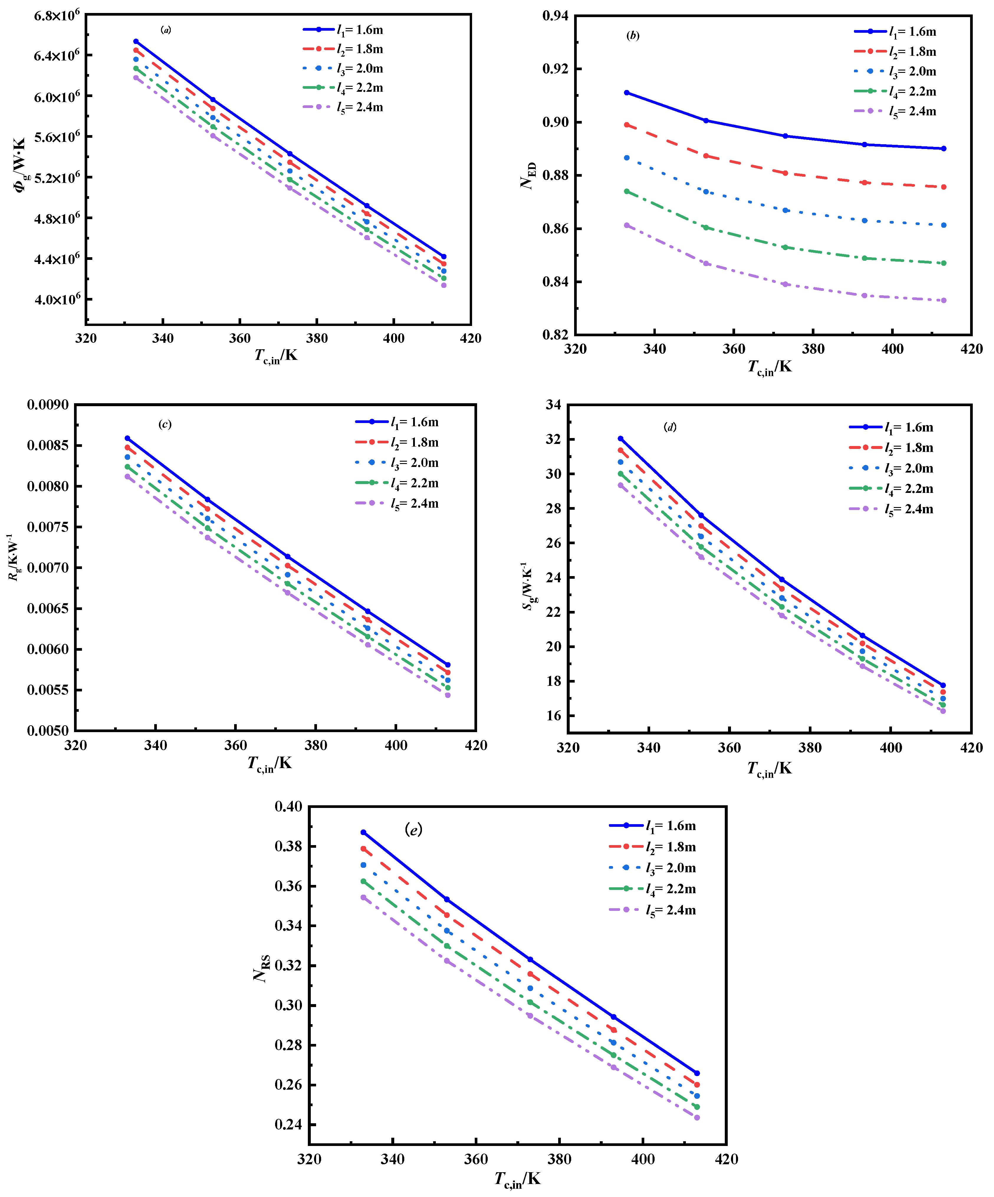
Figure 6 shows the variation in ϕ g , N ED , R g , S g , and   N RS in the heat exchanger with the length of the tube. It can be seen from Figure 6a,c,e that ϕ g , R g , and   N RS decrease with the increase in the sCO2 inlet temperature when the tube length is constant. When the sCO2 inlet temperature is constant, ϕ g , R g , and   N RS decrease with the increase in tube length. The shorter the tube length, the smaller the resistance in the tube. If the same heat flux is still to be maintained, the mass flow of sCO2 needs to be increased, resulting in enhanced heat transfer. The longer the tube length, the greater the resistance in the tube, and the more sufficient the heat exchange; therefore, it is not necessary to increase the mass flow of sCO2 to maintain the same heat flux. As a result, heat transfer is enhanced, irreversible losses increase, and ϕ g , R g , and   N RS also increase. It can be seen from Figure 6b,d that the tube length is constant, and N ED and S g decrease with the increase in the inlet temperature of sCO2. As the inlet temperature of CO2 increases, ϕ g and ϕ g , max decrease at the same time, but ϕ g decreases more than ϕ g , max ; therefore, N E D   and S g will decrease accordingly. At the same inlet temperature of sCO2, N ED decreases with increasing tube length. At the same inlet temperature of sCO2, ϕ g decreases with increasing tube length, so N ED and S g decrease accordingly.

3.2.2. The Effect of the Inner Diameter

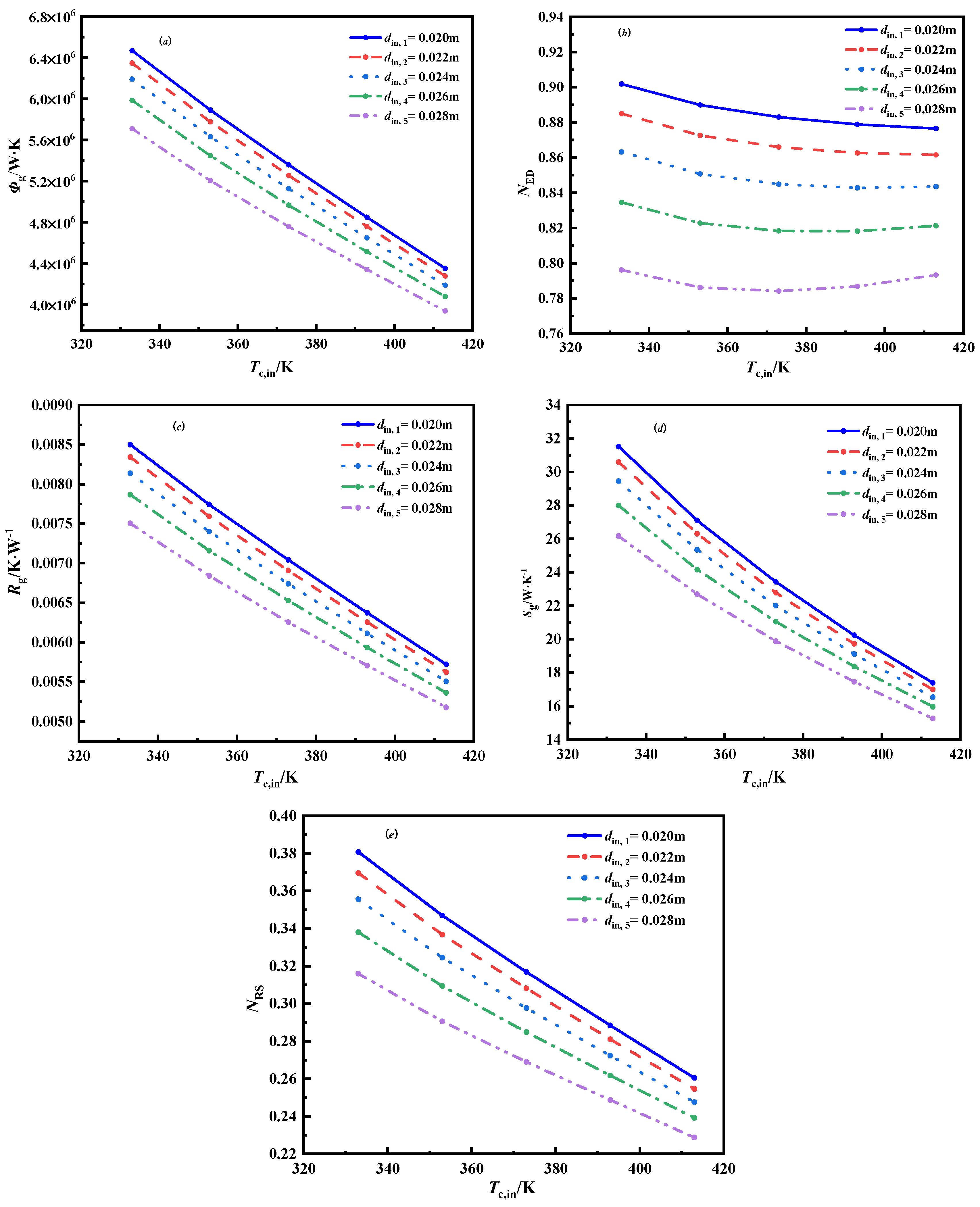
Figure 7 shows the variations in ϕ g , N ED , R g , S g , and   N RS in the heat exchanger with the inner diameter. In Figure 7a,c–e, when the inner diameter is the same, ϕ g , R g , S g , and N RS decrease with the increase of sCO2 inlet temperature. When the molten salt inlet parameters remain unchanged, the increase in the sCO2 inlet temperature reduces the heat transfer temperature difference between the two working fluids and the irreversible loss, and ϕ g , R g , Sg, and N RS will decrease accordingly. At the same sCO2 inlet temperature, ϕ g , R g , S g , and N RS decreases with the increase in inner diameter, the heat transfer area on the molten salt side increases with the increase in inner diameter, the heat transfer of the molten salt weakens when the mass flow rate of the molten salt remains unchanged, and the irreversible loss decreases; therefore, ϕ g , R g , S g , and N RS will decrease accordingly. It can be seen from Figure 7b that when the inner diameter is the same, N ED first decreases and then increases with the increase in sCO2 inlet temperature. As the inlet temperature of sCO2 increases, both ϕ g and ϕ g , max decrease, but there is an optimal sCO2 inlet temperature that makes the ratio of ϕ g and ϕ g , max reach an extreme value. At the same sCO2 inlet temperature, N ED decreases with the increase in inner diameter, the heat exchange area on the molten salt side increases when the inner diameter increases, and, when the mass flow on the molten salt side remains unchanged, the heat transfer on the molten salt side weakens. Both ϕ g and ϕ g , max decrease, but ϕ g decreases more than ϕ g , max ; therefore, N ED decreases accordingly.

3.2.3. The Effect of Outer Diameter

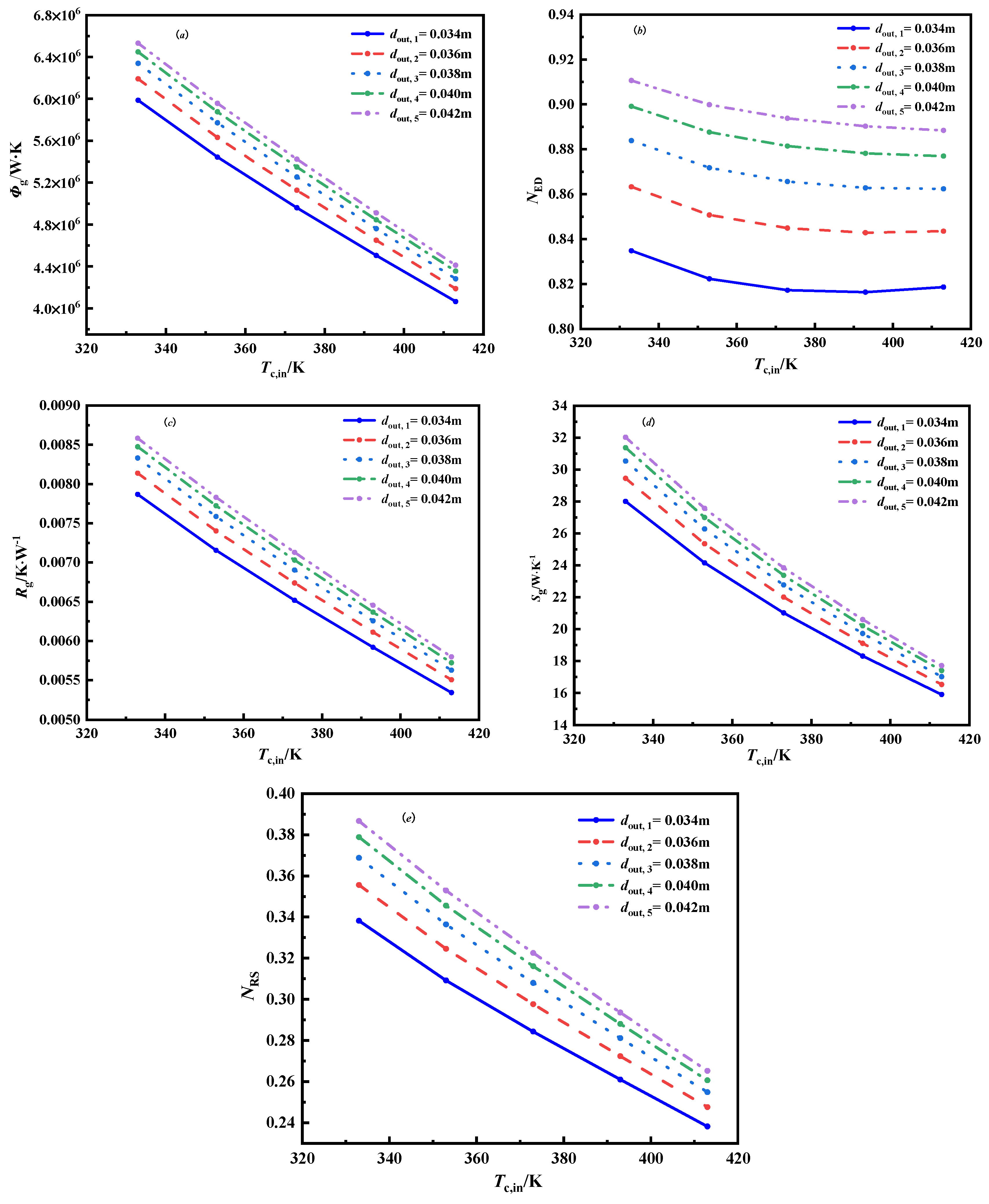
Figure 8 shows the variation in ϕ g , N ED , R g , S g , and   N RS in the heat exchanger with the outer diameter. At the same sCO2 inlet temperature, ϕ g , N ED , R g , S g , and   N RS increase with the increase in outer diameter, the heat transfer area on the sCO2 side increases with the increase in outer diameter, and the heat transfer of the sCO2 weakens when the mass flow rate of the sCO2 remains unchanged, and the irreversible loss increases; therefore, ϕ g , N ED , R g , S g , and   N RS will increase accordingly.

3.3. Optimization Analysis of the Concentric Tube Heat Exchanger

In this part, the geometric and operating parameters of the heat exchanger will be optimized and analyzed, and the optimized variables and ranges are shown in Table 3.

3.3.1. Single-Objective Optimization Analysis

The objective functions of the single-objective optimization calculation of the heat exchanger were measured using the following: ϕ g , N ED , R g , S g ,   N RS , Q, the pressure entransy dissipation number ( N P ), the total heat transfer coefficient (α), and heat transfer effectiveness (ε). The expression of N P , h, and ε are shown in Equations (17)–(19).
N P = m h Δ P h ρ h T h , out T h , in ln T h , out ln T h , in + m c Δ P c ρ c T c , out T c , in ln T c , out ln T c , in Q ( T h , in T c , in )
α = Q F Δ T m
where ΔTm is the logarithmic mean temperature difference, in K.
ε = max ( ( T h , in T h , out ) , ( T c , out T c , in ) ) T h , in T c , in
It will be discussed in two aspects: on the one hand, the corresponding results of each objective function are obtained; on the other hand, the values of other objective functions are calculated according to the optimization results of a certain objective function. The optimization results are shown in Table 4.
It can be seen from Table 4 that when the single-objective optimization calculation of the heat exchanger is performed for each objective function, each objective function corresponding to the variable range can obtain its own extreme value, but the corresponding other objective function values are not optimal. It shows that single-objective optimization has strong pertinence. In addition, if the heat exchange effectiveness (ε) is used as the evaluation index of the performance of the heat exchanger, the minimum ϕ g and S g are taken as the objective functions, meaning the heat exchange effectiveness is low and the effect is poor. However, with the N ED , R g , and N RS minimums as objective functions, a better optimization effect can be obtained, where the ε value is increased by 41.2%, 39.5%, and 40.3% compared with the reference individual.

3.3.2. Multi-Objective Optimization Analysis

The single-objective optimization results can ensure that the selected objective function obtains the extreme value; however, it cannot guarantee that the other performance parameters of the heat exchanger are ideal, which indicates that there is an opposite relationship between the objective functions. Since these objective functions can reflect certain aspects of the performance of a heat exchanger, the performance of some aspects of the heat exchanger can be improved, whereas the performance of other aspects will be suppressed. Different from single-objective optimization, the advantage of multi-objective optimization is that it can optimize the heat exchanger from multiple angles, so that each objective function in multi-objective optimization can obtain extreme values.
It can be seen from the single-objective optimization results that the optimization effect is better with the N ED , R g , and N RS minimums and ε maximum as the objective function; so, it was adopted in the multi-objective optimization. Np reflects the irreversible loss of the heat exchanger due to the flow resistance of the working medium. Therefore, the following multi-objective function combination was selected to optimize the casing heat exchanger, N ED and NP minimum, R g   and N P minimum, N RS and N P minimum, ε maximum, and N P minimum. The multi-objective optimization calculation results are shown in Table 5.
The corresponding multi-objective optimization calculation results were compared with the single-objective optimization calculation results, and the heat transfer effectiveness and pressure drop were used as indicators to evaluate the optimization calculation results. Compared with the reference, the heat exchange efficiency corresponding to the single-objective optimization results with the N ED , R g and N RS minimum and ε maximum as the objective functions have been improved to varying degrees, but the pressure drop of the working fluid has also increased, indicating that the improvement in heat transfer efficiency is achieved at the expense of an increasing pressure drop. Compared with the reference and single-objective optimization calculation results, the heat transfer efficiency of the multi-objective optimization calculation results is not as large as that of the single-objective optimization calculation results, and even the heat exchange efficiency is lower than that of the reference individual; but, the pressure drop in the tube is more obvious, which shows the opposite nature of each objective function in multi-objective optimization and the result of balancing the objective function. In addition, the comprehensive effect of the multi-objective optimization calculation results with the N RS and N P minimums as the objective function is optimal. Compared with the reference individual, the ε value increased by 23.5%, and Δ P h and Δ P c decreased by 51.9%, and 32.5%, respectively.

4. Conclusions

This paper takes a concentric tube heat exchanger as the research object, with molten salt and sCO2 used as the heat transfer medium, and performed thermodynamic and optimization calculations.
On the one hand, the thermodynamic analysis was carried out, by using the distributed parameter method, to model the heat exchanger and the effects of the structural parameters and operating parameters of the heat exchanger on the entransy dissipation rate, the entransy dissipation number, the entransy dissipation thermal resistance, entropy production rate and entropy production number. The results show that the structural parameters and operating parameters of the heat exchanger have different effects on the entropy dissipation, the entropy dissipation number, the entropy dissipation thermal resistance, the entropy production rate, and the entropy production number. Furthermore, the entransy dissipation rate and entropy production rate showed the same trend in structural parameters and operating parameters, and the changes in the entransy dissipation number and entransy dissipation thermal resistance were jointly affected by the entransy dissipation rate and the heat exchange.
On the other hand, single-objective and multi-objective optimizations were carried out, and it was found that single-objective optimization had strong pertinence, and the optimization results could only greatly improve the performance of a certain aspect of the heat exchanger. Taking the N ED , R g , and N RS minimums as the objective functions, the heat transfer efficiency was high, and the optimization effect was better. The ε values increased by 41.2%, 39.5%, and 40.3% compared with the reference individual. Multi-objective optimization can improve the limitations of single-objective optimization. From the perspective of improving comprehensive performance, the heat exchanger was optimized to keep the performance of the heat exchanger in balance. The multi-objective optimization calculation results with the N RS and N P minimums as the objective functions have more comprehensive, better results. Compared with the reference individual, the ε value increased by 23.5%, and Δ P h and Δ P c decreased by 51.9% and 32.5%, respectively.

Author Contributions

Methodology, Y.W., Y.L. and C.M.; Writing—original draft, X.D.; Writing—review & editing, C.Z. All authors have read and agreed to the published version of the manuscript.

Funding

This research was funded by [National Natural Science Foundation of China] grant number [51906003], [Science and technology general project of Beijing Municipal Education Commission] grant number [KM202210005016] and [the Inner Mongolia Science and Technology Major Project] grant number [2021ZD0036].

Data Availability Statement

The data used to support the findings of this study are available from the corresponding author upon request.

Conflicts of Interest

The authors declare no conflict of interest.

Nomenclature

Across-sectional area, m2Cthermal capacity, J·K−1
cpspecific heat capacity, J·kg−1·K−1dininner diameter, m
doutouter diameter, mDequivalent diameter, m
Ftotal heat exchange area, m2fthe resistance coefficient
hspecific enthalpy, J∙kg−1lthe length of heat exchanger, m
mmass flow rate, kg·s−1NuNusselt number
NEDentransy dissipation numberNRSimprove entropy production number
Nppressure entransy dissipation numberPpressure, Pa
ΔPpressure drop, PaPrPrandlt number
Qheat transfer rate, WReReynold number
Rgentransy dissipation thermal resistance, K·W−1Sgentropy production rate, W·K−1
sCO2supercritical CO2Ttemperature, K
ΔTtemperature difference, KΔTmlogarithmic mean temperature difference, K
uvelocity, m·s−1xx-direction component, m
Greek symbols
α heat transfer coefficient, W·m−2·K−1εheat transfer effectiveness
λthermal conductivity, W·m−1·K−1μdynamic viscosity, kg·m−1·s−1
ρdensity, kg·m−3ϕgentransy dissipation rate, W·K
Subscript
aveaverageccold
hhotininside
maxmaximumoutoutside
wwall

References

  1. Mehos, M.; Turchi, C.; Vidal, J. Concentrating Solar Power Gen 3 Demonstration Roadmap; Technical Report; NREL: Oslo, Norway, 2017. [Google Scholar]
  2. Han, Y.; Zhang, C.C.; Wu, Y.T.; Lu, Y.W. Investigation on thermal performance of quaternary nitrate-nitrite mixed salt and solar salt under thermal shock condition. Renw. Energyi. 2022, 175, 1041–1051. [Google Scholar] [CrossRef]
  3. Zhang, C.C.; Han, S.T.; Wu, Y.T.; Zhang, C.Y.; Guo, H. Investigation on convection heat transfer performance of quaternary mixed molten salt based nanofluids in smooth tube. Int. J. Therm. Sci. 2022, 177, 107534. [Google Scholar] [CrossRef]
  4. Bhuvaneswari, S.; Elatharasan, G. A Study of the Literature Review on Heat Transfer in A Helically Coiled Heat Exchanger. Int. J. Eng. Res. Technol. 2019, 7, 1–3. [Google Scholar]
  5. Mylavarapu, S.K.; Figley, J.; Sun, X.; Christensen, R.N.; Needler, N.J.; Hajek, B.K. Development and testing of printed circuit heat exchanger for generation IV reactors. Trans. Am. Nucl. Soc. 2008, 98, 626–627. [Google Scholar]
  6. Bejan, A. Entropy Generation Minimization: The New Thermodynamics of Finite-Size Devices and Finite-Time Processes. J. Appl. Phys. 1996, 79, 1191–1218. [Google Scholar] [CrossRef] [Green Version]
  7. Bejan, A. Second-Law Analysis in Heat Transfer and Thermal Design; Elsevier: New York, NY, USA, 1982; pp. 1–58. [Google Scholar]
  8. Hesselgreaves, J.E. Rationalisation of second law analysis of heat exchangers. Int. J. Heat Mass Transf. 2000, 43, 4189–4204. [Google Scholar] [CrossRef]
  9. Ogiso, K. Duality of heat exchanger performance in balanced counter-flow systems. J. Heat Transf.-Trans. AMSE 2003, 125, 530–532. [Google Scholar] [CrossRef]
  10. Shah, R.K.; Skiepko, T. Entropy generation extrema and their relationship with heat exchanger effectiveness-number of transfer unit behavior for complex flow arrangements. J. Heat Transf.-Trans. AMSE 2004, 126, 994–1002. [Google Scholar] [CrossRef]
  11. Guo, Z.Y.; Zhu, H.Y.; Liang, X.G. Entransy: A Physical Quantity Describing Heat Transfer Ability. Int. J. Heat Mass Transf. 2007, 50, 2545–2556. [Google Scholar] [CrossRef]
  12. Guo, F.; Cheng, L.; Xu, M.T. Entransy Dissipation Number and Its Application to Heat Exchanger Performance Evaluation. Chin. Sci. Bull. 2009, 54, 2998–3002. [Google Scholar] [CrossRef]
  13. Lerou, P.P.P.M.; Veenstra, T.T.; Burger, J.F.; ter Brake, H.J.; Rogalla, H. Optimization of counterflow heat exchanger geometry through minimization of entropy generation. Cryogenics 2005, 45, 659–669. [Google Scholar] [CrossRef]
  14. Chen, Q. Entransy dissipation-based thermal resistance method for heat exchanger performance design and optimization. Int. J. Heat Mass Transf. 2013, 60, 156–162. [Google Scholar] [CrossRef]
  15. Wang, S.M.; Jian, G.P.; Sun, J.R. Application of entransy-dissipation-based thermal resistance for performance optimization of spiral-wound heat exchanger. Int. J. Heat Mass Transf. 2018, 116, 743–750. [Google Scholar] [CrossRef]
  16. Guo, J.F.; Xu, M.T. The application of entransy dissipation theory in optimization design of heat exchanger. Appl. Therm. Eng. 2012, 36, 227–235. [Google Scholar] [CrossRef]
  17. Qian, X.D.; Li, X.Z. Analysis of entransy dissipation in heat exchangers. Int. J. Therm. Sci. 2011, 50, 608–614. [Google Scholar] [CrossRef]
  18. Cheng, X.T.; Zhang, Q.Z.; Liang, X.G. Analyses of entransy dissipation, entropy generation and entransy-dissipation-based thermal resistance on heat exchanger optimization. Appl. Therm. Eng. 2012, 38, 31–39. [Google Scholar] [CrossRef]
  19. Liu, X.B.; Meng, J.A.; Guo, Z.Y. Entropy generation extremum and entransy dissipation extremum for heat exchanger optimization. Chin. Sci. Bull. 2009, 54, 943–947. [Google Scholar] [CrossRef]
  20. Guo, J.F.; Xu, M.T.; Cheng, L. Principle of equipartition of entransy dissipation for heat exchanger design. Sci China Tech Sci 2010, 53, 1309–1314. [Google Scholar] [CrossRef]
  21. Xie, G.N.; Song, Y.D.; Asadi, M.; Lorenzini, G. Optimization of Pin-Fins for a Heat Exchanger by Entropy Generation Minimization and Constructal Law. J. Heat Transf. Trans. Asme 2015, 137, 1–9. [Google Scholar] [CrossRef]
  22. Guo, Z.Y.; Liu, X.B.; Tao, W.Q. Effectiveness–thermal resistance method for heat exchanger design and analysis. International J. Heat Mass Transf. 2010, 53, 2877–2884. [Google Scholar] [CrossRef]
  23. Li, K.; Wen, J.; Liu, Y.C.; Liu, H.; Wang, S.; Tu, J. Application of entransy theory on structure optimization of serrated fin in plate-fin heat exchanger. Appl. Therm. Eng. 2020, 173, 114809. [Google Scholar] [CrossRef]
  24. Han, Z.X.; Guo, J.F.; Huai, X.L. Research on optimization method of new airfoil heat exchanger based on entransy dissipation theory. Chin. Sci. Technol. Sci. 2021, 51, 1219–1230. [Google Scholar]
  25. Han, Y.; Zhang, C.C.; Zhu, Y.J.; Wu, X.H.; Jin, T.X.; Li, J.N. Investigation of heat transfer Exergy loss number and its application in optimization for the shell and helically coiled tube heat exchanger. Appl. Therm. Eng. 2022, 211, 118424. [Google Scholar] [CrossRef]
  26. Linstrom, P.J.; Mallard, W.G. National Institute of Standards and Technology: Gaithersburg, MD, USA, 2005, 2011. Available online: http://webbook.nist.gov/chemistry (accessed on 5 September 2022).
  27. Gnielinski, V. New Equations for Heat and Mass Transfer in Turbulent Pipe and Channel Flows. Int. J. Chem. Eng. 1976, 16, 359–368. [Google Scholar]
  28. Hall, W.B.; Jackson, J.D.; Watson, A. Forced convection heat transfer to fluids at supercritical pressure. In Turbulent Forced Convection in Channels and Bundles; Hemisphere: New York, NY, USA, 1979; Volume 2, pp. 563–611. [Google Scholar]
  29. Chen, H.; Chen, X.; Wu, Y.T.; Lu, Y.W.; Wang, X.; Ma, C.F. Experimental study on forced convection heat transfer of KNO3–Ca(NO3)2 + SiO2 molten salt nanofluid in circular tube. Sol. Energy 2020, 206, 900–906. [Google Scholar] [CrossRef]
Figure 1. The schematic diagram of the concentric tube heat exchanger.
Energies 15 07398 g001
Figure 2. The thermal property parameters of molten salt and sCO2.
Energies 15 07398 g002
Figure 3. The ϕ g (a), N ED (b), R g (c), S g (d), and   N RS (e) versus the inlet temperature of molten salt.
Energies 15 07398 g003
Figure 4. The ϕ g (a), N ED (b), R g (c), S g (d), and   N RS (e) versus the inlet temperature of sCO2.
Energies 15 07398 g004aEnergies 15 07398 g004b
Figure 5. The ϕ g (a), N ED (b), R g (c), S g (d), and   N RS (e) versus the inlet mass flow rate of sCO2.
Energies 15 07398 g005aEnergies 15 07398 g005b
Figure 6. The ϕ g (a), N ED (b), R g (c), S g (d), and   N RS (e) versus the length of the tube.
Energies 15 07398 g006
Figure 7. The ϕ g (a), N ED (b), R g (c), S g (d), and   N RS (e) versus the inner diameter.
Energies 15 07398 g007
Figure 8. The ϕ g (a), N ED (b), R g (c), S g (d), and   N RS (e) versus the outer diameter.
Energies 15 07398 g008
Table 1. The element independence verification.
Number of Elements T h , o u t / K T c , o u t / K
50617.83423.84
100617.83423.85
150617.83423.85
200617.83423.85
300617.83423.85
500617.83423.85
Table 2. Comparison between simulation results and experimental results.
Fluidsd/m l/m T i n / K m i n / kg / s T o u t / K EXP . [29] T o u t / K Numerical Deviation
Molten salt0.021623.950.86615.45617.830.39%
oil0.0341425.350.465425.35423.840.36%
Table 3. Optimized parameters and ranges.
ParametersRangesParametersRanges
d in /m0.015–0.035 d out /m0.030–0.050
l /m1.6–2.4 T h , in /K543.15–583.15
T c , in /K323.15–363.15 m h /kg/s0.8–1.0
m c /kg/s1.0–1.2
Table 4. Single-objective optimization calculation results.
Single Objective Optimization Objective Function
Ref m i n ( ϕ g ) m i n ( N E D ) m i n ( R g ) m i n ( S g ) m i n ( N R S ) m i n ( N P ) max ( α ) m a x ( Q ) max ( ε )
d in /m0.020.0150.0170.0180.0150.020.0220.0150.0150.017
d out /m0.0340.050.0310.0320.050.0340.050.030.030.031
l /m21.62.42.3971.62.41.6471.6092.42.4
T h , in /K563.15543.15583.14583.12543.15543.15574.31583.13583.15583.15
T c , in /K343.15346.15363.15363.14363.15363.15323.25363.14323.15363.15
m h /kg/s0.80.80.80.9990.80.9980.839111
m c kg/s1.2111.19911.0011.0241.21.21.001
ϕ g 7,491,0971,798,0478,245,2139,817,4591,798,0475,624,9944,919,7997,083,19314,124,1538,985,178
N ED 0.8910.9570.8490.8540.9570.8620.9570.9010.8910.850
S g 0.005130.016510.004230.003590.016510.004280.011740.005540.003800.00390
R g 38.4969.07438.13645.3769.07427.96026.48432.95074.51141.263
N RS 0.3460.3160.3140.3150.3160.2800.4180.3350.3950.312
N P 9.17 × 10−63.08 × 10−61.14 × 10−51.49 × 10−53.08 × 10−61.24 × 10−54.64 × 10−71.44 × 10−55.98 × 10−61.13 × 10−5
h 1563.287804.27321867.8392079.548804.27321565.425749.12982391.5152207.7222027.949
Q /W38,213.3310,437.4144,146.852,291.3410,437.4136,248.6120,467.8435,746.2260,983.5748,021.55
ε 0.1190.0460.1680.1660.0460.1670.0530.1120.1280.183
Table 5. Multi-objective optimization calculation results.
Single-Objective Optimization Objective FunctionMulti-Objective Optimization Objective Function
Ref m i n ( N E D ) m i n ( R g ) m i n ( N R S ) max ( ε ) min ( N E D )
+
m i n ( N P )
m i n ( R g )
+
m i n ( N P )
m i n ( N R S )
+
m i n ( N P )
max ( ε )
+
m i n ( N P )
d in /m0.020.0170.0180.020.0170.02130.02850.02550.0208
d out /m0.0340.0310.0320.0340.0310.0350.0430.0400.035
l /m22.42.3972.42.42.3982.3922.3972.361
T h , in /K563.15583.14583.11543.152583.15547.17566.59543.21566.39
T c , in /K343.15363.15363.14363.14363.15344.65324.149363.15323.60
m h   kg / s 0.80.80.9990.99810.99310.8940.820
m c kg/s1.211.1991.0011.0011.0211.1711.0161.182
ϕ g 7,491,0978,245,2139,817,4595,624,9948,985,1787,188,21010,923,8445,113,36110,479,204
N ED 0.8910.8490.8540.8620.8500.8750.9030.8720.896
S g 0.005130.0042310.003590.0042810.0038960.0043660.0043890.0048180.004516
R g 38.49638.13645.37627.96041.26337.44359.19725.52457.252
N RS 0.3456920.3140.3150.2800.3120.3180.3850.2850.385
N P 9.17 × 10−61.14 × 10−51.49 × 10−51.24 × 10−51.13 × 10−57.28 × 10−62.74 × 10−69.34 × 10−64.27 × 10⁻⁶
α 1563.2871867.8392079.5481565.4252027.9491441.7611071.8111091.0821449.806
Q /W38,213.3344,146.852,291.3436,248.6148,021.5540,577.4549,887.3932,577.8848,170.41
ε 0.1190.1680.1660.16760.18360.1460.1130.1470.133
Δ P h 5.01712.58037.6079.21228.0916.6891.6282.4145.163
Δ P c 28.91114.08448.75918.51638.89324.53916.15519.51124.305
Publisher’s Note: MDPI stays neutral with regard to jurisdictional claims in published maps and institutional affiliations.