
Design of Battery Thermal Management System with Considering the Longitudinal and Transverse Temperature Difference

Abstract
:1. Introduction
2. Model
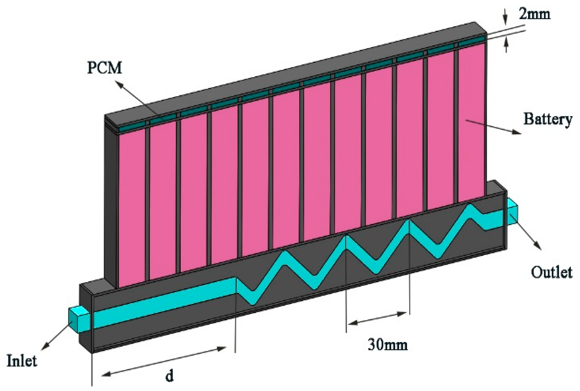
2.1. Geometry
2.2. Equations and Boundary Conditions
2.3. Model Validation
3. Results and Discussion
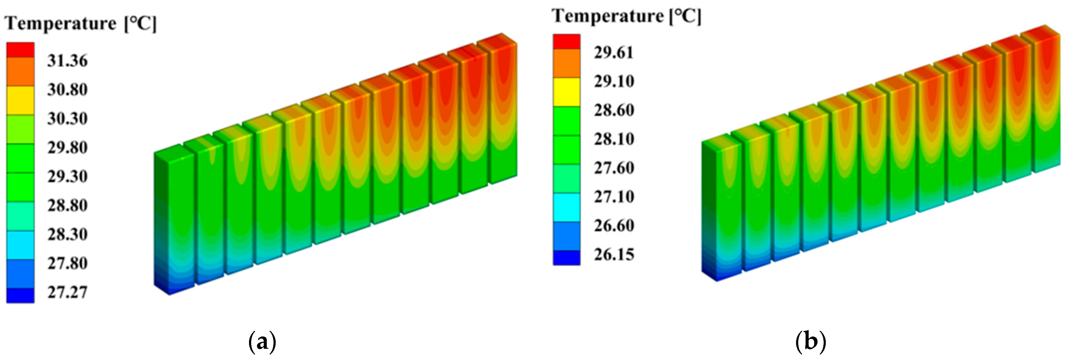
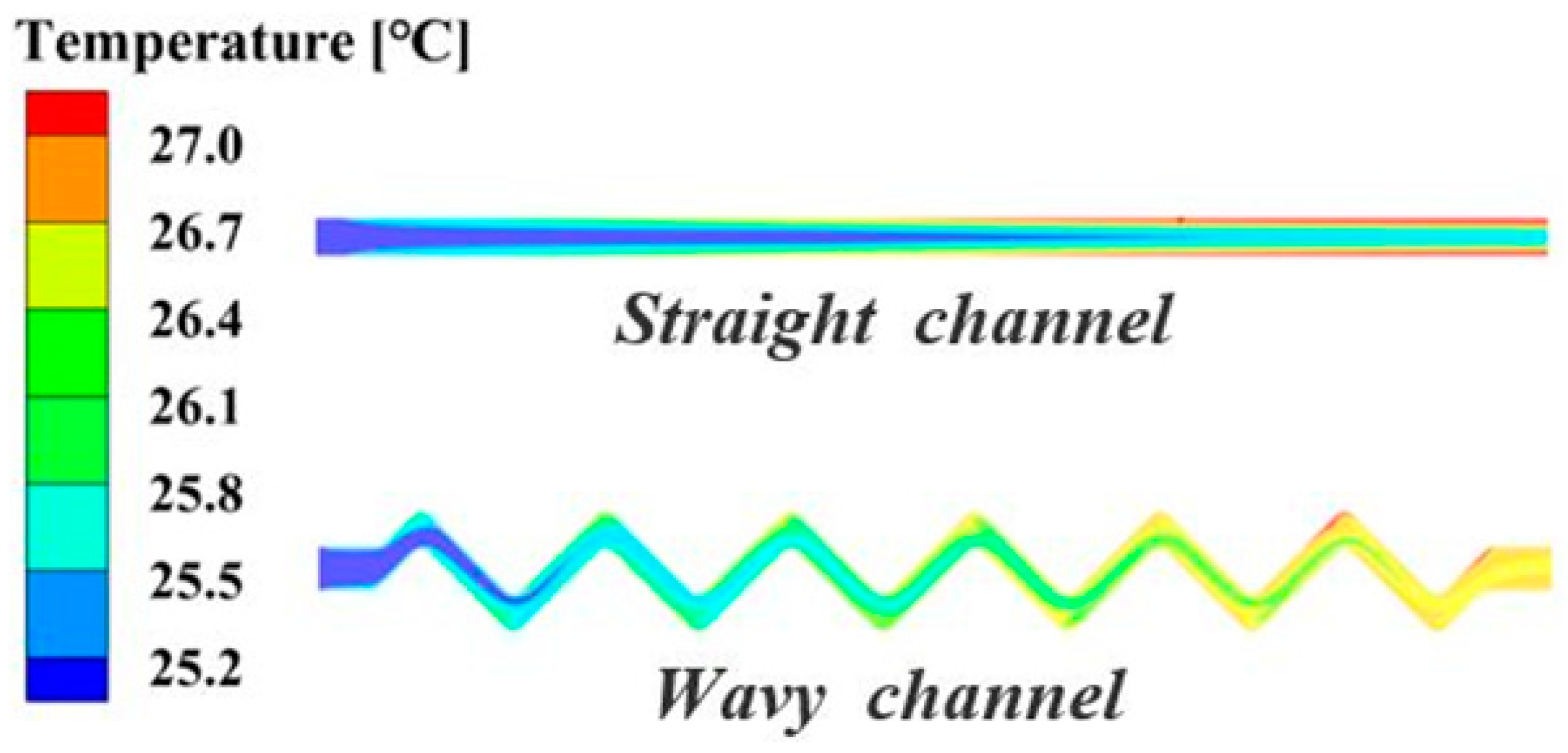
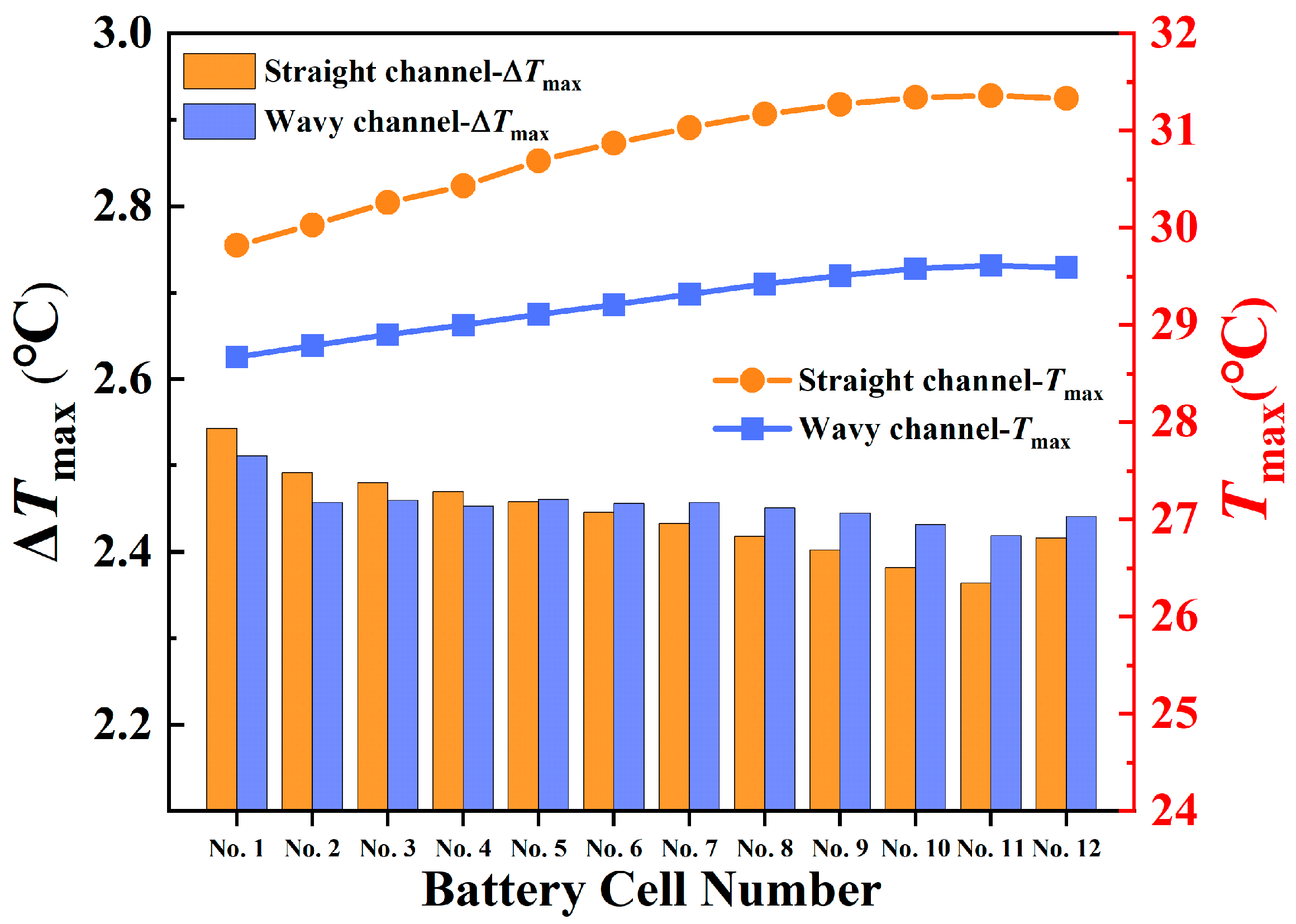
3.1. Wavy-Channel Design
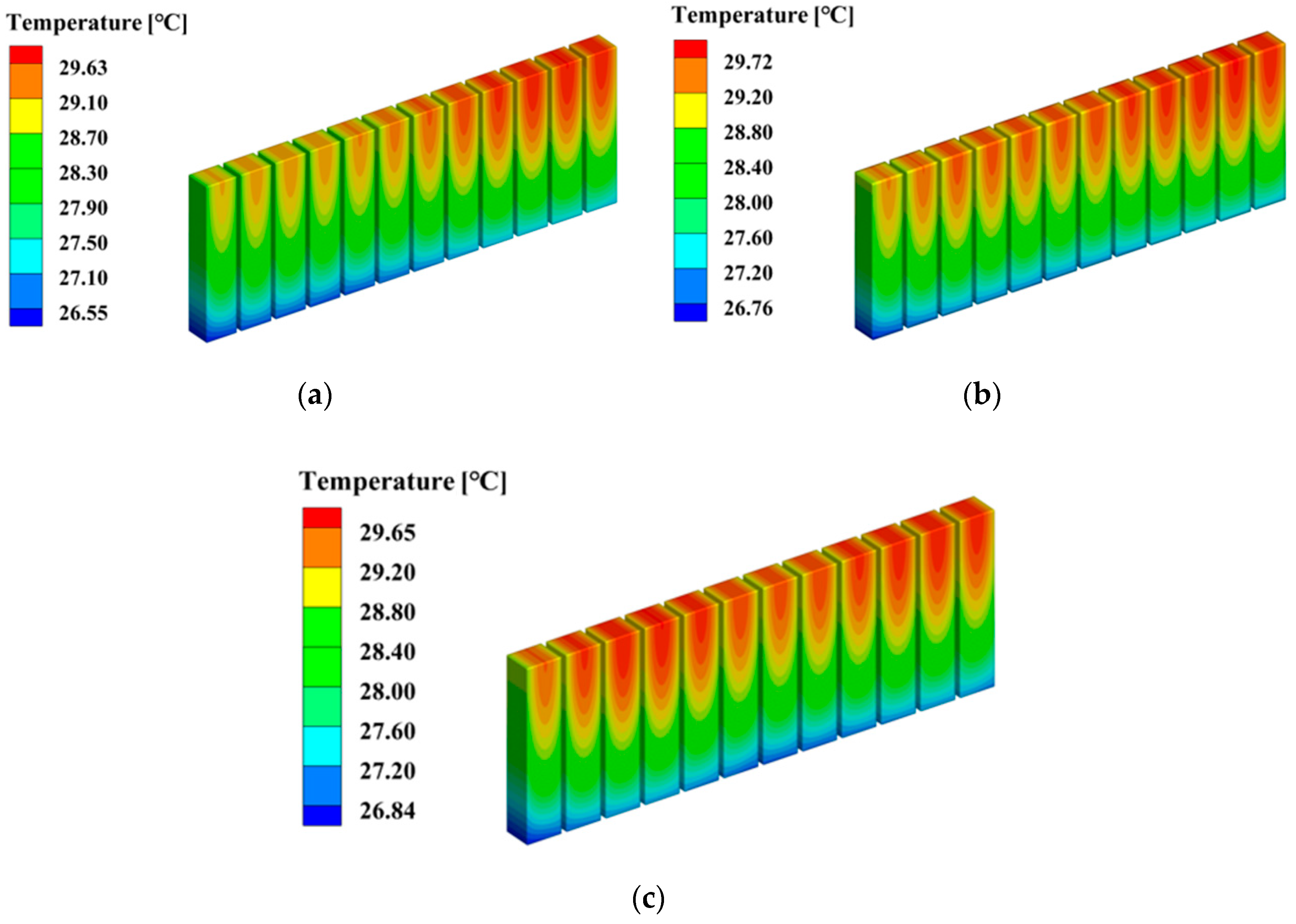
3.2. Composite-Channel Design
3.3. Composite-Channel/PCM Design
4. Conclusions and Future Work
- (1)
- The wavy-channel design significantly strengthens the heat transfer between the battery bottom and the cold plate. The maximum battery module temperature Tgmax for the wavy channel is 29.61 °C, a reduction of 1.75 °C compared to the straight-channel design.
- (2)
- The composite-channel design significantly enhances the temperature uniformity between batteries.
- (3)
- The straight-channel length in the composite channel has a significant effect on the maximum temperature difference in the battery module.
- (4)
- Adding the PCM to the top of the battery significantly reduces the maximum temperature of the batteries, which in turn improves the temperature uniformity in the height direction of the battery.
Author Contributions
Funding
Conflicts of Interest
References
- Sarchami, A.; Najafi, M.; Imam, A.; Houshfar, E. Experimental study of thermal management system for cylindrical Li-ion battery pack based on nanofluid cooling and copper sheath. Int. J. Therm. Sci. 2022, 171, 1–10. [Google Scholar] [CrossRef]
- Mo, C.; Zhang, G.; Yang, X.; Wu, X.; Li, X. A Battery Thermal Management System Coupling High-Stable Phase Change Material Module with Internal Liquid Cooling. Energies 2022, 15, 5863. [Google Scholar] [CrossRef]
- Xu, Z.; Xu, J.; Guo, Z.; Wang, H.; Sun, Z.; Mei, X. Design and Optimization of a Novel Microchannel Battery Thermal Management System Based on Digital Twin. Energies 2022, 15, 1421. [Google Scholar] [CrossRef]
- Chen, K.; Wu, W.; Yuan, F.; Chen, L.; Wang, S. Cooling efficiency improvement of air-cooled battery thermal management system through designing the flow pattern. Energy 2019, 167, 781–790. [Google Scholar] [CrossRef]
- Wang, M.; Hung, T.-C.; Xi, H. Numerical Study on Performance Enhancement of the Air-Cooled Battery Thermal Management System by Adding Parallel Plates. Energies 2021, 14, 3096. [Google Scholar] [CrossRef]
- Chen, Y.; Chen, K.; Dong, Y.; Wu, X. Bidirectional symmetrical parallel mini-channel cold plate for energy efficient cooling of large battery packs. Energy 2022, 242, 122553. [Google Scholar] [CrossRef]
- Zhou, Y.; Wang, Z.; Xie, Z.; Wang, Y. Parametric Investigation on the Performance of a Battery Thermal Management System with Immersion Cooling. Energies 2022, 15, 2554. [Google Scholar] [CrossRef]
- Jilte, R.; Afzal, A.; Panchal, S. A novel battery thermal management system using nano-enhanced phase change materials. Energy 2021, 219, 119564. [Google Scholar] [CrossRef]
- Jin, X.; Duan, X.; Jiang, W.; Wang, Y.; Zou, Y.; Lei, W.; Sun, L.; Ma, Z. Structural design of a composite board/heat pipe based on the coupled electro-chemical-thermal model in battery thermal management system. Energy 2021, 216, 119234. [Google Scholar] [CrossRef]
- Zhuang, Y.; Chen, T.; Chen, J.; Li, J.; Guan, M.; Chen, Y. Thermal uniformity performance of a hybrid battery thermal management system using phase change material and cooling plates arrayed in the manner of honeycomb. Therm. Sci. Eng. Prog. 2021, 26, 101094. [Google Scholar] [CrossRef]
- Joula, M.; Dilibal, S.; Mafratoglu, G.; Danquah, J.O.; Alipour, M. Hybrid Battery Thermal Management System with NiTi SMA and Phase Change Material (PCM) for Li-ion Batteries. Energies 2022, 15, 4403. [Google Scholar] [CrossRef]
- Yin, B.; Zuo, S.; Xu, Y.; Chen, S. Performance of liquid cooling battery thermal management system in vibration environment. J. Energy Storage 2022, 53, 105232. [Google Scholar] [CrossRef]
- Qian, Z.; Li, Y.; Rao, Z. Thermal performance of lithium-ion battery thermal management system by using mini-channel cooling. Energy Convers. Manag. 2016, 126, 622–631. [Google Scholar] [CrossRef]
- Rao, Z.; Zhang, X. Investigation on thermal management performance of wedge-shaped microchannels for rectangular Li-ion batteries. Int. J. Energy Res. 2019, 43, 3876–3890. [Google Scholar] [CrossRef]
- Kong, W.; Zhu, K.; Lu, X.; Jin, J.; Ni, M. Enhancement of lithium-ion battery thermal management with the divergent-shaped channel cold plate. J. Energy Storage 2021, 42, 103027. [Google Scholar] [CrossRef]
- Sheng, L.; Su, L.; Zhang, H.; Li, K.; Fang, Y.; Ye, W.; Fang, Y. Numerical investigation on a lithium ion battery thermal management utilizing a serpentine-channel liquid cooling plate exchanger. Int. J. Heat Mass Transf. 2019, 141, 658–668. [Google Scholar] [CrossRef]
- Deng, T.; Zhang, G.; Ran, Y.; Liu, P. Thermal performance of lithium ion battery pack by using cold plate. Appl. Therm. Eng. 2019, 160, 114088. [Google Scholar] [CrossRef]
- Ding, Y.; Ji, H.; Wei, M.; Liu, R. Effect of liquid cooling system structure on lithium-ion battery pack temperature fields. Int. J. Heat Mass Transf. 2022, 183, 122178. [Google Scholar] [CrossRef]
- Xu, H.; Zhang, X.; Xiang, G.; Li, H. Optimization of liquid cooling and heat dissipation system of lithium-ion battery packs of automobile. Case Stud. Therm. Eng. 2021, 26, 101012. [Google Scholar] [CrossRef]
- Xu, X.; Tong, G.; Li, R. Numerical study and optimizing on cold plate splitter for lithium battery thermal management system. Appl. Therm. Eng. 2020, 167, 114787. [Google Scholar] [CrossRef]
- Chung, Y.; Kim, M.S. Thermal analysis and pack level design of battery thermal management system with liquid cooling for electric vehicles. Energy Convers. Manag. 2019, 196, 105–116. [Google Scholar] [CrossRef]
- Li, Y.; Guo, H.; Qi, F.; Guo, Z.; Li, M.; Bertling Tjernberg, L. Investigation on liquid cold plate thermal management system with heat pipes for LiFePO4 battery pack in electric vehicles. Appl. Therm. Eng. 2021, 185, 116382. [Google Scholar] [CrossRef]
- Deng, T.; Ran, Y.; Zhang, G.; Yin, Y. Novel leaf-like channels for cooling rectangular lithium ion batteries. Appl. Therm. Eng. 2019, 150, 1186–1196. [Google Scholar] [CrossRef]
- Alnaqi, A.A. Numerical analysis of pressure drop and heat transfer of a Non-Newtonian nanofluids in a Li-ion battery thermal management system (BTMS) using bionic geometries. J. Energy Storage 2022, 45, 103670. [Google Scholar] [CrossRef]
- Li, B.; Wang, W.; Bei, S.; Quan, Z. Analysis of Heat Dissipation Performance of Battery Liquid Cooling Plate Based on Bionic Structure. Sustainability 2022, 14, 5541. [Google Scholar] [CrossRef]
- Liu, X.; Sun, A.; Tian, C. Research on liquid cooling and heat dissipation of lithium-ion battery pack based on bionic wings vein channel cold plate. Energy Storage Sci. Technol. 2022, 11, 2266–2273. [Google Scholar]
- Fan, Y.; Wang, Z.; Fu, T.; Wu, H. Numerical investigation on lithium-ion battery thermal management utilizing a novel tree-like channel liquid cooling plate exchanger. Int. J. Heat Mass Transf. 2022, 183, 122143. [Google Scholar] [CrossRef]
- Ran, Y.; Su, Y.; Chen, L.; Yan, K.; Yang, C.; Zhao, Y. Investigation on thermal performance of water-cooled Li-ion cell and module with tree-shaped channel cold plate. J. Energy Storage 2022, 50. [Google Scholar] [CrossRef]
- Mo, X.; Zhi, H.; Xiao, Y.; Hua, H.; He, L. Topology optimization of cooling plates for battery thermal management. Int. J. Heat Mass Transf. 2021, 178, 121612. [Google Scholar] [CrossRef]
- Yan, S.; Wang, F.; Hong, J.; Sigmund, O. Topology optimization of microchannel heat sinks using a two-layer model. Int. J. Heat Mass Transf. 2019, 143. [Google Scholar] [CrossRef]
- Guo, R.; Li, L. Heat dissipation analysis and optimization of lithium-ion batteries with a novel parallel-spiral serpentine channel liquid cooling plate. Int. J. Heat Mass Transf. 2022, 189. [Google Scholar] [CrossRef]
- Pety, S.J.; Tan, M.H.Y.; Najafi, A.R.; Barnett, P.R.; Geubelle, P.H.; White, S.R. Carbon fiber composites with 2D microvascular networks for battery cooling. Int. J. Heat Mass Transf. 2017, 115, 513–522. [Google Scholar] [CrossRef]
- Mallya, N.; Haussener, S. Buoyancy-driven melting and solidification heat transfer analysis in encapsulated phase change materials. Int. J. Heat Mass Transf. 2021, 164, 120525. [Google Scholar] [CrossRef]
- Zhang, F.; Yi, M.; Wang, P.; Liu, C. Optimization design for improving thermal performance of T-type air-cooled lithium-ion battery pack. J. Energy Storage 2021, 44, 103464. [Google Scholar] [CrossRef]
- Tete, P.R.; Gupta, M.M.; Joshi, S.S. Numerical investigation on thermal characteristics of a liquid-cooled lithium-ion battery pack with cylindrical cell casings and a square duct. J. Energy Storage 2022, 48, 104041. [Google Scholar] [CrossRef]
- Wang, R.; Liang, Z.; Souri, M.; Esfahani, M.N.; Jabbari, M. Numerical analysis of lithium-ion battery thermal management system using phase change material assisted by liquid cooling method. Int. J. Heat Mass Transf. 2022, 183, 122095. [Google Scholar] [CrossRef]
- Lamrani, B.; Lebrouhi, B.E.; Khattari, Y.; Kousksou, T. A simplified thermal model for a lithium-ion battery pack with phase change material thermal management system. J. Energy Storage 2021, 44, 103377. [Google Scholar] [CrossRef]


| Parameters | PCM (RT27) | Battery | Aluminum | Coolant |
|---|---|---|---|---|
| Specific heat capacity (J kg−1 K−1) | 2400 (Solid Phase) 1800 (Liquid Phase) | 1633 | 871 | 4182 |
| Thermal conductivity (W m−1 K−1) | 0.24 (Solid Phase) 0.15 (Liquid Phase) | 29/29/1 | 202.4 | 0.6 |
| Density (kg m−3) | 870 (Solid Phase) 760 (Liquid Phase) | 2136.8 | 2719 | 998.2 |
| Viscosity of liquid phase (kg m−1 s−1) | 0.00324 | 0.001003 | ||
| Latent heat of phase change of PCM (J kg−1 K−1) | 179,000 | |||
| Phase change temperature (°C) | 28 | |||
| Phase change interval (°C) | 2 |
| Mesh 1 | Mesh 2 | Mesh 3 | Mesh 4 | Mesh 5 | |
|---|---|---|---|---|---|
| Number of meshes | 414640 | 845958 | 1313585 | 2524904 | 3041312 |
Publisher’s Note: MDPI stays neutral with regard to jurisdictional claims in published maps and institutional affiliations. |
© 2022 by the authors. Licensee MDPI, Basel, Switzerland. This article is an open access article distributed under the terms and conditions of the Creative Commons Attribution (CC BY) license (https://creativecommons.org/licenses/by/4.0/).
Share and Cite
Dong, J.; Lu, X.; Sun, Y.; Mitin, V.; Xu, H.; Kong, W. Design of Battery Thermal Management System with Considering the Longitudinal and Transverse Temperature Difference. Energies 2022, 15, 7448. https://doi.org/10.3390/en15197448
Dong J, Lu X, Sun Y, Mitin V, Xu H, Kong W. Design of Battery Thermal Management System with Considering the Longitudinal and Transverse Temperature Difference. Energies. 2022; 15(19):7448. https://doi.org/10.3390/en15197448
Chicago/Turabian StyleDong, Junhao, Xipo Lu, Yang Sun, Vladislav Mitin, Huaping Xu, and Wei Kong. 2022. "Design of Battery Thermal Management System with Considering the Longitudinal and Transverse Temperature Difference" Energies 15, no. 19: 7448. https://doi.org/10.3390/en15197448