Abstract
In the drilling of horizontal wells, the drill cuttings tend to settle down on the low side of the annulus due to gravity and form a stationary bed, which results in hole cleaning problems. In this paper, a novel type of drillpipe with an elliptical shape was proposed to alleviate inadequate hole cleaning during the drilling of horizontal wells. A three-dimensional computational fluid dynamic (CFD) Eulerian-Eulerian approach with the Realizable k-ɛ turbulence model was developed to predict the solid–liquid two-phase flow in the annular space. Numerical examples were given to investigate the influence of different parameters on cuttings’ transport behavior, and the elliptical drillpipe was compared with the circular drillpipe. The annular cuttings concentration, annular pressure drop, and hole cleaning efficiency were evaluated. The numerical results clarify the potential of the elliptical drillpipe to enhance the hole cleaning efficiency without significantly increasing the annular pressure drop. Due to the swirl flow and secondary flow caused by the rotation of the curvature wall, the swaying phenomenon of drill cuttings’ distribution along the rotation direction of drillpipe was observed and enhanced the cuttings transport ability. Using the elliptical drillpipe as a joint-type tool can improve hole cleaning performance. Under the optimum conditions applied in this study, the hole cleaning efficiency increased by nearly 18%.
1. Introduction
With the rapid development of the world economy, energy demands are increasing. Oil and gas are still vital energy resources to ensure human survival and development over a sufficiently long time [1,2]. When compared with conventional drilling methods, the horizontal well has more advantages in improving well production and reducing costs. Horizontal well technology has broad application prospects in oil and gas reservoir exploration and development [3,4,5,6,7].
When drilling long horizontal wells, the drill cuttings tend to deposit on the low side of the annulus and form a stationary bed, causing hole-cleaning problems. Inadequate hole cleaning can cause downhole safety accidents, such as pipes becoming stuck, premature bit wear, slow rate of penetration (ROP), formation fracturing, excessive torque and drag on the drillstring, as well as difficulties in logging and cementing. Inadequate removal of drill cuttings is a primary challenge in horizontal well drilling and may increase the cost and risk of drilling while increasing the non-productive time (NPT) [3,8,9,10,11,12,13,14]. Therefore, it is essential to effectively alleviate inadequate hole cleaning during horizontal well drilling.
In the last decades, the cuttings transport phenomenon in the wellbore annulus has been extensively investigated. The results of previous studies show that many interdependent factors and the inherent complexity of the transport process pose challenges to efficient hole cleaning [15]. There are four groups of parameters that affect the cuttings’ transport behavior, which are the cutting and fluid parameters (cutting density, cutting shape and size, fluid viscosity, fluid flow rate, etc.), the operational parameters (inclination, drillpipe rotation, geometry of the wellbore, and eccentricity), and the formation parameters (temperature, pressure, and porosity) [16]. These studies are of considerable significance in predicting cuttings’ transport behavior. Among many variables that affect the ability of cutting transportation, it is considered that the annular fluid velocity and the rheological properties of drilling fluid are the most effective drilling parameter to prevent the development of the cuttings’ bed [17,18].
However, drilling parameters, such as flow rate and rheological properties, are limited by hydraulic conditions and cannot be changed at will. Increasing the flow rate of drilling fluid will increase the energy consumption of the pumping system, increase the operational costs, and even cause other operational problems, such as wellbore erosion or lost circulation [19]. When drilling long horizontal wells, the annular dynamic pressure loss may reach the rock fracture limit. The further increase of the annular fluid velocity may cause this lost circulation problem. Besides, while the high costs of procurement and toxic waste management should be considered for promoting changes in the rheological properties of drilling fluid, its stability and cuttings lifting abilities still have significant limitations.
Although a detailed understanding of the cuttings’ transport behavior in the annulus has been obtained, inadequate hole cleaning sometimes cannot be solved by actively changing drilling parameters [20]. In high-angle wells, rotating the drillpipe can enhance the turbulence intensity of drilling fluid [21]. The annular fluid forms a spiral axial flow with the drillpipe at the center, improving the cuttings’ carrying efficiency of drilling fluid and improving hole cleaning efficiency. The proper modification of a conventional circular drillpipe may obtain a better hole cleaning performance. A more vigorous swirl motion can be induced under the drillpipe rotation [22].
Over the years, in many different engineering systems and processes, researchers have found that a vortex generator or rotating tube can drive the swirl or secondary flow. It can promote the fluid mixing between the flow core and the near-wall regions, strengthen the heat transfer performance, and improve the energy utilization efficiency [23,24,25]. One typical method is to design the tube as a twisted elliptical tube. Taking this as a reference, if the operational conditions permit, designing the drillpipe into an elliptical shape as a joint-type tool may better promote the cuttings’ transport, under the action of pipe rotation. Applying such new drilling technologies can play a helpful role in the harsh conditions of extended-reach and deep-water drilling.
Thus, an improved understanding of the hole cleaning performance and cuttings transport behavior of the elliptical drillpipe would be beneficial to optimize and improve the design. However, the understanding of microscopic flow details caused by the elliptical drillpipe is limited in the experiment. With the development of computer technology, this understanding can be significantly improved using the computational fluid dynamics (CFD) technique, due to its advantages of revealing the internal flow mechanism of solid–liquid two-phase and the flow details [26,27].
In this study, the primary purpose was to enhance the hole cleaning efficiency of the elliptical drillpipe. A Eulerian-Eulerian approach was developed to numerically investigate the hydrodynamics of solid–liquid two-phase flow in the annulus, which was composed of an elliptical drillpipe, and compared the efficiency of hole cleaning with the conventional circular drillpipe. The model predictions were compared with the experimental results of annular cuttings’ concentration, reported by Song et al., 2017 [13]. The validated simulation model was then further extended, and the effects of ROP, rotational speed, axis ratio, eccentricity, and pitch length ratio on the cuttings’ transport behavior with an elliptical drillpipe were investigated, and thus paved an avenue toward using hole cleaning in the drilling of horizontal wells in petroleum engineering [28].
2. Mathematical Model
2.1. Governing Equations
The flow characteristics of solid–liquid two-phase flow were studied by using the three-dimensional transient CFD model as described below. The Eulerian-Eulerian approach, which uses a generalized form of Navier-Stokes equations, was adopted to describe the flow characteristics of each phase. The fluid and solid phases are treated mathematically as interpenetrating continua, and their volume fractions are assumed to be a continuous function of space and time. The sum of their volume fractions is unity. Equivalent conservation equations were used for each phase, and additional closure laws on the basis of the kinetic theory of granular flow (KTGF) were applied to describe solid–solid and solid–fluid interactions.
The continuity equation for the liquid phase (l) and solid phase (s) is expressed as:
where α, , and ρ stand for volume fraction, velocity vector, and density, respectively. Similarly, the momentum conservation equation for the liquid phase and solid phase are expressed as:
where is the gravitational acceleration, is the stress tensor, p is the pressure, and ps is the solid pressure. β is the fluid–particle exchange coefficient, which can be calculated by the Huilin-Gidaspow drag correction [29]. The Huilin-Gidaspow correction was verified to improve the Gidaspow correction by introducing a smoothing function, and better continuity in the transition from a low solid concentration to a high solid concentration is obtained. The fluid–particle exchange coefficient can be shown as:
When αl ≤ 0.8, the fluid–particle exchange coefficient is calculated as:
When αl > 0.8,
where the drag coefficient, CD, is
where the particle Reynolds number, Res, is given by:
The Realizable k-ɛ turbulence model was employed to describe the phenomenon of turbulence. The modeled transport equations for turbulence kinetic energy (TKE), k, and its dissipation rate, ε, are expressed as follows:
where σk and σɛ are the turbulent Prandtl Numbers of the k equation and ε equation, respectively; Gk is the generation of TKE due to the mean velocity gradients; S is the modulus of the mean rate of strain tensor; the coefficients appeared in above equations are as following, , ; C2 = 1.9, σk = 1.0 and σε = 1.2.
2.2. Numerical Model
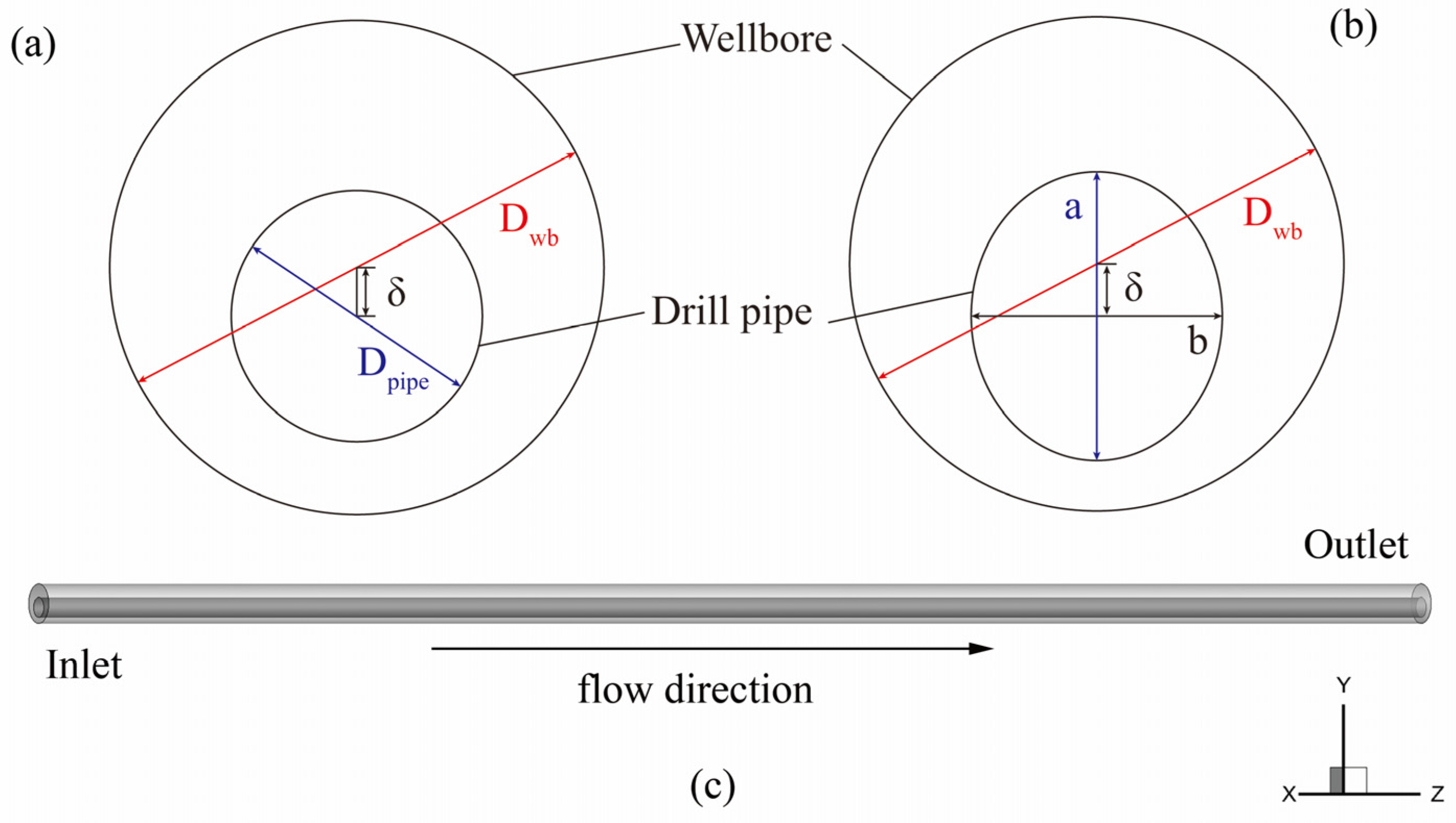
In this work, a three-dimensional simulation was conducted based on the previous experiment [13]. However, the pre-calculations showed that the calculation efficiency was not appropriate for the experimental analysis with a real scale in the present situation, so the annulus length adopted in this model was shortened to L = 2 m when compared with the experimental annulus length of L = 6 m. The main observation parameter of the simulation is the volume concentration of cuttings in a section of annulus length. It is a compromise between ensuring the accuracy of calculation and significantly reducing the computation cost. The annular geometry and the cross-section diagram of the circular drillpipe and elliptical drillpipe are presented in Figure 1. The detailed parameters of the annular space are listed in Table 1.
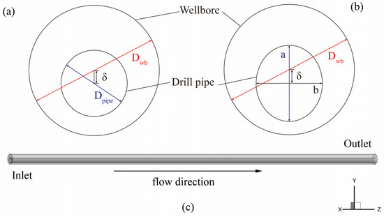
Figure 1.
Physical model of the annulus. (a) cross section of the circular annulus; (b) cross section of the elliptical annulus; (c) detailed view of the annulus.

Table 1.
Geometrical parameters of the annular space.
2.3. Boundary Conditions and Grid Independence Study
The boundary condition is the velocity inlet condition at the entrance of the annulus, and the turbulence intensity at the entrance is also given by:
The pressure outlet condition was adopted for the outlet, and the pressure was set equal to 1 atm. The no-slip condition was imposed on the walls of the wellbore and the drillpipe. The sliding mesh (SM) method was used to carefully deal with the interface between static and moving parts in the flow field. An interface was introduced to exchange all parameters in the liquid and solid governing equations between the static and moving zones. The governing equations of the model are discretized by the finite-volume method. The well-known phase coupled semi-implicit pressure-linked equation (SIMPLE) algorithm was adopted to couple the pressure and velocity fields. The equations of momentum, volume fraction, turbulent kinetic energy, and turbulent dissipation rate were discretized using the QUICK routine scheme, due to its better adaptation to hexahedral meshes. Time integration was done with a second-order implicit scheme. The numerical computation was considered converged when the scaled residuals of different variables are lower than 10−5. The physical parameters of the liquid and solid phases in the simulation are shown in Table 2.
Table 2.
The physical parameters of drill cuttings and drill fluid.
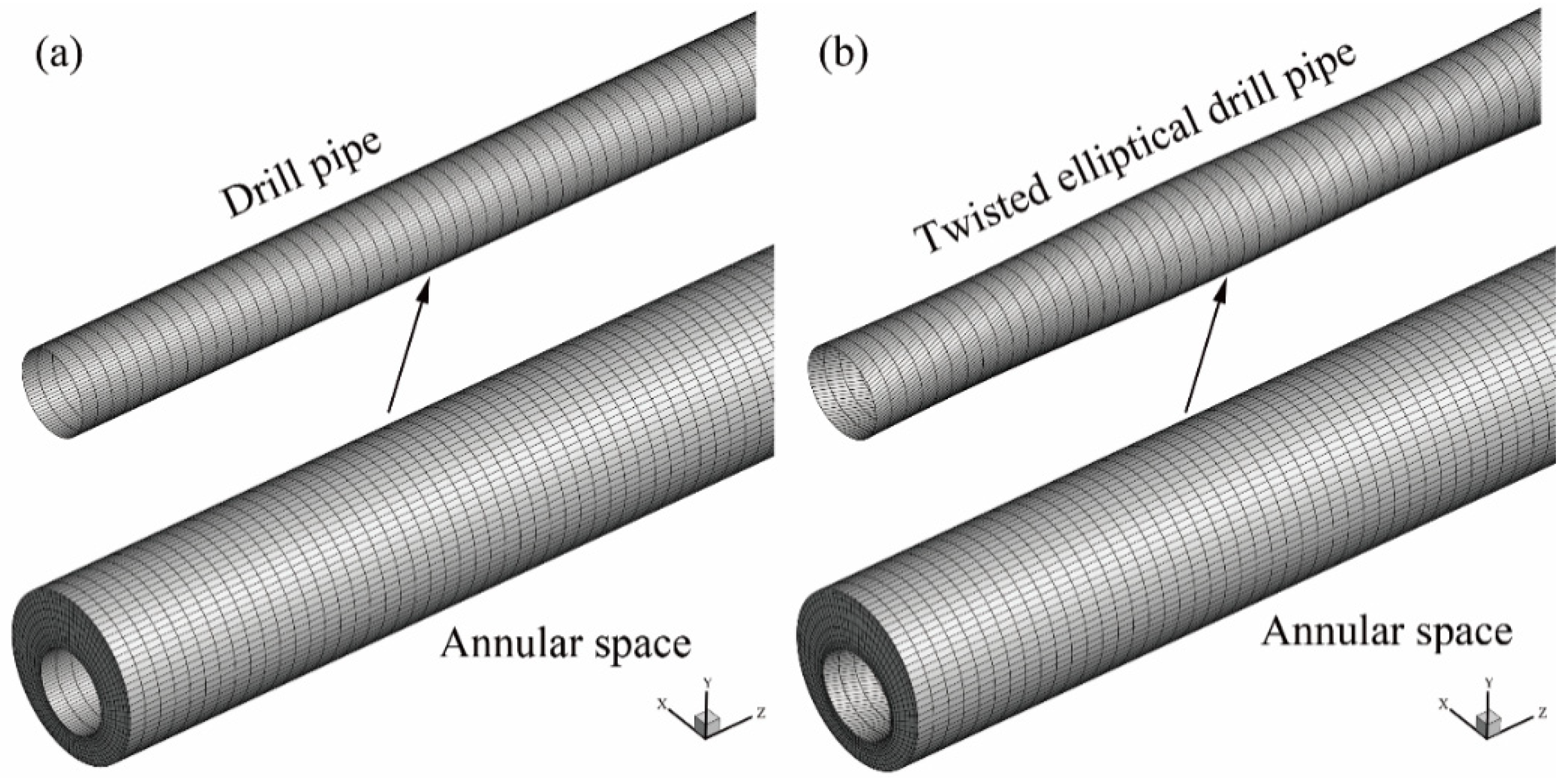
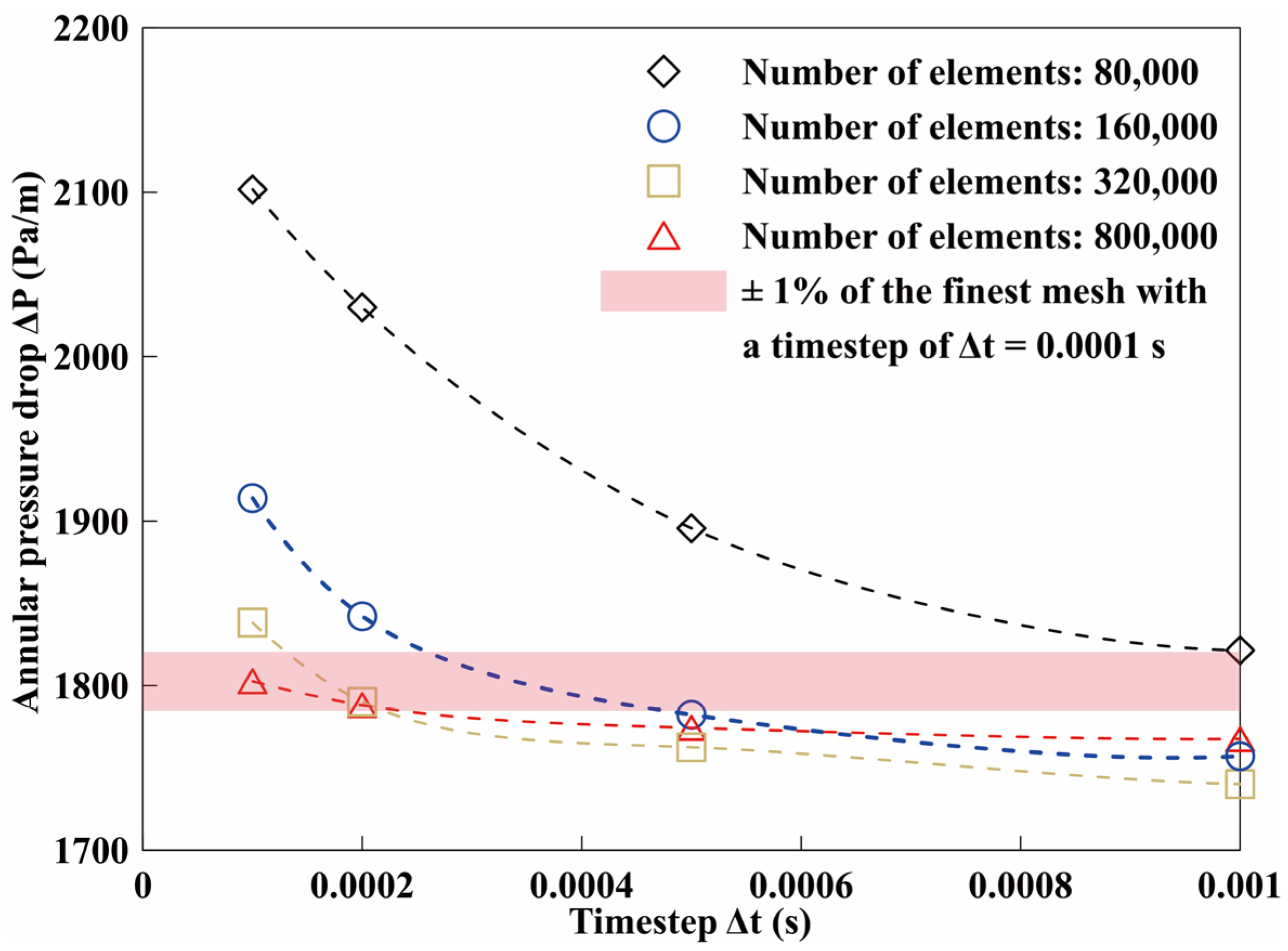
As shown in Figure 2, the hexahedral structured mesh of the cylindrical annulus was adopted for the modeling. The standard wall function approach was used near the wall to ensure the accuracy of the CFD results. To guarantee the accuracy of the numerical results, four meshing schemes with different grid numbers (8.0 × 10⁵, 1.6 × 10⁶, 3.2 × 10⁶, and 8.0 × 10⁶ meshes) were used for grid independence and validation, and the verification results are shown in Figure 3. The maximum difference of annular pressure drop between 3.2 × 10⁶ meshes, when the timestep was Δt = 0.0002 s, and 8.0 × 10⁶ meshes, when the timestep is Δt = 0.0001 s, was less than 1%. Therefore, the elliptical annulus was considered to have a better grid independence with a grid of 3.2 × 10⁶ meshes and Δt = 0.0002 s, and this mesh distribution and the timestep of Δt = 0.0002 s was utilized through the research.
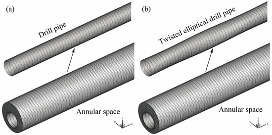
Figure 2.
Detail view of computational mesh (grid number 3.2 × 10⁶). (a) Circular drillpipe. (b) Twisted elliptical drillpipe.

Figure 3.
Grid independence test.
2.4. Verification of CFD-Based Simulation
To verify the reliability of the CFD model and the accuracy of this numerical method, the pre-mentioned CFD model used in this paper was verified. As seen in Figure 4, the simulations were obtained by comparing the annular cuttings concentration of a circular drillpipe between the experimental results [13]. Among the validation, the mean value of the relative error was 8.2%, which indicates that the present CFD-based simulation is reliable for the liquid–solid flow simulation in the annular space.
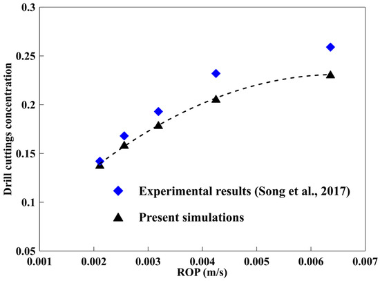
Figure 4.
Comparison between numerical results and experimental results in a horizontal wellbore [13].
3. Results and Discussion
3.1. Effect of Drillpipe Rotation
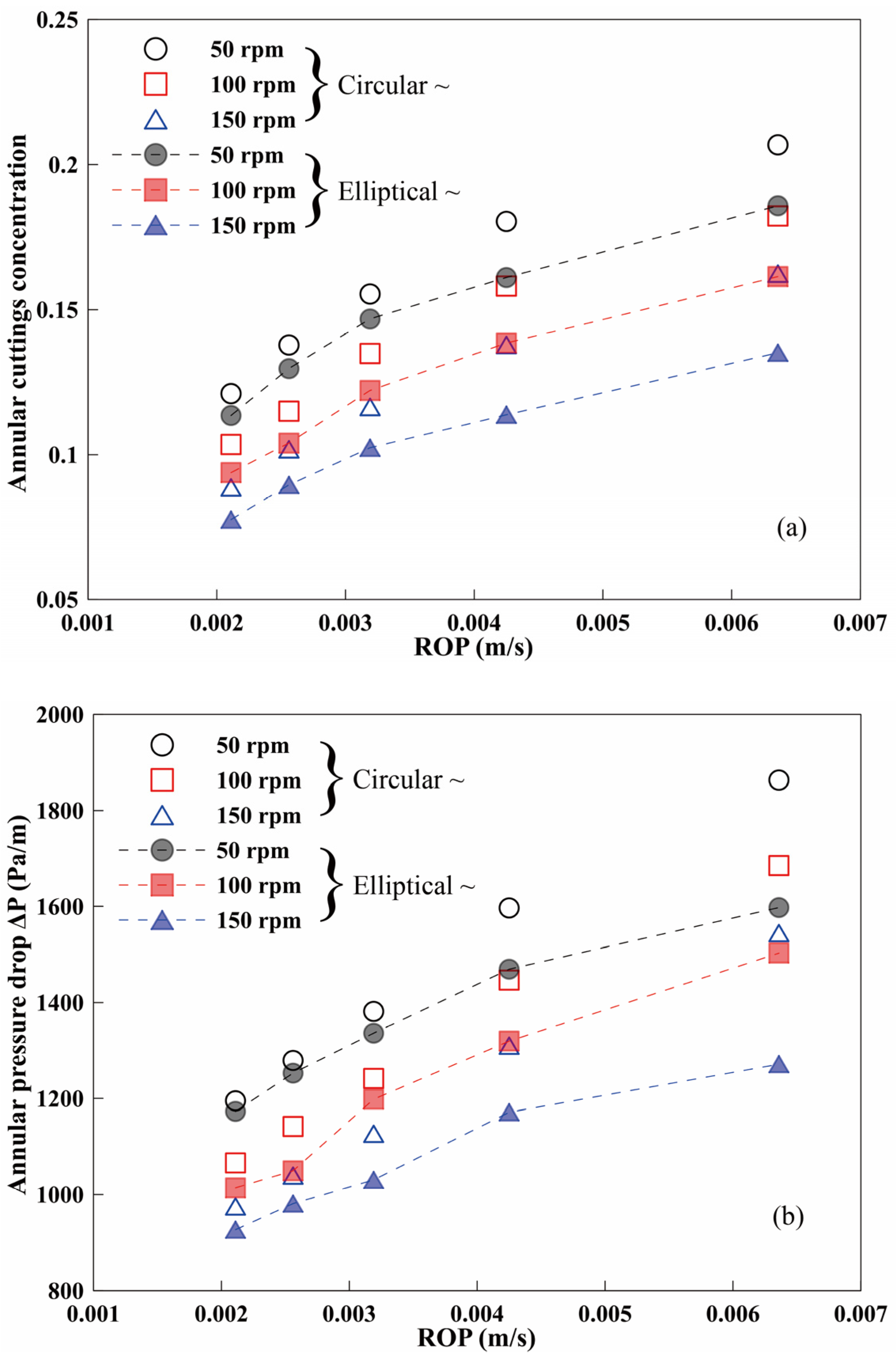
The influences of varying pipe rotational speeds on annular cuttings’ concentration and pressure drops are presented in Figure 5. As seen in Figure 5a, the annular cutting concentration decreases with the increase of rotational speed, due to the centrifugal force and shear force produced by rotating the drillpipe. This is the same as laboratory results of Ozbayoglu et al., 2012 [30]. At the rotational speeds of 50, 100, and 150 rpm, the cuttings’ concentration in the annulus, composed of an elliptical drillpipe, had reduced by 7.7, 11.4, and 14.2% on average when compared with the circular drillpipe. This means that the higher the rotational speed, the better the hole cleaning performance of the elliptical drillpipe, but this improvement degree is no longer significant when the rotational speed is high. As seen in Figure 5b, the change of annular pressure drops almost keep the same trend of change as that of the cuttings’ concentration; the change in the annular pressure drop is more sensitive to a high rotational speed. For example, at the conventional rotational speed of 50, 100, and 150 rpm, the pressure drops in the annulus that was composed of elliptical drillpipe were 5.9, 7.0, and 9.5% lower than those of the circular drillpipe. We infer that the combined effects of the decreased degree of hole cleaning improvement and the rise of the annular pressure drop yields this phenomenon. The velocity fluctuation and the collision between particles and particles/wall, caused by the increase of pipe rotational speed, are more substantial with the elliptical drillpipe, and the annular pressure drop increases.
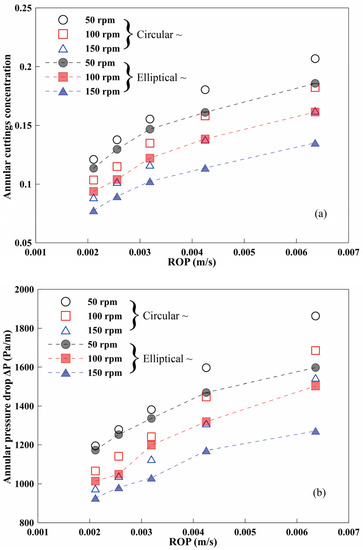
Figure 5.
Annular cuttings’ concentration and pressure drop with different rotational speeds. (a/b = 1.1 for elliptical drillpipe; e = 0.4). (a) Annular cuttings’ concentration. (b) Annular pressure drop.
In order to evaluate the hole cleaning efficiency of the elliptical drillpipe, compared with the circular drillpipe, the variation of the degree of hole cleaning improvement with different rotational speeds is shown in Figure 6. The hole cleaning ability of the elliptical drillpipe gradually improved as the rotational speed increased. The hole cleaning effect is more apparent when the value of ROP is high. For example, when the rotational speed was 50 rpm, in the ranges of ROP used in the simulation, the hole cleaning effect of the elliptical drillpipe with minimum ROP and maximum ROP increased by 6.2 and 10.2%, respectively. Although the ROP is an index to evaluate drill bit performance, poor hole cleaning in the annulus caused by the high value of ROP is also a problem that needs full attention. It can be observed that at the rotational speed of 50, 100, and 150 rpm, the hole cleaning effect of the elliptical drillpipe at ROP = 0.00636 m/s reached 10.2, 11.8, and 16.8%, respectively. It explains the fact that when the value of ROP is considerable, maintaining the elliptical drillpipe at a higher rotational speed will have a better hole cleaning performance.
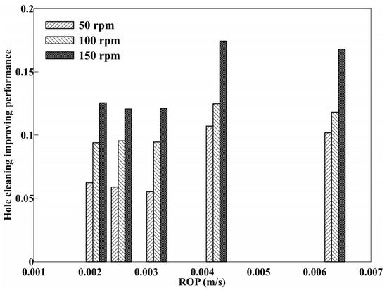
Figure 6.
Hole cleaning efficiency of the elliptical drillpipe. (a/b = 1.1 for elliptical drillpipe; e = 0.4).
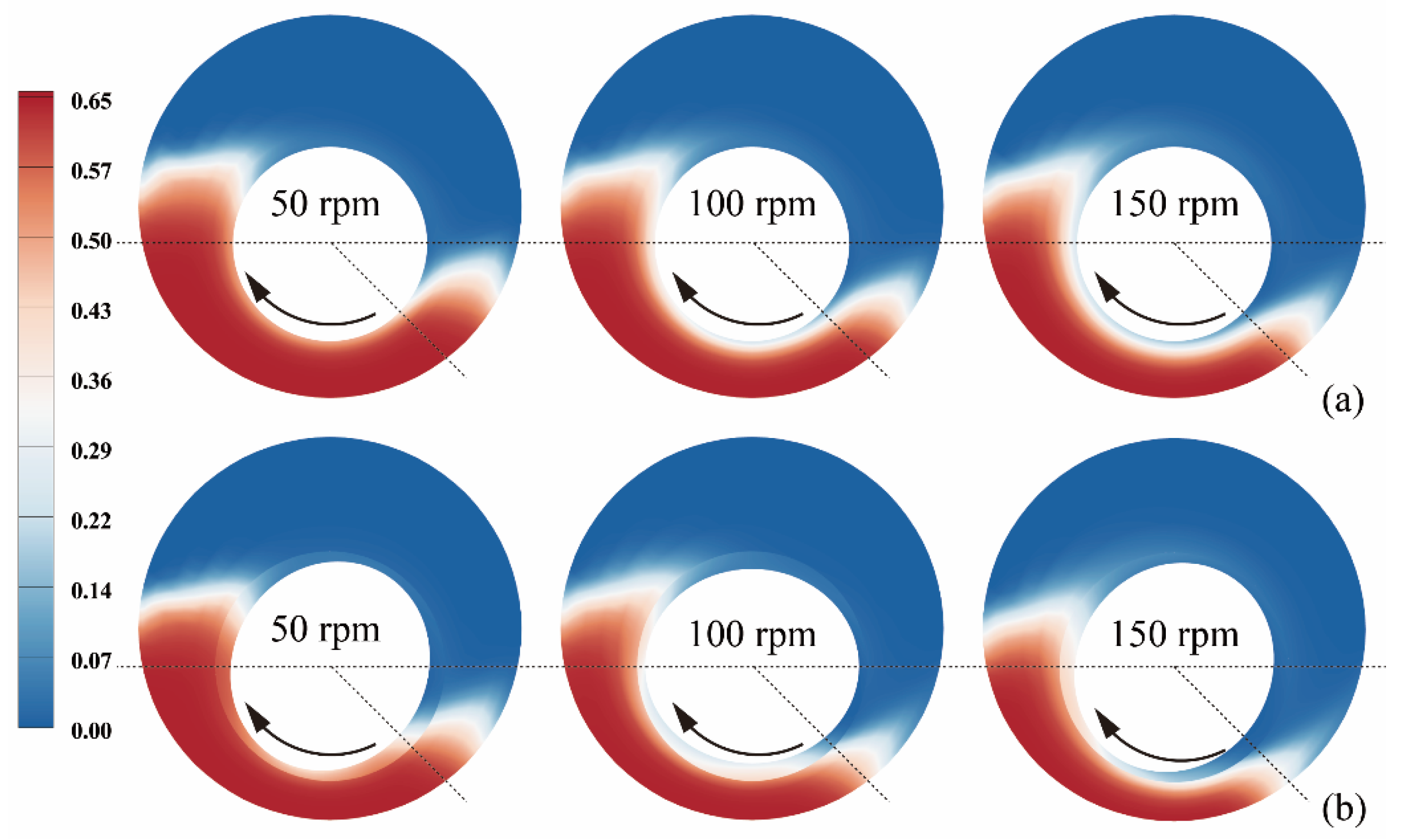
Figure 7 shows the cross-section of the cuttings’ distribution in the annulus composed of the circular drillpipe and elliptical drillpipe under different rotational speeds. Similar to the experimental reports, the profile of the cuttings’ bed presents the swaying phenomenon due to drillpipe rotation [14]. The swaying phenomenon is obvious due to higher drag forces applied to cuttings under the action of elliptical drillpipe rotation [31]. The cuttings bed distribution on the low side of the annulus is deflected towards the direction of drillpipe rotation. The cuttings bed on the high-side of the annulus reaches a dynamic equilibrium state under the combined action of axial high-speed fluid and the secondary flow caused by the elliptical drillpipe [22]. The high-side cuttings bed does not change obviously with the change of rotational speed, but the deflecting effect of the cuttings bed on the low-side is noticeable. Due to the friction and shear forces exerted by the rotating elliptical drillpipe, the tendency of cuttings particles to move in the direction of the rotation of the drillpipe is more significant, which is equivalent to reducing the number of cutting particles in the cuttings’ bed and improving the hole cleaning efficiency.

Figure 7.
Contours of cuttings’ concentration with different rotational speeds. (a) circular drillpipe (a/b = 1.0). (b) elliptical drillpipe (a/b = 1.1, non-twisted). (ROP = 0.00636 m/s, e = 0.4).
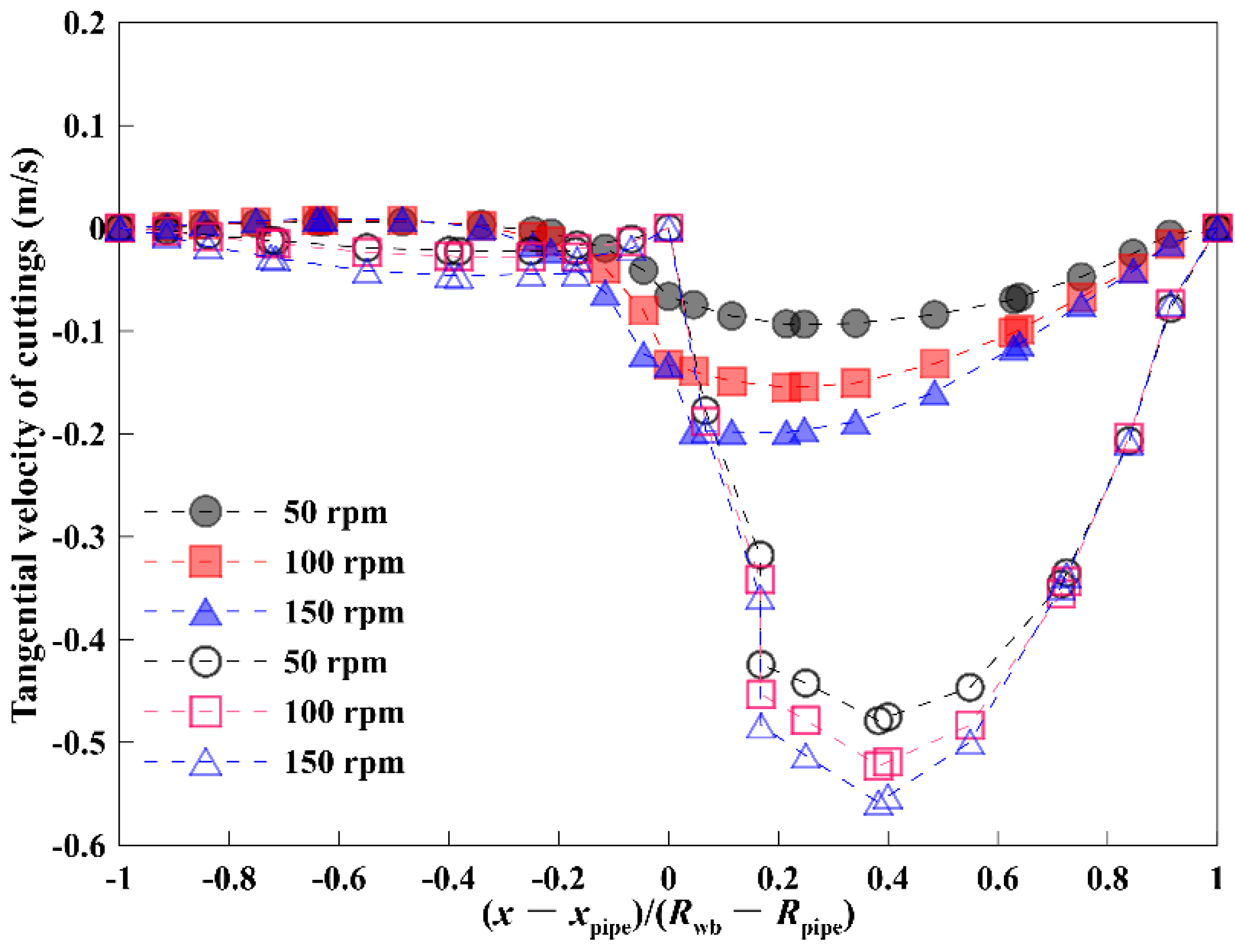
The shear force generated by rotating the drillpipe is equivalent to exerting tangential kinetic energy on the drilling fluid. As the carrier for cuttings, the change of tangential kinetic energy of drilling fluid will inevitably cause the tangential velocity of drill cuttings to change. Figure 8 depicts the tangential velocity distribution of drill cuttings along the radial direction. Rotating the drillpipe enables the cuttings to obtain a higher tangential kinetic energy from the drilling fluid, increasing the tangential velocity and improving transport efficiency. The cuttings’ tangential velocity distribution decreases to the minimum at the wall and reaches the maximum at the core area inside the annular space. The tangential velocity of the cuttings increases as the rotational speed increases, and the change of tangential velocity caused by the elliptical drillpipe is more prominent. For example, when different rotational speeds were selected (50, 100, and 150 rpm), the maximum tangential velocity of cuttings under the action of the elliptical drillpipe increased by 412.5, 237.7, and 181.4%, respectively when compared with that of circular drillpipe. It indicates that the rotation of the elliptical drillpipe has a strong tangential disturbance effect on the drilling fluid, thus increasing the tangential velocity of the drill cuttings.
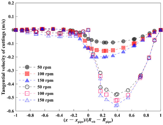
Figure 8.
Tangential velocity of cuttings under different rotational speeds. (ROP = 0.00636 m/s, e = 0.4).
3.2. Effect of Major to Minor Axial Ratio a/b
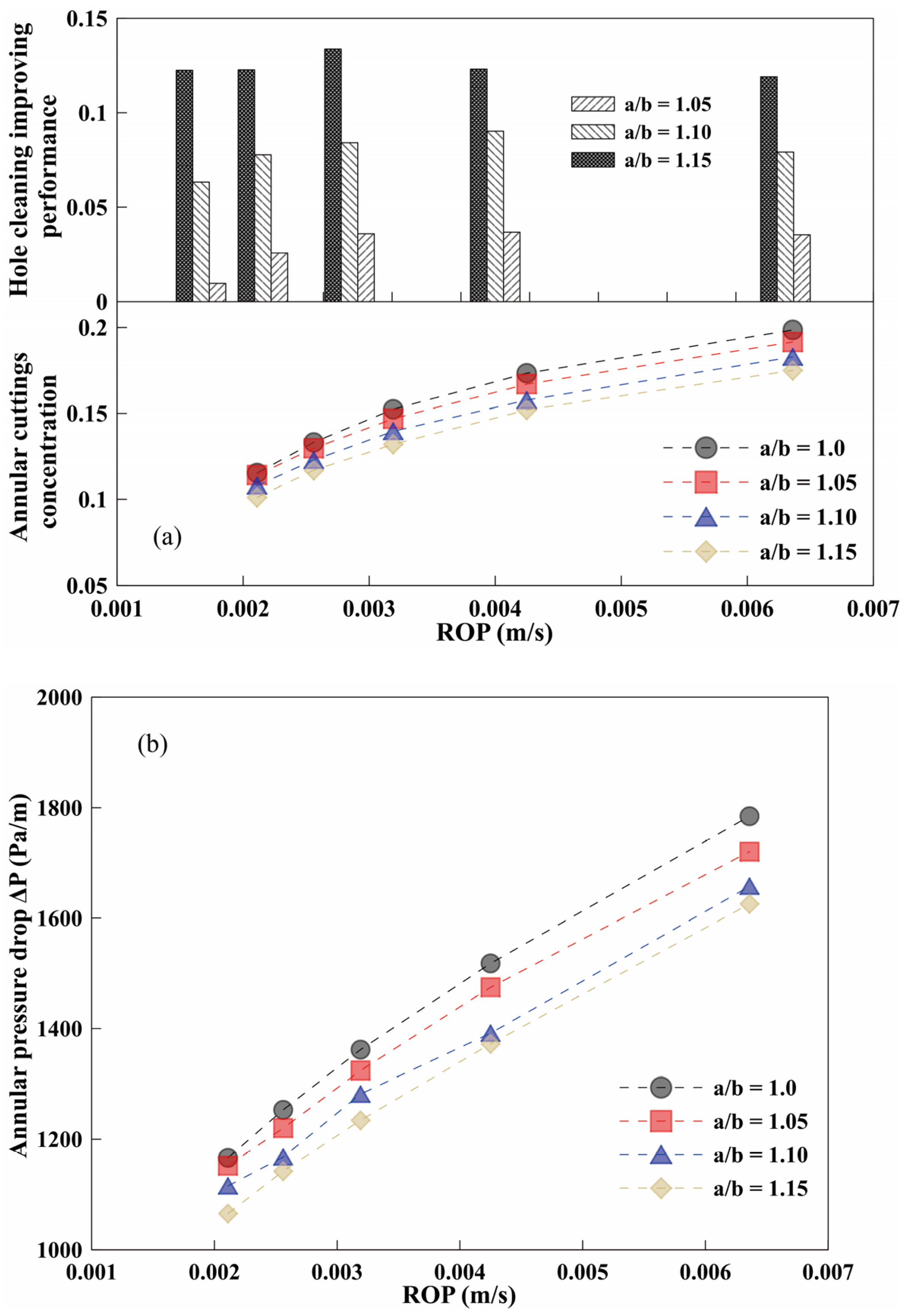
The variation of the annular cuttings’ concentration and annular pressure drop with the major to minor axial ratio is indicated in Figure 9. As shown in Figure 9a, the annular cuttings’ concentration increases with the decrease of the axial ratio and the increase of ROP. At different ROPs, the cuttings concentration in the annulus composed of four types of elliptical drillpipe (a/b = 1.0, 1.05, 1.10, and 1.15) was 15.5, 15.0, 14.2, and 13.5% on average, respectively. When compared with the circular drillpipe, a degree of hole cleaning improvement in the elliptical drillpipe was obtained. When a/b = 1.05, 1.10, and 1.15, the cuttings removal efficiency was 3.2, 8.4, and 13.0%, respectively. The best hole cleaning effect was obtained when the axis ratio was large. As shown in Figure 9b, the annular pressure drop increases almost linearly with the decrease of the axis ratio and the increase of ROP. The height of the cuttings’ bed had reduced, which increased the area of the annular flow channel, thereby reducing the annular pressure drop. Although the rise of axis ratio will also cause the increase in annular pressure drop, the effect of pressure drop reduction caused by the removal of the cuttings’ bed is more significant. It is a good choice to increase the axial ratio when conditions permit, especially in areas with an obvious cuttings’ deposition.
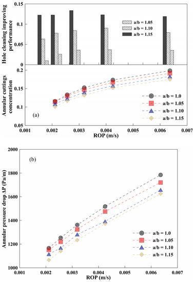
Figure 9.
Annular cuttings’ concentration and pressure drop with different axial ratios. (100 rpm; e = 0.2). (a) Annular cuttings’ concentration. (b) Annular pressure drop.
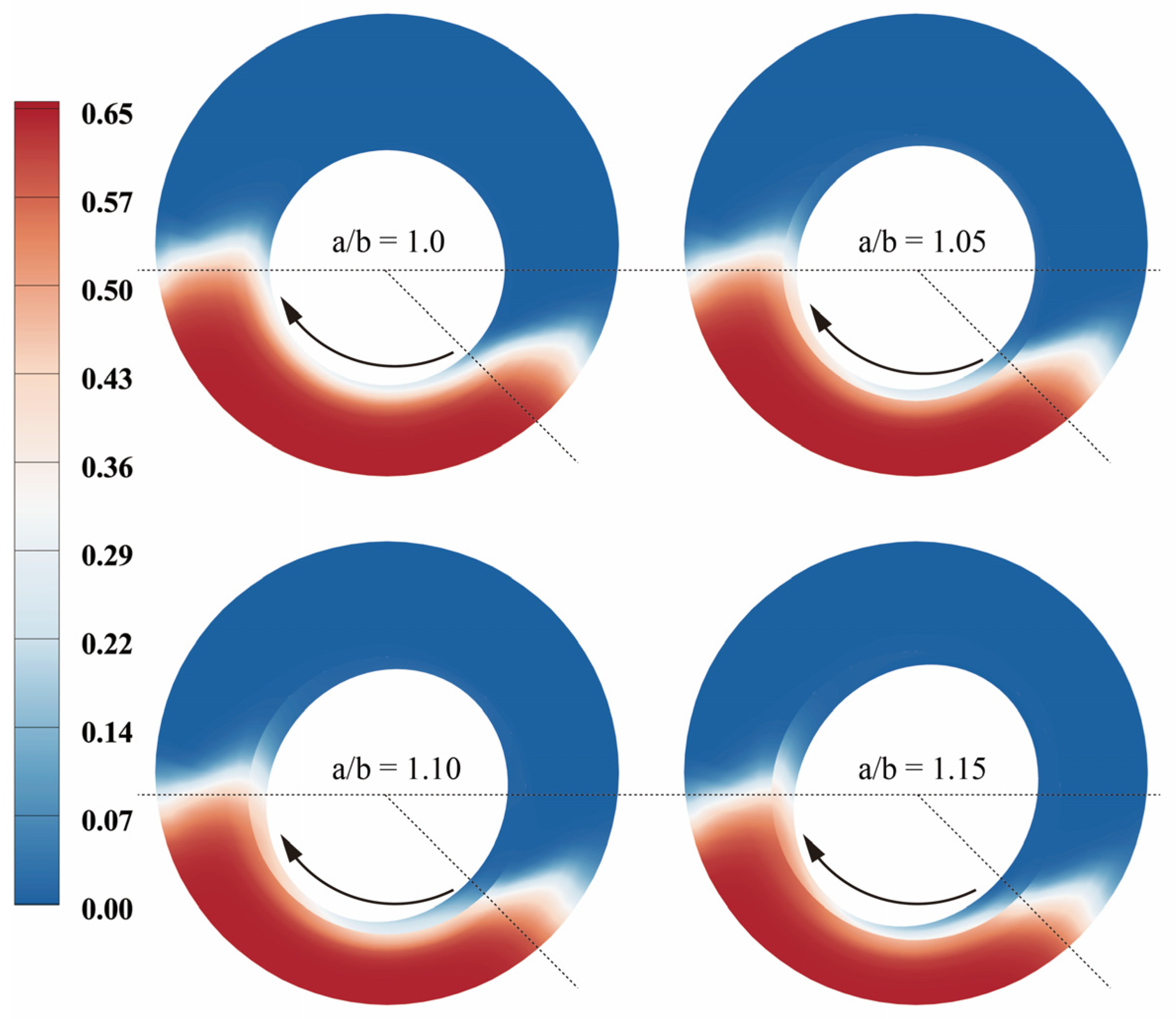
The contours of the annular cuttings’ concentration under different axial ratios are shown in Figure 10. It is observed that the cuttings concentration decreases slightly with the increase of the axis ratio, which indicates that the ability to promote cuttings’ transportation was slightly enhanced. The interval of the flow channel at the low side of the annulus will periodically change with the pipe rotation. As the major axis of the elliptical drillpipe touched the cuttings’ bed, pipe rotation continuously shook cuttings out of their bed into the moving stream above the bed, promoting the cuttings’ bed erosion significantly [14]. The cuttings on the high side of the cuttings bed increased the transport ability due to the increase of the tangential momentum, which makes it possible to reach the minimum transport velocity (MTV) of cuttings’ transportation. The cuttings’ particles entered the main flow area of drilling fluid of the wide gap and left the annulus with the flow of drilling fluid.

Figure 10.
Contours of cuttings’ concentration with different axial ratios. (100 rpm, ROP = 0.00425 m/s, e = 0.2).
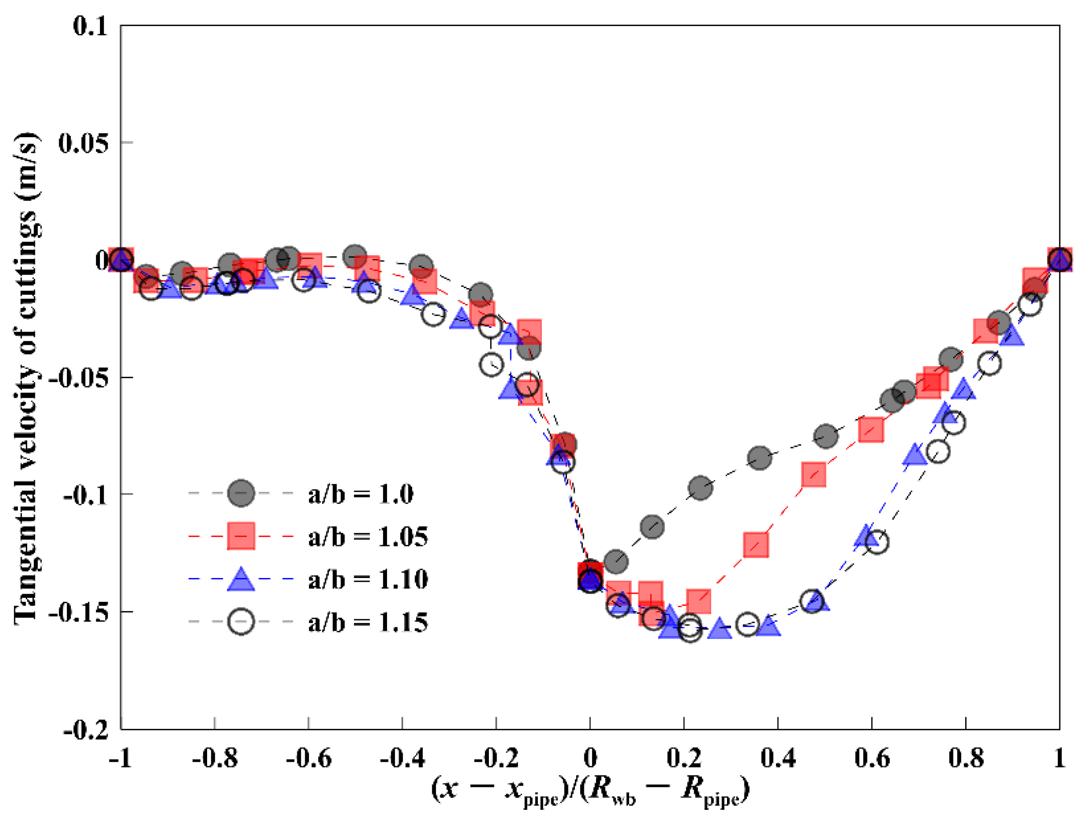
Figure 11 represents the change of cuttings’ tangential velocity with different axial ratios. The tangential velocity of cuttings at the pipe wall surface reaches its maximum, and then decays rapidly along the radial direction when the drillpipe is circular. In the case of an elliptical drillpipe, the tangential velocity distribution of the cuttings reached its peak inside of the annulus. This is due to the secondary flow phenomenon induced by the irregular shape of the ellipse, which increases the tangential kinetic energy intensity and the continuous range of the drilling fluid. When compared with the circular drillpipe with a/b = 1.0, the maximum tangential velocity of drill cuttings increases by 19.0% when the axial ratio is a/b = 1.15.
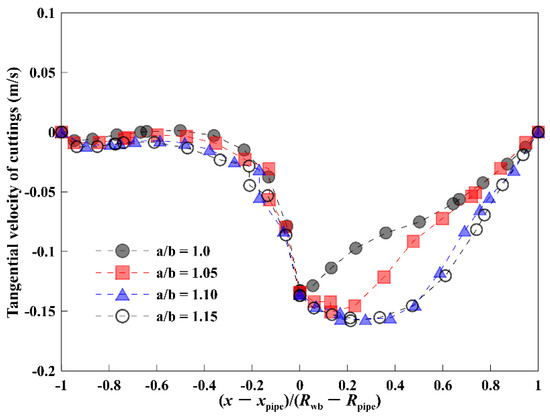
Figure 11.
Tangential velocity of cuttings under different axis ratios. (ROP = 0.00425 m/s, e = 0.2).
3.3. Effect of Eccentricity
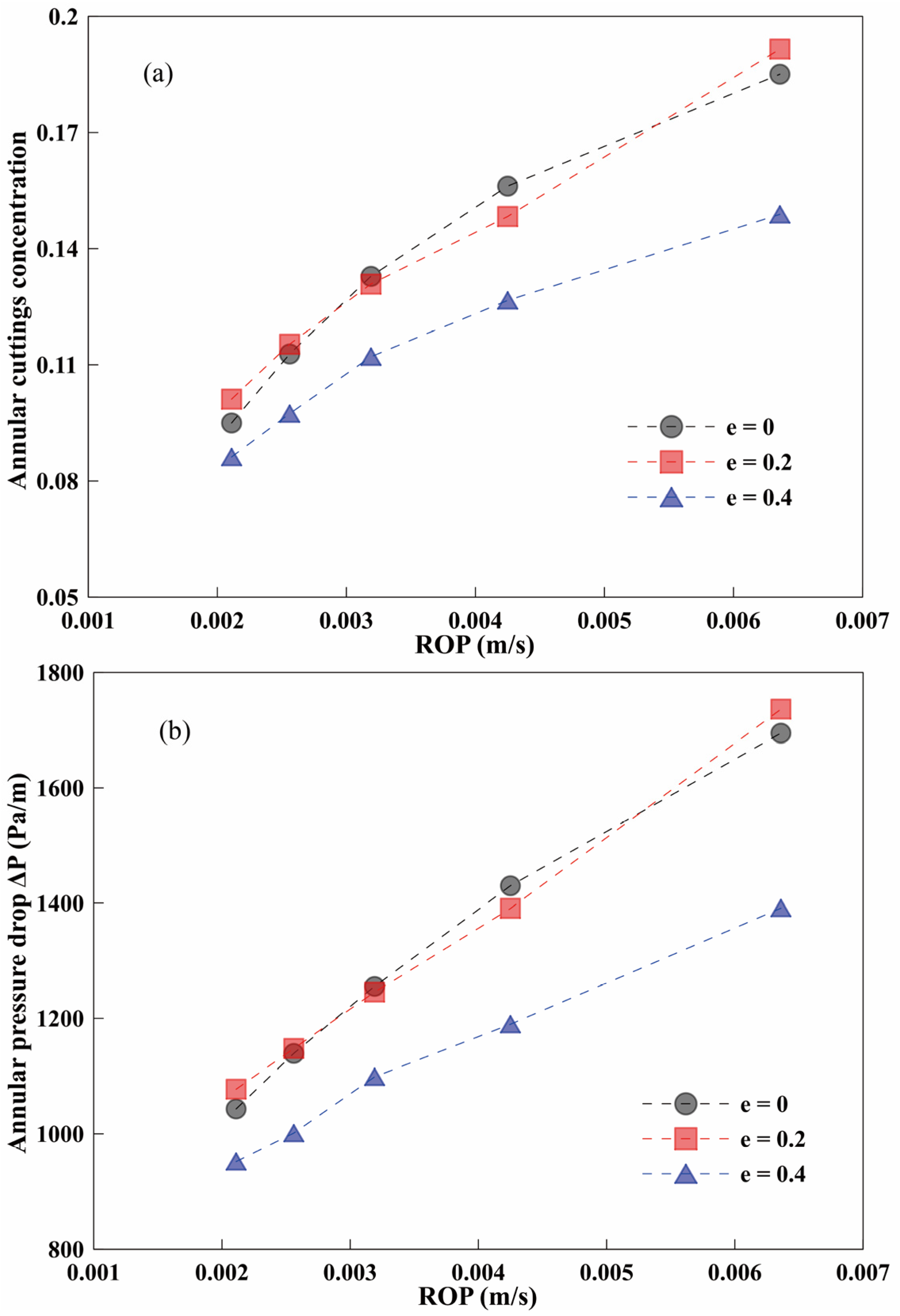
In the actual drilling process, the drillpipe eccentricity is a common issue due to gravity. Figure 12 illustrates the variations of annular cuttings’ concentration in the elliptical drillpipe under different eccentricities. According to the numerical results, drillpipe eccentricity can increase the cuttings’ accumulation [6]. As seen in Figure 12a, the annular cuttings concentration with the eccentricity of e = 0 and e = 0.2 is almost the same. In contrast, the annular cuttings concentration with the eccentricity of e = 0.4 is significantly reduced. It indicates that the hole cleaning performance of the elliptical drillpipe had gradually improved with the increase of eccentricity. The rise of eccentricity is more conducive to promoting the suspension of cuttings particles and improving transport efficiency. It can be seen from Figure 12b that the change in annular pressure drop is consistent with the change in the annular cuttings concentration. Unlike the circular drillpipe, the elliptical drillpipe will have a better hole cleaning effect when the eccentricity is large. So, the height of the bed, and the annular pressure drop are close at e = 0 and e = 0.2. A smaller annular pressure drop will be obtained when the eccentricity is further increased to e = 0.4, due to its strong ability to promote cuttings’ transport.
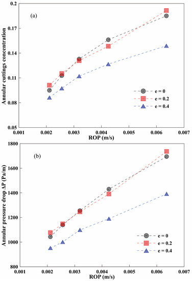
Figure 12.
Annular cuttings’ concentration and pressure drop with different eccentricities. (a/b = 1.05, 150 rpm). (a) Annular cuttings’ concentration. (b) Annular pressure drop.
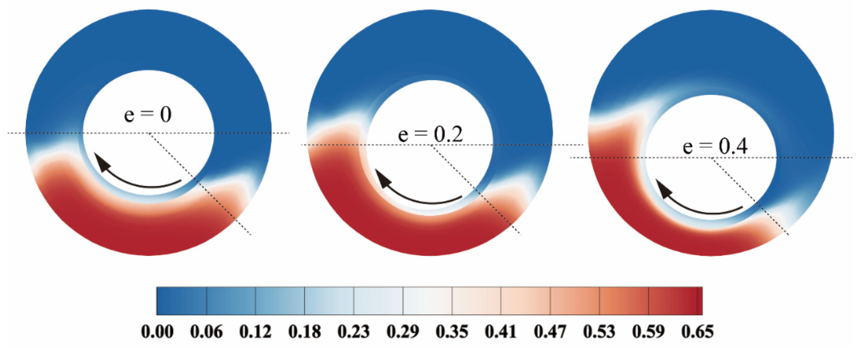
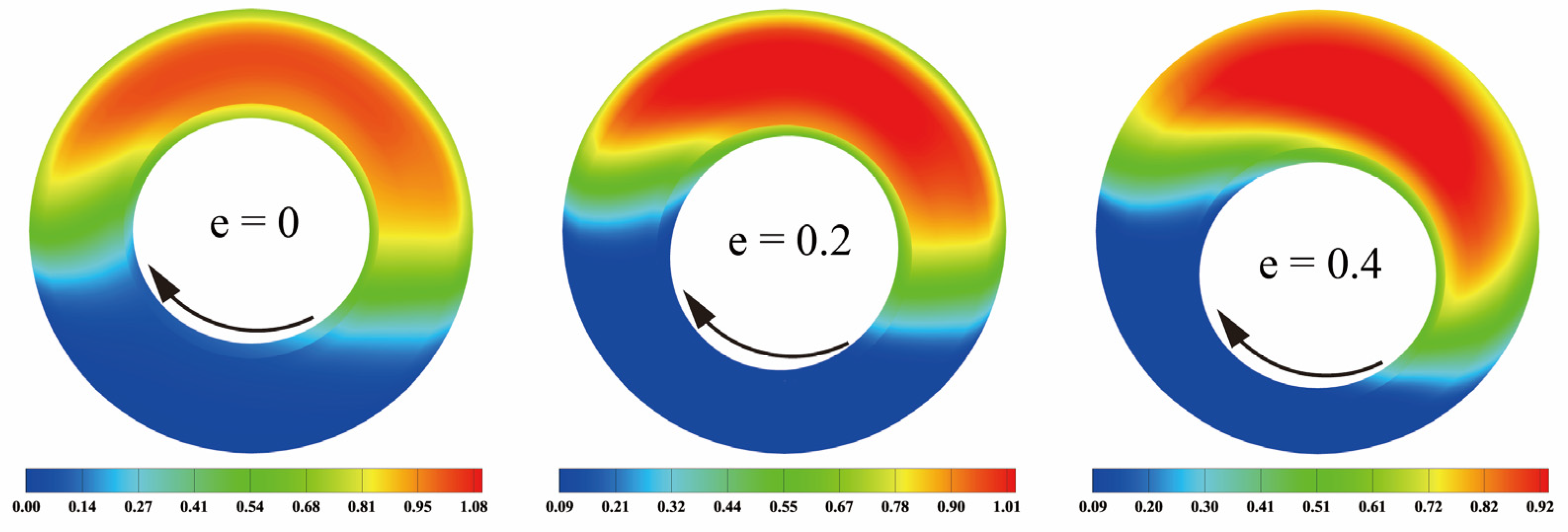
Figure 13 shows the distribution of annular cuttings’ concentration under different eccentricities conditions. With the increase of the eccentricity, the height of the cuttings’ bed decreases, but the circumferential distribution range of the cuttings bed becomes larger [6]. This performance is due to the cuttings’ bed offset caused by the rotating elliptical drillpipe. When the eccentricity becomes larger, the offset effect becomes more and more apparent, and it will cause the particles at the low part of the bed to deflect towards the rotation direction. The particles at the high part of the bed will be more easily suspended in the drilling fluid and move out of the wellbore as the drilling fluid flows.
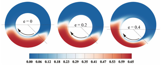
Figure 13.
Contours of cuttings’ concentration with different eccentricities. (150 rpm, a/b = 1.05, ROP = 0.00636 m/s).
Figure 14 shows the contour plots of the axial velocity distribution of drilling fluid in the annulus with different eccentricities conditions. It can be observed that the core area of axial velocity also deflects in consistency with the direction of the drillpipe rotation, and the larger the eccentricity is, the more obvious the effect of deflection is. With the increase of eccentricity, the effect of the elliptical drillpipe rotation on the distribution of the cuttings’ bed, and the axial velocity of drilling fluid at wide gap is more obvious. The axial velocity of the drilling fluid in the core area decreased with the increase of the eccentricity, confirming that the area of the cuttings’ bed decreased with the rise of eccentricity. It indicates that the reduction of the area of the cuttings’ bed is equivalent to the increase of the fluid flow area in the annulus. At the same flow rate, the axial velocity of drilling fluid in the wide gap of the annulus decreases.

Figure 14.
Contours of axial velocity of drilling fluid with different eccentricities. (150 rpm, a/b = 1.05, ROP = 0.00636 m/s).
3.4. Effect of Pitch Length Ratio (P/Dpipe)
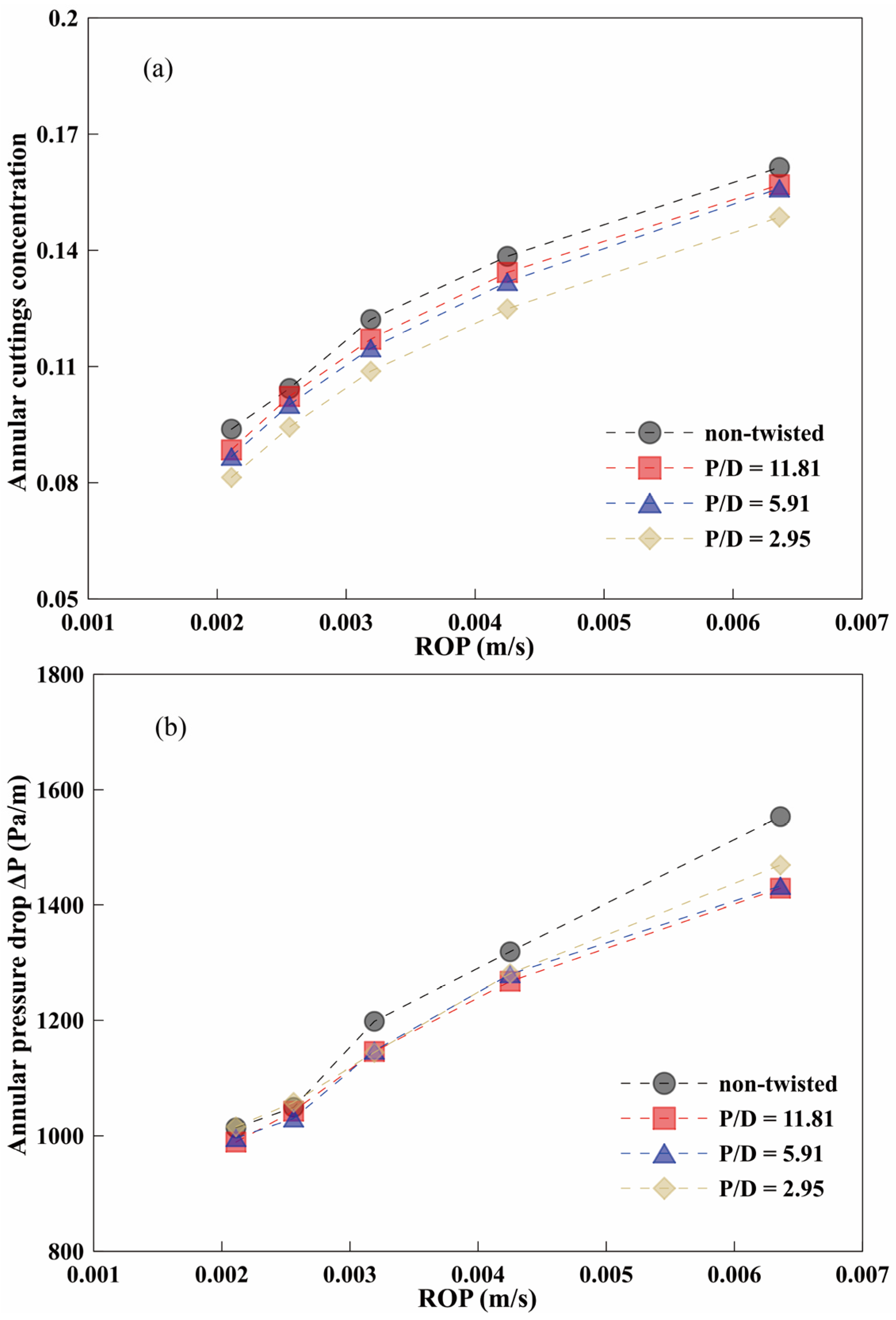
From some of the fields of industrial engineering, the application of a twisted elliptical tube may play a more active role [24,32]. The twisted elliptical tube can generate swirl flow or secondary flow, disturbing the boundary layer periodically and enhancing the heat transfer capacity. Therefore, the annular cuttings concentration and pressure drop of the elliptical drillpipe with different pitch length ratios are shown in Figure 15. The pitch length P is defined as the pipe length that undergoes 360° rotation; a smaller pitch length ratio means a more pronounced distortion of the pipe wall. As seen in Figure 15a, the hole cleaning ability of the elliptical drillpipe increased with the decrease in the pitch length ratio. The hole cleaning performance of the twist elliptical drillpipe was the strongest at pitch length ratio to pipe diameter (P/D) = 2.95. This can be attributed to the more vigorous fluid mixing caused by the intense twist degree of the pipe wall when the pitch length ratio is small. The decrease of pitch length ratio can promote cuttings’ transport, but at the same time, will inevitably cause additional pressure loss. As seen in Figure 15b, the annular pressure drop under different ROPs did not change significantly with the increase of pitch length ratio. This can be explained by the fact that equilibrium is formed between the reduction of annular pressure drop caused by hole cleaning improvement, and the increase of pressure drop caused by twist geometry.
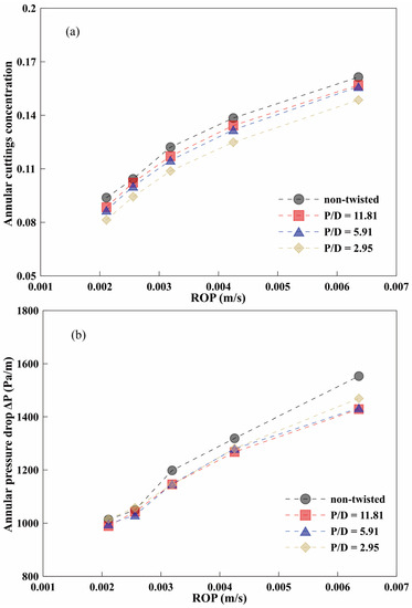
Figure 15.
Annular cuttings concentration and pressure drop with different pitch length ratios. (a/b = 1.1, 100 rpm, e = 0.4). (a) Annular cuttings’ concentration. (b) Annular pressure drop.
Figure 16 shows the turbulent kinetic energy (TKE) distribution under different pitch length ratios. The TKE can indicate the degree of turbulence in the flow caused by the rotation of the elliptical drillpipe. A higher value of TKE represents a minimal slip velocity and a higher cutting transport efficiency [21]. It can be regarded as an important parameter for cuttings particles that transport from the annulus. It can be observed that in the radial direction, the TKE obtained its maximum value inside of the annular space. With the increase of the pitch length ratio, the TKE value of the fluid in the annulus tends to increase. When P/D = 2.95, the maximum TKE value increased by 24.5% when compared with the circular drillpipe. The area with a higher value of the TKE represents the minimal slip velocity thereon, so the possibility of clustering of the cuttings in the form of the bed at the bottom could be avoided [33].
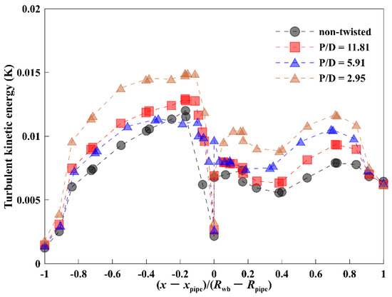
Figure 16.
TKE distribution under different pitch length ratios. (a/b = 1.1, 100 rpm, e = 0.4, ROP = 0.00636 m/s).
In order to better understand the influence of the wall rotation of the elliptical drillpipe on the turbulence effect of the surrounding fluid. Figure 17 illustrates the contours of the TKE under different pitch length ratios. According to this Figure, by decreasing the pitch length ratio, TKE increases inside the annulus, resulting in a better hole cleaning effect [21]. The hole cleaning enhancement mechanisms using the elliptical drillpipe can be explained as (1) the swirl flow mixing between the core zone and the near-wall zone increases the kinetic energy of the drilling fluid; (2) the turbulent intensity is increased in the near rotating-wall zone. When the pitch length ratio is significant, the eddy current scale in the annulus is large, so the turbulence intensity is large, promoting the cuttings’ transport and improving the hole cleaning efficiency.
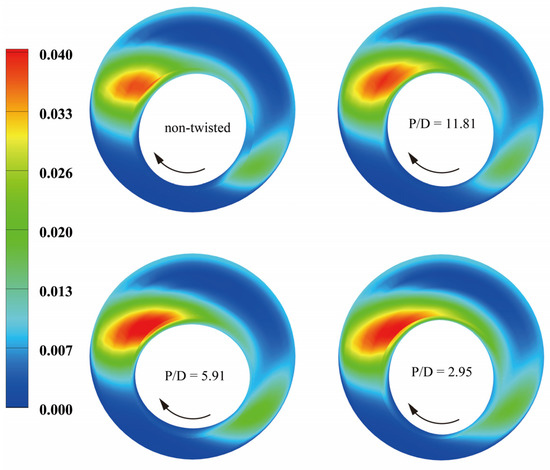
Figure 17.
TKE distribution under different pitch length ratios. (a/b = 1.1, 100 rpm, e = 0.4, ROP = 0.00636 m/s).
4. Conclusions
In this study, the Eulerian-Eulerian approach was used to model and simulate the cuttings transport behavior in the annulus composed of the elliptical drillpipe. The results have been compared with the experimental data, and the accuracy and validity of the modeling and the computations were examined. Analysis of the solid–liquid flow was carried out in order to determine the effect of drillpipe rotation, ROP, eccentricity, axial ratio, and pitch length ratio on the pressure drop and cuttings’ concentration. The hole cleaning ability of the elliptical drillpipe and the circular drillpipe was compared and evaluated.
The rotational speed played an essential role in improving the hole cleaning ability of the elliptical drillpipe. When the rotational speed becomes greater, the cuttings’ transport ability can be effectively improved. At a higher ROP, high rotational speed will have a better hole cleaning performance. The increase of the major to minor axis ratio will also cause an increase of annular pressure drop and the decrease of annular cuttings’ concentration. The larger the axial ratio of the elliptical drillpipe, the stronger the improving effect of hole cleaning. Due to the change of the relative position of the drillpipe and cuttings bed, unlike the circular drillpipe, the hole cleaning performance of the elliptical drillpipe gradually improved with the increase of eccentricity. The hole cleaning ability of the elliptical drillpipe increased with the decrease of the pitch length ratio. However, at the same time, it will inevitably cause additional pressure loss.
Therefore, the developed computational model has successfully captured the key features of cuttings’ transport behavior in the annulus via an elliptical drillpipe. The model and results presented in this paper are helpful to extend the application of the CFD model for simulating the annular solid–liquid two-phase flow phenomenon with different kinds of devices used for hole cleaning. The present work makes a useful contribution to understanding the complex flow processes caused by the rotating elliptical drillpipe.
Author Contributions
Conceptualization, G.J.; methodology, T.Y.; validation, X.S.; writing—original draft preparation, G.J.; writing—review and editing, G.J. All authors have read and agreed to the published version of the manuscript.
Funding
This research was funded by the National Natural Science Foundation of China (grant number 51674087) and the National Science and Technology Major Project of the Ministry of Science and Technology of China (grant number 2017ZX05009-003).
Conflicts of Interest
The authors declare no conflict of interest.
References
- Zhang, W.; Xie, P.; Li, Y.; Teng, L.; Zhu, J. Hydrodynamic characteristics and mass transfer performance of rotating packed bed for CO2 removal by chemical absorption: A review. J. Nat. Gas Sci. Eng. 2020, 79, 103373. [Google Scholar] [CrossRef]
- Zhang, J.; Li, Y.; Pan, Y.; Wang, X.; Yan, M.; Shi, X.; Zhou, X.; Li, H. Experiments and analysis on the influence of multiple closed cemented natural fractures on hydraulic fracture propagation in a tight sandstone reservoir. Eng. Geol. 2021, 281, 105981. [Google Scholar] [CrossRef]
- Mahmoud, H.; Hamza, A.; Nasser, M.S.; Hussein, I.A.; Ahmed, R.; Karami, H. Hole cleaning and drilling fluid sweeps in horizontal and deviated wells: Comprehensive review. J. Pet. Sci. Eng. 2020, 186, 106748. [Google Scholar] [CrossRef]
- Guan, Z.C.; Liu, Y.M.; Liu, Y.M.; Xu, Y.Q. Hole cleaning optimization of horizontal wells with the multi-dimensional ant colony algorithm. J. Nat. Gas Sci. Eng. 2016, 28, 347–355. [Google Scholar] [CrossRef]
- Guo, J.; Zhang, L.; Zhu, Q. A quadruple-porosity model for transient production analysis of multiple-fractured horizontal wells in shale gas reservoirs. Environ. Earth Sci. 2015, 73, 5917–5931. [Google Scholar] [CrossRef]
- Heydari, O.; Sahraei, E.; Skalle, P. Investigating the impact of drillpipe’s rotation and eccentricity on cuttings transport phenomenon in various horizontal annuluses using computational fluid dynamics (CFD). J. Pet. Sci. Eng. 2017, 156, 801–813. [Google Scholar] [CrossRef]
- Movahedi, H.; Vasheghani Farahani, M.; Jamshidi, S. Application of Hydrated Basil Seeds (HBS) as the herbal fiber on hole cleaning and filtration control. J. Pet. Sci. Eng. 2017, 152, 212–228. [Google Scholar] [CrossRef]
- Van Puymbroeck, L.; El Bachiri, K.; Williams, H. New generation drill pipe to increase drilling performance in ERD wells. In Proceedings of the SPE/IADC Middle East Drilling Technology Conference & Exhibition, Dubai, United Arab Emirates, 7–9 October 2013; pp. 7–9. [Google Scholar]
- Duan, M.; Miska, S.Z.; Yu, M.; Takach, N.E.; Zettner, R.M.A.C.M. Critical Conditions for Effective Sand-Sized Solids Transport in Horizontal and High-Angle Wells. SPE Drill. Complet. 2009, 24, 229–238. [Google Scholar] [CrossRef]
- Han, S.M.; Woo, N.S.; Hwang, Y.K. Solid-liquid mixture flow through a slim hole annulus with rotating inner cylinder. J. Mech. Sci. Technol. 2009, 23, 569–577. [Google Scholar] [CrossRef]
- Ulker, E.; Sorgun, M. Comparison of computational intelligence models for cuttings transport in horizontal and deviated wells. J. Pet. Sci. Eng. 2016, 146, 832–837. [Google Scholar] [CrossRef]
- Epelle, E.I.; Gerogiorgis, D.I. CFD modelling and simulation of drill cuttings transport efficiency in annular bends: Effect of particle sphericity. J. Pet. Sci. Eng. 2018, 170, 992–1004. [Google Scholar] [CrossRef] [Green Version]
- Song, X.; Xu, Z.; Wang, M.; Li, G.; Shah, S.N.; Pang, Z. Experimental Study on the Wellbore-Cleaning Efficiency of Microhole-Horizontal-Well Drilling. SPE J. 2017, 22, 1189–1200. [Google Scholar] [CrossRef]
- Tomren, P.H. Experiment study of cuttings transport in Directional Wells. SPE Drill. Eng. 1986, 1, 43–56. [Google Scholar] [CrossRef]
- Epelle, E.I.; Gerogiorgis, D.I. A review of technological advances and open challenges for oil and gas drilling systems engineering. AIChE J. 2020, 66. [Google Scholar] [CrossRef]
- Yan, T.; Wang, K.; Sun, X.; Luan, S.; Shao, S. State-of-the-art cuttings transport with aerated liquid and foam in complex structure wells. Renew. Sustain. Energy Rev. 2014, 37, 560–568. [Google Scholar] [CrossRef]
- Boyou, N.V.; Ismail, I.; Wan Sulaiman, W.R.; Sharifi Haddad, A.; Husein, N.; Hui, H.T.; Nadaraja, K. Experimental investigation of hole cleaning in directional drilling by using nano-enhanced water-based drilling fluids. J. Pet. Sci. Eng. 2019, 176, 220–231. [Google Scholar] [CrossRef] [Green Version]
- Song, X.Z.; Li, G.S.; Huang, Z.W.; Wang, H.Z.; Tian, S.C.; Shi, H.Z. Experimental study on horizontal wellbore cleanout by rotating jets. J. Pet. Sci. Eng. 2010, 75, 71–76. [Google Scholar] [CrossRef]
- Allahvirdizadeh, P.; Kuru, E.; Parlaktuna, M. Experimental investigation of solids transport in horizontal concentric annuli using water and drag reducing polymer-based fluids. J. Nat. Gas Sci. Eng. 2016, 35, 1070–1078. [Google Scholar] [CrossRef]
- Busahmin, B.; Saeid, N.H.; Alusta, G.; Zahran, E.S.M.M. Review on hole cleaning for horizontal wells. ARPN J. Eng. Appl. Sci. 2017, 12, 4697–4708. [Google Scholar] [CrossRef]
- Keshavarz Moraveji, M.; Sabah, M.; Shahryari, A.; Ghaffarkhah, A. Investigation of drill pipe rotation effect on cutting transport with aerated mud using CFD approach. Adv. Powder Technol. 2017, 28, 1141–1153. [Google Scholar] [CrossRef]
- Yan, T.; Qu, J.; Sun, X.; Chen, Y.; Hu, Q.; Li, W.; Zhang, H. Numerical investigation on horizontal wellbore hole cleaning with a four-lobed drill pipe using CFD-DEM method. Powder Technol. 2020, 375, 249–261. [Google Scholar] [CrossRef]
- Kunlabud, S.; Chuwattanakul, V.; Kongkaitpaiboon, V.; Promthaisong, P.; Eiamsa-ard, S. Heat transfer in turbulent tube flow inserted with loose-fit multi-channel twisted tapes as swirl generators. Theor. Appl. Mech. Lett. 2017, 7, 372–378. [Google Scholar] [CrossRef]
- Tang, X.; Dai, X.; Zhu, D. International Journal of Heat and Mass Transfer Experimental and numerical investigation of convective heat transfer and fluid flow in twisted spiral tube. Int. J. Heat Mass Transf. 2015, 90, 523–541. [Google Scholar] [CrossRef]
- Zhang, C.; Wang, D.; Ren, K.; Han, Y.; Zhu, Y.; Peng, X.; Deng, J.; Zhang, X. A comparative review of self-rotating and stationary twisted tape inserts in heat exchanger. Renew. Sustain. Energy Rev. 2016, 53, 433–449. [Google Scholar] [CrossRef]
- GhasemiKafrudi, E.; Hashemabadi, S.H. Numerical study on cuttings transport in vertical wells with eccentric drillpipe. J. Pet. Sci. Eng. 2016, 140, 85–96. [Google Scholar] [CrossRef]
- Mohammadzadeh, K.; Hashemabadi, S.H.; Akbari, S. CFD simulation of viscosity modifier effect on cutting transport by oil based drilling fluid in wellbore. J. Nat. Gas Sci. Eng. 2016, 29, 355–364. [Google Scholar] [CrossRef]
- Liang, C.; Jiang, H.; Lin, S.; Li, H.; Wang, B. Intelligent Generation of Evolutionary Series in a Time-Variant Physical System via Series Pattern Recognition. Adv. Intell. Syst. 2021, 3, 2000172. [Google Scholar] [CrossRef]
- Huilin, L.; Gidaspow, D.; Bouillard, J.; Wentie, L. Hydrodynamic simulation of gas-solid flow in a riser using kinetic theory of granular flow. Chem. Eng. J. 2003, 95, 1–13. [Google Scholar] [CrossRef]
- Ozbayoglu, E.M.; Osgouei, R.E.; Ozbayoglu, A.M.; Yuksel, H.E. Hole-cleaning performance of gasified drilling fluids in horizontal well sections. SPE J. 2012, 17, 912–923. [Google Scholar] [CrossRef]
- Amanna, B.; Khorsand Movaghar, M.R. Cuttings transport behavior in directional drilling using computational fluid dynamics (CFD). J. Nat. Gas Sci. Eng. 2016, 34, 670–679. [Google Scholar] [CrossRef]
- Jafari, M.; Dabiri, S.; Farhadi, M.; Sedighi, K. Effects of a three-lobe swirl generator on the thermal and flow fields in a heat exchanging tube: An experimental and numerical approach. Energy Convers. Manag. 2017, 148, 1358–1371. [Google Scholar] [CrossRef]
- Dewangan, S.K.; Sinha, S.L. Exploring the hole cleaning parameters of horizontal wellbore using two-phase Eulerian CFD approach. J. Comput. Multiph. Flows 2016, 8, 15–39. [Google Scholar] [CrossRef] [Green Version]


Publisher’s Note: MDPI stays neutral with regard to jurisdictional claims in published maps and institutional affiliations. |
© 2022 by the authors. Licensee MDPI, Basel, Switzerland. This article is an open access article distributed under the terms and conditions of the Creative Commons Attribution (CC BY) license (https://creativecommons.org/licenses/by/4.0/).