Article

Hysteresis Control in Pump-Controlled Systems—A Way to Reduce Mode-Switch Oscillations in Closed and Open Circuits

The Division of Fluid and Mechatronic Systems, The Department of Management and Engineering, Linköping University, 581 83 Linköping, Sweden
*
Author to whom correspondence should be addressed.
Energies 2022, 15(2), 424; https://doi.org/10.3390/en15020424
Submission received: 22 November 2021 / Revised: 29 December 2021 / Accepted: 4 January 2022 / Published: 7 January 2022
(This article belongs to the Special Issue Intelligent Fluid Power Drive Technology)

Abstract

:
There is growing interest in using electric motors as prime movers in mobile hydraulic systems. This increases the interest in so-called pump-controlled systems, where each actuator has its own drive unit. Such architectures are primarily appealing in applications where energy efficiency is important and electric recuperation is relevant. An issue with pump-controlled systems is, however, mode-switch oscillations which can appear when the pressure levels in the system are close to the switching condition. In this paper, the mode-switching behavior of different generalized closed and open circuit configurations is investigated. The results show that the choice of where to sense the pressures has a huge impact on the behavior. They also show that, if the pressure sensing components are properly placed, closed and open circuits can perform very similarly, but that mode-switch oscillations still can occur in all circuits. Active hysteresis control is suggested as a solution and its effectiveness is analyzed. The outcome from the analysis shows that active hysteresis control can reduce the risk for mode-switch oscillations significantly.

1. Introduction

This paper is about the control of asymmetric hydraulic actuators with individual drive units. In the literature, there are many names for such systems. They are, for example, sometimes referred to as throttle-less [1,2] or valveless [3,4,5] hydraulics and sometimes as direct-driven hydraulics [6,7]. However, here we stick to the term pump-controlled. In pump-controlled systems, the pump simply delivers the amount of flow that is requested by the operator. The actuator can thereby be controlled without relying on valve throttling, which means fewer losses compared to traditional valve-controlled systems where multiple actuators share pumps.
A pump-controlled actuator can be controlled by either the pump speed or the pump displacement. For many years, the focus has been on displacement-controlled architectures, see e.g., [8,9,10,11,12]. That was when the primary interest was to reduce fuel consumption. Now the focus has shifted towards electrification, see e.g., [13,14,15,16]. This generally means that diesel engines are substituted by battery-powered electric motors. Energy efficiency then becomes even more important due to the low energy density and high cost of energy storage. The use of multiple prime movers also becomes more relevant. In turn, this makes speed-control more interesting. It also allows for distributed hydraulics (sometimes called zonal hydraulics) [17,18]. In principle, speed and displacement control are just different ways of varying the flow through the hydraulic machine. The main difference is that displacement-controlled machines often require a charge pump. However, when only considering one actuator, it is generally not very important which type of control is used, assuming that the dynamics of the speed-control and displacement control are similar. In other words, work that has been carried out on displacement-controlled architectures is also highly relevant to speed-controlled architectures.
Since the 1990s, many solutions for pump-controlled asymmetric actuators have been proposed, but the solutions are not yet widely used in industry and a reasonable question to ask is: What is the problem? The task of providing flow to the desired cylinder chamber can be considered to be fairly straightforward. But there are two main issues:
  • One must be able to compensate for the difference in flow that an asymmetric cylinder causes. Note that asymmetric cylinders often are preferred because of their compactness compared to symmetrical cylinders.
  • It is desirable to recuperate energy when possible, which means that the pump should work as a motor when desired. The switch between pumping and motoring modes can cause unwanted oscillations. Also, note that the conventional load-holding functionality must be replaced to allow energy recuperation.
In a review from 2019 [19], Ketelsen et al. classified and summarized the research that had been conducted so far. In the classification, presented concepts are first separated into speed-control and displacement control. Then they are split up into different groups depending on, amongst others, the number of prime movers, the number of pumps, whether the pumps are working in closed or open circuits, and whether they are passively or actively controlled. Just by looking at the classes, one can realize that the number of possible system architectures is huge. However, the study presented in this paper is limited to system architectures based on one conventional two-port pump where valves are used to handle the differential flow from the cylinder. Such systems are highly interesting since they only require one hydraulic machine, and they can therefore be assumed to be less costly and more compact than most other systems. The general problem with these systems is, however, oscillatory switching behavior between pump and motor mode. This problem is the focus of this paper.

1.1. State of the Art

Pump-controlled systems that use one conventional two-port pump can be classified as either closed or open circuits. Generalized circuits of such systems are shown in Figure 1. In a closed-circuit system, both pump ports can act as high-pressure ports whilst the pump in open circuits has a dedicated high-pressure port. However, note that the reservoir preferably should be pressurized in both cases. The reason why will be discussed later in Section 2.1.1.
In the literature, studies on closed-circuit architectures are predominant to open circuit architectures. In fact, only a few studies on open circuits with one pump have been found and none of them emphasizes mode-switching dynamics. Switching dynamics has, however, been studied for closed circuits, but different authors have come to different conclusions.

1.1.1. Closed Circuits

The interest in closed circuit pump-controlled systems for asymmetric cylinders began in the ’90s. Hewett patented a system based on a 3/2-valve [20], and such a system was implemented in [8]. Rahmfeld and Ivantysynova later presented a similar system which instead was based on pilot-operated check valves [21]. Since then, several versions of the different concepts have been presented. However, the first publication we have found that addresses problems with mode-switching oscillations was conducted by Williamson and Ivantysynova [4]. In that study, a controller with a predictive observer was successfully implemented to reduce the oscillations, but in a later publication, the same authors claim that the predictive controller is an ineffective solution [22]. In the latter publication, the fundamental cause of mode-switch oscillations is investigated. The conclusion is that mode-switch oscillations mainly occur due to excitations in the hydro-mechanical system. It is therefore claimed that problems with mode-switching can be avoided by increasing the damping of the hydro-mechanical system. Hence, load-pressure feedback is suggested as a solution. Michel and Weber extended the analysis and found an analytical solution for the limit for the allowed maximum acceleration [23].
Mode-switch oscillations have also been analyzed analytically and experimentally by Wang et al. [24,25]. In [24], a circuit based on an inverse shuttle valve and actively controlled flow control valves was investigated. The flow control valves were used to introduce leakage in certain conditions and thereby inhibit mode-switch oscillations. In [25], virtual leakage is suggested as a possible solution in addition to the leakage by hardware. It was, however, concluded that the natural frequency of the system must be slow in comparison with the pump response if virtual leakage should work. Note that what here is called virtual leakage is principally equivalent to the previously mentioned load-pressure feedback. Another approach to introducing a stabilizing leakage has been presented by Çalışkan et al., who implemented a shuttle valve with underlap [26,27].
Based on the work of Wang et al. and Çalışkan et al., Imam et al. investigated the critical regions where oscillations can occur further [28]. They then suggested limited throttling [29] and switching charge pressures [30] as solutions to the problem.
A different approach to the problem has been presented by Costa and Sepehri [31]. They propose that the mode-switching should occur when p a A a = p b A b instead of when p a = p b , where index a and b denotes the different cylinder chambers according to Figure 1. In later publications, they have compared it to other solutions and they have claimed that their solution is superior [32,33]. However, in [34], Gøytil et al. showed that Costa and Sepehri’s switching strategy also was prone to oscillations in certain conditions. They proposed an observer-based controller and the use of actively controlled valves to avoid oscillations.
Moreover, in [35], Zhang et al. compared a check-valve-based closed circuit with a double pump solution. They concluded that the check-valve-based circuit was more prone to oscillations, amongst others due to the substantial speed compensation that is required during mode switches. But it was more energy efficient.

1.1.2. Open Circuits

Heybroek has presented studies on a displacement controlled open-circuit concept based on a valve matrix [10,36,37]. The concept is very flexible and offers plenty of driving modes, including differential and floating modes. It utilizes actively controlled valves. He states that mode-switches during operation preferably should be avoided. However, he considered the mode-switching to be non-critical, and it is not discussed in detail. Another displacement controlled open-circuit concept has been presented in a simulation study by Ivantysyn [11], but mode-switching dynamics were not considered.
More recent studies on open circuits have been presented by Qu et al. [38,39]. Their system is based on a speed-controlled gear machine. It offers plenty of control possibilities and has in total 9 different driving modes, including by-pass and floating modes. The mode-switching is actively controlled and based on the speed command and the differential pressure over the cylinder. Experimental tests have shown promising results, but significant problems during mode-switching were observed [38]. The authors claimed that the problems were due to cavitation and that the problems could be reduced if the reservoir pressure was increased.

1.2. Contributions

Generalized open and closed circuits are presented. This is to highlight high-level conceptual differences rather than detailed solution-specific characteristics, which usually is done. Furthermore, in most of the studies mentioned above, no pressure drop between the pump and the cylinder is considered. In studies where pressure drops are considered, the placement of the sensing components in relation to the pressure drops is not motivated. However, in all systems, there will be pressure drops, and the impact of this is analyzed in this paper. This is to investigate the importance of where the pressures are sensed from a mode-switching perspective.
To be able to compare different circuits in a fair way, a circuit-dependent worst-case test scenario is also formulated and analyzed. This has pinpointed that all circuits can end up in a load case where significant mode-switch oscillations occur. Hysteresis control is suggested as a solution to reduce the risk of ending up there and the effectiveness of the control is analyzed. Different implementations of hysteresis control are presented and discussed.

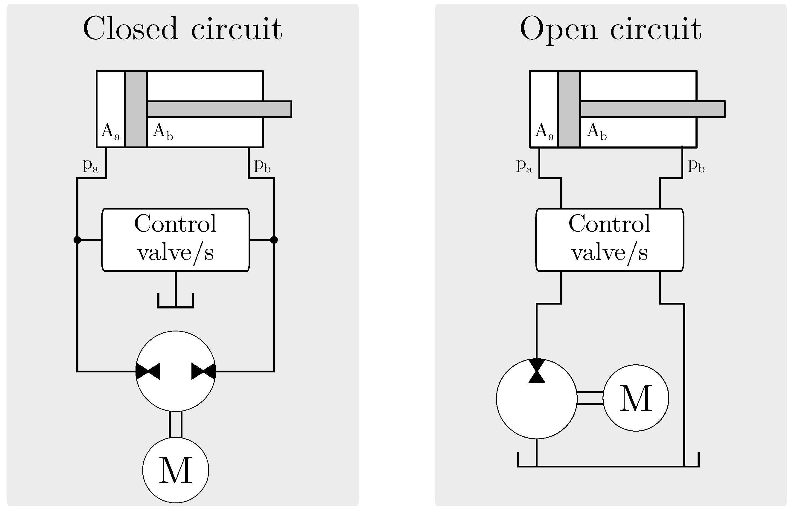
2. Considered Circuits

There are numerous ways to implement the circuits illustrated in Figure 1. However, they all have common features. All closed circuits must be able to change the side to which the reservoir is connected. This feature can be represented by two orifices. Open circuits, on the other hand, require four orifices - two that decide to which sides the pump is connected and two for the reservoir.
With the generalized circuits, multiple driving modes are possible. But in this paper, only the fundamental modes that are based on fully opened valves, where the pump flow controls the speed of the actuator, are considered. One mode for each quadrant of operation is then obtained, where the quadrants are defined by the direction of the actuator and the pressure difference. How the closed and open circuit operate in the different modes is illustrated in Figure 2 and Figure 3. The denotations Q1 to Q4 will hereafter be used to describe the quadrants.

2.1. Circuit Requirements

The circuits illustrated in Figure 2 and Figure 3 are generalised and somewhat simplified. It should therefore be clarified that the reservoirs ideally should be pressurized and that some kind of load-holding functionality might be required as well as a filtering solution.

2.1.1. Pressurised Reservoir

As seen in Figure 2, fluid will go from the reservoir to the cylinder or the pump via the orifice in Q1 and Q2 for closed circuits. The reservoir pressure must therefore be sufficiently high to avoid cavitation. The same applies to Q2 and Q4 for open circuits, which can be seen in Figure 3. In open circuits, all flow to the cylinder will pass the orifice, and larger valves or higher reservoir pressure compared to closed circuits, where only the differential flow between the cylinder chambers passes through the orifice, is therefore required.

2.1.2. Filtering

Filters can be placed at various places in hydraulic circuits, but they are usually designed for only allowing flow in one direction. In the generalized circuits that are presented in this paper, flow can go in both directions. This must be handled. Furthermore, the pressure drop over the filter will increase the requirements on the reservoir pressure.

2.1.3. Load-Holding Functionality

Safety regulations require some machines (e.g., cranes and earth-moving machinery) to be equipped with some kind of load-holding valves [40,41]. This is to avoid rapidly falling loads in case of failure. However, some kind of load-holding functionality is also desired when you want to be able to hold a load without having to apply torque to the prime mover. This functionality is principally already built-in in open circuits, even though it likely does not fulfill the safety requirements, but closed circuits require additional valves to obtain the functionality. The valves can be placed on the pump or the cylinder side, which is illustrated in Figure 4. Both alternatives are analyzed in this paper. More on that in Section 4. Any safety requirements are not considered.

3. Hysteresis Control

If the switching dynamics of the valves are neglected, the circuits can be considered as hybrid dynamical systems, i.e., dynamical systems with both discrete and continuous behavior. For this application, each mode of operation has its own continuous dynamic behavior, and the switching logic of the valves defines discrete jumping between the modes. A common approach to avoid problems with mode-switch oscillations in hybrid systems is to use make use of hysteresis [42]. This means that the switching condition depends on the switching direction, as illustrated in Figure 5 where the variable x can be an arbitrary property that defines the switching condition and h is a measure of the hysteresis width. A visualization of this in a pump-controlled system, where the pressure difference Δ p is used to decide when to switch mode, is shown in Figure 6.

3.1. Hysteresis Width Limitations

If the closed circuit is considered and if the pressure drops over the valves are neglected, the only pressure difference that can be measured is Δ p = p a p b , where the index a corresponds to the piston side and b to the rod side in accordance with the notations in Figure 1. In the first quadrant Q1, p b = p t , where p t is the reservoir pressure. For a mode-switch to occur, the differential pressure must satisfy Δ p < h , which means that p a < p t h . Therefore, the reservoir pressure limits the hysteresis width. The same reasoning applies to the other quadrants. If anti-cavitation valves are implemented, they must allow the pressure to go below the reservoir pressure, either by being connected to another reservoir with lower pressure or by being installed with sufficient cracking pressure.

3.2. Implementation

There are several ways to obtain hysteresis, both passively and actively. Different approaches are discussed below. This paper is focusing on the first two ones: active hysteresis and pressure-drop hysteresis. The last two have not been analyzed in detail and are only mentioned to exemplify the possibilities.

3.2.1. Active Hysteresis

To build in hysteresis in an electronic control unit that controls valve positions and motor speed can be considered as the most flexible and straightforward approach. This is the method that is used in the simulations presented in Section 5 and also what is meant when it later is refereed to active hysteresis. A drawback is that it requires electronically controlled valves. As mentioned in Section 3.1, it also puts high demands on the reservoir pressure.

3.2.2. Pressure-Drop Hysteresis

Pressure drops in hoses and valves can have a major impact on the static pressure levels in the system. By sensing pressures in certain ways, the change in static pressure level for a mode-switch can contribute to hysteresis, meaning that the static pressure difference moves away from the switching region. In other words, pressure-drop hysteresis is a consequence of the circuit type, the placing of load-holding valves, and pressure sensing components. Pressure-drop hysteresis for different circuits is calculated and presented in Section 4.

3.2.3. Hydro-Mechanical Hysteresis

Pressure-drop hysteresis can be considered as a type of passive hysteresis. Passive hysteresis can also be achieved in other ways. Hysteresis can be obtained if a force that opposes the movement of the valve is applied. The friction force within the valve has this functionality. However, it might be difficult to control the friction force. A hydro-mechanical solution that relies on pressure signals could therefore be more reasonable. Examples of possible implementations for closed and open circuits are shown in Figure 7. The examples rely on a pressure intensifier and a 4/2-valve. The latter is mechanically linked with the main valve. The arrangements make sure that the intensified pressure wants to keep the main valve in its current position whilst the reservoir pressure works in the other direction. The difference between these pressures defines the hysteresis width.
Since the reservoirs are supposed to be pressurized, one can also think of solutions where the reservoir pressure is working against the atmospheric pressure. That might, however, be a less attractive solution since there will be leakage to the atmospheric pressure which means that the pressurized reservoir regularly must be recharged. Nevertheless, it should be stated that the circuits in Figure 7 have not been evaluated and they should only be considered as principal ideas.

3.2.4. Active Throttling

An active approach that can reduce the requirements on the reservoir pressure is active throttling. A hysteresis mode is then introduced, as shown in Figure 8. In this mode, the flow from the return side of the cylinder is throttled. This requires proportional valves. For closed circuits, they must be on the cylinder side. The throttling mode can be considered as an extension of the pumping mode. Operation in the throttling mode is related to losses. However, since the mode only is active at low-pressure differences, the losses are likely small. Either way, active throttling is considered as out-of-scope for this paper and will not be further analyzed here.

4. Where to Sense the Pressures

The pressures can be sensed at both sides of the load-holding valves, and it is not obvious to decide where to sense the pressures. Depending on the circuits, the pressure-drop hysteresis will vary. In this section, it is analyzed how it will vary. The circuits that are analyzed in detail are shown in Figure 9. The circuits are based on where the pressure difference is sensed, and for closed circuits, the placement of the load-holding valve is also varied. The denotations C1 to C4 and O1 to O2 will hereafter be used to describe the different circuit configurations. In all configurations, it is assumed that all pressure drop between the pump and the cylinder is taking place in the load-holding valves. Pressure drop over hoses can be considered as neglected or lumped into the pressure drop over the load-holding valves. Note that more configurations are available if one allows mixed configurations, where the load-holding and pressure sensing components are separated (e.g., sensing at the cylinder on the a-side and at the pump on the b-side). To enhance readability, such configurations are excluded from this paper. However, the calculations that are presented in this section have also been conducted for mixed configurations and the results showed that they behave similarly to the presented ones.

4.1. Positive and Negative Pressure-Drop Hysteresis

When switching from Q1 to Q2 or from Q4 to Q3 (i.e., when moving in the negative Δ p -direction), a negative shift in Δ p is desired, and when switching from Q2 to Q1 or Q3 to Q4 (i.e., when moving in the positive Δ p -direction), the shift should be positive. It can be assumed that this has a positive impact on the switching behavior since the static pressure then is moved away from the switching region. Opposite signs would cause the static pressure to move back to values that correspond to the previous quadrant, and it will in turn call for another quadrant switch. Instability might thereby occur. In this paper, the term negative pressure-drop hysteresis will be used when the shift in static pressure is in the undesired direction along the Δ p -axis. A positive change in Δ p can therefore mean negative pressure-drop hysteresis. This is illustrated in Figure 10.

4.2. Pressure-Drop Hysteresis Calculations

For configuration C1, where the pressure sensing and load-holding are on the cylinder side, the hysteresis for a switch from Q1 to Q2 can be calculated as follows. Denotations are clarified in Figure 11.
The pressure drops are calculated according to Equations (1) and (2):
Δ p a = v A a c a ,
Δ p b = v A b c b .
The pressures in the system can be expressed as:
p a c = F + p b c A b + b v A a ,
p b c = p b p + Δ p b ,
p a p = p a c + Δ p a ,
p b p = p t v ( A a A b ) c t .
If the pressure signals that define the switching condition are set equal (in this case p b c = p a c ) and the equations above are solved for F, the external force at which switching occurs is obtained. This force can then be used when calculating the pressures in mode 2 (here denoted with the superscript ), where the pressures are calculated as follows:
p b c = F + p a c A a b v A b ,
p a p = p t v ( A a A b ) c t ,
p b p = p b c Δ p b ,
p a c = p a p Δ p a .
The shift in static pressure (i.e., the pressure-drop hysteresis) between Q1 and Q2 is then the difference between the sensed pressures. Since the x-axis for the quadrants has been defined as p a p b , the following hysteresis is obtained:
Δ p h y s t e r e s i s = p a c p b c .
If the Equations (1)–(10) are solved and put in (11), the following expression for the pressure-drop hysteresis is found:
Δ p h y s t e r e s i s = ( A a A b ) ( A b c a + A a c b ) v A b c a c b .
In the earlier discussion about pressure-drop hysteresis in Section 4.1, it was stated that a positive Δ p h y s t e r e s i s is undesired when switching from Q1 to Q2 since it corresponds to negative pressure-drop hysteresis. From Equation (12), it can be seen that the only way to change the sign of Δ p h y s t e r e s i s is to either change cylinder direction or to make A a smaller than A b . However, none of these changes are valid since they principally correspond to other quadrants, and Equation (12) only applies to a switch from Q1 to Q2. Configuration C1 for an asymmetric cylinder will hence always have negative pressure-drop hysteresis for this quadrant switch if v 0 .
The pressure-drop hysteresis has been calculated with the same train of thought for the other configurations and quadrant switches (i.e., 24 cases). The equations are left out from this paper, but the outcome showed that the parameter values cannot affect the signs of the pressure-drop hysteresis for any mode-switch in any configuration. Furthermore, from the equations, it can also be observed that the conclusion above also applies to non-linear pressure drops. For switching from Q1 to Q2 in configuration C1, this becomes clear if Equation (12) is rewritten as:
Δ p h y s t e r e s i s = A a A b A b ( Δ p a + Δ p b ) .
Δ p a and Δ p b are the pressure drops over the load-holding valves and since the pressure drops always will be positive, even if they are not linearly dependent on the flow, they cannot affect the sign of the pressure-drop hysteresis.
Nevertheless, with linear models and parameter values according to Table 1, the change in static pressure when switching between different quadrants is shown in Table 2 is obtained.
When only considering the signs, it can be seen that switching from Q3 to Q4 has the same influence on the static pressure as switching from Q1 to Q2, and that switching from Q4 to Q3 has the same effect as switching from Q2 to Q1. Nevertheless, when switching from Q1 to Q2, it is desired to have a negative shift in static pressure, but when switching from Q3 to Q4, a positive shift is desired. According to this static analysis, one can therefore expect smooth switching during load transition when running in one direction, but problems with oscillations in the other for configurations C1, C4, and O1. For configurations C2, C3 and O2, there is no pressure-drop hysteresis. For these configurations, one can therefore expect similar behavior in both directions. Whether the reasoning is valid when dynamics is included has been analyzed in computer simulations. The analysis is presented in Section 5.

5. Dynamic Analysis

Each system configuration can be described by a linear model for each quadrant. The results presented later are based on such models that have been solved in Simulink (Bogacki-Shampine, fixed time step of 1 × 10 5 s). In Q1, closed-circuit systems with load-holding valves on the cylinder side (configurations C1 and C2) can be described by the following equations:
d p a p d t = β V a p ( q i d e a l q l e a k q a ) ,
d p a c d t = β V a c ( v A a + q a ) ,
d p b p d t = β V b p c t ( p t p b p ) q i d e a l + q l e a k + q b ,
d p b c d t = β V b c ( v A b q b ) ,
where
d v d t = 1 m ( p a c A a p b c A b F v b ) ,
q i d e a l = v r e f A a ,
q l e a k = c p ( p a p p b p ) ,
q a = c a ( p a p p a c ) ,
q b = c b ( p b c p b p ) .
For load-holding valves on the pump side (configurations C3 and C4), the pressures can instead be described as follows. The velocities and flows are calculated as above.
d p a p d t = β V a p ( q i d e a l q l e a k q a ) ,
d p a c d t = β V a c ( v A a + q a ) ,
d p b p d t = β V b p ( q i d e a l + q l e a k + q b ) ,
d p b c d t = β V b c c t ( p t p b c ) + v A b q b .
Lastly, for the open circuits (configuration O1 to O4), the pressures can be described as:
d p a p d t = β V a p ( q i d e a l q l e a k q a ) ,
d p a c d t = β V a c ( v A a + q a ) ,
p b p = p t ,
d p b c d t = β V b c ( v A b q b ) .
It can be noticed that the equations for the closed circuit with load-holding valves on the cylinder side and the open circuit are identical if it is assumed that p b p = p t . Their dynamic behavior is therefore expected to be similar for large c t -values.
Figure 12 shows the step response from external force to sensed pressure difference for the different configurations in different quadrants. Parameter values are set according to Table 1 and Table 3. It is noticeable that the closed-circuit configurations with load-holding valves on the pump side (C3 and C4) are more oscillatory compared to the other configurations. This is due to the comparatively large c t -value. Furthermore, it can be observed that Q2 and Q3 are less oscillatory compared to Q1 and Q4 since the larger cylinder area then is connected to the reservoir.

5.1. Valve and Motor Dynamics

When mode switches occur, the orifices that correspond to the control valves will open or close and the motor speed will adapt to try to keep the cylinder speed constant. Here, the speed of the hydraulic machine as well as the valves’ pressure-flow coefficients are modeled with second-order dynamics. To see the impact of the motor dynamics, fast and slow cases are evaluated. Regarding the valves, the results presented here are for unrealistically fast valve dynamics. This is to keep the analysis general and avoid phenomena caused by the valve design/setup itself.

5.2. Worst Case: External Force Considerations

The system has two inputs: the external cylinder force and the cylinder speed command. It is expected that the most critical cases regarding mode-switch oscillations are when there is a step input to one of the signals and the external force corresponds to a value that gives static pressures close to the switching condition (e.g., when p a c = p b c ). If pressure drops are neglected, this force is when the external force is F = p t ( A a A b ) b v . However, when the effect of pressure drops is included, the force also depends on the configuration as well as the quadrant in operation (see Section 4). To obtain a fair comparison between different configurations and quadrant switches, the pressure drops are considered and therefore the external force is adapted to each case.

5.3. Open Loop Analysis: Switching without Pressure Feedback

To better understand the behavior of systems with closed-loop control, where feedback from the pressure difference is used to control the switching between quadrants, the pressures of switches without feedback are analyzed.
Figure 13 shows how the sensed pressures are affected during switching between different quadrants for different configurations with fast motor dynamics.
From the figure, it can be observed that the response for a switch from Q1 to Q2 is the mirror of the switch from Q4 to Q3. The same applies from Q2 to Q1 and Q3 to Q4. It can also be seen that configurations C2, C3, and O2 are less sensitive to mode-switches compared to C1, C4, and O1. In C2 and O2, no oscillations are visible and in C3, the oscillations are small. When looking at configuration C1, C4, and O1, the static offsets that were calculated in Section 4 are visible. However, it becomes evident that dynamic phenomena might cause problems in certain cases, e.g., when switching from Q4 to Q3 in configuration C1. In that case, there is a static offset in the desired direction. However, the pressure on the a-side is increased faster than on the b-side. This means that the sensed pressure difference first will move in the undesired direction before it settles at a value that corresponds to positive hysteresis.
It is also reasonable to assume that motor dynamics will have an important impact on the switching behavior since it in closed circuits must adapt the speed and in open circuits, it must also change direction. Figure 14 shows the same thing as Figure 13, but with slower, and more realistic, motor dynamics. It shows similar results, but the oscillations are generally amplified, especially in configuration O2.

5.4. Closed Loop Analysis: Switching with Pressure Feedback

To compare the risk of oscillations in each configuration, the systems are here excited with a step in external force of varying amplitude and varying active hysteresis width. The end value of the step corresponds to the worst-case described in Section 5.2. The time between the first and last switch is used as a performance measure. The measure is closely related to the number of switches, but it values cases with low switching frequency equal to cases with high frequency. The result for fast motor dynamics is shown in Figure 15.
The yellow areas in Figure 15 correspond to very poor switching behavior. It is apparent that it is mainly the cases with negative pressure-drop hysteresis that suffers from long switching times, but they also exist in other cases when there is no active hysteresis applied. The active hysteresis that is required to get out from the yellow regions is almost independent of the step amplitude. This indicates that it is the switch itself that excites the system. Outside the yellow regions, the figure generally shows a close to a linear relationship between the required hysteresis width and step amplitude for a certain time. It can also be seen that the configurations that are less damped have longer switching times for the same hysteresis width and force amplitude.
Another noticeable detail is that the switching behavior from Q1 to Q2 is very similar to the behavior from Q4 to Q3 for configurations with no pressure-drop hysteresis. The same applies in the opposite direction. This is expected since Q1 and Q4 are equal when it comes to dynamic response, and so are Q2 and Q3. It can also be seen that configuration C1 is very similar to O1, and that C2 is very similar to O2 except for when there is no hysteresis applied.
Regarding the initial dynamic effects that were observed in Figure 13 and Figure 14, one can notice that the negative impact of the initial pressure spike in configuration C1, when switching from Q4 to Q3, is not visible, but the corresponding spike in the less damped configuration C4, when switching from Q1 to Q2, can be seen. Another detail that can be noticed is that switch from Q2 to Q1 in configurations C1 and O1 are not as bad as expected.
Figure 16 shows the same simulations as Figure 15, but with slow motor dynamics. The results are similar to the ones presented in Figure 15. The main difference is that large yellow regions now not only appear in cases with negative pressure-drop hysteresis.

6. Discussion

When comparing closed and open circuits, it can be noted that both architectures share some issues:
  • They require pressurized reservoirs
  • Their filtering systems must be able to handle flow in both directions
  • Pump flow compensation is required to avoid a change in cylinder speed when switching between Q1 and Q2 or Q3 and Q4
  • They can suffer from mode-switch oscillations
This analysis has also shown that they have similar oscillation behavior if the motor and valve dynamics are neglectable and if the pressure drop between the reservoir and the system is small. However, with motor dynamics included, the open circuit behaves worse. An explanation is the fact that the hydraulic machine must change direction when switching mode, and not only the amplitude. Open circuits do, on the other hand, put less strict requirements on the pump design since the pump can have a defined high-pressure side. Another advantage of the open circuit architecture is regarding the flexibility. If load-holding valves are included in the closed circuit, both open and closed circuits require four orifices. However, the architecture of the open circuit offers a higher degree of flexibility. For example, the cylinder chambers can be connected to the tank and thereby allow for fast lowering motions. This can also be achieved in closed circuits, but additional valves are then required.
When it comes to where to sense the pressures, the presented analysis has shown that the placing of the pressure sensing components can have a great impact on the switching behavior. It can be concluded that it is not desired to have a hysteresis that is obtained by the pressure drops in the system, and the pressure sensing components should therefore be placed accordingly. The reason why to avoid pressure-drop hysteresis is mainly because it introduces undesired oscillations in the system. It is, however, not only the static pressure shift that matters but also the dynamics. Still, it is primarily negative pressure-drop hysteresis that should be avoided, but since positive pressure-drop hysteresis in one direction means negative pressure-drop hysteresis in the other, pressure-drop hysteresis, in general, is not desired.
When looking at previous work on closed circuits where pressure drop has been considered, it can be noted that pressure sensing has most often been set up in a way that pressure-drop hysteresis is avoided. That is, however, not the case for open circuits where the cylinder pressures tend to be used to decide when to switch mode.
Nevertheless, in this paper, it has become clear that all configurations can suffer from significant oscillations, even if there is no pressure-drop hysteresis. Active hysteresis has been proposed as a solution. The analysis has shown that active hysteresis can stabilize systems and reduce oscillations efficiently and that increased hysteresis width almost exclusively means improved performance. In summary, one can therefore say that it is preferred to have a configuration without any pressure-drop hysteresis, but an active hysteresis in the controller. It is, however, hard to know how much active hysteresis is required. The risk of having a pressure oscillation around the switching condition as well as the amplitude of the excitation must be considered. Also, motor dynamics play a role. Since the hysteresis puts higher demands on the reservoir pressure, a very high hysteresis can be inappropriate. A solution to this could be active throttling, which was presented in Section 3.2. But it must be evaluated further. Furthermore, if a passive solution with a similar impact as active hysteresis is desired, the hydro-mechanical solution presented in Section 3.2 could be interesting to investigate. But also that solution must be analyzed in more detail since it is possible that the pressure build-up phase can have a negative impact on the performance.
This analysis has shown that motor dynamics are important, but the valve dynamics will also have a great impact on the switching behavior. And it is not only the response that matters, but also the valve design itself (e.g., the underlap). This impact has, however, been left out from this analysis since we wanted to keep the analysis general and independent on any specific valve design. Still, during the work, it was observed that slow valve dynamics sometimes could reduce the oscillations that were introduced from the motor dynamics.
The models that are analyzed in this paper are linear and very simple. For example, pressure drops have only been considered as present at certain points. In real life, pressure drops occur everywhere, and they might not be linear. Still, the analysis provides information on the best placing of the pressure sensing components. It should also be stated that the presented results are based on only one set of parameter values (except for the motor dynamics). When it comes to the pressure-drop hysteresis, it was, however, observed that the parameter values only have an impact on the amplitude, not the sign, and one can generally say that a smaller amplitude means less impact (i.e., the difference between the pressure sensing alternatives will be smaller). Furthermore, variations in parameters naturally also affect the dynamic response for the different analyzed configurations. For example, if the flow coefficients c a and c b are closer to c t , the dynamics of C3 and C4 would be more comparable to C1, C2, O1, and O2. C1 and C2 would, however, still be more damped. Moreover, if c a and c b are increased, the pressure-drop hysteresis would be reduced meaning that the difference between the different pressure sensing alternatives would be smaller.
Lastly, it should be clarified that a kind of worst-case scenario is analyzed in this paper, meaning that the static pressures are at the switching condition (without active hysteresis). The external force that is required to obtain this depends on the system configuration and the operating quadrant. To make a fair comparison between different systems and to be able to draw general conclusions, it is therefore important to adapt the load case. That applies to any type of input signal, and not just steps that have been tested here. This is something that has not been considered in earlier system comparisons. When mode-switching behavior is analyzed and different systems are compared, the common approach has been to ramp an external force in some way. A potential problem with this is that switching conditions will be fulfilled at different cylinder positions, meaning that the system dynamics can be completely different. The risk is then that the conclusions only are valid for the tested load cases. It is especially important to consider this if widely different switching conditions are analyzed. Nevertheless, it is not likely that the worst-case scenarios that have been tested here will occur in the same manner in a real application. One can therefore expect fewer problems in reality than what has been shown in this paper. Still, configurations that have good worst-case performance can be expected to oscillate less in real life as well.

7. Conclusions

This paper has shown that it is desired to sense the pressure in pump-controlled systems in such a way that the sensed static pressure difference is unchanged after a mode-switch. Otherwise, there is a larger risk for mode-switch oscillations between certain quadrants to occur. It has also been shown that oscillations might occur in systems with proper pressure sensing, but that active hysteresis in the controller can reduce that risk. However, the pressure level in the reservoir must be sufficient to ensure controllability. Furthermore, it has been observed that closed circuits tend to suffer less from problems with mode-switch oscillations compared to the corresponding open circuits, especially if motor dynamics is considered. It could also be seen that the damping of the system has a clear influence on the switching behavior. The preferred system configuration from a mode-switching perspective is therefore configuration C2, where the load-holding valves are on the cylinder side and pressure sensing on the pump side. However, if an open circuit is desired, configuration O2, where the pressure sensing is on the pump side, is preferable.

Author Contributions

S.K.: idea formulation, conceptualization, modeling, writing, visualization. L.E.: supervision, editing. All authors have read and agreed to the published version of the manuscript.

Funding

This research was funded by Swedish Energy Agency grant number 44427-3.

Institutional Review Board Statement

Not applicable.

Informed Consent Statement

Not applicable.

Data Availability Statement

Not applicable.

Acknowledgments

The authors would like to thank Hudiksvall Hydraulics Cluster for their partnership in the project.

Conflicts of Interest

The authors declare no conflict of interest.

References

  1. Jalayeri, E.; Imam, A.; Tomas, Z.; Sepehri, N. A throttle-less single-rod hydraulic cylinder positioning system: Design and experimental evaluation. Adv. Mech. Eng. 2015, 7, 1687814015583249. [Google Scholar] [CrossRef] [Green Version]
  2. Jalayeri, E.; Imam, A.; Sepehri, N. A throttle-less single rod hydraulic cylinder positioning system for switching loads. Case Stud. Mech. Syst. Signal Process. 2015, 1, 27–31. [Google Scholar] [CrossRef] [Green Version]
  3. Rahmfeld, R.; Ivantysynova, M.; Eggers, B. Active Vibration Damping for Off-Road Vehicles Using Valveless Linear Actuators. In Proceedings of the SAE Commercial Vehicle Engineering Congress & Exhibition, Detroit, MI, USA, 8–11 March 2004; SAE International: Warrendale, PA, USA, 2004. [Google Scholar] [CrossRef]
  4. Williamson, C.; Ivantysynova, M. Pump mode prediction for four-quadrant velocity control of valueless hydraulic actuators. In Proceedings of the JFPS International Symposium on Fluid Power, Matsue, Japan, 28–31 October 2018; The Japan Fluid Power System Society: Tokyo, Japan, 2008; pp. 323–328. [Google Scholar] [CrossRef]
  5. Zakharov, V.; Minav, T. Analysis of Field Oriented Control of Permanent Magnet Synchronous Motor for a Valveless Pump-Controlled Actuator. Proceedings 2020, 64, 8491. [Google Scholar] [CrossRef]
  6. Bonato, C.; Minav, T.A.; Sainio, P.; Pietola, M. Position control of direct driven hydraulic drive. In Fluid Power Systems Technology; American Society of Mechanical Engineers: New York, NY, USA, 2014; Volume 45820, p. V001T05A007. [Google Scholar]
  7. Minav, T.A.; Sainio, P.; Pietola, M. Direct-driven hydraulic drive without conventional oil tank. In Fluid Power Systems Technology; American Society of Mechanical Engineers: New York, NY, USA, 2014; Volume 45974, p. V001T01A022. [Google Scholar]
  8. Lawrence, P.D.; Salcudean, S.; Sepehri, N.; Chan, D.; Bachmann, S.; Parker, N.; Zhu, M.; Frenette, R. Coordinated and force-feedback control of hydraulic excavators. In Experimental Robotics IV; Springer: Berlin/Heidelberg, Germany, 1997; pp. 181–194. [Google Scholar]
  9. Rahmfeld, R.; Ivantysynova, M. Displacement controlled linear actuator with differential cylinder—A way to save primary energy in mobile machines. In Proceedings of the ICFP 2001: Fifth International Conference on Fluid Power Transmission and Control, Hangzhou, China, 3–5 April 2001; pp. 296–301. [Google Scholar]
  10. Heybroek, K.; Palmberg, J.O. Evaluating a Pump Controlled Open Circuit Solution. In Proceedings of the International Exposition for Power Transmission, Nevada, USA: Proceedings of the 51st IFPE, Las Vegas, NV, USA, 12–14 March 2008; Omnipress: Madison, WI, USA, 2008; pp. 681–694. [Google Scholar]
  11. Ivantysyn, R.; Weber, J. Novel open circuit displacement control architecture in heavy machinery. In Proceedings of the 8th FPNI Ph. D Symposium on Fluid Power, Lappeenranta, Finland, 11–13 June 2014; American Society of Mechanical Engineers: New York, NY, USA, 2014. [Google Scholar] [CrossRef]
  12. Schneider, M.; Koch, O.; Weber, J. Green Wheel Loader–improving fuel economy through energy efficient drive and control concepts. In Proceedings of the 10th International Fluid Power Conference (10. IFK), Dresden, Germany, 8–10 March 2016; Volume 2, pp. 63–78. [Google Scholar]
  13. Schmidt, L.; Roemer, D.B.; Pedersen, H.C.; Andersen, T.O. Speed-Variable Switched Differential Pump System for Direct Operation of Hydraulic Cylinders. Fluid Power Syst. Technol. 2015, V001T01A042. [Google Scholar] [CrossRef]
  14. Qu, S.; Fassbender, D.; Vacca, A.; Busquets, E.; Neumann, U. A Closed Circuit Electro-Hydraulic Actuator with Energy Recuperation Capability. In Proceedings of the 12th International Fluid Power Conference, Online, 12–14 October 2020. [Google Scholar] [CrossRef]
  15. Fassbender, D.; Zakharov, V.; Minav, T. Utilization of electric prime movers in hydraulic heavy-duty-mobile-machine implement systems. Autom. Constr. 2021, 132, 103964. [Google Scholar] [CrossRef]
  16. Kärnell, S.; Fernlund, E.; Lagerstedt, F.; Ericson, L. Pump-Controlled Actuators with Dump Valves. In Proceedings of the 17th Scandinavian International Conference on Fluid Power, Linköping, Sweden, 1–2 June 2021. [Google Scholar] [CrossRef]
  17. Niraula, A.; Zhang, S.; Minav, T.; Pietola, M. Effect of zonal hydraulics on energy consumption and boom structure of a micro-excavator. Energies 2018, 11, 2088. [Google Scholar] [CrossRef] [Green Version]
  18. Zhang, S.; Minav, T.; Pietola, M.; Kauranne, H.; Kajaste, J. The effects of control methods on energy efficiency and position tracking of an electro-hydraulic excavator equipped with zonal hydraulics. Autom. Constr. 2019, 100, 129–144. [Google Scholar] [CrossRef]
  19. Ketelsen, S.; Padovani, D.; Andersen, T.O.; Ebbesen, M.K.; Schmidt, L. Classification and Review of Pump-Controlled Differential Cylinder Drives. Energies 2019, 12, 1293. [Google Scholar] [CrossRef] [Green Version]
  20. Hewett, A.J. Hydraulic Circuit Flow Control. US Patent 5,329,767, 19 July 1994. [Google Scholar]
  21. Rahmfeld, R. Energy saving hydraulic actuators for mobile machines. In Proceedings of the 1st Bratislavian Fluid Power Symposium, Casta-Pila, Slovakia, 2–3 June 1998; pp. 47–57. [Google Scholar]
  22. Williamson, C.; Ivantysynova, M. Stability and motion control of inertial loads with displacement controlled hydraulic actuators. In Proceedings of the 6th FPNI-PhD Symposium, West Lafayette, IN, USA, 15–19 June 2010; pp. 15–19. [Google Scholar]
  23. Michel, S.; Weber, J. Electrohydraulic compact-drives for low power applications considering energy-efficiency and high inertial loads. In Proceedings of the 7th FPNI PhD Symposium on Fluid Power, Reggio Emilia, Italy, 27–30 June 2012; pp. 27–30. [Google Scholar]
  24. Wang, L.; Book, W.J.; Huggins, J.D. A hydraulic circuit for single rod cylinders. J. Dyn. Syst. Meas. Control. 2012, 134, 011019. [Google Scholar] [CrossRef] [Green Version]
  25. Wang, L.; Book, W.J. Using leakage to stabilize a hydraulic circuit for pump controlled actuators. J. Dyn. Syst. Meas. Control. 2013, 135, 061007. [Google Scholar] [CrossRef]
  26. Çalışkan, H.; Balkan, T.; Platin, B.E. A complete analysis and a novel solution for instability in pump controlled asymmetric actuators. J. Dyn. Syst. Meas. Control. 2015, 137, 091008. [Google Scholar] [CrossRef]
  27. Çalışkan, H.; Balkan, T.; Platin, B.E. A Complete Analysis for Pump Controlled Single Rod Actuators. In Proceedings of the 10th International Fluid Power Conference (10th IFK), Dresden, Germany, 8–10 March 2016. [Google Scholar]
  28. Imam, A.; Rafiq, M.; Jalayeri, E.; Sepehri, N. Design, Implementation and Evaluation of a Pump-Controlled Circuit for Single Rod Actuators. Actuators 2017, 6, 10. [Google Scholar] [CrossRef] [Green Version]
  29. Imam, A.; Rafiq, M.; Jalayeri, E.; Sepehri, N. A Pump-Controlled Circuit for Single-Rod Cylinders that Incorporates Limited Throttling Compensating Valves. Actuators 2018, 7, 13. [Google Scholar] [CrossRef] [Green Version]
  30. Imam, A.; Rafiq, M.; Zeljko, T.; Sepehri, N. Improving the Performance of Pump-Controlled Circuits for Single-Rod Actuators. Actuators 2019, 8, 26. [Google Scholar] [CrossRef] [Green Version]
  31. Costa, G.K.; Sepehri, N. Four-quadrant analysis and system design for single-rod hydrostatic actuators. J. Dyn. Syst. Meas. Control. 2019, 141, 021011. [Google Scholar] [CrossRef]
  32. Koury Costa, G.; Sepehri, N. A Critical Analysis of Valve-Compensated Hydrostatic Actuators: Qualitative Investigation. Actuators 2019, 8, 59. [Google Scholar] [CrossRef] [Green Version]
  33. Koury Costa, G.; Sepehri, N. A Critical Analysis of Flow-Compensated Hydrostatic Single Rod Actuators: Simulation Study. Actuators 2020, 9, 58. [Google Scholar] [CrossRef]
  34. Gøytil, P.H.; Padovani, D.; Hansen, M.R. A Novel Solution for the Elimination of Mode Switching in Pump-Controlled Single-Rod Cylinders. Actuators 2020, 9, 20. [Google Scholar] [CrossRef] [Green Version]
  35. Zhang, S.; Li, S.; Minav, T. Control and Performance Analysis of Variable Speed Pump-Controlled Asymmetric Cylinder Systems under Four-Quadrant Operation. Actuators 2020, 9, 123. [Google Scholar] [CrossRef]
  36. Heybroek, K.; Larsson, J.; Palmberg, J.O. Mode Switching and Energy Recuperation in Open-Circuit Pump Control. In Proceedings of the 10th Scandinavian International Conference on Fluid Power, Tampere, Finland, 21–23 May 2007; Tampere University of Technology: Tampere, Finland, 2007; pp. 197–209. [Google Scholar]
  37. Heybroek, K.; Palmberg, J.O. Applied Control Strategies for a Pump Controlled Open Circuit Solution. In Proceedings of the 6th IFK: International Fluid Power Conference, Dresden, Germany, 31 March–2 April 2008; Dresdner Verein zur Förderung der Fluidtechnik e.V.: Dresden, Germany, 2008; pp. 39–52. [Google Scholar]
  38. Qu, S.; Vacca, A.; Fassbender, D.; Busquets, E. Formulation, Design and Experimental Verification of an Open Circuit Electro-Hydraulic Actuator. In Proceedings of the 2020 IEEE Global Fluid Power Society PhD Symposium (GFPS), Online, 19–21 October 2020. [Google Scholar]
  39. Qu, S.; Fassbender, D.; Vacca, A.; Busquets, E. A high-efficient solution for electro-hydraulic actuators with energy regeneration capability. Energy 2021, 216, 119291. [Google Scholar] [CrossRef]
  40. ISO 15442: Cranes—Safety Requirements for Loader Cranes; International Organization for Standardization: Geneva, Switzerland, 2012.
  41. ISO 8643: Earth-Moving Machinery—Hydraulic Excavator and Backhoe Loader Lowering Control Device—Requirements and Tests; International Organization for Standardization: Geneva, Switzerland, 2017.
  42. Liberzon, D. Switching in Systems and Control; Springer: Berlin/Heidelberg, Germany, 2003. [Google Scholar]
Figure 1. Generalised system architectures. Pilot-operated check valves or shuttle valves are often used in closed circuits. In open circuits, solutions with directional valves or multiple on/off valves can be found.
Energies 15 00424 g001
Figure 2. Working modes for a generalised closed circuit architecture.
Energies 15 00424 g002
Figure 3. Working modes for a generalised open circuit architecture.
Energies 15 00424 g003
Figure 4. Alternative placements for load-holding functionality in closed circuits.
Energies 15 00424 g004
Figure 5. Hysteresis control of a hybrid system. The variable x denotes an arbitrary property and h is the hysteresis width.
Energies 15 00424 g005
Figure 6. Hysteresis control in a pump controlled system where the switch is defined by the pressure difference Δ p and the hysteresis width h.
Energies 15 00424 g006
Figure 7. Examples of how hydro-mechanical hysteresis can be implemented. The circuits have not been investigated in detail.
Energies 15 00424 g007
Figure 8. Working principle for active throttling. The green areas called Th corresponds to the throttling modes. The method has not been investigated in detail.
Energies 15 00424 g008
Figure 9. Circuit configurations analysed in this paper.
Energies 15 00424 g009
Figure 10. Visualisation of pressure-drop hysteresis. Here, the pressure difference is linearly decreasing from a positive value to zero. At zero, there is a quadrant switch. If the pressure difference then is moved further down, it corresponds to positive pressure-drop hysteresis. If the switch causes the pressure difference to move back into the positive Δ p -region, it corresponds to negative pressure-drop hysteresis.
Energies 15 00424 g010
Figure 11. Clarification of denotations. The example shown is for operation in the first quadrant and the load-holding valves are on the cylinder side.
Energies 15 00424 g011
Figure 12. Step response from external force to sensed pressure difference.
Energies 15 00424 g012
Figure 13. Switch without pressure feedback between different quadrants for different configurations. The forced mode-switch occurs after 0.5 seconds. The cases with negative pressure-drop hysteresis are marked with solid red lines and the ones with positive are marked with dashed green lines.
Energies 15 00424 g013
Figure 14. Same as Figure 13, but with slow motor dynamics.
Energies 15 00424 g014
Figure 15. Time between first and last switch when a step in external force is applied for different quadrants and different configurations. The step was applied after 2 s and the simulation ran for 5 s, meaning that the maximum switching time was 3 s. The cases with negative pressure-drop hysteresis are marked with solid red lines and the ones with positive are marked with dashed green lines.
Energies 15 00424 g015
Figure 16. Same as Figure 15 but with slow motor dynamics.
Energies 15 00424 g016
Table 1. Parameter values.
DescriptionDenotationValueUnit
Reservoir pressure p t 1 × 10 6 Pa
Cylinder area, piston side A a 6.4 × 10 3 m 2
Cylinder area, rod side A b 3.5 × 10 3 m 2
Flow coefficient, piston side c a 1 × 10 9 m 3 / s / Pa
Flow coefficient, rod side c b 1 × 10 9 m 3 / s / Pa
Flow coefficient, tank c t 1 × 10 8 m 3 / s / Pa
Cylinder velocityv 4 × 10 2 m / s
Viscous frictionb 1 × 10 4 Ns/m
Table 2. Change in static pressure difference for different configurations when switching between different modes. Green colour corresponds to positive hysteresis and red to negative.
DenotationLHVpQ1 to Q2Q2 to Q1Q3 to Q4Q4 to Q3
PlacementSensing[MPa][MPa][MPa][MPa]
C1CylinderCylinder0.32−0.180.18−0.32
C2CylinderPump0000
C3PumpCylinder0000
C4PumpPump−0.630.35−0.350.63
O1-Cylinder0.32−0.180.18−0.32
O2-Pump0000
Table 3. Complementary parameter values for dynamic modelling. Parameters for motor dynamics are provided for two cases: slow and fast. If nothing else is stated, fast parameters are used.
DescriptionDenotationValueUnit
Pump volume, piston side V a p 1 × 10 3 m 3
Pump volume, rod side V b p 1 × 10 3 m 3
Cylinder volume, piston side V a c 5 × 10 3 m 3
Cylinder volume, rod side V b c 5 × 10 3 m 3
Bulk modulus β 1 × 10 9 Pa
Inertial loadm1000kg
Pump leakage c p 0 m 3 / s / Pa
Cylinder leakage c c 0 m 3 / s / Pa
Motor resonance frequency (fast) f m 1000Hz
Motor resonance frequency (slow) f m 20Hz
Valve resonance frequency f v 1000Hz
Motor damping ratio (fast) δ m 1-
Motor damping ratio (slow) δ m 0.3 -
Valve damping ratio δ v 1-
Publisher’s Note: MDPI stays neutral with regard to jurisdictional claims in published maps and institutional affiliations.

