Abstract
Suspended monorails are a common mode of transportation for materials and personnel in underground mines. The goal of the EU-funded project “Innovative High Efficiency Power System for Machines and Devices, Increasing the Level of Work Safety in Underground Mining Excavations (HEETII)” is to introduce a single-wire energy transmission system combined with a capacitive-coupling-based wireless transmission system to power the suspended tractor, along with a monitoring system that will monitor the energy network and additional environmental parameters of the mine. Additionally, the monitoring system acts as the wireless communication backbone, allowing for data transmission to surface headquarters, where the data are processed and logged in a central database. This enables operators to detect and take preemptive measures to prevent potential hazards in the mine, improving the overall efficiency of the energy transmission system. This paper describes the additional considerations required for electrical systems in underground mines with potentially explosive atmospheres, as well as the design of the energy transmission system and the monitoring system.
1. Introduction
Transport of materials and personnel is a critical task in mine operations [1]. A common solution—especially in coal mines in some parts of the world—is a suspended monorail system, since it is independent of the quality of the roadway floor [2]. Operating the monorails using diesel drive systems has major disadvantages, since the engines emit gases, heat, and noise, and require a fuel transport network with special safety requirements [3]. Therefore, battery-powered suspended monorail systems were developed. Recharging the batteries in underground mining conditions—especially in potentially explosive atmospheres—requires specially designed solutions. The “Innovative High Efficiency Power System for Machines and Devices, Increasing the Level of Work Safety in Underground Mining Excavations (HEET II)” project, supported by the Research Fund for Coal and Steel (RFCS)—developed by partners from Poland, Romania, and Germany—aims to improve the safety and efficiency of suspended monorail systems. The project’s goals can be divided into the following four parts:
- A single-wire energy transmission system along the monorail track;
- A capacitive-coupling-based wireless energy transmission system to recharge the batteries of the suspended tractor;
- A redesign of the suspended beam using composite materials;
- A monitoring and control system for the energy transmission network and environmental parameters in the underground mine.
This work introduces both the single-wire and wireless energy transfer systems developed jointly by the Silesian University of Technology and KOMAG Institute of Mining Technology in Poland, along with the monitoring system developed by the Institute for Advanced Mining Technologies (AMT) RWTH Aachen University.
2. Wireless Energy Transfer System
One of the actions that must be undertaken to charge battery-powered devices is to connect the plug that supplies the power. This is usually done by the user/operator of the machine. There are also solutions where the power is supplied by an automatically retracting pantograph (for high charging power, such as in buses). These seemingly simple operations for equipment used in underground mine conditions—especially those where a methane or coal dust explosion hazard can be expected—require specially designated rooms and connectors. A potential solution to the problem of battery charging of electrical machines operating in underground environments is the use of a wireless charging system. Systems of this type are used in consumer electronics—e.g., to charge the batteries of telephones or electric vehicles—and are constantly the subject of scientific analyses [4]. Depending on which element is responsible for the wireless energy transfer, these can be divided into systems with inductive (transformer) and capacitive coupling. Systems with inductive coupling are usually used for stationary operations. Recently, attempts were made to develop solutions for powering devices in motion [5,6]. The disadvantage of solutions with transformer coupling is the intense heating of metal objects that could be located near the interacting coils responsible for energy transfer, which is unacceptable under mining conditions. In environments where there is a risk of methane and/or coal dust explosion, it may be advantageous to use a system with capacitive coupling. Systems of this type have been the subject of various scientific analyses in recent years [7,8,9].
Another reason for developing a wireless energy transfer (WET) system is the need to increase battery runtime. This would increase the operational availability of the machine, and reduce the number of stops necessary for charging the battery. To apply wireless power transfer, the location of the coupling elements and the type of machine class being powered must be considered. It was decided to develop a system with capacitive coupling to power suspended tractors. The capacitors responsible for the coupling will be formed by electrodes installed in the suspended rail and electrodes moving along with the tractor. The suspended route will be made of a composite (dielectric) material. A system of this type has not yet been developed for underground mining.
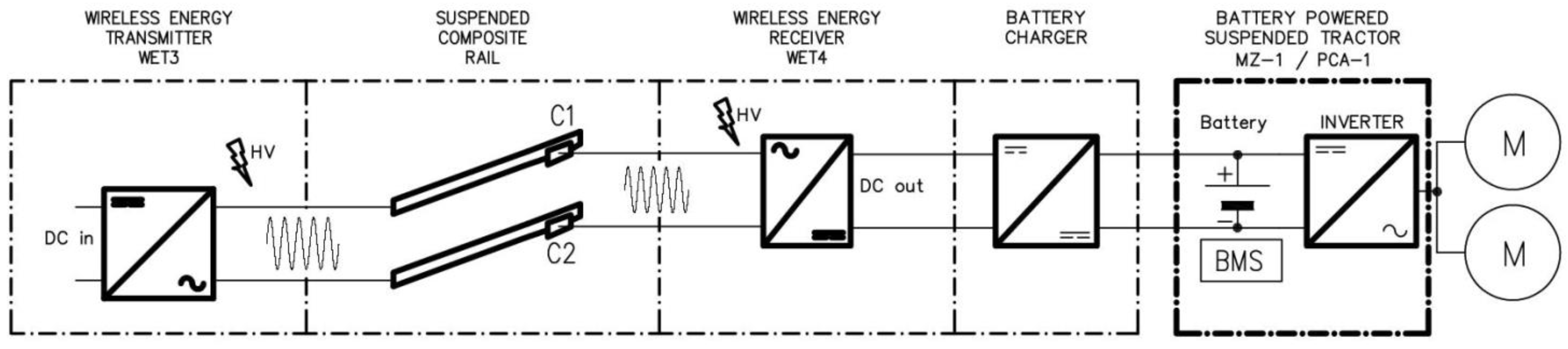
Figure 1 shows the principle of operation of a WET system, according to the idea presented above. The WET system transmitter (WET3) generates a high-voltage, high-frequency current, which is transmitted via capacitors to the receiver (WET4). The receiver then powers an additional charger, which replenishes the tractor’s battery. The prototype of the system will be tested with the PCA-1 type suspended accumulator tractor developed at ITG KOMAG [10]. In this solution, one plate of the capacitors C1 and C2 moves together with the suspended tractor.

Figure 1.
Concept of energy transfer in a WET system with capacitive coupling.
The transmitter of the WET system in the proposed solution is supplied with DC current. The current is supplied through a single-wire energy transfer (SWET) system, the scheme of which is shown in Figure 2. In this system, the high-voltage and high-frequency output current is transmitted from the transmitter to the receiver through a single wire. The electrical circuit is closed using either a ground or a return conductor. Systems of this type are known in the literature [11,12,13], and are readily used in sparsely urbanized areas [14]; however, they have not been used in underground mining. In the planned system, the SWET also provides a three-phase output, compatible with the parameters of the mains supply. Selected issues related to the efficiency of the developed system are presented in [15].
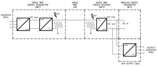
Figure 2.
The scheme of energy transfer in an SWET system.
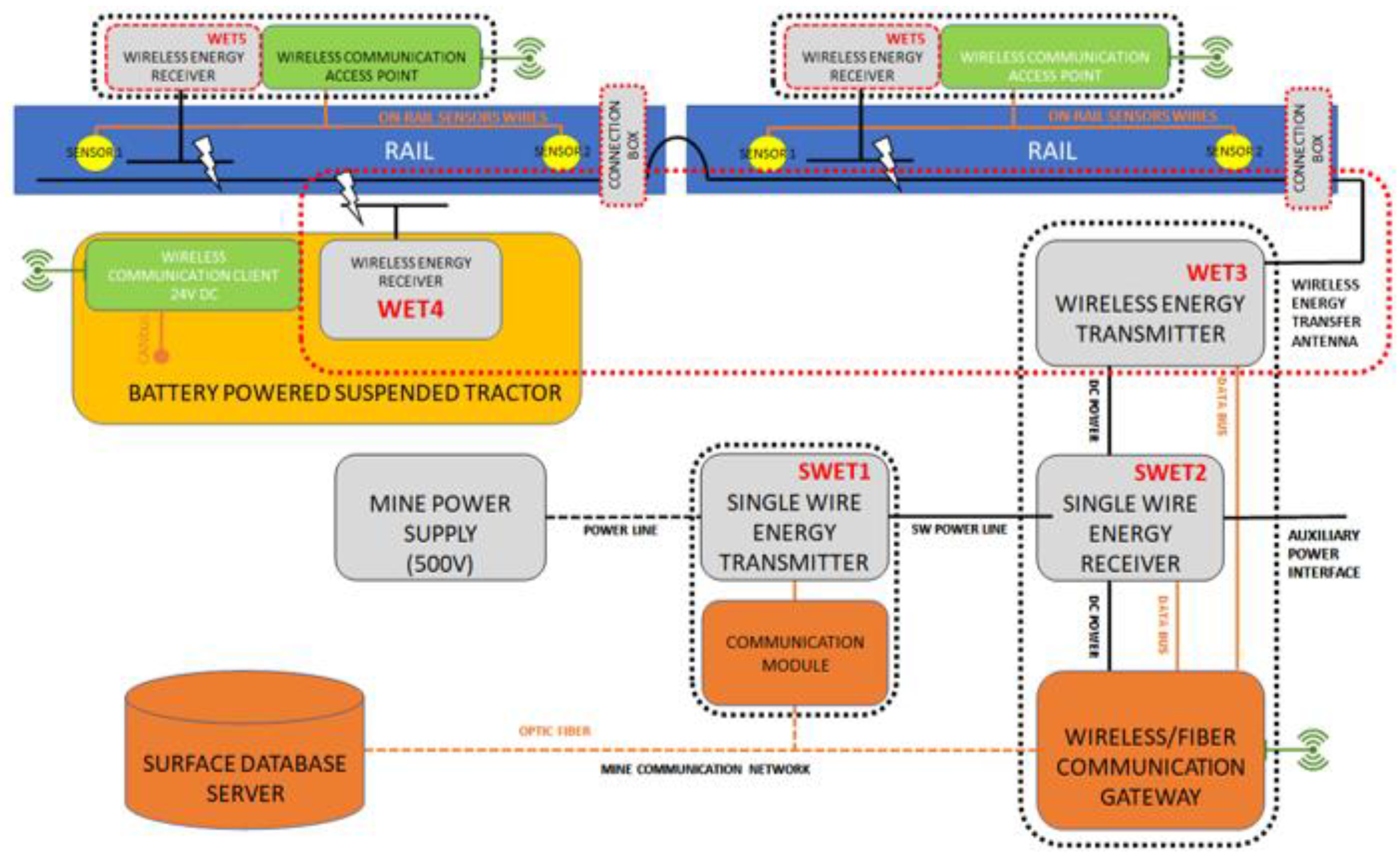
The schemes shown in Figure 1 and Figure 2 are part of a larger system being developed within the HEET II project. The concept of this system is presented in Figure 3. The solution is designed to transmit energy wirelessly, particularly to receivers on the move. This will extend the battery runtime of devices moving along the suspended route. Hence, a suspended tractor (BATTERY POWERED SUSPENDED TRACTOR) was selected as an example machine with a WET receiver. To achieve the capacitive coupling, it is necessary to change the construction of the suspension route rails (RAIL), which will be made of a composite material. A pair of capacitor plates will be incorporated into the structure. The second pair of plates will move with the tractor, forming the capacitive coupling. The capacitive coupling cooperates with the power electronics modules, as well as the high-frequency and high-voltage energy transmitter (WET3) and receiver (rectifier, WET4). In the proposed solution, the WET3 module is powered by a single-wire energy transfer system (Figure 2). More details related to the development of the WET power system are presented in [16].

Figure 3.
Concept for an innovative power supply system being developed within the HEET II project [16].
As can be seen in Figure 3, an important part of the overall system is the subsystem related to communication and monitoring of environmental parameters along the suspended route. The communication subsystem uses wireless transmission between the suspended tractor, the energy transmitter module of the WET system (WET3), and the sensor and communication modules (access points) associated with the suspended route. To eliminate the need to run power cables to these sensor and access point modules, they were also equipped with the WET wireless power system. The latter is a low-power system; the capacitive coupling is achieved using a pair of fixed plates placed on the suspended track, together with a pair of plates placed on the suspended track. In this case, the capacitor plates placed on the composite rail form a common power bus, both for the receiver in the suspended tractor and for the receivers in the access point modules. The system shown in Figure 1 is extended with additional power components, as shown in Figure 4.
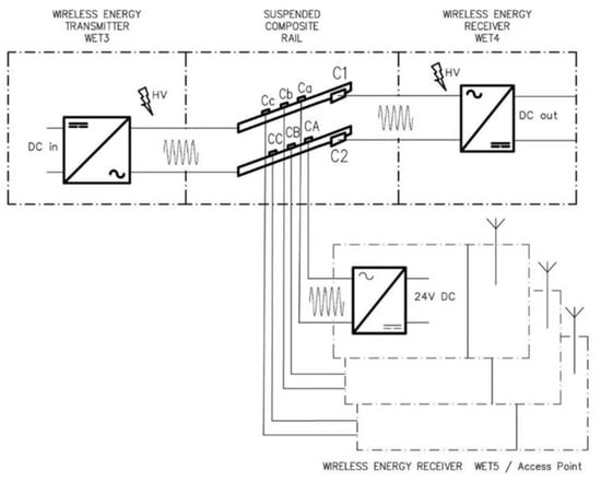
Figure 4.
Concept of energy transfer in a WET system with additional low-power energy receivers to supply access points via capacitive coupling.
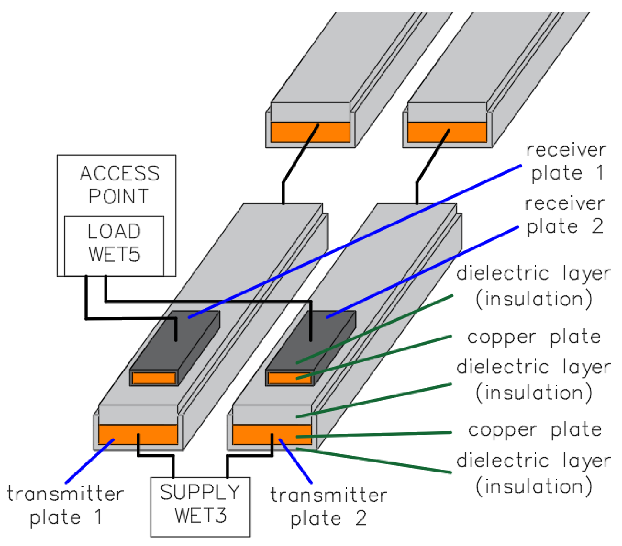
As mentioned, wireless energy transfer occurs using capacitive coupling capacitors. The receiver plates, which form the capacitors for powering the access point, are located on the suspended rail, but are not permanently connected to it. The power transmitter plates are built into the suspended rail. An illustration of the construction of one of these capacitive couplings is shown in Figure 5.

Figure 5.
Capacitive coupling—a key component of a wireless energy transfer system.
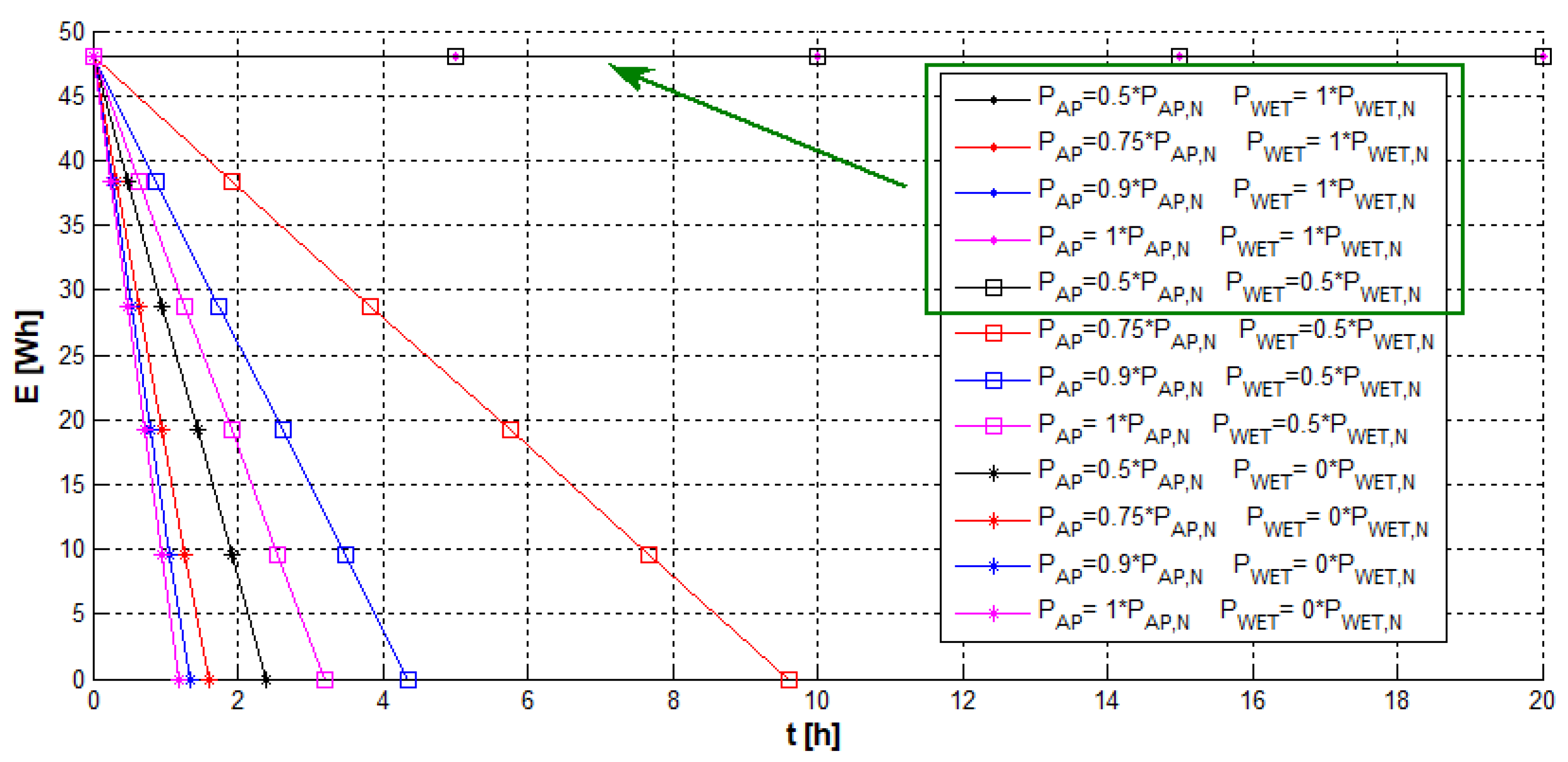
The use of wireless power supply and communication facilitates the relocation of the communication–sensory module and its use—for example, for ad hoc monitoring of parameters in different areas of a mine. Thanks to the possibility of battery operation, it can periodically work away from the source of its power supply, i.e., from the composite rail with built-in capacitive coupling. Thanks to the built-in battery, the communication module can also operate in the event of a power supply outage, or in cases where the power acquired by the WET5 receiver is periodically less than required by its individual subunits. Figure 6 shows the results of a simplified simulation related to the operation time of the communication module by the WET receiver with battery only (WET receiver power PWET = 0 W), and at different power levels. Several levels of power load by internal systems were assumed, related for example to the task of charging the built-in battery. For the calculations, the nominal power of the communication module was assumed as PAP,N = 40 W, the nominal power of the WET receiver as PWET,N = 50 W, and the nominal energy accumulated in the battery as EN = 48 Wh. As can be seen from the simplified simulations, the battery-only operating time is ~1.5–2.5 h. The use of a power supply with a WET receiver allows for a longer operating time. When the energy consumed by the WET receiver exceeds the energy consumption of the communication–sensory module, its uninterrupted autonomous operation is possible, independent of the mine’s power supply network.
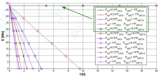
Figure 6.
Results of a simplified simulation of a change in the remaining energy in the battery during operation, depending on the access point’s load and the extracted power from the WET system (PWET,N = 50 W, PAP,N = 40 W).
For the energy transfer to be realized through the capacitive coupling shown in Figure 5, it is necessary to determine the required capacitance of the coupling, which translates into the length of the receiving plates. Preliminary measurements of capacitance as a function of frequency have been carried out to estimate the equivalent parameters of the capacitor (series resistance, capacitance) formed by the pair of plates. Example characteristics are presented in Figure 7. A detailed description of these measurements can be found in [16].
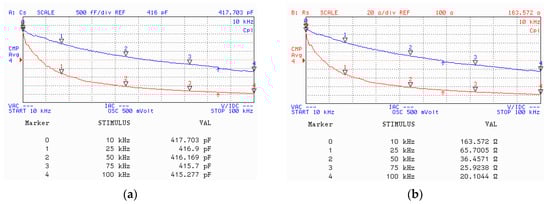
Figure 7.
Equivalent capacitance CS (a) and resistance RS (b) for the distance of 7 mm (dielectric layer) as a function of the frequency [16].
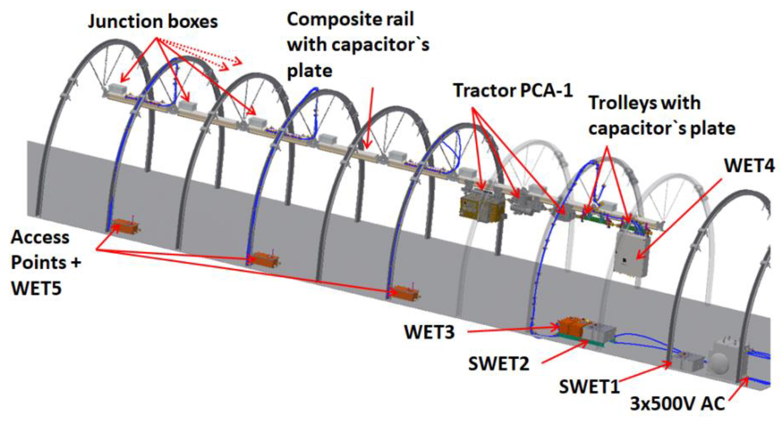
Activities carried out in the HEET II project are currently focused on the preparation of prototypes of individual subsystems, in order to carry out research. One of the research stages is functional testing, to be carried out under in situ conditions, in the roadway of the “Barbara” Experimental Mine in Mikołów. Figure 8 presents a visualization of the system, which will be prepared for testing in the selected roadway, according to the concept presented in Figure 3. As can be seen, the tests assume the use of three modules for environmental monitoring and communication (access points).
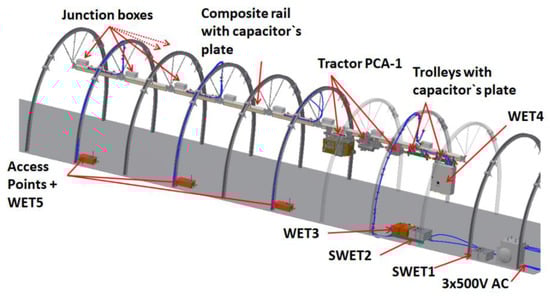
Figure 8.
Visualization of the main modules associated with the WET system [16].
3. Underground Mine Hazardous Gas Monitoring Literature Review
The presence of hazardous gases in underground mines puts a lot mental and physical stress on the miners [17]. Coal mines, in particular, often face an additional challenge due to the release of methane—a highly flammable gas that poses an explosive threat [18]. During normal operations, the ventilation system supplies fresh air, diluting and drawing out the heat, dust, and hazardous gases [19]. A failure of the ventilation system can therefore lead to major accidents, with damage to equipment, property, and even fatalities [20,21]. In the case of a ventilation system failure, a gas monitoring system could detect the build-up of hazardous gases and warn the mine operators, enabling them to react to the situation before any incidents take place [19].
Multiple systems for hazardous gas monitoring have been proposed. Ziętek et al. [22] proposed a portable system based on the Arduino platform, which measures the concentrations of hydrogen sulfide (H2S) and carbon monoxide (CO), and transmits them via Bluetooth. The data can then be viewed using any smartphone. Jo and Khan [23] also used an Arduino-based setup with multiple sensor nodes that transmit the data via ZigBee to a base station; their system tracks eight different parameters, but they determined the concentrations of methane (CH4), CO, sulfur dioxide (SO2), and H2S as being the most dangerous. Other works focus on similar setups, with most of them agreeing on measuring CO and CH4 concentrations [24,25,26].
Porselvi et al. [27] proposed a wearable system that simultaneously tracks SO2, CO, and nitrogen dioxide (NO2) concentrations, as well as vital parameters of the miners; if the system detects any irregularities, the data are transmitted using a LoRaWAN module. Behr et al. [28], and Charde [29] mentioned that head-mounted gas sensors are particularly suitable for this application.
The above-mentioned research focuses only on hazardous gas monitoring applications. In addition to monitoring the single-wire system, the system proposed in this paper is extendable, can transmit additional monitoring information for future use cases, and has the necessary infrastructure to transmit data to a central database in surface headquarters for further processing.
4. Proposed Monitoring System
The individual subsystems—SWET1, SWET2, WET3, WET4, and WET5—as shown in Figure 3, are continuously monitored, and the corresponding information is transmitted to a central database. A design assumption was made to save the data to the database once every 5 s. For signals with higher expected frequency changes (e.g., current drawn), the average and peak values of the 5 s time windows are saved in the database. Among the planned analyses, two of the most important are those concerning the transmitted power and the achieved energy transmission efficiency. These analyses will be performed on the database server. Information regarding the monitoring of system operations, the position of the tractor in the roadway, and its readiness for work will also be significant.
The single-wire systems SWET1 and SWET2 and the wireless energy transmitter WET3 communicate using the RS485 bus and Modbus RTU protocol, while the connections between individual modules and the database are handled using optical fibers. Information transmitted from the SWET and WET systems includes status data and measurement values concerning input and output voltages and currents, temperature, and operating frequency (SWET1, WET3). In relation to the mentioned measurement parameters, average and peak values for a given time window are determined and transmitted.
Furthermore, the monitoring system has an additional module to monitor the suspended tractor and the wireless energy receiver WET4. This information is wirelessly transmitted to access points alongside the suspended monorail track, powered by additional wireless energy receivers (WET5), which additionally monitor the environmental parameters of the mine. The environmental data are aggregated with the information from the suspended tractor, and are wirelessly transmitted via the access points to the gateway module, which is connected to the surface database via an optic fiber link. The wireless monitoring modules are described in more detail in the following subsections.
Underground mines pose a challenging environment for electronics. Coal mines in particular can have potentially explosive atmospheres. Malfunctioning electronic equipment is a potential explosion hazard, and is therefore a considerable threat in such environments. Appareils destinés à être utilisés en ATmosphères EXplosives (ATEX) is a certification describing the minimum safety requirements for devices to efficiently contain a potential ignition without them becoming a new explosion hazard. ATEX compliance is therefore of particular interest for all electronics designed in the HEET II project. This means that all non-ATEX-certified or intrinsically unsafe devices must be placed inside an ATEX-certified enclosure. Outward-facing components, such as the antennas and the environmental sensors, are specially selected to be separately ATEX certified, and are connected to the enclosure using ATEX-specified isolation barriers, meaning that their functionality is not affected by explosion safety measures.
4.1. Access Points
Multiple access points will be spread along the suspended monorail track and serve as the backbone of the wireless communication system. The access points will be supplied by additional wireless energy receivers (WET5; see Figure 3).
The access points monitor environmental parameters that can lead to potential hazards in the mine. Based on the literature review in Section 3, CO and CH4 were chosen as the most important gases to monitor for worker safety. Furthermore, high temperature, high humidity, or low oxygen levels can lead to uncomfortable working conditions for miners, and are therefore also monitored. The corresponding sensors will be installed in each access point, allowing the monitoring system to get an overview of all parameters along the monorail track. The access points are designed with expandability in mind, such that depending on specific conditions in other mines, they can be outfitted with different sensors to monitor other parameters.
The data collected by the suspended tractor monitoring module are passed to the access points, aggregated, and then transmitted to the gateway module. For this, the tractor module must be able to seamlessly connect to different access points along the track during tractor movement. Additionally, the access points must be able to constantly communicate with one another, so that the environmental data collected by the access points can be passed to the gateway. It was therefore decided to the use IEEE 802.11s—commonly called mesh-capable Wi-Fi—routers. This allows the access points to create a seemingly unified outward-facing Wi-Fi network, and the tractor module will automatically roam to the access point with the strongest connection. An ATEX-I-certified antenna is mounted on the enclosure. According to the ATEX directives, a direct connection of the antenna and the Wi-Fi router is prohibited. Rather, an ATEX-certified high-frequency isolator acts as a safety bridge between the Wi-Fi antenna and the Wi-Fi router, so as to avoid the gathering of static charges on the antenna.
Furthermore, the access point calculates an approximate position of the suspended tractor, based on the received signal strength (RSS) of the Wi-Fi signals from the train. The distance from an access point can be calculated via the attenuation of the signal strength. For a time-harmonic, free-space radio system, the attenuation follows the Friis transmission equation (Equation (1)) [30]
where:
- Pr (dBm) is the power available at the receiving antenna;
- Pt (dBm) is the power fed into the transmitting antenna;
- (dB) and (dB) are the received and transmitted gains of the antennas, respectively;
- λ (m) is the wavelength;
- r (m) is the distance between the antennas;
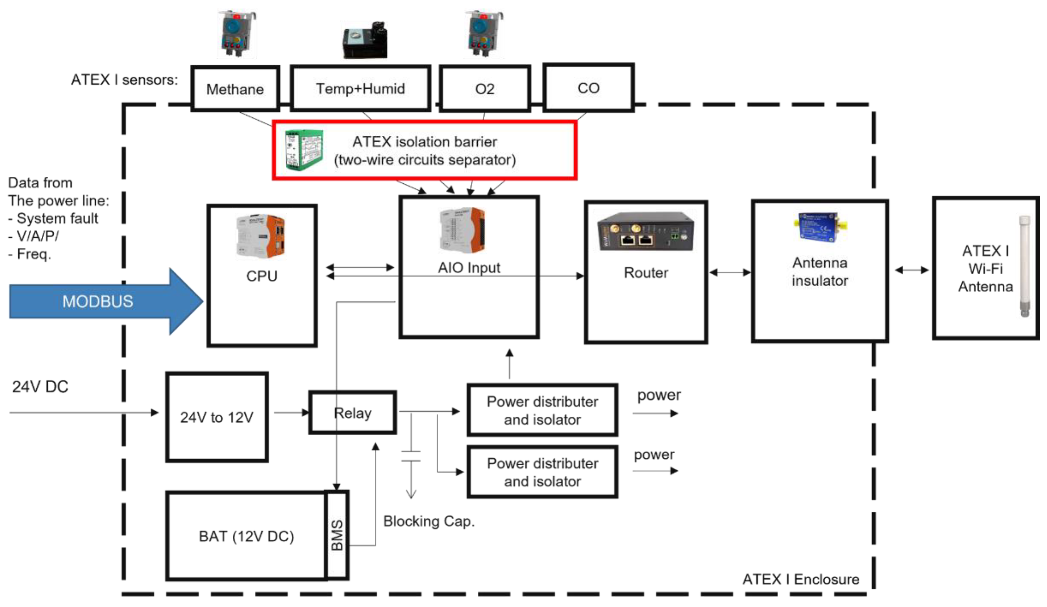
The block diagram in Figure 9 outlines the components included in each access point. All components are placed in an ATEX-certified enclosure. Since the temperature, humidity, methane, oxygen, and carbon monoxide sensors are mounted outside the enclosure, they must also be separately ATEX M1 (mining)-certified. According to the ATEX directives, the signal must pass an ATEX isolation barrier before it is fed to subsequent systems. This ATEX isolation barrier limits the electrical power of the complete line to a safe level. In case of failure, the ATEX isolation barrier takes necessary safety precautions to prevent an explosion. Almost all of the sensors used in this application are analog and, therefore, require further processing. The data arriving from the wide variety of sensors must first be digitized by an analog input/output (I/O) device, and then passed to the onboard industrial controller. The onboard industrial controller is responsible for all data pre-processing and communication operations.

Figure 9.
Conceptual block diagram of the access point developed for the monitoring system within the HEET II project, showing the subparts and how they are connected. The CPU collects data from sensors via an analog input–output (AIO) module, and from the energy transmission system via a Modbus interface, and transmits the aggregated data through mesh-capable Wi-Fi routers. The routers create a seamless single wireless network along the suspended rail track for the tractor module to connect to.
The system also contains external wired communication interfaces, such as Modbus—a de facto standard for industrial electronic devices. The Modbus interface can be used to communicate with the power system. Currently it is not planned to collect data from the wireless receivers (WET5) powering the access points. The system can also operate in the absence of a power supply, as the enclosure houses an onboard 12 V DC battery. This battery is charged whenever the system is connected to the power supply.
4.2. Monitoring the Suspended Tractor
The suspended tractor monitoring module collects data on the tractor status and the battery system, and wirelessly transmits them to the access points; it is connected to the internal tractor system via the controller area network (CAN bus)—a common communication protocol for digital vehicle systems. The collected data can be divided into two groups: status information (binary), and measurement values (analog, converted into the digital domain).
Status information includes the following:
- The status of the control relays;
- The operating state of the drive inverter;
- The presence of the voltage supplying the built-in battery charger;
- Notification of various types of errors via the battery management system (BMS);
- Activation of current leakage protections.
Mean and peak values will be determined for the measured parameters within the given time window; these include the following:
- Battery current;
- Total voltage of the battery;
- The lowest and highest voltages present in individual cells;
- The battery’s state of charge;
- Battery temperature.
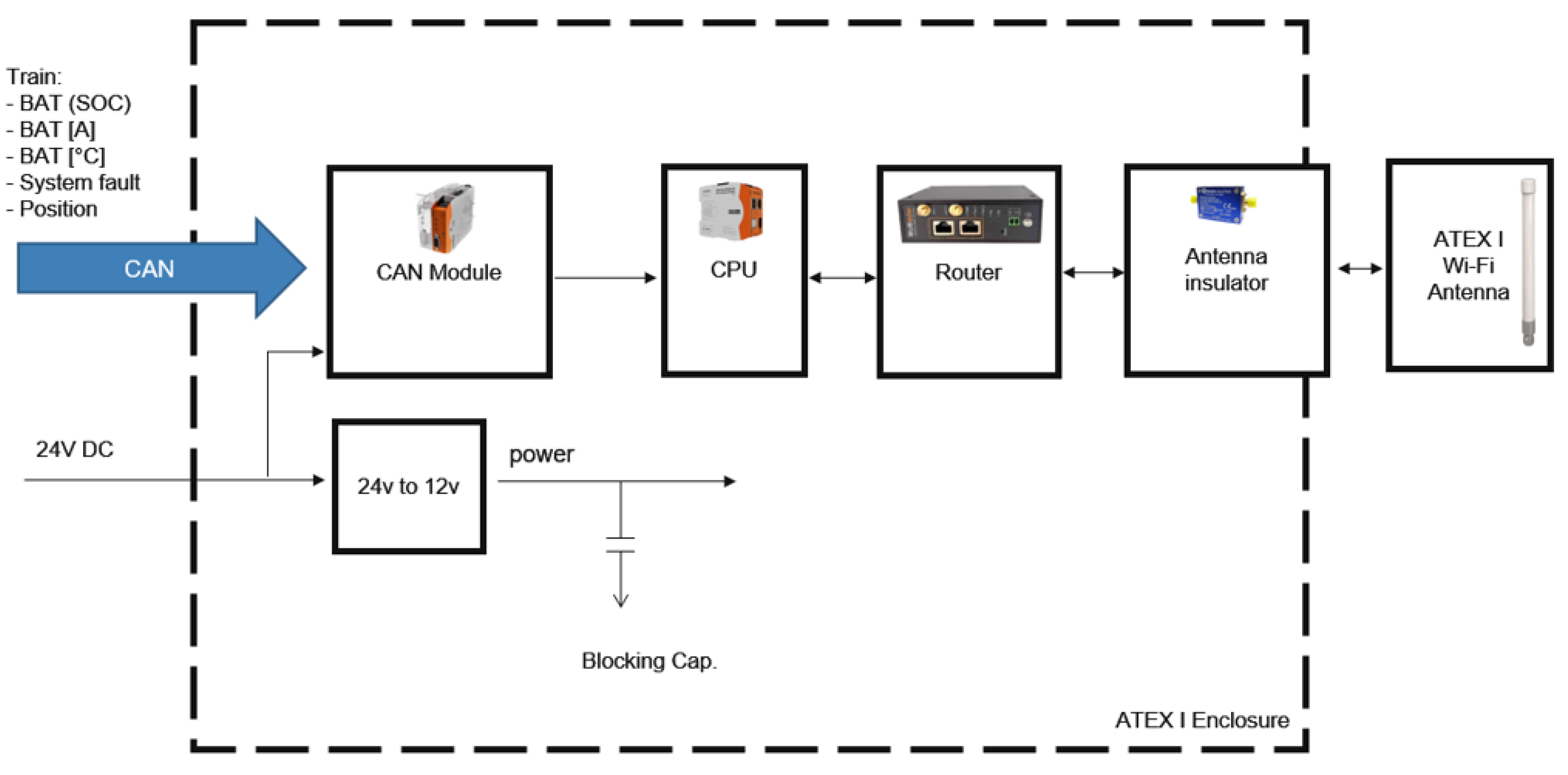
A block diagram of the suspended tractor monitoring module is shown in Figure 10. Similarly to the access points, everything is enclosed in an ATEX-certified enclosure with an ATEX-certified Wi-Fi antenna.
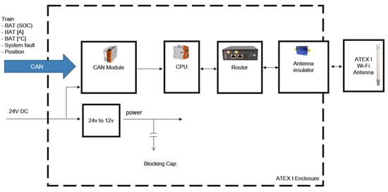
Figure 10.
Conceptual block diagram of the monitoring module of the suspended tractor developed within the HEET II project. The CPU collects data from the power system of the suspended tractor via a CAN interface, and transmits them via the network created by the access points.
4.3. Gateway
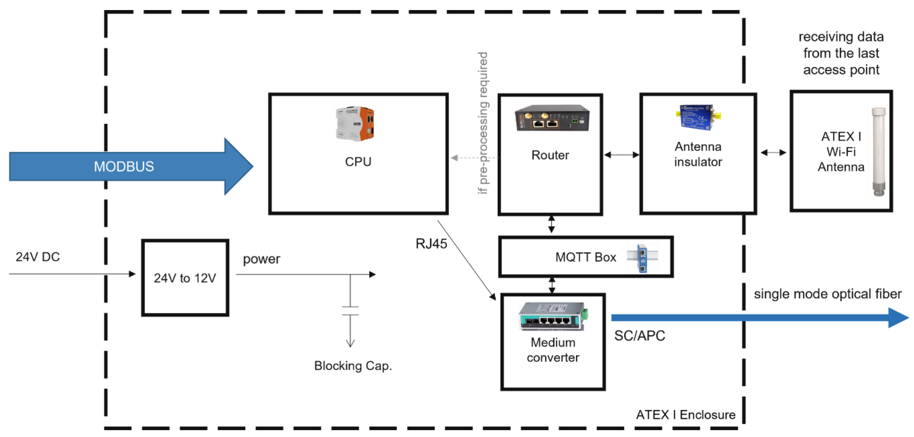
The gateway acts as the main connection to the surface database server; it wirelessly receives the data from the suspended tractor monitoring module and the access points; additionally, it is connected to the single-wire energy receiver SWET2 and the wireless energy transmitter WET3 using the Modbus protocol, and forwards their data. It is connected to the surface database server via a single-mode optical fiber. A block diagram of the gateway is shown in Figure 11. Similarly to the access points, everything is enclosed in an ATEX-certified enclosure with an ATEX-certified Wi-Fi antenna
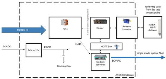
Figure 11.
Conceptual block diagram of the gateway developed within the HEET II project. The gateway aggregates data from the access points via the Wi-Fi network, and transmits them to the surface headquarters’ central database through an optical fiber link.
5. Conclusions
Mining operations always strive for increased productivity and higher safety standards for miners and machines. This paper focuses on the issues related to the monitoring of the energy transmission network and environmental parameters in underground mines, along with an innovative power supply system. This system consists of two subsystems: a single-wire system (SWET), and a wireless system (WET). The latter is intended as a system enabling the batteries to be recharged during movement of the suspended monorail train. It is possible to collect data on the operation of the above-mentioned power supply systems and the monorail in order to analyze them and assess their operational parameters (e.g., power, efficiency, location of the tractor in the roadway).
A monitoring system will collect this data and additionally monitor the state of the energy transmission network and the environmental parameters of the mine. Of particular interest is the presence of hazardous gases, such as methane and carbon monoxide, which pose a significant threat to miner safety. Because of the presence of methane, the whole monitoring system is designed in an explosion-safe manner, aiming for ATEX certification.
The collected data will be transmitted to surface headquarters, where they are stored in a central database. There, the data can be further processed, providing insight into mine operations for potential optimization, and enabling the mine operators to detect and react to hazards before they cause any harm.
Author Contributions
Conceptualization, A.E.K., M.S. (Mrityunjaya Sherikar), and M.S. (Marcin Skora); methodology, A.E.K.; hardware, A.E.K., A.G., M.S. (Mrityunjaya Sherikar), and M.S. (Marcin Skora); validation, A.E.K.; formal analysis, A.E.K.; investigation, A.E.K., M.S. (Mrityunjaya Sherikar), and M.S. (Marcin Skora); writing—original draft preparation, A.E.K., A.G., M.S. (Mrityunjaya Sherikar), and M.S. (Marcin Skora); writing—review and editing, R.M. and K.S.; visualization, A.E.K.; supervision, R.M. and E.C.; project administration, R.M. All authors have read and agreed to the published version of the manuscript.
Funding
This scientific paper was published as part of an international project co-financed by the European Commission Research Fund for Coal and Steel (RFCS) in the years 2020–2023; grant agreement no. 899469. This scientific paper was also published as part of an international project co-financed by the Ministry of Science and Higher Education’s program “PMW” in the years 2020–2023; contract no. 5117/FBWiS/2020/2.

Institutional Review Board Statement
Not applicable.
Informed Consent Statement
Not applicable.
Data Availability Statement
Not applicable.
Acknowledgments
The authors gratefully acknowledge the HEETII project partners for their cooperation in this project.
Conflicts of Interest
The authors declare no conflict of interest.
References
- Pieczora, E.D.; Tokarczyk, J.A. Development of mine underground transportation with use of suspended monorails. Min.–Inform. Autom. Electr. Eng. 2017, 55, 96. [Google Scholar] [CrossRef]
- Matsui, K. Underground Mining Transportation Systems 1. Introduction 2. from Surface to Underground/Vice Versa 2.1. Shafts 2.1.1. Cage 2.1.2. Skips 2.2. Inclined Shafts or Inclined Drifts 3. Underground Transport for Materials and Equipment 3.1. Track System/rail-mounted Systems 3.2. Trackless Systems 3.3. Com. Available online: https://www.semanticscholar.org/paper/Underground-Mining-Transportation-Systems-1.-2.-to-Matsui/67346cf3237e711903becd10b9d0fd29af5ae8b9 (accessed on 24 November 2021).
- Kras, B.; Polnik, B.; Konsek, R. Suspended battery drivetrain as an example of advanced control and safety system of li-ion battery pack technology in mining industry. In Proceedings of the 2013 World Electric Vehicle Symposium and Exhibition (EVS27), Barcelona, Spain, 17–20 November 2013; pp. 1–8. [Google Scholar]
- Zhang, Z.; Pang, H.; Georgiadis, A.; Cecati, C. Wireless Power Transfer—An Overview. IEEE Trans. Ind. Electron. 2019, 66, 1044–1058. [Google Scholar] [CrossRef]
- Włochy Będą Miały Ładującą Indukcyjnie Autostradę. Na Razie Pilotaż, Pierścień o Długości 1050 Metrów (Italy Will Have an Inductively Charging Motorway. for Now a Pilot, a Ring of 1050 Metres). Available online: https://elektrowoz.pl/transport/wlochy-beda-mialy-ladujaca-indukcyjnie-autostrade-na-razie-pilotaz-pierscien-o-dlugosci-1-050-metrow/ (accessed on 24 November 2021).
- Indukcyjna Droga dla Samochodów Elektrycznych. Auto Naładuje się Podczas Jazdy (an Inductive Route for Electric Cars. The Car Will Charge Itself while Driving). Available online: https://moto.pl/MotoPL/7,170318,24921776,indukcyjna-droga-dla-samochodow-elektrycznych-auto-naladuje.html (accessed on 24 November 2021).
- Regensburger, B.; Sinha, S.; Kumar, A.; Vance, J.; Popovic, Z.; Afridi, K.K. Kilowatt-scale large air-gap multi-modular capacitive wireless power transfer system for electric vehicle charging. In Proceedings of the 2018 IEEE Applied Power Electronics Conference and Exposition (APEC), San Antonio, TX, USA, 4–8 March 2018; pp. 666–671. [Google Scholar]
- Zhang, H.; Zhu, C.; Lu, F. Long-Distance and High-Power Capacitive Power Transfer based on the Double-Sided LC Compensation: Analysis and Design. In Proceedings of the 2019 IEEE Transportation Electrification Conference and Expo (ITEC), Detroit, MI, USA, 19–21 June 2019; pp. 1–5. [Google Scholar]
- Kracek, J.; Svanda, M. Analysis of Capacitive Wireless Power Transfer. IEEE Access 2019, 7, 26678–26683. [Google Scholar] [CrossRef]
- Konsek, R. Nowoczesny napęd akumulatorowy ciągnika PCA-1 jako alternatywa dla obecnie stosowanych napędów w ciągnikach transportowych (Modern battery-driven PCA-1 tractor as an alternative to the drives currently used in transport tractors). Zeszyty Problemowe-Maszyny Elektryczne 2012, 2, 1–5. [Google Scholar]
- Mandeno, L. Rural power supply, especially in back country areas. Proc. N. Z. Inst. Eng. 1947, 33, 234–271. [Google Scholar]
- Nkom, B.; Taylor, A.P.R.; Baguley, C. Narrowband Modeling of Single-Wire Earth Return Distribution Lines. IEEE Trans. Power Deliv. 2018, 33, 1565–1575. [Google Scholar] [CrossRef]
- Song, R.; Lu, S.; Sirojan, T.; Phung, B.T.; Ambikairajah, E. Power quality monitoring of single-wire-earth-return distribution feeders. In Proceedings of the 2017 International Conference on High Voltage Engineering and Power Systems (ICHVEPS), Denpasar, Bali, 2–5 October 2017; pp. 404–409. [Google Scholar]
- SWER still Going Strong. Available online: https://esdnews.com.au/swer-still-going-strong/ (accessed on 24 November 2021).
- Zygmanowski, M.; Kasprzak, M.; Kierepka, K.; Michalak, J.; Jarek, G.; Przybyła, K. Power Loss Analysis of Multi-converter System with Single Wire and Wireless Energy Trasfer. In Proceedings of the 2021 International Conference on Electrical Drives & Power Electronics (EDPE), Dubrovnik, Croatia, 22–24 September 2021; pp. 206–211. [Google Scholar]
- Deja, P.; Skóra, M.; Stankiewicz, K.; Tokarczyk, J.; Kasprzak, M.; Kaczmarczyk, Z.; Hildebrandt, R. Wireless energy transfer system for use in underground mining. Energies 2021, 14. (under review). [Google Scholar]
- Thirumala, V.; Verma, T.; Gupta, S. Injury analysis of mine workers: A case study. In Proceedings of the 2017 IEEE International Conference on Industrial Engineering and Engineering Management (IEEM), Singapore, 10–13 December 2017; pp. 269–273. [Google Scholar]
- Cheng, J. Explosions in Underground Coal Mines; Springer International Publishing: Cham, Switzerland, 2018. [Google Scholar]
- Heriyadi, B.; Salia Zakri, R. Evaluation and Analysis of Needs for Air Ventilation Systems in Underground Coal Mine (Case Study in Underground Coal Mine, Sawahlunto City). J. Phys. Conf. Ser. 2021, 1940, 12077. [Google Scholar] [CrossRef]
- Wang, L.; Cheng, Y.-P.; Liu, H.-Y. An analysis of fatal gas accidents in Chinese coal mines. Saf. Sci. 2014, 62, 107–113. [Google Scholar] [CrossRef]
- Ran, D.; Cheng, J.; Zhang, R.; Wang, Y.; Wu, Y. Damages of Underground Facilities in Coal Mines due to Gas Explosion Shock Waves: An Overview. Shock. Vib. 2021, 2021, 8451241. [Google Scholar] [CrossRef]
- Ziętek, B.; Banasiewicz, A.; Zimroz, R.; Szrek, J.; Gola, S. A Portable Environmental Data-Monitoring System for Air Hazard Evaluation in Deep Underground Mines. Energies 2020, 13, 6331. [Google Scholar] [CrossRef]
- Jo, B.; Khan, R.M.A. An Internet of Things System for Underground Mine Air Quality Pollutant Prediction Based on Azure Machine Learning. Sensors 2018, 18, 930. [Google Scholar] [CrossRef] [PubMed] [Green Version]
- Kumar, A.; Kumar, H.; Pandey, V.N.; Singh, D.; Chaulya, S.K. Gas monitoring and power cut-off system for underground mines. In Proceedings of the 2012 7th IEEE Conference on Industrial Electronics and Applications (ICIEA), Singapore, 18–20 July 2012; pp. 463–466. [Google Scholar]
- Dohare, Y.S.; Maity, T.; Paul, P.S.; Prasad, H. Smart low power wireless sensor network for underground mine environment monitoring. In Proceedings of the 2016 3rd International Conference on Recent Advances in Information Technology (RAIT), Dhanbad, India, 3–5 March 2016; pp. 112–116. [Google Scholar]
- Anas, M.; Haider, S.M.; Sharma, P. Gas Monitoring and Testing in Underground Mines using Wireless Technology. Int. J. Eng. Tech. Res. 2017, 6, 412–416. [Google Scholar] [CrossRef]
- Porselvi, T.; Ganesh, S.; Janaki, B.; Priyadarshini, K. IoT Based Coal Mine Safety and Health Monitoring System using LoRaWAN. In Proceedings of the 2021 3rd International Conference on Signal Processing and Communication (ICPSC), Coimbatore, India, 13–14 May 2021; pp. 49–53. [Google Scholar]
- Behr, C.J.; Kumar, A.; Hancke, G.P. A smart helmet for air quality and hazardous event detection for the mining industry. In Proceedings of the 2016 IEEE International Conference on Industrial Technology (ICIT), Taipei, Taiwan, 14–17 March 2016; pp. 2026–2031. [Google Scholar]
- Charde, A.; Dehankar, B.; Ghaturle, S.; Bende, B.; Kitey, S. A Smart and Secured Helmet for Coal Mining Workers; International Journal for Research in Applied Science and Engineering Technology: Sonipat, India, 2020; Volume 8, pp. 673–675. [Google Scholar]
- Kianfar, A.E.; Uth, F.; Baltes, R.; Clausen, E. Development of a Robust Ultra-Wideband Module for Underground Positioning and Collision Avoidance. Min. Metall. Explor. 2020, 37, 1821–1825. [Google Scholar] [CrossRef]


Publisher’s Note: MDPI stays neutral with regard to jurisdictional claims in published maps and institutional affiliations. |
© 2022 by the authors. Licensee MDPI, Basel, Switzerland. This article is an open access article distributed under the terms and conditions of the Creative Commons Attribution (CC BY) license (https://creativecommons.org/licenses/by/4.0/).