Article

Mathematical Model of Steam Reforming in the Anode Channel of a Molten Carbonate Fuel Cell

Faculty of Power and Aeronautical Engineering, Institute of Heat Engineering, Warsaw University of Technology, 21/25 Nowowiejska Street, 00-665 Warsaw, Poland
*
Authors to whom correspondence should be addressed.
Energies 2022, 15(2), 608; https://doi.org/10.3390/en15020608
Submission received: 30 November 2021 / Revised: 9 January 2022 / Accepted: 12 January 2022 / Published: 15 January 2022
(This article belongs to the Special Issue Computational Thermal, Energy, and Environmental Engineering)

Abstract

:
The paper presents a mathematical model of a molten carbonate fuel cell with a catalyst in the anode channel. The modeled system is fueled by methane. The system includes a model of the steam reforming process occurring in the anode channel of the MCFC fuel cell and the model of the cell itself. A reduced order model was used to describe the operation of the molten carbonate fuel cell, whereas a kinetic model describes the methane steam reforming. The calculations of the reforming were done in Aspen HYSYS software. Four values of the steam-to-carbon ratio (2.0, 2.5, 3.0, and 3.5) were used to analyze the performance of the reforming process. In the first phase, the reaction kinetics model was based on data from the literature.

1. Introduction

The authors of the article have previously conducted work related to modeling the reforming process. A mathematical model of a compact plate fin heat exchanger with catalytic coating was presented in [1]. Four values of the steam-to-carbon ratio (2.0, 2.5, 3.0 and 3.5) were used to analyze the performance of the heat exchanger, which was investigated in a temperature range of 500 to 750 °C. It was found that the relative prediction error of the simulator did not exceed 3.5%.
The next step was to build a reformer that was more integrated with the fuel cell. In the proposed solution, the reformer is placed inside the anode channel.
Zhang et al. [2] view fuel cells as promising devices for electrochemical energy conversion, with their efficiency depending, to a great extent, on the efficiency of the oxygen reduction reaction on the cathode side. Li et al. [3], in a study of conductive two-dimensional M3(C6S3O3)2 monolayers as effective electrocatalysts for the oxygen reduction reaction, emphasize that fuel cells are characterized by high conversion efficiency and low pollution. The authors point out that the development of this technology is hampered by the inherent sluggish kinetics of the oxygen reduction reaction on the cathode side. High temperature fuel cells, i.e., MCFC and SOFC which operate typically in temperatures of over 600 °C, have favorable conditions for the reforming of light hydrocarbons with nickel as a catalyst [4]. McPhail et al. [4] note that carbon deposition and contaminant poisoning should be scrutinized in terms of developing MCFC and SOFC. A study on fabricating MCFCs from recycled electronic scrap and the impact of its resulting impurities on cell performance is reported by Milewski et al. [5]. Fuel cells can be powered by various hydrocarbon compounds, using steam reforming of the fuel to produce hydrogen. There are two types of reforming: internal reforming and external reforming. Since internal reforming occurs directly at the anode, the anode acts as both catalyst and electrode, so the hydrogen is used in the electrochemical reaction of the fuel cell immediately after it is created [6,7,8,9]. The effectiveness of hydrogen production is limited by the geometry of the anode channel and by the concentration and flow speed of gases (steam and hydrocarbon) in the anode channel. External reforming requires an independent steam reformer connected to the installation before the anode channel. The geometry of the reformer can be optimized to boost the efficiency of the reformer, and catalysts made of different materials can be applied [10,11].
Methane is the most commonly selected hydrocarbon for research in high temperature fuel cells [12,13,14,15,16,17,18,19,20,21,22], with more research being conducted on SOFC than MCFC. Other compounds have been analyzed as well, particularly simple alcohols, glycerol and ethylene glycol. Methanol is the simplest alcohol, containing only one carbon element; its reforming occurs at around 200–300 °C, while sufficient steam-to-carbon ratio begins at 2:1 [23], and its effectiveness depends strongly on the temperature and the catalyst applied [24]. Alcohols containing two or more carbon elements are not as easy to decay as methanol. Ethanol requires higher temperatures and steam-to-carbon ratios starting from 650 °C, while efficient steam-to-carbon ratios are above 2.8:1 [25,26,27,28]. Compounds containing more carbon elements, like propanol [29,30,31,32], butanol [33,34,35], glycerol [36,37,38,39,40,41], etc., during steam reforming are broken down to simpler structures (ethanol, methanol, methane, carbon oxide, carbon dioxide), and after that the same processes occur as long as the final form is hydrogen and carbon dioxide.
The main problem during the process of steam reforming is the production of pure carbon (coke), which settles on the surface of the catalyst, lowering its active surface [42,43]. Carbon deposition can be avoided in part by lowering the temperature of the process or increasing the steam-to-carbon ratio [42,44,45].
Most of the research available in the literature concerns the reforming process in separate devices (reformers) or direct reforming in the fuel cell. The reforming process of the catalyst located in the anode channel of the fuel cell has not been described.

2. Theory

2.1. Reforming Model

Chemical reaction speed depends on many factors, such as the catalyst used, temperature, and the leading reactions, among others.
Most chemical reactions can be written as follows:
a A + b B + k K + l L +
where a, b, …, k, l, … are the number of moles of substrates A, B, … and products K, L, … of the reaction.
The general equation of the chemical reaction (1) is described using stoichiometric coefficients a, b, k, l. Substrates and products are marked here with the capital letters A, B, K and L.
The reaction rate r in a specific, constant and closed volume can be represented by Equation (2):
1 a d [ A ] d t = 1 b d [ B ] d t = 1 k d [ K ] d t = 1 l d [ L ] d t
where [i] is the concentration of component i.
r = d [ A ] d t
There is a relationship between the degree of reaction, the partial pressures of the reagents and some fixed factors. Rate equation in the system under consideration involves a mass balance equation and reaction rate. The degree of occurrence for components A and B in the reaction can be described as follows [46]:
r = k · [ A ] a · [ B ] b · [ X ] x
where k is the reaction rate coefficient, [] is the concentrations of reactants, [X] is the catalyst impact, and b, c, x are the coefficients (orders of reaction) considering the type of catalyst, reaction mechanism and its type.
Reaction rate k and temperature are related by the Arrhenius equation:
k = A · e E a B · T
where Ea is the activation energy, and A is the pre-exponential coefficient. The values of these coefficients (A and Ea) depend on the reaction.
The chemical reaction kinetics coefficients used in the Aspen HYSYS program to build the mathematical model of methane steam reforming are shown in Table 1.

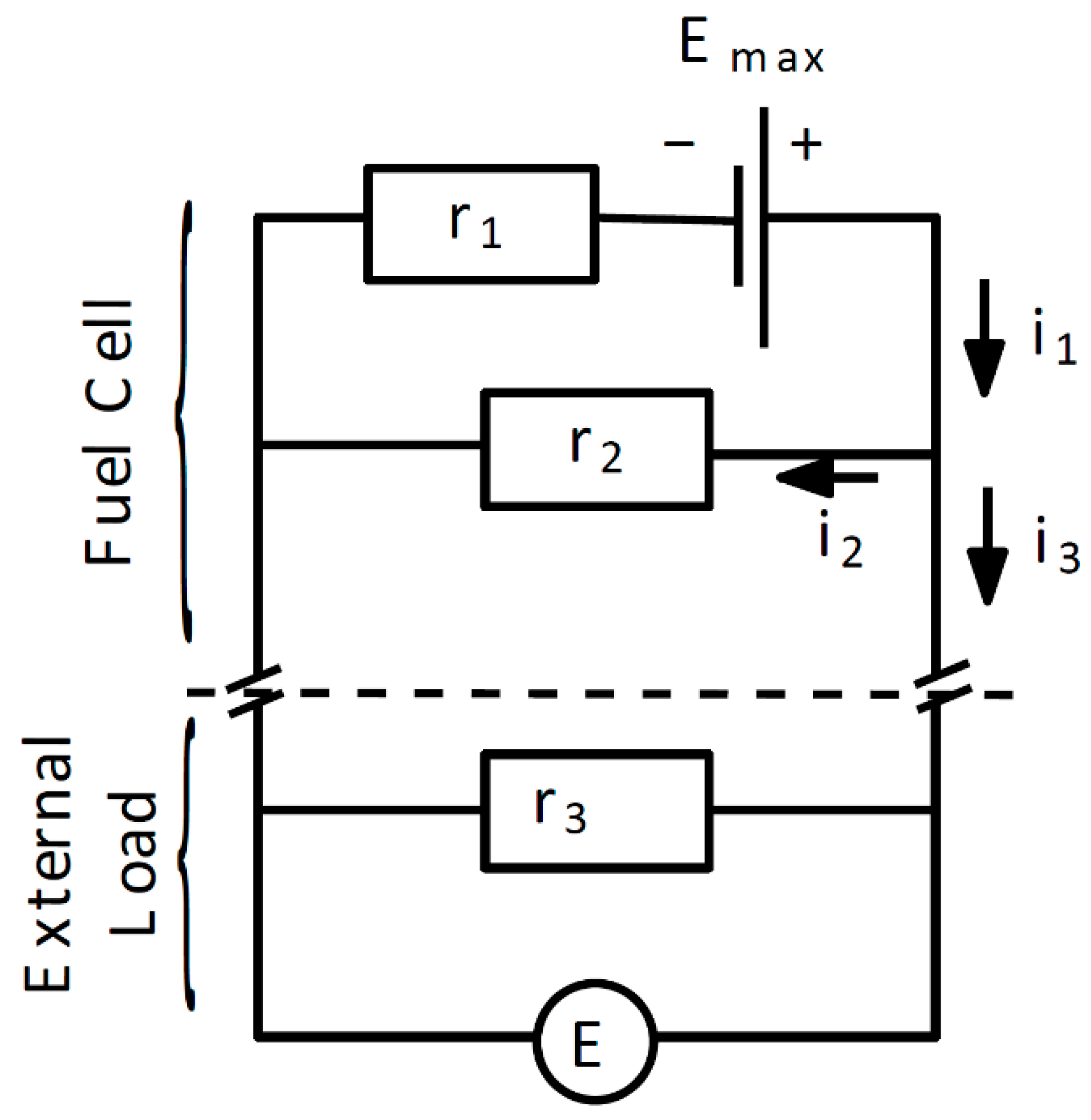
2.2. Fuel Cell Model

The general fuel cell concept is shown in Figure 1. The fuel cell is composed of an anode and a cathode that are separated by an electrolyte. The anode and cathode are made of nickel, whereas the electrolyte is made of lithium carbonate salts, which fill up the porous matrix.
The O2 and CO2 partial pressure difference between cathode and anode causes the ion flow between the cathode and anode. The cathode reaction is as follows:
1 2 O 2 + CO 2 + 2 e CO 3 2
H 2 + CO 3 2 CO 2 + H 2 O + 2 e
Maximum theoretical voltage is defined as Emax, and results from the partial pressure difference of O2 and CO2 between both sides of the fuel cell. The fuel cell electric circuit is simulated as a current source with two resistors (Figure 2). Each fuel cell element (cathode, anode and electrolyte) constitutes electrical resistance, defined as R1. The electrolyte has both electrical and ionic conductivity, which is a disadvantage in this case. Electrons flow in the opposite direction to ions. Ion flow is represented by I2, whereas fuel cell electric resistance is represented by R2. The current source defines maximum fuel cell voltage, whereas the resistors represent fuel cell losses.
Based on Ohm’s law and Kirchoff’s law, fuel cell voltage is defined as follows:
E M C F C = E max η f i max r 1 r 1 r 2 ( 1 η f ) + 1
where Emax is the maximum theoretical voltage, ηf is the fuel utilization factor, imax is the maximum current density, r1 is the specific ionic resistance, and r2 is the specific electric resistance.
Equation (9) uses parameters of current and resistance with reference to the total active area of the fuel cell:
i = I A
r = R · A
where A is the area of the fuel cell.

2.3. Maximum Voltage Emax

The fuel cell produces electricity and heat while remaining at a constant temperature, which makes the process isothermal. In this case, maximum work performed may be described by Equation (11):
L max = M R T ln p i n p o u t
where M is the amount of moles taking part in work performed, and p is partial pressure.
It is necessary to specify the amount of moles taking part in the process and the difference between partial pressure on both sides (cathode and anode stream) before maximum work performed may be determined. In the case of MCFC, work is performed by O2 and CO2 flowing through the cathode side to the anode side. Maximum power generated by the fuel cell depends on the flow of ions through electrolyte, as transported by O2 and CO2 particles. Using Faraday’s law, it is possible to describe the current in the fuel cell with an equation:
I = n M F
where n is the electric load transported by carbonate ions, M is the amount of moles transported in time period, and F is Faraday’s constant.
In the case of the MCFC, a single CO3 = element, during movement from cathode to anode, can carry 4 electrons; thus, the parameter “n” equals 4. Summarizing the above considerations, the Nerst equation compatible for MCFC analysis can be presented thus:
E max = R T 4 F ln p O 2 , c a t h o d e p C O 2 . c a t h o d e 2 p O 2 , a n o d e p C O 2 . a n o d e 2

2.4. Maximum Current Density imax

The maximum current generated by a single cell depends on the amount of fuel and/or oxidizer. Where 100% of the fuel delivered to the fuel cell is utilized, maximum current density is achieved. However, maximum current also depends on the total active area of the fuel cell. The larger the fuel cell area, the bigger the current that can flow. The maximum current is, however, usually given as I/cm2; thus, this value is called current density and described as imax:
i max = 2 F n H 2 , e q u i v a l e n t A
where nH2,equivalent is the defined hydrogen flow.

2.5. Ionic Resistance r1

Ionic resistance is a function of electrolyte thickness and temperature in each layer of the MCFC. It is described with the equation:
r 1 = i l r 1 , a n o d e , i + j m r 1 , e l e c t r o l y t e , j + k n r 1 , c a t h o d e , k
The fuel cell matrix is soaked with electrolyte. The ionic resistance of each layer of the fuel cell can be described with the equation:
r 1 , e l e c t r o l y t e = δ e l e c t r o l y t e σ 1 , e l e c t r o l y t e
where δ is the electrolyte layer thickness, and σ1 is the ionic conductance.
The literature contains various methods for defining the ionic conductance of the electrolyte. For example, Kai Sundmacher et al. [48] suggested the following definition:
σ 1 = 1 β 1 e β 2 T
where β1, β2 are the empirical parameters depending on the material the electrolyte is made of (for example: β1 = 3.34 × 10⁻⁴ S/m; β2 = 1.03 × 10⁴ K).
The carbonates used to produce the electrolyte for the MCFC have a good ionic conductance at high temperature. Although the literature contains no strict dependences between temperature and ionic resistances, there are papers presenting equations for this definition [47,49]. Thus, based on the literature, ionic conductance of the electrolyte can be described by:
σ = σ 0 e E a c t R T
where σ0 (S/cm); Eact (kJ/mol) are the coefficients related to the material of which the electrolyte is made of [47].

2.6. Ionic Resistance r2

In addition to ionic conductivity, MCFC cells are also characterized by electric conductivity. Electric conductivity, as well as air and carbon dioxide leaks, reduce the maximum possible cell voltage. However, the more loaded the cell, the less impact these factors have. Electrical conductivity can be determined from the equations presented above. When the fuel cell does not produce electricity, the fuel utilization factor is equal to zero: ηf = 0, so using Equation (8) we get:
E O C V = E max r 1 r 2 + 1
Electrical resistance can be determined in the same way as ionic resistance:
r 2 = δ σ 2
Using Equations (19) and (20), it is possible to determine the electronic conductivity in the following form:
σ 2 = δ E max E O C V r 1 E O C V
The mathematical model of a fuel cell was built in a spreadsheet using Equations (6)–(21). The mathematical model presented in the article is a combination of two mathematical models. A reduced order model was used to describe molten carbonate fuel cell operation and a kinetic model for methane steam reforming.

3. Experiment

The experimental stand consists of an integrated electronic device equipped with control and regulation elements (thermocouples, thermostats, electric heaters, mass flow regulators, current and voltage measurements and regulators) all controlled by software created in the LabView environment. The experimental stand is connected to the following media: hydrogen, CO2, N2 and compressed air. The additional elements required for the experiments were: methane delivered from a bottle, and water delivered via a peristaltic pump. Water mixed with methane was delivered through the anode channel filled with the catalyst, and was heated to the required temperature by electric heaters, which also kept the temperature of the fuel cell at the required level. CO2 and air were delivered to the cathode channel, and heated to the required temperature. The fuel cell used in the experiments was between the gas delivery manifolds.
Figure 3 shows the cathode, anode, current collectors (anode and cathode), matrix (at the bottom of the figure), gas collectors (cathode on the right, anode on the left) and a catalyst located in the anode channel of the gas collector. Figure 3 also shows gaskets made of vermiculite (elements with the center cut out).
The dimensions of the cathode (and cathode current collector) were 4.5 × 4.5 cm, and the anode (and anode current collector) was 5 × 5 cm, which means the active surface area of the cell was 20.25 cm2 (4.5 × 4.5 cm).
The dimensions of the matrix were 7 × 7 cm. The method of producing this type of matrix is described in [50]. The matrix was impregnated with 5.2 g electrolyte (62%mol Li2CO3 and 38%mol K2CO3).
Then, 2 g of catalyst was placed in the anode channel. Water was fed through a capillary to the anode flow using a peristaltic pump.
The anode current collector and catalyst after operation in a methane-fueled MCFC are shown in Figure 4.

4. Results and Discussion

The results of experimental examination of an MCFC fueled by pure hydrogen are shown in Figure 5. In addition, Figure 5 presents the prediction of our model with respect to experimental data and shows good accordance with it.
The results revealed that the fuel cell used for testing was relatively poor, but all fuel cells used for testing were manufactured in the same way. This enabled us to accurately investigate and define the impact of the reforming process itself on the catalyst located in the anode channel.
Figure 6 and Figure 7 show the current–voltage curves of fuel cells operating on methane at temperatures of 550 °C and 650 °C, respectively. Both experiments (Figure 6 and Figure 7) were performed for various S/C, i.e., 2, 2.5, 3 and 3.5. The discrepancy between the simulation results and experimental data was slightly bigger for the data presented in Figure 5, but it can still be assumed that the model can predict fuel cell performance during operation with methane.
The research demonstrated that fuel cell performance is highly dependent on operating temperature, although the relationship between fuel cell performance and the S/C ratio was less evident. This can be seen especially in Figure 8, where the maximum powers achieved by the cell were compared at different S/C ratios, and at two different temperatures. The reason behind this was that a relatively high flow of methane, with respect to fuel cell active area, i.e., 20.25 cm2 was supplied with 3 Nl/h of methane. Only one exception was observed during fuel cell testing at temperature 650 °C, with S/C = 2, where fuel cell performance was clearly registered.
When the fuel cell was operating at 550 °C, the best fuel cell performance was observed with S/C equal to 3.0. However, it has to be highlighted that the difference in performance was not significantly larger with respect to the test results of the other S/C. Clearly, at this temperature, the steam reforming process takes place less efficiently, resulting in lower fuel cell performance. In the experiments performed at 650 °C, the highest power achieved by the fuel cell was at the 2.5 S/C ratio. The fuel cell achieved better power results at all other S/C ratio experiments at higher temperatures (Figure 8).
Most of the reported research focuses on the performance of the reforming reaction, while comparative fuel cell power density is not deeply discussed. Dicks [7] states the operating temperature of MCFC is high enough for the steam reforming reaction inside the stack. The author carried out laboratory testing to characterize the catalytic steam reforming. The research was oriented at examination of the methane conversion rate as a function of time, whereas the performance of MCFC was not discussed.
Clarke et al. [6] examined the steam reforming of hydrocarbon in internal reforming MCFC. The authors reported the performance of three types of DIR-MCFC catalyst. They reported that the OCV for a non-reforming cell was bigger by 0.4 V than for DIR-MCFC. The voltage corresponding to current density 150 mA/cm2 did not differ.
The comparison of MCFC performance operating with different anodic gas composition was reported by Bove and Lunghi [12]. The authors examined single cell MCFC operating with natural gas and various types of biogas. The tests revealed the performance of MCFC with biogas is very close to MCFC with natural gas—the maximum power density varies ca. 15%.
Our study concentrated mainly on MCFC performance as a function of operating temperature and S/C ratio. The results were compared with results obtained for pure hydrogen as a reference.

5. Conclusions

A mathematical model was built of the MCFC cell and methane reformer inside the MCFC anode channel. This article combines two models: reduced order model for molten carbonate fuel cell operation and the kinetic model for methane steam reforming. The model was then validated and calibrated based on the data from experiments. It was noticeable that the materials used to construct the cells were characterized by quite low performance, but all the tests shown were for the same materials, so the impact of the reforming process itself for the catalyst located in the anode channel can be seen. Temperature had a huge impact on fuel cell performance. The results of the experiments showed that fuel cell performance was about 30% worse when the temperature was reduced from 650 °C to 550 °C. It was noticeable that the steam-to-carbon ratio of 2.0 was too low for methane fuel with the current catalyst applied, whereas S/C ratios of 2.5 and higher delivered better fuel cell performance results.

Author Contributions

Conceptualization, L.S. and J.M.; methodology, L.S., O.D., A.S. and J.M.; software, L.S.; validation, L.S. and O.D.; formal analysis, L.S. and O.D.; investigation, L.S. and O.D.; resources, L.S., O.D., A.S. and J.M.; data curation, L.S. and O.D.; writing—original draft preparation, L.S., O.D. and A.S.; writing—review and editing, L.S., O.D., A.S. and J.M.; visualization, L.S. and O.D.; supervision, L.S.; project administration, L.S.; funding acquisition, L.S. All authors have read and agreed to the published version of the manuscript.

Funding

National Science Center, Poland (Grant number 2020/39/D/ST8/02021).

Institutional Review Board Statement

Not applicable.

Informed Consent Statement

Not applicable.

Data Availability Statement

The data presented in this study are available on request from the corresponding author.

Acknowledgments

This research was funded in part by the National Science Center, Poland (Grant number 2020/39/D/ST8/02021). For the purpose of Open Access, the author has applied a CC-BY public copyright license to any Author Accepted Manuscript (AAM) version arising from this submission.

Conflicts of Interest

The authors declare no conflict of interest.

References

  1. Szablowski, L.; Kupecki, J.; Milewski, J.; Motylinski, K. Kinetic model of a plate fin heat exchanger with catalytic coating as a steam reformer of methane, biogas, and dimethyl ether. Int. J. Energy Res. 2019, 43, 2930–2939. [Google Scholar] [CrossRef]
  2. Zhang, J.; Zhou, Z.; Wang, F.; Li, Y.; Jing, Y. Two-Dimensional Metal Hexahydroxybenzene Frameworks as Promising Electrocatalysts for an Oxygen Reduction Reaction. ACS Sustain. Chem. Eng. 2020, 8, 7472–7479. [Google Scholar] [CrossRef]
  3. Li, T.; Li, M.; Zhu, X.; Zhang, J.; Jing, Y. Conductive two-dimensional M3 (C6S3O3)2 monolayers as effective electrocatalysts for the oxygen reduction reaction. J. Mater. Chem. A 2021, 9, 24887–24894. [Google Scholar] [CrossRef]
  4. McPhail, S.J.; Aarva, A.; Devianto, H.; Bove, R.; Moreno, A. SOFC and MCFC: Commonalities and opportunities for integrated research. Int. J. Hydrog. Energy 2011, 36, 10337–10345. [Google Scholar] [CrossRef]
  5. Milewski, J.; Cwieka, K.; Szczęśniak, A.; Szabłowski, Ł.; Wejrzanowski, T.; Skibinski, J.; Dybiński, O.; Lysik, A.; Sienko, A.; Stanger, P. Recycling electronic scrap to make molten carbonate fuel cell cathodes. Int. J. Hydrog. Energy 2021. [Google Scholar] [CrossRef]
  6. Clarke, S.H.; Dicks, A.L.; Pointon, K.; Smith, T.A.; Swann, A. Catalytic aspects of the steam reforming of hydrocarbons in internal reforming fuel cells. Catal. Today 1997, 38, 411–423. [Google Scholar] [CrossRef]
  7. Dicks, A.L. Advances in catalysts for internal reforming in high temperature fuel cells. J. Power Sources 1998, 71, 111–122. [Google Scholar] [CrossRef]
  8. Freni, S.; Maggio, G. Energy balance of different internal reforming MCFC configurations. Int. J. Energy Res. 1997, 21, 164–170. [Google Scholar] [CrossRef]
  9. Heidebrecht, P.; Sundmacher, K. Molten carbonate fuel cell (MCFC) with internal reforming: Model-based analysis of cell dynamics. Chem. Eng. Sci. 2003, 58, 1029–1036. [Google Scholar] [CrossRef]
  10. Campanari, S.; Manzolini, G.; Chiesa, P. Using MCFC for high efficiency CO2 capture from natural gas combined cycles: Comparison of internal and external reforming. Appl. Energy 2013, 112, 772–783. [Google Scholar] [CrossRef]
  11. Musa, A.; Steeman, H.J.; De Paepe, M. Performance of internal and external reforming molten carbonate fuel cell systems. J. Fuel Cell Sci. Technol. 2007, 4, 65–71. [Google Scholar] [CrossRef]
  12. Bove, R.; Lunghi, P. Experimental comparison of MCFC performance using three different biogas types and methane. J. Power Sources 2005, 145, 588–593. [Google Scholar] [CrossRef]
  13. Guerra, C.; Lanzini, A.; Leone, P.; Santarelli, M.; Brandon, N.P. Optimization of dry reforming of methane over Ni/YSZ anodes for solid oxide fuel cells. J. Power Sources 2014, 245, 154–163. [Google Scholar] [CrossRef]
  14. Klein, J.M.; Hénault, M.; Roux, C.; Bultel, Y.; Georges, S. Direct methane solid oxide fuel cell working by gradual internal steam reforming: Analysis of operation. J. Power Sources 2009, 193, 331–337. [Google Scholar] [CrossRef]
  15. Lanzini, A.; Leone, P.; Guerra, C.; Smeacetto, F.; Brandon, N.P.; Santarelli, M. Durability of anode supported Solid Oxides Fuel Cells (SOFC) under direct dry-reforming of methane. Chem. Eng. J. 2013, 220, 254–263. [Google Scholar] [CrossRef]
  16. Lin, Y.; Zhan, Z.; Liu, J.; Barnett, S.A. Direct operation of solid oxide fuel cells with methane fuel. Solid State Ion. 2005, 176, 1827–1835. [Google Scholar] [CrossRef]
  17. Lin, Y.; Zhan, Z.; Barnett, S.A. Improving the stability of direct-methane solid oxide fuel cells using anode barrier layers. J. Power Sources 2006, 158, 1313–1316. [Google Scholar] [CrossRef]
  18. Liu, J.; Barnett, S.A. Operation of anode-supported solid oxide fuel cells on methane and natural gas. Solid State Ion. 2003, 158, 11–16. [Google Scholar] [CrossRef]
  19. Ni, M. Electrolytic effect in solid oxide fuel cells running on steam/methane mixture. J. Power Sources 2011, 196, 2027–2036. [Google Scholar] [CrossRef] [Green Version]
  20. Ni, M. Modeling and parametric simulations of solid oxide fuel cells with methane carbon dioxide reforming. Energy Convers. Manag. 2013, 70, 116–129. [Google Scholar] [CrossRef] [Green Version]
  21. Pillai, M.; Lin, Y.; Zhu, H.; Kee, R.J.; Barnett, S.A. Stability and coking of direct-methane solid oxide fuel cells: Effect of CO2 and air additions. J. Power Sources 2010, 195, 271–279. [Google Scholar] [CrossRef]
  22. Wang, W.; Zhou, W.; Ran, R.; Cai, R.; Shao, Z. Methane-fueled SOFC with traditional nickel-based anode by applying Ni/Al2O3 as a dual-functional layer. Electrochem. Commun. 2009, 11, 194–197. [Google Scholar] [CrossRef]
  23. Sá, S.; Silva, H.; Brandão, L.; Sousa, J.M.; Mendes, A. Catalysts for methanol steam reforming-A review. Appl. Catal. B Environ. 2010, 99, 43–57. [Google Scholar] [CrossRef]
  24. Yaakob, Z.; Kamarudin, S.K.; Daud, W.R.W.; Yosfiah, M.R.; Lim, K.L.; Kazemian, H. Hydrogen production by methanol-steam reforming using Ni-Mo-Cu/γ- alumina trimetallic catalysts. Asia-Pac. J. Chem. Eng. 2010, 5, 862–868. [Google Scholar] [CrossRef]
  25. Douvartzides, S.L.; Coutelieris, F.A.; Demin, A.K.; Tsiakaras, P.E. Electricity from ethanol fed SOFCs: The expectations for sustainable development and technological benefits. Int. J. Hydrog. Energy 2004, 29, 375–379. [Google Scholar] [CrossRef]
  26. Alberton, A.L.; Souza, M.M.V.M.; Schmal, M. Carbon formation and its influence on ethanol steam reforming over Ni/Al2O3 catalysts. Catal. Today 2007, 123, 257–264. [Google Scholar] [CrossRef]
  27. Vizcaíno, A.J.; Carrero, A.; Calles, J.A. Hydrogen production by ethanol steam reforming over Cu-Ni supported catalysts. Int. J. Hydrog. Energy 2007, 32, 1450–1461. [Google Scholar] [CrossRef]
  28. Comas, J.; Marino, F.; Laborde, M.; Amadeo, N. Bio-ethanol steam reforming on Ni/Al2O3 catalyst. Chem. Eng. J. 2004, 98, 61–68. [Google Scholar] [CrossRef]
  29. Resini, C.; Arrighi, L.; Delgado, M.C.H.; Vargas, M.A.L.; Alemany, L.J.; Riani, P.; Berardinelli, S.; Marazza, R.; Busca, G. Production of hydrogen by steam reforming of C3 organics over Pd-Cu/γ-Al2O3 catalyst. Int. J. Hydrog. Energy 2006, 31, 13–19. [Google Scholar] [CrossRef]
  30. Myint, M.; Yan, Y.; Chen, J.G. Reaction pathways of propanal and 1-propanol on fe/ni(111) and cu/ni(111) bimetallic surfaces. J. Phys. Chem. C 2014, 118, 11340–11349. [Google Scholar] [CrossRef]
  31. Mizuno, T.; Matsumura, Y.; Nakajima, T.; Mishima, S. Effect of support on catalytic properties of Rh catalysts for steam reforming of 2-propanol. Int. J. Hydrog. Energy 2003, 28, 1393–1399. [Google Scholar] [CrossRef]
  32. Wang, M.; Au, C.T.; Lai, S.Y. H2 production from catalytic steam reforming of n-propanol over ruthenium and ruthenium-nickel bimetallic catalysts supported on ceria-alumina oxides with different ceria loadings. Int. J. Hydrog. Energy 2015, 40, 13926–13935. [Google Scholar] [CrossRef]
  33. Yadav, A.K.; Vaidya, P.D. Reaction Kinetics of Steam Reforming of n-Butanol over a Ni/Hydrotalcite Catalyst. Chem. Eng. Technol. 2018, 41, 890–896. [Google Scholar] [CrossRef]
  34. Patel, R.; Patel, S. Renewable hydrogen production from butanol: A review. Clean Energy 2017, 1, 90–101. [Google Scholar] [CrossRef]
  35. Nahar, G.A.; Madhani, S.S. Thermodynamics of hydrogen production by the steam reforming of butanol: Analysis of inorganic gases and light hydrocarbons. Int. J. Hydrog. Energy 2010, 35, 98–109. [Google Scholar] [CrossRef]
  36. Schwengber, C.A.; Alves, H.J.; Schaffner, R.A.; Da Silva, F.A.; Sequinel, R.; Bach, V.R.; Ferracin, R.J. Overview of glycerol reforming for hydrogen production. Renew. Sustain. Energy Rev. 2016, 58, 259–266. [Google Scholar] [CrossRef]
  37. Dou, B.; Dupont, V.; Rickett, G.; Blakeman, N.; Williams, P.T.; Chen, H.; Ding, Y.; Ghadiri, M. Hydrogen production by sorption-enhanced steam reforming of glycerol. Bioresour. Technol. 2009, 100, 3540–3547. [Google Scholar] [CrossRef] [Green Version]
  38. Dou, B.; Wang, C.; Song, Y.; Chen, H.; Xu, Y. Activity of Ni-Cu-Al based catalyst for renewable hydrogen production from steam reforming of glycerol. Energy Convers. Manag. 2014, 78, 253–259. [Google Scholar] [CrossRef]
  39. Sánchez, E.A.; D’Angelo, M.A.; Comelli, R.A. Hydrogen production from glycerol on Ni/Al2O3 catalyst. Int. J. Hydrog. Energy 2010, 35, 5902–5907. [Google Scholar] [CrossRef]
  40. Adhikari, S.; Fernando, S.D.; Haryanto, A. Hydrogen production from glycerol: An update. Energy Convers. Manag. 2009, 50, 2600–2604. [Google Scholar] [CrossRef]
  41. Cheng, C.K.; Foo, S.Y.; Adesina, A.A. Glycerol steam reforming over bimetallic Co-Ni/Al2O3. Ind. Eng. Chem. Res. 2010, 49, 10804–10817. [Google Scholar] [CrossRef]
  42. Lytkina, A.A.; Zhilyaeva, N.A.; Ermilova, M.M.; Orekhova, N.V.; Yaroslavtsev, A.B. Influence of the support structure and composition of Ni-Cu-based catalysts on hydrogen production by methanol steam reforming. Int. J. Hydrog. Energy 2015, 40, 9677–9684. [Google Scholar] [CrossRef]
  43. Pomfret, M.B.; Steinhurst, D.A.; Owrutsky, J.C. Methanol and ethanol fuels in solid oxide fuel cells: A thermal imaging study of carbon deposition. Energy Fuels 2011, 25, 2633–2642. [Google Scholar] [CrossRef]
  44. Laosiripojana, N.; Assabumrungrat, S. Catalytic steam reforming of methane, methanol, and ethanol over Ni/YSZ: The possible use of these fuels in internal reforming SOFC. J. Power Sources 2007, 163, 943–951. [Google Scholar] [CrossRef]
  45. Lwin, Y.; Daud, W.R.W.; Mohamad, A.B.; Yaakob, Z. Hydrogen production from steam-methanol reforming: Thermodynamic analysis. Int. J. Hydrog. Energy 2000, 25, 47–53. [Google Scholar] [CrossRef]
  46. Young, D.C. Computational Chemistry: A Practical Guide for Applying Techniques to Real World Problems; Wiley: New York, NY, USA, 2001. [Google Scholar]
  47. Milewski, J.; Wołowicz, M.; Miller, A.; Bernat, R. A reduced order model of molten carbonate fuel cell: A proposal. Int. J. Hydrog. Energy 2013, 38, 11565–11575. [Google Scholar] [CrossRef]
  48. Sundmacher, K.; Kienle, A.; Pesch, H.J.; Berndt, J.F.; Huppmann, G. Molten Carbonate Fuel Cells: Modeling, Analysis, Simulation, and Control; Wiley-VCH Verlag GmbH & Co. KGaA: Weinheim, Germany, 2007. [Google Scholar]
  49. Morita, H.; Komoda, M.; Mugikura, Y.; Izaki, Y.; Watanabe, T.; Masuda, Y.; Matsuyama, T. Performance analysis of molten carbonate fuel cell using a Li/Na electrolyte. J. Power Sources 2002, 112, 509–518. [Google Scholar] [CrossRef]
  50. Baron, R.; Wejrzanowski, T.; Milewski, J.; Szabłowski, Ł.; Szczęśniak, A.; Fung, K.Z. Manufacturing of Γ-LiAlO2 matrix for molten carbonate fuel cell by high-energy milling. Int. J. Hydrog. Energy 2018, 43, 6696–6700. [Google Scholar] [CrossRef]
Figure 1. Working principle of MCFC.
Energies 15 00608 g001
Figure 2. Modeled electric circuit [47].
Energies 15 00608 g002
Figure 3. Materials for assembling the MCFC with a catalyst in the anode channel.
Energies 15 00608 g003
Figure 4. Anode current collector (bottom) and catalyst (top) after working in a methane-fueled MCFC.
Energies 15 00608 g004
Figure 5. Polarization curves for MCFC fed by hydrogen.
Energies 15 00608 g005
Figure 6. Polarization curves for MCFC fed by methane for 550 °C and S/C = 2, 2.5, 3, 3.5.
Energies 15 00608 g006
Figure 7. Polarization curves for MCFC fed by methane for 650 °C and S/C = 2, 2.5, 3, 3.5.
Energies 15 00608 g007
Figure 8. Comparison of maximum power achieved by the fuel cell during experiments.
Energies 15 00608 g008
Table 1. Kinetics coefficients of chemical reactions used in the mathematical model.
Chemical ReactionAEa, kJ/kmol
CH 4 + H 2 O CO + 3 H 2 1 × 105107,300
CO + H 2 O CO 2 + H 2 1 × 1010114,800
Publisher’s Note: MDPI stays neutral with regard to jurisdictional claims in published maps and institutional affiliations.

