1. Introduction
Due to an ever-increasing demand for efficient carbon-neutral energy technologies, a considerable amount of attention from both the academic and industrial worlds has been directed towards high-temperature electrochemical solid oxide cell (SOC) conversion systems integrated with renewable energy sources for their high energy efficiency combined with a strong reduction in greenhouse gas [
1], along with a nearly total absence of particulate and nitrous oxide gas emission for SOCs, when they are operated in fuel cell mode [
2].
Among the various types of ceramic and metallic materials used for SOC stack and balance-of-plant components, ferritic stainless steel interconnects play a key role in ensuring the stable and efficient performance of stacks operating in the intermediate temperature range of 600–750 °C over prolonged periods of time [
3,
4]. Although the interconnect is exposed to demanding dual-atmosphere conditions consisting of an oxidizing atmosphere on one side and a reducing atmosphere on the opposite side, an acceptable amount of corrosion protection is provided by a dense, compact and slow-growing chromia layer. However, the poor electrical conductivity of the oxidized steel surface and chromia evaporation represents two insidious degradation issues on the oxidizing atmosphere side, causing a progressive and continuous interconnect and cell performance loss over time [
5,
6]. For this reason, the functionalization of the steel surface using a coating deposition of conductive mixed metal oxides prevalently based on spinel Co, Mn-Co or perovskite La-Co phases is usually needed for stabilizing the long-term interconnect performance on the oxidizing side [
7,
8,
9]. Numerous deposition methods have been studied for coating deposition, including chemical vapor deposition, wet chemical, vacuum deposition, thermal spraying and electroplating methods [
10,
11]. Several studies have demonstrated that spinel oxides are highly effective coatings, whereas more controversial results have been reported in the literature regarding the capability of perovskite oxide coatings to provide durable SOC interconnect protection [
10]. The non-protective nature of perovskite oxides appears to be related to an easier transport of chromium and oxygen [
7,
10], which promotes Cr evaporation along with rapid growth of insulating chromia subscales. However, some authors have also observed that stable spinel layers may form spontaneously under La-Co or La-Fe-Ni perovskite coatings by interdiffusion during extended consolidation treatments at high temperatures and that the presence of the spontaneously formed spinel sub-layer is very effective in blocking ion transport across the perovskite coating structure [
12]. Proceeding from these observations, the effect of spinel sublayers on perovskite coating protection has been the object of subsequent and more detailed investigations by a number of authors. Thus, for instance, thin films of combined LaCoO
3 perovskite and spinel Co
3O
4 coatings were prepared via an easy electrochemical route in a La nitrate-containing solution, starting from a Co-coated Crofer 22APU steel substrate [
13,
14]. Thermal conversion at 800 °C in air resulted in the formation of a 1 µm thick LaCoO
3 layer on top of a 2 µm thick Co
3O
4 layer. Metal oxide with a perovskite structure is notoriously difficult to attach to a metal substrate [
15]. However, the spinel sublayer played a key role in obtaining a good adhesion strength of the perovskite layer. The combined spinel/perovskite structure also exhibited a very low electrical resistance, in the range of 700–800 °C. In another study, a dual-layer perovskite La
0.6Sr
0.4CoO
3-NiFe
2O
4 spinel coating, where the NiFeO
4 phase was formed by thermal conversion treatments of metallic NiFe precursion layers, promoted a higher oxidation resistance and Cr diffusion barrier on a 430 ferritic stainless steel interconnect [
16]. Similar beneficial diffusion barrier properties were also reported on steel interconnects protected by a dual-layer Co
3O
4-La
0.85Sr
0.15Mn
3-δ coating, which was prepared by slurry coating, a direct and more conventional method of deposition not requiring thermal conversion routes [
17]. It is important to note that thermal conversion routes are also commonly applied in SOC interconnect coating technology to prepare thin-film spinel Co, Co-Ce and Cu-Fe oxide layers that are currently considered among the top-performing coatings for steel interconnect protection [
18,
19,
20,
21,
22].
In this context, a novel thermo-chemical conversion coating process has been recently developed and applied in our laboratory for producing a perovskite coating consisting of a dual perovskite–spinel layer structure [
23,
24,
25,
26,
27]. The process occurs at approximately 600 °C via immersion in a Li-containing molten carbonate salt bath and produces a pure perovskite LaFeO
3 layer through the reaction of the steel surface with La
2O
3 added to the carbonate bath. In addition, a spinel Fe-Cr intermediate layer forms during the treatment below the perovskite layer. The effects of several process parameters, such as immersion time, temperature and chemistry of the salt bath and the use of chemical accelerants, have been investigated over the past few years in an attempt to control and optimize the thickness, microstructure and functional properties of such perovskite conversion coatings [
27]. Our previous studies have indicated that with this process, a coating thickness ranging from hundreds of nanometers to several microns may be obtained and that there is a strict relationship among thickness, morphology and coating electrical properties. In general, thin-film coatings of around 1 µm thickness characterized by a homogeneous dual-layer structure with an outer thin LaFeO
3 layer and an inner mixed Fe-Cr spinel oxide are obtained using small amounts of nitrates as reaction accelerants [
27]. In nitrate-free baths, however, higher coating thicknesses are obtained along with a structure that gradually passes from a homogeneous to a well-separated layered morphology with LaFeO
3 on the inner spinel oxide, which is in two distinct Fe-rich and Fe-Cr spinel layers [
23,
24,
25,
26]. Due to the semiconducting electrical properties of both undoped LaFeO
3 [
28] and Fe-based spinel layers [
29], the coating thickness is the main contributor to the electrical properties of perovskite coatings, in terms of Area-Specific Resistance (ASR). Consequently, the electrical measurements conducted under typical SOFC interconnect gas environments produced acceptable ASR values using only thin conversion coating films. Thus, for instance, reducing the coating thickness from 10–15 to 1–3 µm resulted in a drop in ASR from nearly 90 to less than 50 mΩ cm
2 for a K41 steel substrate after 1000 h of exposure at 700 °C in air [
25]. Although this value falls below the generally accepted limit of 50 mΩ cm
2, it still remains 4–5 times higher than in benchmark Ce/Co coatings [
21]. These results suggest that further process optimization is needed if more conductive thin-film perovskite coatings are desired. Acceptor dopants, such as divalent alkaline earth metals, are widely used to increase the electrical conductivity of LaFeO
3 perovskite ceramics. Based on energetic and steric considerations, acceptor doping with Ca and Sr is the most suitable method to achieve optimal conductivity effects in the LaFeO
3 lattice by partial replacement on the La site [
30]. Thus, for instance, at 700 °C, electrical conductivity of 20 S/cm has been reported for a doped La
1−xSr
xFeO
3 with x = 0.1, which is 50 times higher than that of undoped LaFeO
3 [
31]. Similar improvements have been obtained with Ca doping [
28].
In order to form conductive Sr- or Ca-doped LaFeO
3 layers during the conversion process, the dopants must be added to the bath in the form of soluble oxide species. A sufficient molten carbonate solubility of Ca or Sr oxide is, therefore, necessary to guarantee their availability and reactivity during the formation process of the perovskite coating. Adequate documentation exists regarding the solubility properties of alkali earth cations in Li-containing molten carbonates, indicating a very limited solubility of CaO [
32], as compared with SrO, which has been found to assimilate comparatively easily up to 5 wt % at 650 °C [
33]. For this reason, the possibility of producing acceptor-doped LaFeO
3 layers has been investigated in this paper using Sr as the most suitable dopant. The ASR electrical properties of thin-film perovskite coatings grown in Sr-free and Sr-added molten carbonate baths have also been measured and compared.
2. Materials and Methods
The experiments in this study were conducted using an 18 Cr commercial K41/441 ferritic stainless steel with the following nominal composition (wt%): Cr 17.8; Ti + Nb 0.65; Si 0.6; Mn 0.3; C 0.015.
Coupons of 20 × 20 mm size cut from a 1 mm thick plate were grounded and then polished with diamond pastes to a 3 µ finish. Thereafter, the polished coupons were degreased with ethanol, rinsed in water and then dried.
The base composition of the salt bath consisted of a binary eutectic Li2CO3-Na2CO3 (53/47 mol%) carbonate mixture containing 1 mol% La2O3 and 0.5 mol% LiNO3. A 3 mol% SrO was added to this base composition to prepare the Sr-containing salt bath (hereafter, the coating grown in this salt will be identified as the S-coating). For comparison purposes, a Sr-free salt bath with similar oxo-basicity was also prepared by adding a 3 mol% MgO to the base composition. Hereafter, this reference coating will be identified as the M-coating.
Preliminary tests were conducted to determine the best conditions for coating formation. The optimal preparation of perovskite-coated coupons was realized by immersing them in the salt bath for 4 h at 580 °C under continuous CO
2 gas bubbling (60 mL/min). The electrochemical cell, experimental procedures and instrumentation used for the coating preparation are described elsewhere [
24]. Subsequently, a gold wire directly immersed in the melt was used as a pseudo-reference electrode, whereas a graphite rod with an electrode area 10 times larger than the steel coupon (working electrode) was used as a counter electrode. The coating formation process was followed by open circuit potential (OCP) and electrochemical impedance spectroscopy (EIS) measurements. In particular, during EIS measurements, the gas feeding was stopped to avoid bubbling interference noise. EIS spectra were acquired at OCP conditions with a 5 mV rms amplitude over a frequency range of 10 kHz to 30 mHz. All the electrochemical measurements were performed using a Solartron SI-1286 Potentiostat/Electrochemical Interface in combination with a Solartron 1260A Frequency Response Analyzer FRA. The electrochemical instrumentation was driven by Corrware/ ZPlot software from Scribner.
The surfaces and cross-sections of the coupons were examined by a Tescan Vega 3 Scanning Electron Microscope equipped with an Energy-Dispersive X-ray detector (SEM/EDX) for microstructure and chemical analysis. An X-ray diffraction (XRD) analysis for phase identification was carried out with a Rigaku SmartLab diffractometer. Prior to analysis, the coupons were thoroughly cleaned with boiling water to remove any possible residual salt layers remaining on the coupon surface. Cross-sections were prepared by cold mounting with Struers EpoFix resin using standard polishing procedures up to a mirror-like finish.
For the electrical characterization, a conventional 2- probe 4-point method was used to measure the ASR of the coated steel coupons using an experimental apparatus and procedures already described in previous works [
34]. The ASR test samples were prepared by applying a 1 cm
2 thin layer of Au paste to both sides of the coupons using thin Au wires as current collectors and voltage probes. To ensure reproducible results, the contacts between the Au wires and gold paste were sealed with zirconia cement and then mechanically protected with a load of 100 g. The ASR was estimated at 700 °C in a static laboratory air atmosphere by measuring the voltage drop after applying a current of 200 mA/cm
2. The measurements were taken periodically at intervals of 24 h for a total testing time of 300 h.
3. Results and Discussion
Since OCP measurements are commonly used to monitor the formation rate of chemical conversion coatings,
Figure 1 reports the OCP-time profiles recorded during the selected immersion time of 4 h.
The results clearly indicate that rapid coating formation takes place on the K41 steel surface in both the salt systems with minimal differences in OCP behavior. According to our previous studies, the molten salt perovskite coating formation process can be divided into three main stages, where stage 1 corresponds to the initial dissolution of the substrate (OCP values below 700 mV), stage 2 corresponds to the rapid growth of the coating (surface passivation denoted by OCP rapidly approaching to the zero potential) and, finally, stage 3 corresponds to the slow coating growth phase (coating thickening denoted by a sluggish OCP raise). According to
Figure 1, the dissolution stage of the substrate is very short, ca. 30 min. Thereafter, the rapid coating growth stage takes place between 30 m and 1 h, followed by the slow coating thickening stage at times >1 h. Based on these results, it appears that the selected immersion time of 4 h corresponds to perovskite coatings produced under a prolonged stage 3 treatment, a condition that was chosen to ensure improved overall passivation of the surface, at the expense of some coating thickening effects above the minimum required for the surface passivation.
Figure 2 shows the EIS spectra at various immersion times during the stage 3 coating growth conditions.
In both salt systems, the EIS spectra are represented by a Warburg-type diffusional element (straight line) in a series with a high-frequency resistance. It should be noted that the slope of the Warburg lines is lower than the frequently observed 45° value, which would indicate a case of semi-infinite diffusion. Since Warburg lines appear slightly curved through the analyzed frequency range, the slope values reported in
Figure 2 have been calculated in the lower 0.3–0.03 Hz frequency range. Warburg impedances with these characteristics indicate a transition from a semi-infinite diffusion towards a restricted diffusion in a finite thickness layer and are often associated with ion transport in thin-film electrodes [
35]. Furthermore, the Warburg line slopes of both coatings tend to decrease with the immersion time, a result that can be attributed to the increasing ease of diffusion through the coating layer [
36]. This may mean that some structural/chemical changes have occurred during the coating thickening, allowing accelerated diffusion with time. A lower Warburg slope was observed in the case of the S-coating sample (
Figure 2b), which implies faster ion diffusion and a higher thickening rate.
The insets in
Figure 2 show that the value of the pure ohmic resistance at a high frequency (R
HF) is different for the two coating systems, being significantly lower for the S-coating. Usually, the R
HF is associated with the conductivity of the electrolyte, although additional contributions may arise when poorly conductive electrodes are involved, such as thin-film metal oxide or semi-conductive materials. Detailed conductivity studies of molten carbonate salts containing divalent alkaline-earth cations were conducted by Davtyan et al. [
37]. According to their results, a slight and progressive increase in conductivity was observed with a decrease in the atomic radius of the alkaline-earth element. Since Sr is heavier than Mg, the conductivity of the Sr-containing salt bath should be lower than the corresponding Mg-containing salt, and therefore, the differences in the R
HF values can be only explained by assuming a higher electrical conductivity of the S-coating.
Typical XRD spectra for M-coating and S-coating samples are reported in
Figure 3. The patterns are similar to each other and show that both coatings are composed of LaFeO
3 and spinel ferrite phases. Due to the thin-film character of the coatings, the steel substrate signals are also clearly visible in both samples. All the peaks have been identified with the help of JCPDS card numbers 37-1493 for LaFeO
3, 34-0140 for the spinel Fe-Cr (Fe chromite) phase and 65-4899 for the steel substrate (Fe bcc). The diffraction peaks of the phases composing the coating are more intense for the S-coating sample, suggesting a higher coating thickness. Moreover, the diffraction peaks of the LaFeO
3 phase are slightly shifted towards a higher 2ϑ angle in the case of the S-coating, which reflects a volume decrease in the perovskite elementary cell. Since the literature reports that the unit cell parameters of the LaFeO
3 lattice reduce with Sr doping as a result of oxygen vacancy generation [
38], these findings seem to support the idea of successful incorporation of Sr into the LaFeO
3 lattice during the molten salt process.
The surface morphology and EDX distribution mapping of the two different perovskite coatings are shown in
Figure 4. The coatings appear similar in showing a homogeneous and compact surface with no sign of cracks, defects or coating discontinuities. An evenly distributed growth of spherical small-sized particles over the fine coating structure is also visible, with a slightly larger particle size (around 1 µm range) observed in the case of the S-coating. This seems in accordance with the XRD and also with the EIS that showed a faster thickening rate of S-coating. The EDX mapping shows a homogeneous distribution of Fe, Cr and La on both the coating surfaces. A striking difference regards the presence of the alkaline earth elements in the coatings.
Only the Sr element is clearly detected by EDX mapping, confirming its ability to incorporate into the perovskite coating structure, whereas a total absence of the Mg signal on the M-coating surface indicates that this alkaline earth element is not effective in modifying the chemical composition of the LaFeO
3 perovskite coating. Strontium cations are not homogeneously distributed on the coating surface, but they appear to be more concentrated around the larger size coating particles, suggesting that Sr doping would have occurred prevalently during the coating thickening period. In addition, the bigger-size coating particles observed on the S-coating surface may also be explained by the Sr-doping. This depends on the fact that oxygen vacancy creation is the main charge compensating mechanism in Sr-doped LaFeO
3 ceramics. Since oxygen vacancy is usually reported to be an important driving force in accelerating not only oxygen diffusion and sintering but also grain growth in polycrystalline perovskite ceramics [
39], it is reasonable to assume that the observed higher coating thickness of the S-coating sample is due to a Sr-doping effect.
The SEM cross-sections shown in
Figure 5 reveal that both the M-coating and S-coating samples are similarly characterized by uniform, dense and adherent coating layers. They also confirm that the two types of coatings have different values of thickness. Thus, a thicker conversion layer of about 2 µm is observable in the case of the S-coating as compared to a ca. 1 µm thick layer of the M-coating sample.
Figure 6 reports typical EDX line profiles of O, La, Mg and Sr elements across the regions indicated by arrows in
Figure 5. The S-coating sample shows an evident surge in both La and Sr signals in the more external area of the coating layer as compared to the M-coating sample, in which the coating layer appears to contain La, but not Mg.
Figure 6 also reports the EDX spot chemical analysis inside the coating layer at point 1 (M-coating,
Figure 6a) or at points 1 and 2 (S-coating,
Figure 6b) in atomic percent. The results confirm that the presence of La and Sr is concentrated in the outer part of the S-coating sample, although some attenuated presence, particularly of La, is also detectable at point 2, namely more deeply in the coating.
According to the measured atomic ratio La:Sr = 2.8:0.8, the formula for the outer doped perovskite layer can be roughly represented as La
0.77Sr
0.23FeO
3. The presence of Mg in the M-coating (
Figure 6b) is not measurable, being practically coincident with the background noise, whereas the measured La concentration is comparable to that of the S-coating sample. Based on the XRD, the coatings also contain some spinel Fe-Cr oxide. The EDX analysis also showed that Cr concentration is higher in the inner part and reduces to almost zero at the outer part in both the coatings (
Figure S1 in Supplementary materials), thus indicating that the Fe-Cr spinel oxide forms below the perovskite layer, which is in accordance with our previous studies [
26].
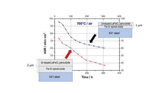
Figure 7 shows the ASR values for M-coating and S-coating samples during air exposure at 700 °C for 300 h. It is observed that the ASR is characterized by a common declining trend accompanied by a tendency of the evolution curves to linearize after a few dozen hours. This behavior may be attributed to a gradual change in electrical conductivity of the coatings, most likely linked to a diffusional effect or a structural coating improvement during the exposure at 700 °C. In spite of the higher coating thickness, the S-coating sample shows lower ASR values throughout the time span of the experiments. As compared to 60 mΩ cm
2 of the M-coating sample, the final ASR of S-coating is 37 mΩ cm
2, which is comparable to the reported values of other dual spinel–perovskite coatings of similar thickness, such as the dual Co
3O
4-LaCoO
3 coating [
13]. The approximate values of coating conductivity can be calculated from the ASR measurements, considering that ASR is definable as the product of electrical resistivity (ρ) and coating thickness (Δx) according to:
Thus, using the ASR values at 300 h and a coating thickness of 1 µm and 2 µm for the M-coating and the S-coating samples, respectively, an average conductivity of 0.0054 S/cm can be estimated for the S-coating. This value is about three times higher than that of the M-coating, which is 0.0017 S/cm. In conclusion, these results are a further confirmation that a Sr-doped LaFeO3 was formed during the thin-film perovskite coating synthesis and that Sr incorporation into the LaFeO3 layer can effectively improve the overall thin-film perovskite coating conductivity at the temperatures of interest for SOC interconnect applications. As a further characterization step, the effectiveness of such thin film combined perovskite–spinel coatings in inhibiting the chromia subscale growth at the steel/coating interface will also be analyzed in the near future since the production of coatings with high oxygen gas-barrier properties is an additional important aspect for predicting the stability and lifetime of coated SOC interconnects.


