Article

Validated Analytical Model of 8/6 and 10/8 Switched Reluctance Motors

1
Astronika Sp. z o. o., ul. Bartycka 18, 00-716 Warsaw, Poland
2
Electrical Power Engineering Institute, Faculty of Electrical Engineering, Warsaw University of Technology, 00-662 Warsaw, Poland
3
Legrand Polska Sp. z o. o., ul.Waryńskiego 20, 57-200 Ząbkowice Śląskie, Poland
4
Symkom Sp. z o. o., ul. Głogowa 24, 02-639 Warsaw, Poland
5
ILF Consulting Engineers Polska Sp. z o. o., ul. Osmańska 12, 02-823 Warsaw, Poland
6
KGMG Sp. z o. o., 22-100 Warsaw, Poland
7
Energix Renewable Energies, Plac Stanisława Małachowskiego 2, 00-066 Warsaw, Poland
8
Institute of Mechanical Engineering, Warsaw University of Life Sciences, 02-787 Warsaw, Poland
9
British-American Tobacco Polska S. A., ul. Tytoniowa 16, 16-300 Augustów, Poland
*
Authors to whom correspondence should be addressed.
Energies 2022, 15(2), 630; https://doi.org/10.3390/en15020630
Submission received: 6 December 2021 / Revised: 2 January 2022 / Accepted: 11 January 2022 / Published: 17 January 2022

Abstract

:
The aim of this work was to develop a parameterized analytical and FEM (Finite Element Method) model of a switched reluctance motor. The developed analytical model was used to assess the performance of these types of motors, and is determined to be a tool for comparing and evaluating switched reluctance motors of various designs. The aim of the work was also the systematization of knowledge related to the operation, structure and methods of determining the static electromagnetic torque generated by switched reluctance motors. The FEM model (ANSYS) was, also, made in order to verify physical phenomena occurring during operation of these motors. Four laboratory tests were executed as part of the work prototypes of switched reluctance motors built at Warsaw University of Technology. A parameterized analytical model was developed and implemented in MATLAB. The model operation tests were conducted and as a result, the characteristics describing the dependence of the electromagnetic torque as a function of the current and the position of the rotor were obtained. The model was validated by confronting the analytical calculations supported by FEM simulation results with the measurement results. The usefulness of the results obtained with the use of the procured models was assessed.

1. Introduction

In the second half of the 20th century, the dynamic development of switchable reluctance machines began [1,2,3,4,5]. It was caused by the following changes in industry: Development of power transistors. These components facilitated commutation and regulation of operating currents, and made it possible to use Pulse Width Modulation and employ frequencies much higher than allowed by thyristor systems [6,7]; Development of microprocessors and digital integrated circuits. The new circuits gave greater possibilities to implement control algorithms than the previous digital and analog integrated circuits [8,9]; Development of computers with high computing powers, advanced programming languages and numerical methods. These tools made it possible to execute analyzes using the finite element method and to solve differential equations in discrete time [10,11]; The overall development and the need to expand speed-controlled systems and electric motor motion control, which has not only occurred in industry, but has also appeared in new applications such as automotive vehicles, household appliances, office products and related systems with aviation. The development of the SRM is characterized by an increase in technical inventiveness. As a result of the development of the above-mentioned branches, engineers received new tools for research, design and implementation of the developed structures. The experiments conducted resulted in the growth of new solutions for switchable reluctance motors [12].
SRMs are available in many designs. Each of the possible configurations has both advantages and disadvantages. Single-phase motors are cheaper to implement and allow to achieve higher rotational velocities, but those are causing starting problems [13,14]. Multi-phase motors are characterized by lower current and torque ripple; however, those develop lower rotational speeds with the same switching frequency of the phase bands. Consequently, it is not possible to build a high-speed motor with low torque ripple as the requirement for the number of phases is contradictory. The compromise is the skillful use of a given type of motor where it meets the binding requirements [15,16].
It should be emphasized that single and two-phase machines, in particular, are suitable for applications requiring variable speed drives, and the cost of their construction is low. The place of their application is an increasingly wide range of household appliances, ventilation and air conditioning. Two-phase motors can start under various loads and are much cheaper than three-phase equivalents [17,18]. A switchable reluctance motor is unique in that the direction of the generated torque does not depend on the direction of the current flow in the windings, but on the phase sequence and the starting position of the rotor. The reluctance flux path between two opposing stator poles change accordingly to the position of the rotor poles. The phase inductance is inversely proportional to the reluctance value. It reaches its maximum when the rotor phase poles are coaxial with the stator phase poles and its minimum when the rotor poles are transverse to the stator phase poles [19,20,21,22,23]. The rotor speed can be regulated by changing the frequency of the pulses supplying the stator phase bands while maintaining the synchronism of switching the current in phase with the appropriate angular position of the rotor. The 3D model of the exemplary switched reluctance motor and its cross-section were shown in Figure 1 below.
The aim of this work was to create analytical model for four variants of the SRM motors: (a) 8/6 with a symmetrical straight poles rotor; (b) 8/6 with a symmetrical oblique poles rotor; (c) 10/8 with a symmetrical straight poles rotor; (d) 10/8 with an asymmetric straight poles rotor. The models were used in order to obtain results of the static torque produced by the motor. This parameter was the main criterion of comparing results with those obtained from measurements. Additionally, FEM models were prepared in a way that enabled deriving the distribution of the electromagnetic field during the SRM motor operation. 3D models were procured using ANSYS software for motor variants with straight poles. One of features during calculations was to highlight the amendment of static torque caused by the SRM construction modifications. Models were procured on the basis of analytical calculations, presented in later chapters of this manuscript. Analytical calculations were executed mostly by means of the MATLAB software and presented dependencies. The novelties of the procured models were highlighted below:
  • Vast customization of model elements which is essential to test different scenarios;
  • Optimization algorithm;
  • Model can be used in order to witness physical phenomena in 3D environment;
  • Accurate calculations;
  • Validated by an experiment.

2. State of the Art

In recent years, there has been a growing interest concerning the SRM electric motors. These motors fall into three categories: reluctance motors, permanent magnet motors and hybrids, which are a combination of both. The reasons for the aforementioned increase in interest in the SRM motors are mainly articles [24,25]: Demand for medium and high velocity electric motors to power modern vehicles, manipulator arms, robotics and space technology [26,27]; Economic conditions—an attempt to make savings in the operation of working machines by resigning from expensive in use and maintenance of mechanical gears, replacing them with a magnetic gear [28,29]; As previously mentioned, the elimination of rare earth metals [30].
Publication [31] presents an innovative switched reluctance motor (SRM) for traction applications in cars. The results of electromagnetic and mechanical simulation of the proposed engine for operation at 50,000 rpm are presented. The SRM is designed to withstand the rotor stress caused by centrifugal force while producing an output of 60 kW. The high speed of operation allows for a smaller overall size which in turn leads to lower production costs. This, combined with high power output, makes this design a good candidate for mass production of hybrid electric vehicles [32,33].
The Switched Two-phase Reluctance Motor is gaining more and more attention in both high-speed and unidirectional applications due to its moderate performance and cost compared to its three-phase SRM and single-phase counterpart. The 8/4-pole two-phase SRM has been introduced in the article to replace the common AC series motor to drive the grinder in this article. Optimization of the structure was executed, especially for the stepped air gap, FEM calculations and prototype experiments were presented [34].
Several good control algorithms for such a machine have also been developed. Article [35] deals with the "optimal" Switched Reluctance Motor (SRM) control algorithm. The principle of this control method is based on the Maximum Torque Per Ampere (MTPA) criterion which favors the maximum mean torque value, regardless of the torque ripple, compared to the commonly used method which favors constant torque control. The proposed control method uses pre-calculated optimal positions of the current pulses of the start-up and stopping of the rotor [36,37]. These optimal values are obtained by numerical simulations on the basis of a data set obtained as a result of an actual measurement of the electromechanical system of the SRM machine and its power converter. The article describes the mathematical model of this SRM and the measurement method [38,39,40]. The algorithms used in the SRM simulation also take into account the non-linear iron core of the SRM, maximum voltage limitation (maximum supply voltage), high speed area and current limits [41,42,43].
The work of the team [44] on a new Toroidal Winding Reluctance Machine (TSRM) with a single continuous multiple winding is noteworthy. This machine can be driven by a 6-switch asymmetric converter that supplies currents from the unipolar coils, or a 12-switch voltage source converter that supplies currents to the bipolar coils. The publication describes the magnetic design of the TSRM and electronic power control, and compares its performance to a Conventional Switching Reluctance Motor (CSRM) and to a previously described switched toroidal format reluctance machine that uses six discrete winding coils in a three-phase star connection (WSRM) driven by a voltage source inverter. Fixed magnetic circuit design 6-4 CSRM was selected for comparative analysis of three machine topologies using static and dynamic finite element simulations.
The team of authors [45] noted that most of the existing estimation and control models for commutated reluctance machines (SRMs) ignore the dynamic effects of mutual coupling between different phases. While this may be acceptable in some typical industrial applications, this simplification can significantly degrade the drive performance and the accuracy of the estimated quantities. The paper presents an improved representation of the SRM by defining an appropriate finite element model of the machine. This model makes it possible to accurately estimate the rotor position and electromagnetic torque for any current configuration. The necessity and feasibility of such an approach is illustrated in the case of the 3-phase SRM 6/4. The accuracy of the torque and position estimation provided by the proposed methodology is verified by measurements on the prototype 3-phase SRM 6/4.
As for the more common use of SRM electric machines in electromobility, it is possible to learn a lot from the paper [46], which concerns the design and construction of a prototype of a light (one-person) electric vehicle powered by a switched reluctance SRM and controlled by a low-voltage half-bridge high-current converter. The machine will provide the drive to drive a light electric vehicle. The idea is to use the vehicle in order to aid disabled people using advanced design methodology.

3. Analytical Method for Calculating the Torque of the SRM Applied in the Model

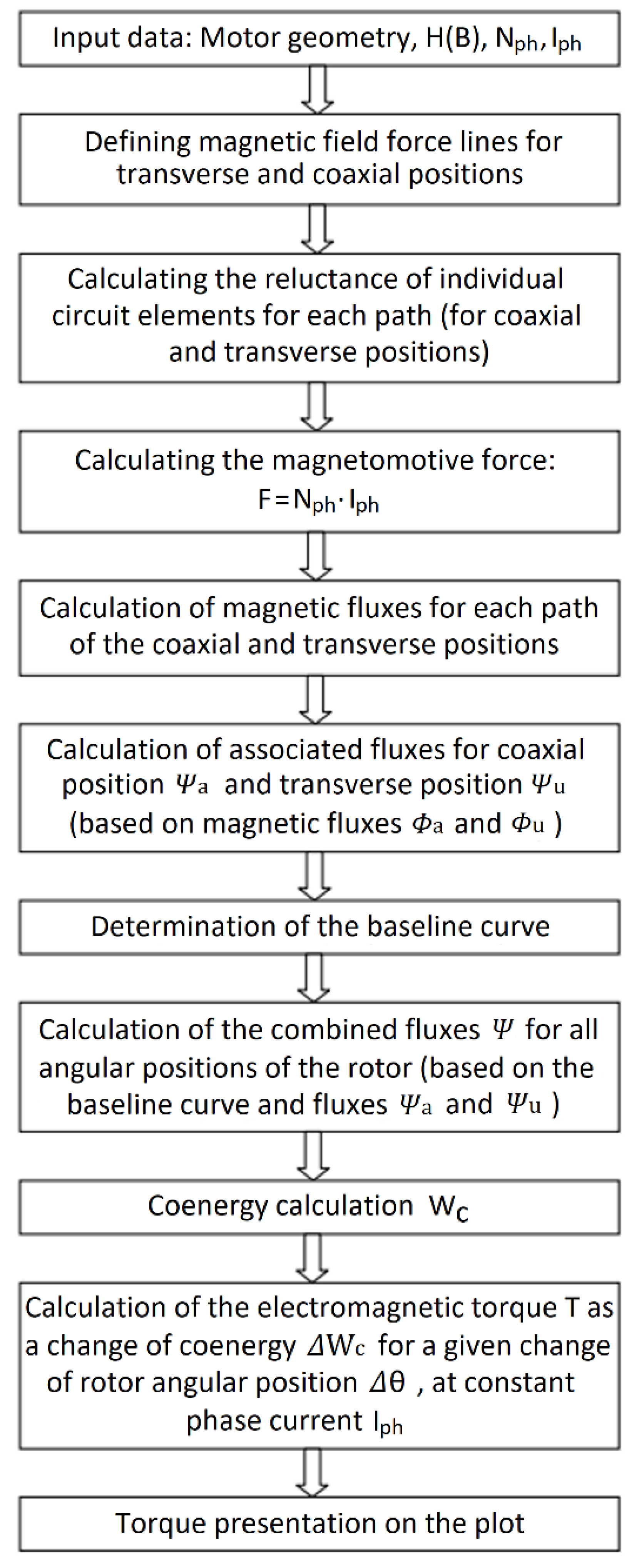
3.1. Detailed Description of the Method

The development of a mathematical model representing the operation of the SRM is a difficult task due to the sequential operation of this type of motor. It is not possible to develop a substitute diagram describing the operation of the SRM motor with constant values of the quantities defining the magnetic circuit, such as reluctance, associated flux or inductance. This is because any change in the angle of the rotor θ or phase current Iph changes the above-mentioned parameters. When describing one motor phase band, it can be characterized by resistance R and inductance L(i,θ). The voltage drop across the motor phase band is equal to the voltage drop across the resistance R and the change in associated flux over time ψ(i,θ):
v = R · i + d Ψ ( i , θ ) d t  
where (i,) = L(I,θI; L is dynamical inductance.
Since the change in the value of the associated flux depends both on the change in the angular position and on the change of the current intensity, Equation (2) can be written as follows:
v = R · i + Ψ · d i i · d t   + Ψ · d θ θ · d t  
By multiplying Equation (2) by current i it is possible to obtain the value of the input instantaneous power:
v · i = R · i 2 + i · Ψ · d i i · d t + i · Ψ · d θ θ · d t  
The electromagnetic torque can be determined from the power equation. Therefore, it is possible to present Equation (4):
v · i   · d t = R · i 2 · d t + i · Ψ · d i i + i · Ψ · d θ θ  
The expression on the left represents the change in input energy. The three components on the right represent the change of energy into heat, the change of the energy of the magnetic field, respectively, dWF and mechanical work dWM. Using Equation (4) magnetic field energy change and mechanical work can be written as:
d W F + d W M = i · Ψ · d i i + i · Ψ · d θ θ  
The change in the magnetic field energy depends on the current and the angular position of the rotor:
d W F = i · W F · d i i + i · W F · d θ θ  
It is possible to derive an equation for mechanical work from Equation (5):
d W M = ( i · Ψ θ W F θ ) · d θ + ( i · Ψ i W F i ) · d i  
Knowing the magnetization curve (Figure 2), it is viable to determine the dependence of the magnetic field on the current and associated flux at a constant angular position of the rotor:
W F = 0 Ψ i · d Ψ  
W F = i · Ψ 0 i Ψ · d i
The partial derivative of the expression (9) on the current, gives:
W F i = i · Ψ i   + Ψ   0 i Ψ i · d i = i · Ψ i  
Substituting Equations (7)–(10) the second term to the right of Equation (7) is eliminated and it takes the following form:
d W M = ( i · Ψ θ W F θ )
The change in mechanical work described in Equation (11) can also be expressed as the generation of the electromagnetic torque Ts by one phase as a result of changing the angular position of the rotor:
T s = W M θ = i · Ψ θ W F θ  
This expression can be simplified by introducing the Wc magnetic co-energy:
W C = 0 Ψ i · d Ψ  
At this point, it should be noted that when working on the linear part of the magnetization characteristic, the magnetic field energy and the co-energy are equal. It is different if the work on the non-linear range of the magnetization characteristics of the electrical sheet (in medium and deep saturation) is taken into account. Then the difference between the magnetic field energy value and the co-energy value becomes visible. The total input energy can be written as the sum of the magnetic field energy and the co-energy, which is equal to the current i multiplied by the associated flux ψ:
W F + W C = i · Ψ  
After calculating the partial derivative of Equation (14) while changing the angle of the rotor position θ, the following is obtained:
W C θ = i · Ψ θ W F θ  
From the Equation (15) the instantaneous electromagnetic torque Ts (i, θ) produced by each phase are given as the partial derivative of the phase co-energy change for the change in the rotor angle θ at constant current and is described by the equation:
T s ( i , θ ) = W C ( i , θ ) θ ; i = c o n s t .    
The total instantaneous torque is the sum of the torques produced at a given torque by all phase bands:
T e = S = 1 q T s ( i , θ )    
where q is the number of phase bands in the motor. The average torque Tav can be obtained by integrating the expression (17):
T a v = 1 θ s k 0 θ s k T e · d θ  
where θsk is the angle by which the jump occurs. In the case of the linear flux model (ignoring the saturation phenomenon), that is ψ (i, θ) = L (i, θ) ∙ i:
W C = 0 i Ψ · d i = L ( θ ) · i s 2 2  
Therefore, the torque can be expressed by equation presented below:
T s ( i , θ ) = i s 2 · d L 2 · d θ    
Equation (20) shows that in an SRM motor the torque is independent of the sign of the phase current and depends on dL/dθ. The absolute value of dL/dθ contributes to the increase in the mechanical torque produced by the motor. The quadratic dependence of the electromagnetic torque practically occurs only for very low currents. Usually, the torque increases linearly with the current until the poles of the stator and rotor coincide and the material they are made of begins to saturate.

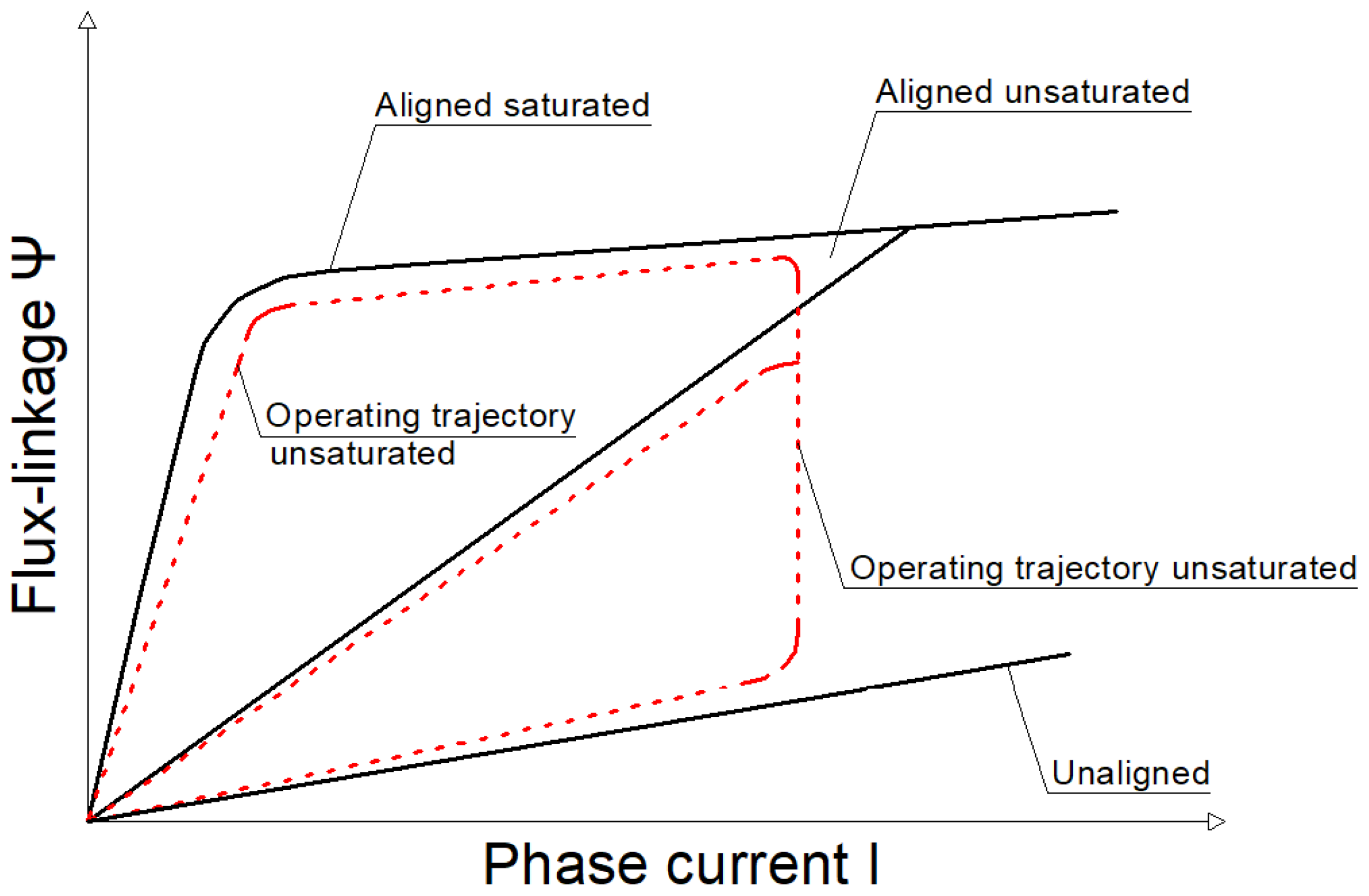
3.2. Conversion of Electro Mechanical Energy

To describe an SRM motor, it is necessary to know the reluctance and inductance (or associated flux) depending on the rotor angle and phase current. Nonlinear relations between some of the above-mentioned quantities result from the nonlinear magnetization characteristics of the material from which the machine is made. The elements that characterize the machine are: electromagnetic torque and utilization factor. These elements are mainly determined on the basis of the energy relationship. The co-energy contained in Equation (12) can be converted into mechanical work with each rotor pitch and is equal to the area enclosed by the operating point trajectory, on the characteristics of the associated flux ψ as a function of current i. Exemplary characteristics ψ-z with the designated energy regions, which is converted into mechanical work, are shown in Figure 3. These are idealized characteristics and show the area of transformed energy for two types of SRM motors: one that uses material saturation (non-linear) and one that does not use material saturation (linear).
By analyzing the characteristics presented in Figure 3 it can be seen that a motor using the saturated part of the characteristic is able to return a greater part of the energy in the form of mechanical work than a motor operating without material saturation at the same phase current. In order for the area of returned energy to be as large as possible, the distance between the associated flux for the coaxial position ψa and for the transverse position ψu must be as large as possible. In order to increase the associated flux for the coaxial position, the width of the stator and rotor poles should be increased. To reduce the associated flux for the transverse position, the width of the stator and rotor poles should be reduced. It is not possible to meet both of these requirements at the same time because those are contradictory, therefore, when designing a motor, it is necessary to work out the optimum in which it is possible to obtain the highest value of the returned energy. From the characteristic ψ-i, it can also be seen that the angle slope of the straight line behind the “knee” for the coaxial position is less than for the transverse position. As a result, as the current increases, both curves get closer to each other and, therefore, there is a certain limit to which it is worth increasing the current flowing through the motor phase band. Above this value, increasing the current is unprofitable, because the increase in the area of which energy is converted into mechanical work is insignificant and most of the energy is converted into losses.

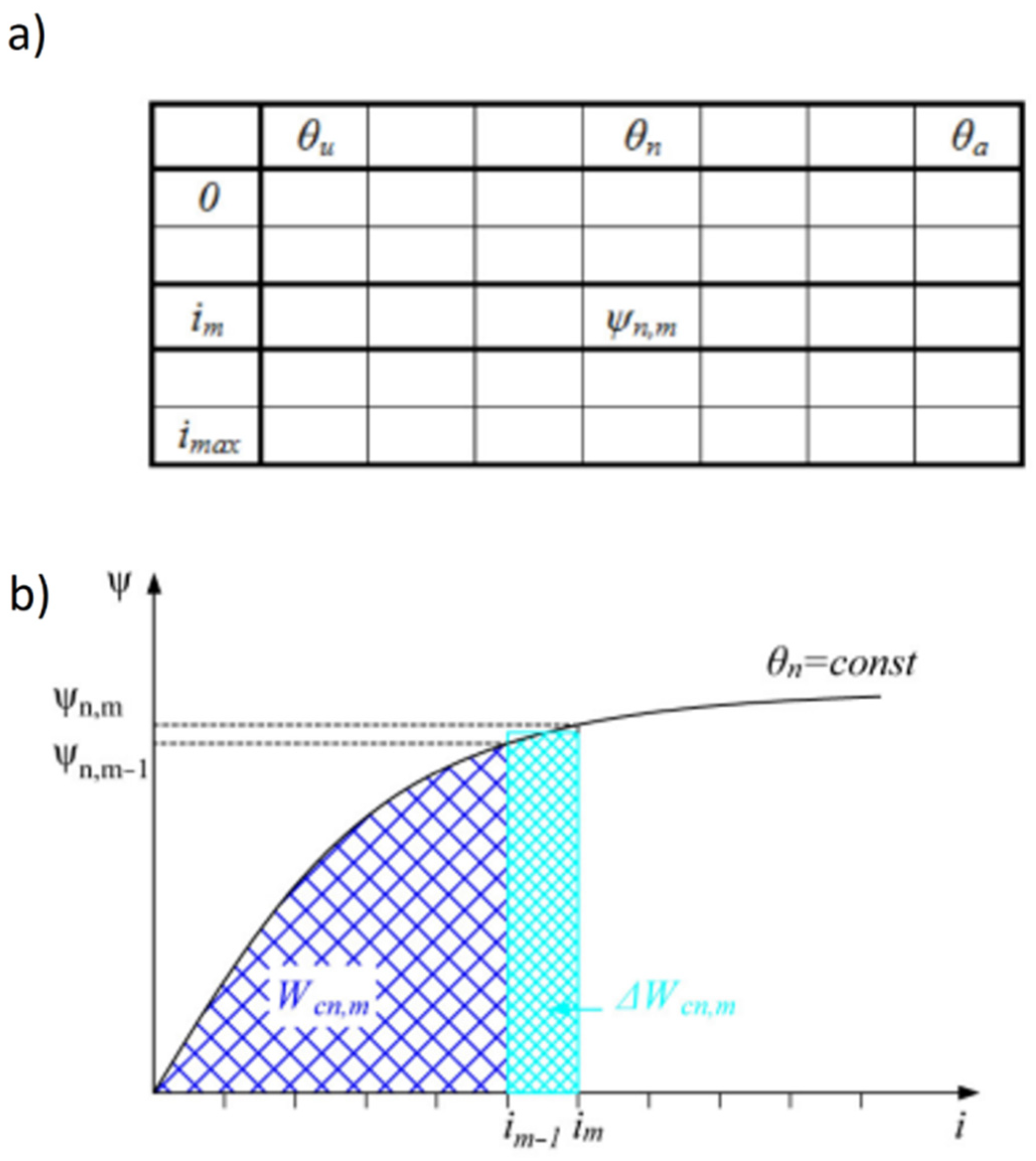
3.3. Calculations of the Static Torque Characteristics

The associated flux values for a given current and a given angular position of the rotor are determined from the model curve. The determined data is stored in a two-dimensional array, the structure of which is shown in Figure 4.
The instantaneous torque T of the motor is calculated as the differential quotient from the change in co-energy ∆Wc to the change in the rotor position angle ∆θ at constant phase current i. The calculations are performed in the sequence according to the following formulas:
W c n , m = Ψ n , m + Ψ n , m 1 2 · ( i m i m 1 )    
W c = W c n , m = W c n , m 1 + θ W c n , m    
where n is the period between the points in the angular pitch and m is the current index. The applied calculation procedure averages the increase in the area corresponding to the co-energy ∆Wcn, m is calculated as the area of the rectangle. In order to obtain a static torque, the following formula should be used:
T = W c θ ; i = c o n s t

3.4. Structure of the Analytical Model

The scheme of performing calculations by the analytical model implemented in this paper is shown in Figure 5. The input data are: motor geometry, magnetization characteristics of the material from which its stator and rotor are made, the number of coils wound on one phase band and the value of the current flowing through this band. First, the "stream paths" are defined. Then these two magnetic circuits are solved. The first one describes the coaxial arrangement of the stator and rotor poles, the second one—the transverse arrangement. Using the magnetization characteristics and the geometry of the motor, the determinants of individual elements of the magnetic circuit are derived. Knowing the number of turns Nph and the current flowing through the phase band Iph, the magnetomotive force F is determined. From the magnetomotive force F and the reluctance R, the magnetic fluxes flowing in the circuits are obtained for the transverse position Φu and for the coaxial position Φa. The associated fluxes ψu and ψa are determined from the magnetic fluxes Φu and Φa. These fluxes should be determined for each current value. Then, using a “calibration curve” specially developed for this method, the associated fluxes ψ are determined for the intermediate angular positions of the rotor, between the lateral position and the coaxial position of the stator and rotor poles. Knowing the associated fluxes ψ for individual phase currents Iph and angular positions of the rotor θ, the co-energy Wc is calculated. By calculating the change in co-energy ∆Wc after changing the angular position ∆θ at a constant current, the electromagnetic torque is obtained.

3.5. Analytical Model Assumptions

Before implementing the analytical algorithm for determining the torque of the switchable reluctance motor, the following simplifications were assumed:
  • The model will describe the operation of switchable reluctance motors with parallel faces to the stator and rotor poles. This assumption was made due to the much greater popularity of the design of straight-pole motors than of trapezoidal pole-shaped motors;
  • The magnetic flux disburdening effect, described in more detail in publication [25], was omitted;
  • When calculating the associated fluxes for track 2 in the coaxial position and for all seven tracks in the transverse position, it was assumed that the sum of the reluctances of the individual magnetic guide elements and the air gap is equal to the air gap reluctance. In electric motors, the air gap is the main source of magnetic resistance and preferably should be as low as possible. In the case of switched reluctance motors, the air gap changes its geometry (mainly length) depending on the angular position of the rotor. The maximum length is achieved for the transverse position and the resistance of the slit in this position to the flowing magnetic flux is so great that the reluctances of the individual elements of the magnet guide are negligibly small;
  • The entire flux is enclosed in the magnetic circuit, i.e., there is no flux bypass effect at the ends of the stator and rotor package;
  • The field force lines in the stator and rotor poles are parallel to the poles;
  • The windings are treated as rectangular blocks and the space between the poles of the stator is only partially filled with the windings;
  • The field force lines in the stator and rotor yokes are concentric;
  • The field force lines in the air-gap consist of concentric arcs and rectilinear segments;
  • The magnetic conductivity of the shaft is ignored;
  • In order to calculate associated fluxes for all rotor positions only one standard curve was used.

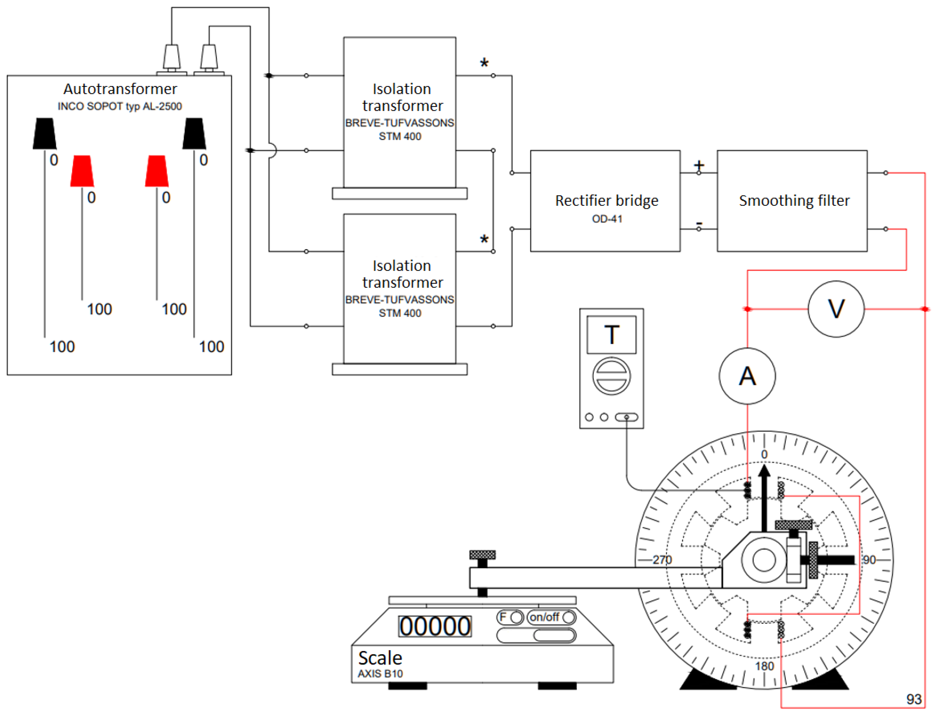
4. Laboratory Measurements of Modeled 8/6 and 10/8 Motors

During the measurements, the following four prototypes of switched reluctance motors with two rotors of different designs were tested:
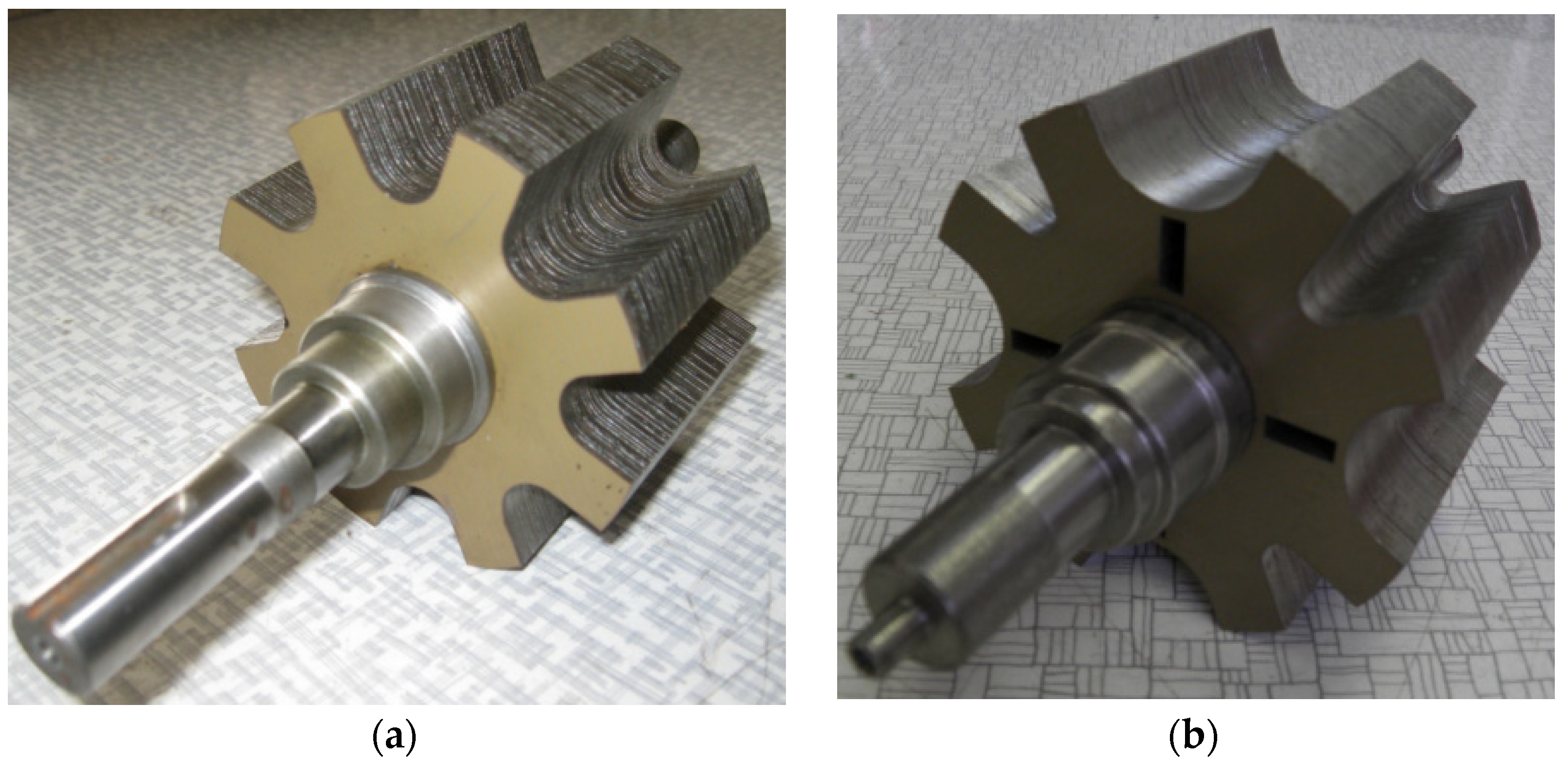
  • SRM 8/6 with symmetrical straight poles rotor;
  • SRM 8/6 with symmetrical oblique poles rotor;
  • SRM 10/8 with symmetrical straight poles rotor;
  • SRM 10/8 with an asymmetrical straight poles rotor.
Motor construction parameters were presented in Table 1 above while Figure 6 shows the external appearance of each of the two motor types. The 8/6 motor structure had to be prepared before starting the tests. As part of the preparatory work, the windings of the coils lying on the opposite poles of the phase band were ordered and paired. After the coil windings were paired, homogeneous terminals were determined for each of the coils and the end of the first coil was connected to the beginning of the second, within one phase band. Additionally, each phase strand was distinguished by a different color of the heat-shrinkable sleeves applied to the output wires. The wires of the ends of the phase bands were connected to a terminal block mounted on the stator of the motor. The motor was bolted with a clamp to the base. The tests included the measurement of the static torque generated by the motors depending on the angle of the rotor position. In order for the obtained results to be burdened with the lowest possible error, before starting the measurements the scale was “re-set” with the TARA button, and the measuring arm was balanced with a weight placed on it. Due to the easier implementation of the measurements, it was decided to change the position of the rotor from the coaxial position (stable position) to the transverse position (unstable position). To obtain an exact starting position, the motor was pre-energized with a current of 1 A (to attract the rotor poles by the stator poles). Then, using the screw (used to adjust the worm gear), the position of the arm was adjusted so that it applied to the balance, but did not exert any force on it. The pointer for reading the swivel angle on the protractor has been moved to the 0° position. If you tried to take measurements from the lateral position to the coaxial position, there would be a problem with the exact positioning of the arm in the home position (due to the instability of the lateral position). Despite the measurements from the position of the rotor poles in the coaxial position to reaching the transverse position, the results and the plotted torque characteristics have the opposite course. It was decided to reverse the order of the results because the analytical model proposed in the paper calculates the characteristics of the motor and plots the torque diagrams from the transverse to the coaxial position. Thanks to this, the comparison of the measurement results with the calculation results were facilitated.
The diagram of the measuring system used to determine the characteristics of the static torque of the motors are shown in Figure 7.
The measurement procedure was repeated for the following current values: 5, 10, 15, 20 and 25 A. After testing a given motor for all five current settings and moving the rotor from the coaxial position to the transverse position, the tested object was replaced and another one was tested in accordance with the procedure. During the measurement, the voltage level on the phase winding was observed and the winding temperature was monitored. When it reached 100 °C, the measurement was stopped, and the machine waited for it to cool down. It was observed that both the SRM 10/8 and SRM 8/6 machines were heating up and required to stop the measurements for the currents of 20 A and 25 A. When executing measurements at lower current values, the windings did not heat up intensely, and those test runs could be performed without breaks for the machine to cool down.

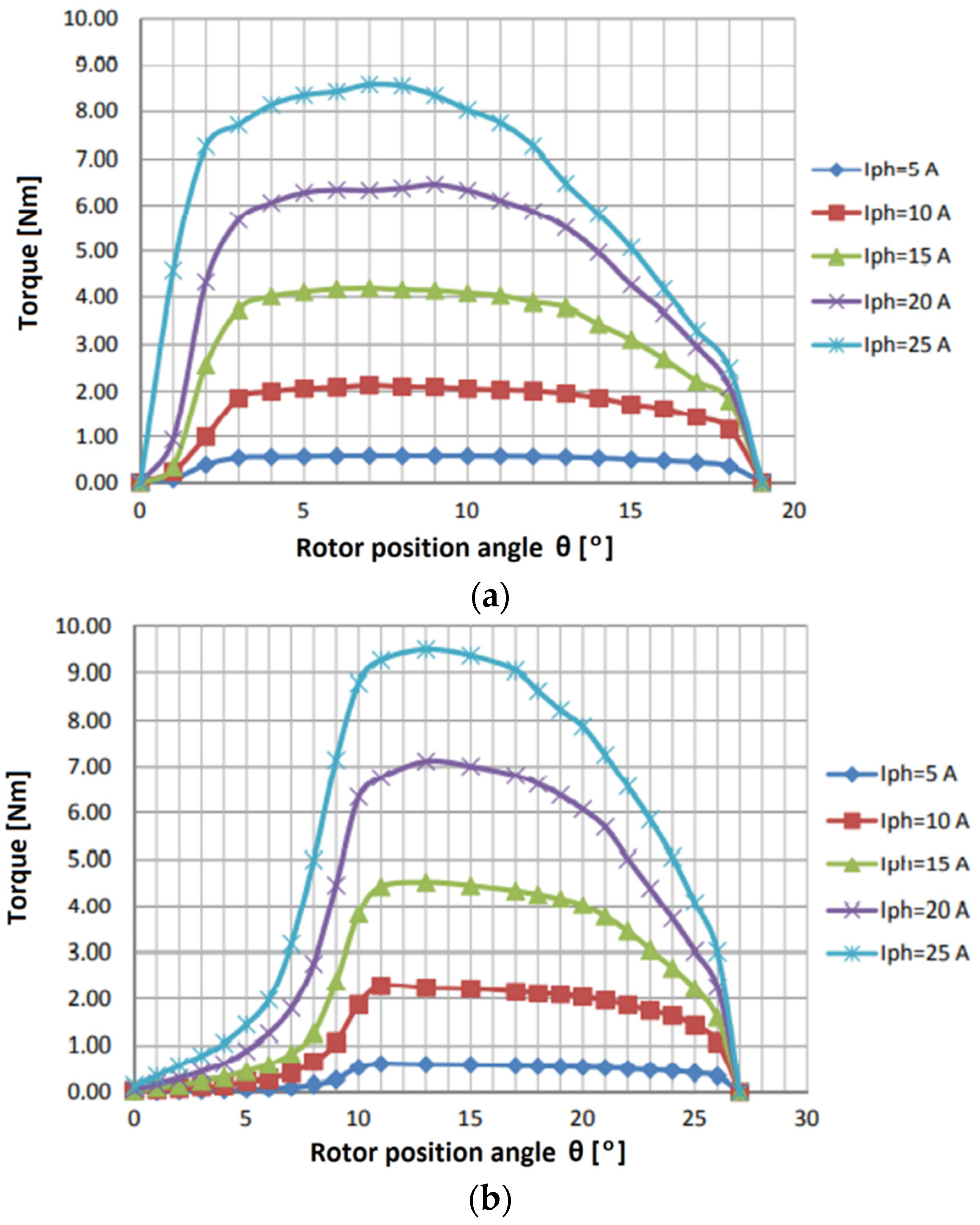
4.1. Measurement Results of the Static Torque Produced by the SRM 8/6 Motor with a Symmetrical Straight Poles and Oblique Poles Rotor

Figure 8 presents photos of the tested rotors of motors 8/6, switched symetrically reluctance: (a) straight poles, (b) oblique posts. Figure 9 shows the significant characteristics of the static torque generated by the tested SRM 8/6 motor with a symmetrical rotor as a function of the rotor angle θ and the value of the phase current Iph: (a) staight poles, (b) oblique posts.

4.2. Measurement Results of the Static Torque Produced by the SRM 10/8 Motor with a Symmetrical and Asymmetrical Straight Poles

Figure 10 shows the appearance of the tested rotors of 10/8 switchable relucatnce machines: (a) symmetrical, (b) asymmetric. Figure 11 shows the characteristics of the static torque generated by the tested SRM 8/6 motor with a staight-pole rotor as a function of the rotor angle θ and the value of the phase current Iph: (a) symmetrical, (b) asymmetric.
The rotor of this design has an asymmetry introduced in the geometry of its poles distribution. The rotor can therefore be considered as a structure with two alternating polar pitches. In the case of this motor, two series of measurements were executed. During the first series, the torque characteristics were tested for a smaller angular distance between the nearest rotor poles, and during the second series, for a larger angular distance. The above-mentioned values of the polar divisions are respectively 36° and 54°. As can be seen, the sum of the two pole scales of an eight-pole asymmetric rotor is equal to the sum of the two pole scales of an eight-pole symmetrical rotor.

5. Analytical Model Calculations and FEM Simulation Results

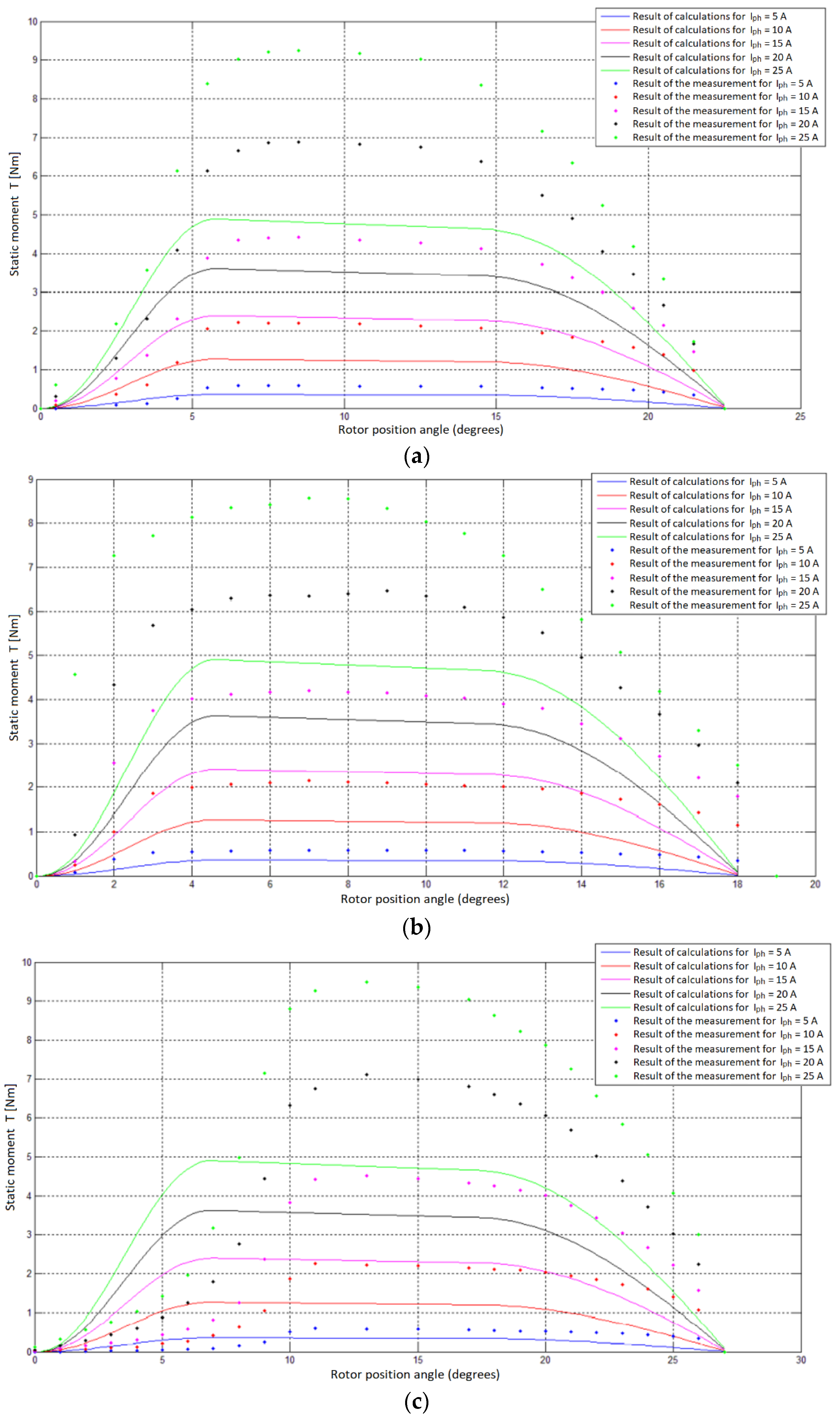
5.1. Juxtaposition of Laboratory Measurements and the Results of Calculations Obtained with the Use of the Developed Analytical Model

Figure 12 shows a comparison of the calculation results (solid lines) with the measurement results (dotted lines) for a symmetrical SRM 8/6 with: (a) straight poles, (b) oblique posts. Figure 13 presents the comparison of the calculation results (solid lines) with the measurement results (dotted lines) for the SRM 10/8 straight poles: (a) symmetrical, (b) asymmetric (angle 36° between the poles), (c) asymmetric (angle 54° between the poles).

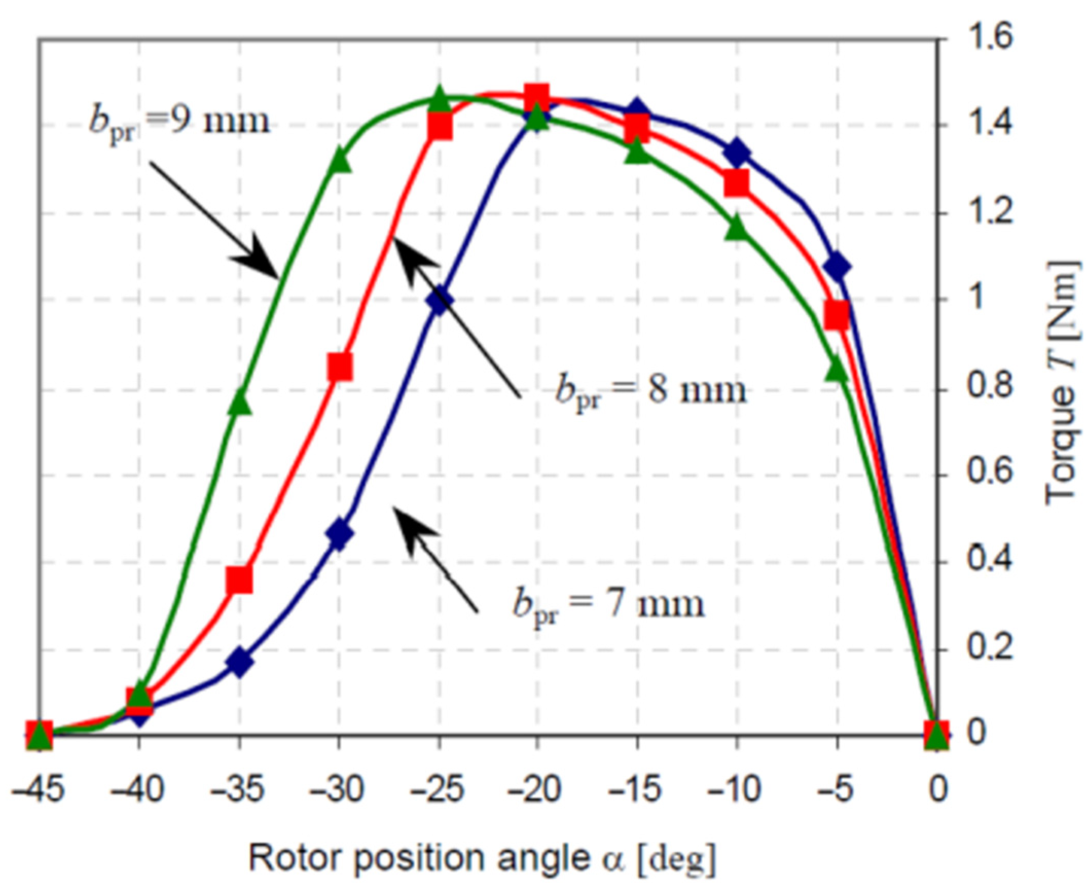
5.2. Impact of Rotor Pole Width Parameter

To simulate the effect of rotor pole width during the analytical simulation, the tr parameter was modified without introducing changes to the remaining geometrical dimensions of the machine. The static moment calculations were performed for tr of 14, 16 and 18 mm. Figure 14 shows the static torque characteristics as a function of the rotor position angle θ at the phase current Iph = 25 A, for three rotor pole widths.
Analyzing the characteristics shown in Figure 14, it can be seen that the width of the rotor poles has little effect on the maximum value of the torque produced by the switched reluctance motor. The width of the rotor pole is clearly visible in the angular characteristics of the torque generation of the motor. As the width of the pole increases, the torque generation zone is slightly widened and shifted on the angular characteristic towards the transverse position. The maximum torque value remains practically unchanged. An increase in the width of the rotor pole only changes the position of the rotor at which the maximum torque is achieved. In Figure 15, a similar family of torque characteristics for different rotor pole widths are presented, obtained as a result of computer calculations using the finite element method. While comparing the characteristics families in Figure 14 and Figure 15 it can be seen that the character of the changes shown is the same in both cases. This means that the proposed analytical model performs calculations that can be used not only for quick initial torque calculations, but also for refining the design of the motor being modelled. In order to obtain information about the average value of the torque that is produced in the period by a given phase band, the areas determined by the torque curves for each of the five values of the rotor pole width were integrated. The mean torque as a function of the rotor width is shown in Figure 16.
Analyzing the course of the characteristic from Figure 16 it can be seen that the width of the rotor pole does not have a large impact on the value of the average static torque developed by the motor. However, there is a certain optimal rotor pole width at which the motor develops its highest average torque. In the case of the tested structure, the optimal rotor pole width is 16 mm.

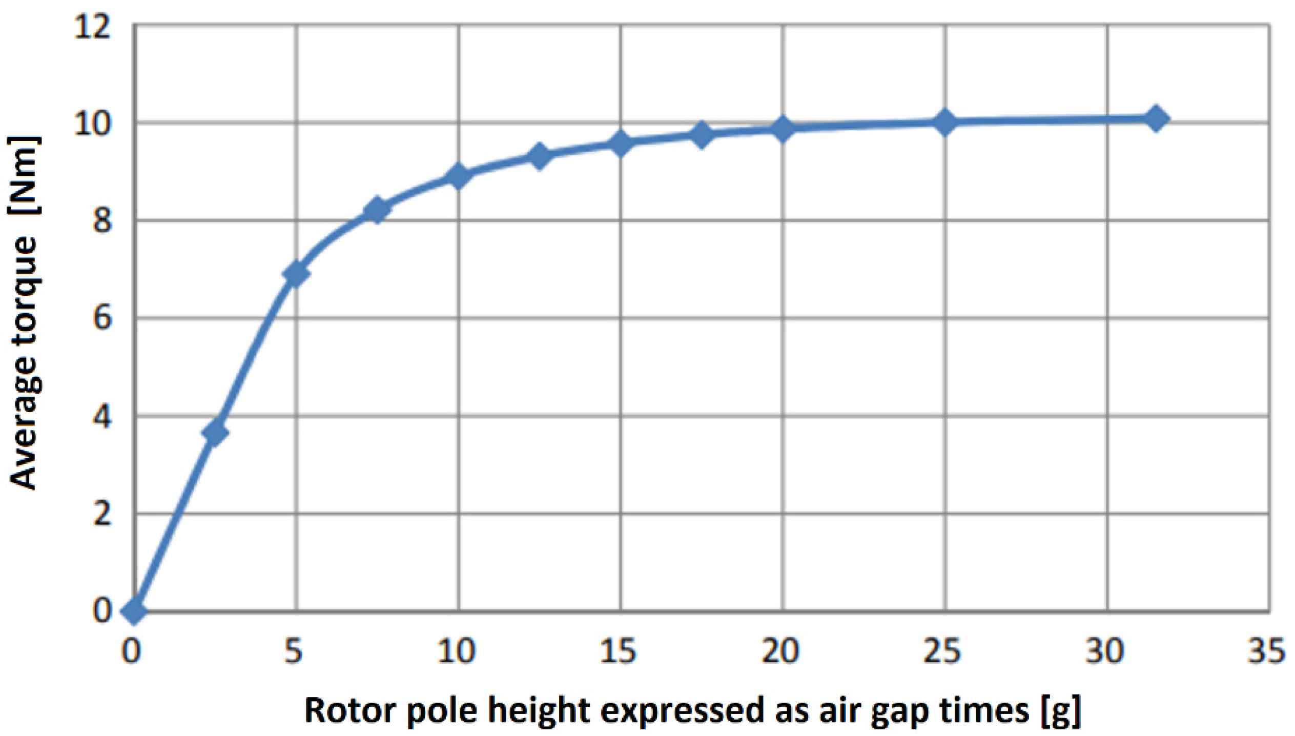
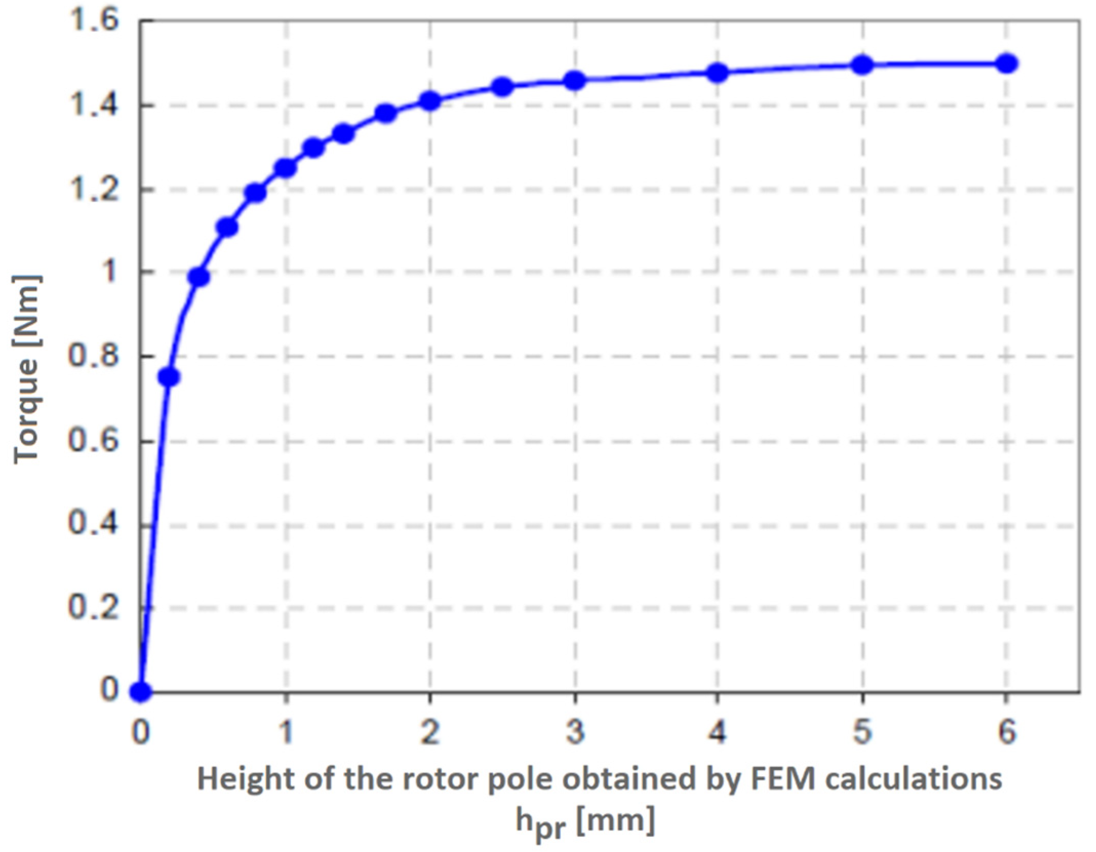
5.3. Impact of Rotor Pole Height Parameter

Changing the rotor height, the value of the rotor yoke width was kept constant, which meant that in the simulation program, with the increase of the rotor pole height, the internal diameter of the rotor had to be reduced while maintaining a constant rotor yoke width. The exact values of the geometric dimensions that changed are presented in Table 2, the remaining parameters had the values set in accordance with Table 1. The simulation was performed for the phase-band current equal to Iph = 25 A, changing the height of the rotor pole within the range of 1 mm to 12.6 mm. Relating these rotor pole heights to the air gap value, those ranged from 2.5 to 31.5 times the air gap. Figure 17 shows the dependence of the average torque produced by the motor on the pole height given in millimeters, and also in Figure 18 with respect to the multiplicity of the air gap. Looking at the characteristics shown in Figure 18 it can be seen that the highest increase in torque produced by the motor is recorded for the height of the rotor pole ranging from 0 to 5 air gaps. By increasing the height of the pole in the range from 5 to 20 air gaps, it can be seen that the speed of the torque increase, significantly decreases. Further increasing the height of the rotor pole (more than 20 slots) is unjustified. The simulations executed are consistent with the information contained in [20] concerning the changes of this nature introduced into the motor design. Figure 19 represents the dependence of the maximum torque as a function of the rotor pole height obtained as a result of calculations using the finite element method. Comparing the characteristics from Figure 17 and Figure 19 it can be seen that in both cases the observed nature of the changes is the same.

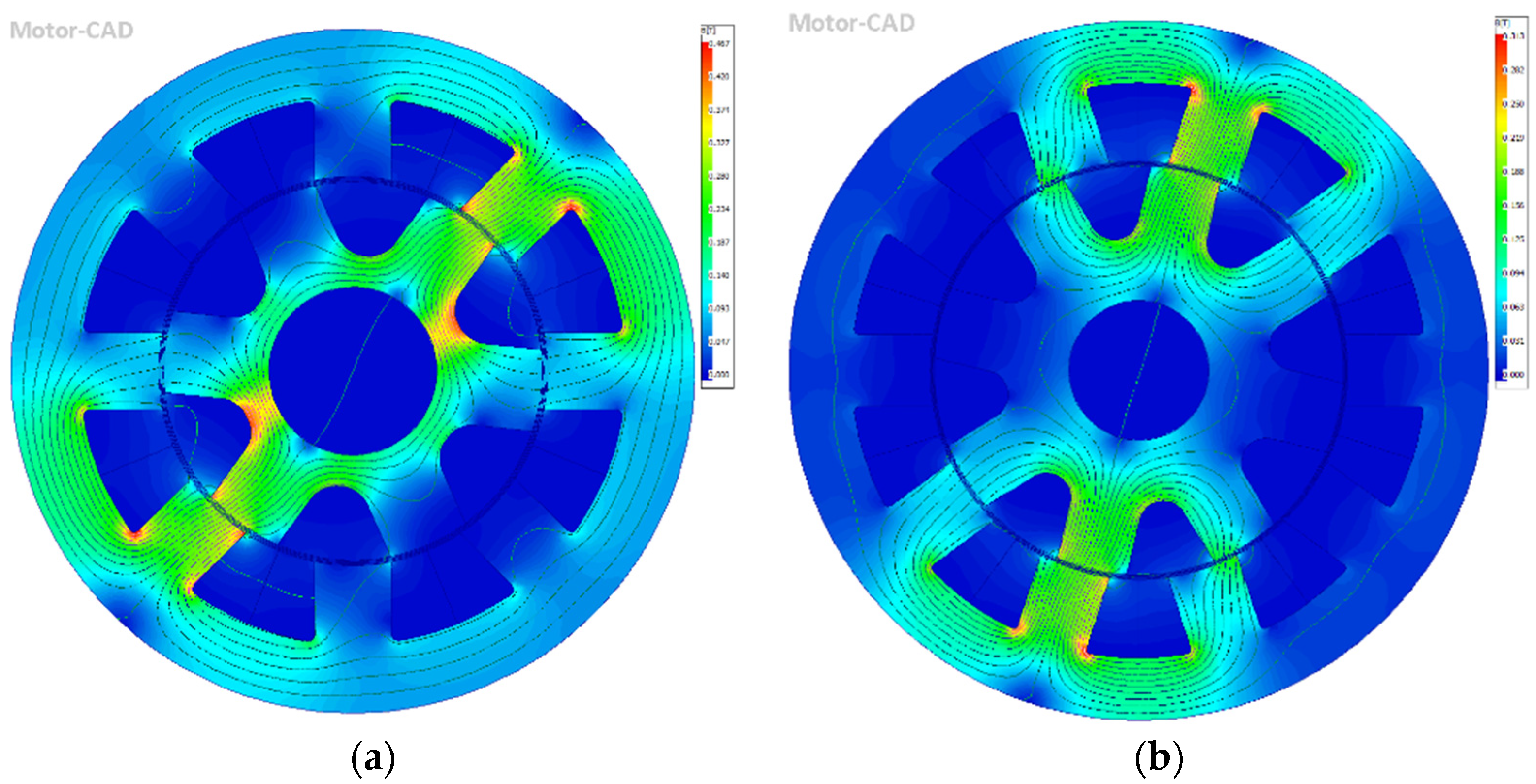
5.4. FEM Model Results

FEM models were prepared for 8/6 symmetrical motor and 10/8 symmetrical motor with straight poles. The phenomena verified by the FEM model was the distribution of associated magnetic flux lines. 3D models for those motors were presented below in Figure 20.
Figure 21 shows the results of the FEM analysis the distribution of related magnetic flux lines for the electric machine: (a) 8/6, (b) 10/8.

6. Conclusions and Summary

The torque characteristics obtained by the model for individual current values have a typical course (Figure 12a). Looking carefully at the slopes of the torque rise (from 0° to 5° of the angular position of the rotor), it can be seen that the model in this range clearly reflects the characteristics measured, especially for currents of 20 A and 25 A. In the torque rise zone for currents 5 A, 10 A and 15 A, a significant deviation of the modelled torque values from the measurement results are visible. The reason for these differences is the use of one model curve for the model calculation of all moment curves. Looking at the further course of the torque, we can see that the model gives its maximum value at the rotor position angle of about 7°. Looking at the measurement results, it is possible to see that the moment reaches its maximum for an angle of 12°. A slight decrease in the torque value is visible in the angular deflection of the rotor from 7° to 18°. For angles greater than 18°, a strong decrease in the moment is visible up to 0 achieved in the coaxial position (for a deflection angle of 30°). In the case of the measurement results, a sharp decrease in the produced torque is visible starting from 15°. Comparing the results in this zone, it can be seen that the modelled torque curves significantly differ from the curves measured, especially for phase currents equal to 15 A, 20 A and 25 A. Assessing the overall result of the model operation for the SRM 8/6 motor with a straight pole rotor, it is possible to state that the modelled torque curves correctly give the value of the maximum torque to be expected from a given motor structure, at the given phase current. Looking at the torque curve modeled for the 8/6 SRM with an oblique poles rotor, it can be seen that, regardless of the current value, the model gives overestimated torque values, taking into account the results obtained from the measurements (Figure 12b). These results are still useful, however, as the model gives an order of magnitude of the maximum performance that can be expected from a motor of this design with an error not exceeding 10%. The reason for the discrepancy in this case may be the limitation of the model to the calculation of motors with straight poles. When modelling the characteristics for this motor, it was assumed that the rotor pole was straight, and its width was equal to the width of the pole in the middle of its height and amounts to 13.25 mm.
As a result of using the model, torque characteristics were also obtained for the SRM 10/8 motor with a symmetrical rotor and straight poles (Figure 13a). As can be seen, the shape of the curves is correct and those follow the course of the measured moment. However, the obtained results are burdened with a significant error. In the case of supplying the phase band with a phase current of 25 A, the model determined the motor torque with an error of approx. 50%, assuming that the results obtained from the measurements were accurate. A comparison of the torque curves from the measurement was made with the curves modelled for the SRM 10/8 motor with the rotor introducing asymmetry in the position of the poles (Figure 13b,c). Assessing the graphs both in terms of their course and value, it can be seen that the proposed analytical model in the case of a motor with an asymmetric rotor structure does not work. The modelled curves “do not fit” into the measurement results and give values that are lowered in extreme cases to the level of 40%. The reason for these discrepancies may be the adopted modelling method related to the assumption that the motor can be considered as two motors with rotors with different values of the polar scale. Additional modifications have been made to the rotor structure in the form of four air gaps, which is not taken into account in the developed analytical model. When comparing the results obtained with the use of the model with the measurement results, discrepancies are visible. One of the causes of errors may be the adoption of the theoretical magnetization characteristics of the material for the core. It may introduce some discrepancy in the results of the calculations compared to the calculations that would be obtained by substituting the characteristics of the electrical sheet from which the rotor and stator core are made. In the case of a 10/8 structure motor, the discrepancy between the measurement and calculation results are influenced by the method of defining the flux force lines. The geometric shape of the paths in the model is matched to the motor with the 8/6 structure. The discrepancies in the results are not caused, only, by the simplifications adopted when developing the analytical model, but also from measurement inaccuracies and the adopted method of measuring the static moment.
The main objective of this work was to develop an analytical model of a switched reluctance motor. The aim of the work has been achieved. Based on the information available in the literature regarding the creation of this type of model, an algorithm was developed and implemented in MATLAB for quick calculations of the static torque generated by switched reluctance motors. The assumptions significantly simplified the algorithm’s writing, which translated into a smaller code size, but did not significantly affect the accuracy of the results. Based on the simulations, the static torque characteristics for four machines were obtained. Two of the structures 8/6 and two of the structures 10/8. The simulations show that the proposed algorithm works well for 8/6 motors. The results obtained for 8/6 motors are correct and can be used at the initial stage of designing machines of this type. Moreover, the model investigated the influence of the width and height of the rotor pole on the obtained static torque characteristics and the mean torque value. After conducting this type of analysis, it was revealed that the usefulness of the obtained results is comparable to the same analysis carried out with the use of the finite element method. This means that the presented model can be used to fine-tune the structure and search for optimal geometrical dimensions of the machine. In the case of the 10/8 engine simulation, the results obtained using the proposed model are burdened with a significant error. The model calculates the static moment with an error of 50%. The calculation results obtained for the engine with asymmetry in the rotor structure are also subject to a very large error. This means that the model is not fully universal and is not suitable for simulating motors with an asymmetric structure and 10/8 construction.
Despite the fact that the model presented in the paper does not correctly determine the torque for motors of 10/8 construction and is therefore not a universal tool, it is worth executing further work on its development. Factors encouraging further analysis are the correct operation of the model for motors with the 8/6 structure and the speed of the analytical method compared to the finite element method. In order to check the universality of the model in detail, it is worth conducting simulations of operation for machines with a different structure, e.g., 4/2 or 6/4. One of the methods of building an analytical model that would work for the widest possible group of machines would be to separately describe the construction of machines with the most commonly used structures, e.g., 2/2, 4/2, 6/4, 8/6, 10/8 or 12/10. By implementing such a model, a given code block would be responsible for simulating a machine with a given structure. The selection of the part of the code that is to perform the calculations would be made on the basis of the number of poles in the stator Ns and the rotor Nr. The construction of analytical models of switched reluctance motors used to optimize the design of this type of machine should be one of the directions of development. The results of this study show that, despite the inaccuracies in determining the performance of the machine presented by analytical models, these make it possible to find the optimal geometric dimensions of individual elements of the magnetic circuit. Additionally, FEM model results that were derived on the basis of analytical model show the correct distribution of associated magnetic flux lines for symmetrical motors with straight poles.

Author Contributions

Conceptualization, K.B., S.Ł., M.S., Ł.K. (Łukasz Kozarek), K.G., H.C., Ł.K. (Łukasz Kolimas), T.Ż., A.S., A.B. and M.O.; data curation, K.B., S.Ł., M.S., Ł.K. (Łukasz Kozarek), K.G., H.C., Ł.K. (Łukasz Kolimas), T.Ż., A.S., A.B. and M.O.; formal analysis, K.B., S.Ł., M.S., Ł.K. (Łukasz Kozarek), K.G., H.C., Ł.K. (Łukasz Kolimas), T.Ż., A.S., A.B. and M.O.; investigation, K.B., S.Ł., M.S., Ł.K. (Łukasz Kozarek), K.G., H.C., Ł.K. (Łukasz Kolimas), T.Ż., A.S., A.B. and M.O.; methodology, K.B., S.Ł., M.S., Ł.K. (Łukasz Kozarek), K.G., H.C., Ł.K. (Łukasz Kolimas), T.Ż., A.S., A.B. and M.O.; project administration, K.B., S.Ł., M.S., Ł.K. (Łukasz Kozarek), K.G., H.C., Ł.K. (Łukasz Kolimas), T.Ż., A.S., A.B. and M.O.; resources, K.B., S.Ł., M.S., Ł.K. (Łukasz Kozarek), K.G., H.C., Ł.K. (Łukasz Kolimas), T.Ż., A.S., A.B. and M.O.; supervision, K.B., S.Ł., M.S., Ł.K. (Łukasz Kozarek), K.G., H.C., Ł.K. (Łukasz Kolimas), T.Ż., A.S., A.B. and M.O.; validation, K.B., S.Ł., M.S., Ł.K. (Łukasz Kozarek), K.G., H.C., Ł.K. (Łukasz Kolimas), T.Ż., A.S., A.B. and M.O.; visualization, K.B., S.Ł., M.S., Ł.K. (Łukasz Kozarek), K.G., H.C., Ł.K. (Łukasz Kolimas), T.Ż., A.S., A.B. and M.O.; writing—original draft preparation, K.B., S.Ł., M.S., Ł.K. (Łukasz Kozarek), K.G., H.C., Ł.K. (Łukasz Kolimas), T.Ż., A.S., A.B. and M.O.; writing—review and editing, K.B., S.Ł., M.S., Ł.K. (Łukasz Kozarek), K.G., H.C., Ł.K. (Łukasz Kolimas), T.Ż., A.S., A.B. and M.O. All authors have read and agreed to the published version of the manuscript.

Funding

This publication was created within the II edition of the competition/grant of the Scientific Council for the Discipline Automatics, Electronics, Electrical engineering of the Warsaw University of Technology.

Institutional Review Board Statement

Not applicable.

Informed Consent Statement

Not applicable.

Data Availability Statement

Not applicable.

Acknowledgments

The English proofreading of the text was performed by Iwona Elżbieta Kolimas and Eric Maclean.

Conflicts of Interest

The authors declare no conflict of interest.

References

  1. Tong, J.; Zou, Y. Design of a fuse-time testing system on STM32. In Proceedings of the 2013 International Conference on Computer Sciences and Applications, Wuhan, China, 17–19 October 2013; pp. 406–409. [Google Scholar]
  2. Makwana, J.A.; Pramod, A.; Srivastava, S.P. Auto-mation and Signal. In Proceedings of the 2011 International Conference on Energy, Bhubaneswar, India, 28–30 December 2011; pp. 1–4. [Google Scholar]
  3. Hongbo, M.; Hongmei, L.; Liwen, L.; Mingna, M.; Zhiwei, C. SRM Design Based on the Sequence Sub-space Multi-Objective Optimization. In Proceedings of the 2018 21st International Conference on Electrical Machines and Systems (ICEMS), Jeju, Korea, 7–10 October 2018; pp. 1–8. [Google Scholar]
  4. Hadke, V.V.; Thakre, M.P. Integrated Multilevel Converter Topology for Speed Control of SRM Drive in Plug in-Hybrid Electric Vehicle. In Proceedings of the 2019 3rd International Conference on Trends in Electronics and Informatics (ICOEI), Tirunelveli, India, 23–25 April 2019; pp. 1–8. [Google Scholar]
  5. Nayak, A.R.; Babu, E.; Kumaravel, S. Performance Analysis of Grid Powered Asymmetrical Bridge Converter Driven SRM. In Proceedings of the 2018 15th IEEE India Council International Conference (INDICON), Coimbatore, India, 16–18 December 2018. [Google Scholar]
  6. Lotiya, J. Thermal analysis and optimization of temperature rise in busbar joints configuration by FEM. In Proceedings of the 2014 6th IEEE Power India International Conference (PIICON), Delhi, India, 5–7 December 2014; pp. 1–5. [Google Scholar]
  7. Yaman, G. A thermal analysis for a switchgear system. J. Balikesir Univ. Inst. Sci. Technol. 2019, 21, 72–80. [Google Scholar]
  8. Kolimas, Ł.; Łapczyński, S.; Szulborski, M.; Świetlik, M. Low voltage modular circuit breakers: FEM employment for modeling of arc chambers. Bull. Pol. Acad. Sci. Tech. Sci. 2020, 68, 61–70. [Google Scholar]
  9. Guo, B.; Song, Z.; Fu, P.; Jiang, L.; Wang, M.; Dong, L. Prediction of Temperature Rise in Water-Cooling DC Busbar Through Coupled Force and Natural Convection Thermal-Fluid Analysis. IEEE Trans. Plasma Sci. 2016, 44, 3346–3352. [Google Scholar] [CrossRef]
  10. Thompson, M.K.; Thompson, J.M. ANSYS Mechanical APDL for Finite Element Analysis; Butterworth-Heinemann: Oxford, UK, 2017; ISBN 978-0-12-812981-4. [Google Scholar]
  11. Cai, J.; Deng, Y. Initial Rotor Position Estimation and Sensorless Control of SRM Based on Coordinate Transformation. IEEE Trans. Instrum. Meas. 2015, 64, 1004–1018. [Google Scholar]
  12. Masi, A.; Danisi, A.; Losito, R.; Perriard, R. Characterization of magnetic immunity of an ironless inductive position sensor. IEEE Sens. J. 2013, 13, 941–948. [Google Scholar] [CrossRef]
  13. Bieńkowski, K.; Szulborski, M.; Łapczyński, S.; Kolimas, Ł.; Cichecki, H. Parameterized 2D Field Model of a Switchable Reluctance Motor. Electricity 2021, 2, 590–613. [Google Scholar] [CrossRef]
  14. Yongdae, K.; Choi, H.Y.; Lee, Y.C.H. Design and preliminary evaluation of high-temperature position sensors for aerospace applications. IEEE Sens. J. 2014, 14, 4018–4025. [Google Scholar]
  15. Khoshnoud, F.; Silva, C.W. Recent advances in MEMS sensor technology mechanical applications. IEEE Instrum. Meas. Mag. 2012, 15, 14–24. [Google Scholar] [CrossRef]
  16. Singh, C.B.; Fielke, J.M. Recent developments in strored grain sensors, monitoring and management technology. IEEE Instrum. Meas. Mag. 2017, 20, 32–55. [Google Scholar] [CrossRef]
  17. Devaney, M.J.; Eren, L. Detecting motor bearing faults. IEEE Instrum. Meas. Mag. 2004, 4, 30–50. [Google Scholar] [CrossRef]
  18. Fang, P.; Ding, F.; Li, Q. Novel High-Response Electromagnetic Actuator for Electronic Engraving System. IEEE Trans. Magn. 2006, 42, 460–464. [Google Scholar] [CrossRef]
  19. Nakanishi, Y.; Honda, T.; Kasamura, K.; Nakashima, Y.; Nakano, K.; Kondo, K.; Higaki, H. Bio-inspired shaft seal in coolant pump for electric vehicles. In Proceedings of the IEEE International Conference on Renewable Energy Research and Applications (ICRERA), Birmingham, UK, 20–23 November 2016. [Google Scholar]
  20. Miller, T.J.E.; Glinka, M.; McGilp, M.; Cossar, C.; Gallegos-Lopez, G.; Ionel, D.; Olaru, M. Ultra-fast model of the switched reluctance motor. In Proceedings of the Thirty-Third IAS Annual Meeting on Industry Applications Conference, St. Louis, MO, USA, 12–15 October 1998; pp. 319–326. [Google Scholar]
  21. Clark, R.E.; Jewell, G.W.; Forrest, S.J.; Rens, J.; Maerky, J. Design Features for Enhancing the Performance of Electromagnetic Valve Actuation Systems. IEEE Trans. Magn. 2005, 41, 692–696. [Google Scholar] [CrossRef]
  22. Li, Q.; Ding, F.; Wang, C. Novel bidirectional linear actuator for electrohydraulic valves. IEEE Trans. Magn. 2005, 41, 2199–2201. [Google Scholar]
  23. An, Y.; Liu, G.; Wang, P.; Wen, H.; Meng, Z. Magnetic force analysis and experiment of novel permanent magnet axial thrust balance structure in canned motor pump. In Proceedings of the IEEE 2nd International Conference on Advanced Computer Control, Shenyang, China, 27–29 March 2010; Volume 1. [Google Scholar]
  24. Kim, J.; Chang, J. A New Electromagnetic Linear Actuator for Quick Latching. IEEE Trans. Magn. 2007, 43, 1849–1852. [Google Scholar] [CrossRef]
  25. Huber, C.; Tozzi, P.; Hurni, M.; Segesser, Ł.K. No drive line, no seal, no bearing and no wear: Magnetics for impeller suspension and flow assessment in a new VAD. Interact. Cardiovasc. Thorac. Surg. 2004, 3, 336–340. [Google Scholar] [CrossRef] [PubMed]
  26. Zhao, J.; Seethaler, R.J. A fully flexible valve actuation system for internal combustion engines. IEEE/ASME Trans. Mechatron. 2011, 16, 361–370. [Google Scholar] [CrossRef]
  27. Ozdalyan, B.; Dogan, O. Effect of a semi electro-mechanical engine valve on performance and emissions in a single cylinder spark ignited engine. J. Zhejiang Univ. Sci. A 2010, 11, 106–114. [Google Scholar] [CrossRef]
  28. Taji, B.; Chan, A.D.C.; Shirmohammadi, S. Effect of Pressure on Skin-Electrode Impedance in Wearable Biomedical Measurement Devices. IEEE Trans. Instrum. Meas. 2018, 67, 8. [Google Scholar] [CrossRef]
  29. Bogusz, P.; Korkosz, M. Switched Reluctance Motor—Theoretical Basis; Electric Drives Control Laboratory: Warsaw, Poland, 2007. [Google Scholar]
  30. Sheth, N.K.; Rajagopal, K.R. Calculation of the Flux-Linkage Characteristic of a Switched Reluctance Motor by Flux Tube Method. IEEE Trans. Magn. 2005, 41, 4069–4071. [Google Scholar] [CrossRef]
  31. Fairall, W.E.; Berker, B.; Enodi, A. State-of-the-art high-speed switched reluctance machines. In Proceedings of the 2015 IEEE International Electric Machines & Drives Conference (IEMDC), Coreur d’Alene, ID, USA, 10–13 May 2015. [Google Scholar]
  32. Hiller, M. Dynamic Torque Control for Switched Reluctances Drives based on a new Online Machine Model. In Proceedings of the EPE 2005, Dresden, Germany, 11–14 September 2005. [Google Scholar]
  33. Jun, C.; Zhiquan, D.; Zeyuan, L. Nonlinear Modeling of Switched Reluctance Motor Using Different Methods. In Proceedings of the 2010 Twenty-Fifth Annual IEEE Applied Power Electronics Conference and Exposition (APEC), Palm Springs, CA, USA, 21–25 February 2010; pp. 1018–1025. [Google Scholar]
  34. Wu, C.; Xu, Y.; Fu, D.; Zhong, Y. Development of 8/4-pole high speed two-phase SRM used in a griding machine. In Proceedings of the 2015 18th International Conference on Electrical Machines and Systems (ICEMS), Pattaya, Thailand, 25–28 October 2015. [Google Scholar]
  35. Pittermann, M.; Fort, J.; Diesl, J.; Pavicek, V. Optimal SRM-Control Algorithm to Achieve Maximum Torque and Real Converte Limits. In Proceedings of the 18th International Conference on Mechatronics (ME), Brno, Czech Republic, 5–7 December 2018. [Google Scholar]
  36. Vijayakumar, K.; Karthikeyan, R.; Arumugam, R.; Premsunder, G.; Kannan, S. Coupled Field Finite Element Analysis of Switched Reluctance Motor with Soft Magnetic Compisite Material for Thermal Characterization. In Proceedings of the 2009 International Conference on Industrial and Information Systems (ICIIS), Moratuwa, Sri Lanka, 28–31 December 2009; pp. 532–535. [Google Scholar]
  37. Omekanda, A.M. Robust Torque and Torque-per-Inertia Optimalization of a Switched Reluctance Motor Using the Tauguichi Methods. In Proceedings of the IEEE International Conference on Electric Machines and Drives, San Antonio, TX, USA, 15 May 2005; pp. 473–478. [Google Scholar]
  38. Jingjun, Z.; Haijun, Z.; Ruizhen, G. Fuzzy Compensation Control for Switched Reluctance Motor System Based on Finite Element Model. In Proceedings of the IEEE SoutheastCon 2008, Huntsville, AL, USA, 3–6 April 2008; pp. 480–484. [Google Scholar]
  39. Wichert, T. Design and Construction Modification of Switched Reluctance Machines. Ph.D. Thesis, Institute of Electrical Machines, Warsaw University of Technology, Warsaw, Poland, 2008. [Google Scholar]
  40. Belliwali, S.; Chakravarti, A.; Raju, A.B. Mathematical modelling and simulation of directly coupled PV water pumping system employing Switched Reluctance Motor. In Proceedings of the ISGT2011-India, Kollam, India, 1–3 December 2011; pp. 386–390. [Google Scholar]
  41. Takeno, M.; Chiba, A.; Hoshi, N.; Ogasawara, S.; Takemoto, M.; Rahman, M.A. Test Results and Torque Improvement of the 50-kW Switched Reluctance Motor Designed for Hybrid Electric Vehicles. IEEE J. Mag. 2012, 48, 1327–1334. [Google Scholar] [CrossRef]
  42. Kiyota, K.; Chiba, A. Design of Switched Reluctance Motor Competitive to 60-kW IPMSM in Third-Generation Hybrid Electric Vehicle. IEEE J. Mag. 2012, 48, 2303–2309. [Google Scholar] [CrossRef]
  43. Jong-Han, L.; Eun-Woong, L.; Jun-Ho, K. Design of the single phase SRM for the blower considering self-starting. In Proceedings of the 2005 International Conference on Electrical Machines and Systems, Nanjing, China, 27–29 September 2005; pp. 667–670. [Google Scholar]
  44. Lin, Y.W.; Chou, K.F.; Yeh, M.J.; Wang, C.C.; Yu, S.L.; Yang, C.C.; Chang, Y.C.; Liaw, C.M. Design and control of a switched-reluctance motor-driven cooling fan. IET J. Mag. 2012, 5, 1813–1826. [Google Scholar] [CrossRef]
  45. Najmi, N.; Siadatan, A.; Afjei, E. Analysis of 8/6 two-layer switched reluctance motor with rotor shifting technique for servo applications. In Proceedings of the 2012 3rd Power Electronics and Drive Systems Technology (PEDSTC), Tehran, Iran, 15–16 February 2012; pp. 273–277. [Google Scholar]
  46. Farukh, A.; Yingyun, S.; Rehman, U. Electric Propulsion Unit Powered by Switch Reluctance Machine SRM. In Proceedings of the 2015 Seventh International Conference on Computational Intelligence Modeling and Simulation (CIMSim), Kuatanton, Malayna, 27–29 July 2015. [Google Scholar]
Figure 1. Exemplary construction model geometry for 8/6 SRM motor: (a) 3D ANSYS representation; (b) cross-section of the modelled motor [13].
Energies 15 00630 g001
Figure 2. The course of the associated flux ψs at the position of the rotor in the coaxial position, illustrating the energy of the magnetic field WF and co-energy Wc.
Energies 15 00630 g002
Figure 3. Characteristics diagrams ψ-i showing the energy conversion for an SRM engine employing material saturation and not employing it [19].
Energies 15 00630 g003
Figure 4. Model curves for flux values: (a) the structure of the table with recorded values of the associated flux; (b) the method of calculating the co-energy increase ∆Wc (i, θ) from the increase of the associated flux and current at a constant rotor position θn = const.
Energies 15 00630 g004
Figure 5. The scheme of performing calculations by the implemented analytical model.
Energies 15 00630 g005
Figure 6. The appearance of the tested switched reluctance motors: (a) 8/6; (b) 10/8.
Energies 15 00630 g006
Figure 7. Diagram of the measuring system used for motors tests.
Energies 15 00630 g007
Figure 8. The appearance of the tested 8/6 symmetrical switched reluctance motors rotors: (a) straight poles; (b) oblique poles.
Energies 15 00630 g008
Figure 9. Characteristics of the static torque generated by the tested SRM 8/6 motor with a symmetrical rotor as a function of the rotor position angle θ and the value of the phase current Iph: (a) straight poles; (b) oblique poles.
Energies 15 00630 g009
Figure 10. The appearance of the tested 10/8 straight poles switched reluctance motors rotors: (a) symmetrical; (b) asymmetrical.
Energies 15 00630 g010
Figure 11. Characteristics of the static torque generated by the tested SRM 8/6 motor with a straight pole rotor as a function of the rotor position angle θ and the value of the phase current Iph: (a) symmetrical; (b) asymmetrical.
Energies 15 00630 g011
Figure 12. Summary of calculation results (solid lines) with measurement results (dotted lines) for the symmetrical SRM 8/6 with: (a) straight poles; (b) oblique poles.
Energies 15 00630 g012
Figure 13. Summary of calculation results (solid lines) with measurement results (dotted lines) for the straight poles SRM 10/8: (a) symmetrical; (b) asymmetrical (36° angle between poles axis); (c) asymmetrical (54° angle between poles axis).
Energies 15 00630 g013
Figure 14. Simulated family of static torque characteristics as a function of the position angle and different width of the rotor poles tr of the rotor at Iph = 25 A.
Energies 15 00630 g014
Figure 15. Family of static torque characteristics as a function of the angle of the rotor position and the width of the poles of the rotor at Iph = const.
Energies 15 00630 g015
Figure 16. Characteristics of the average torque produced by the motor as a function of the rotor pole width tr, determined at Iph = 25 A.
Energies 15 00630 g016
Figure 17. Average motor torque as a function of rotor pole height expressed in millimeters.
Energies 15 00630 g017
Figure 18. Average motor torque as a function of rotor pole height expressed as air gap times g (gap).
Energies 15 00630 g018
Figure 19. Characteristics of the maximum torque as a function of the height of the rotor pole obtained as a result of calculations using the finite element method.
Energies 15 00630 g019
Figure 20. 3D models procured for analysis of SRM motor variants with straight poles: (a) 8/6; (b) 10/8.
Energies 15 00630 g020
Figure 21. FEM analysis results—the distribution of related magnetic lines for an electric machine: (a) 8/6; (b) 10/8.
Energies 15 00630 g021
Table 1. Construction parameters of tested motors.
P a r a m e t e r s S R M   8 / 6 (1) S R M   8 / 6 (2) S R M   10 / 8 (3) S R M   10 / 8 (4) S R M   10 / 8 (5)
N phs 160160120120120
N s 88101010
N r 66888
l [m]0.120.120.060.060.06
t s [m]0.0140.0140.0140.0140.014
t r [m]0.0160.013250.01380.01380.0138
D [m]0.0740.0740.09560.09560.0956
D s [m]0.13050.13050.160.160.16
D sh [m]0.0320.0320.0320.0320.032
D r [m]0.07320.07320.09480.09480.0948
h r [m]0.01260.01260.01650.01540.0154
y r [m]0.0080.0080.01490.0160.016
y s [m]0.013250.013250.01840.01840.0184
h s [m]0.0150.0150.00920.00920.0092
(1), (3) Symmetrical rotor with straight poles, (2) symmetrical rotor with oblique poles, (4) asymmetrical rotor with straight poles—measurement for angle 36 ° and (5) asymmetrical rotor with straight poles—measurement for angle 54 ° .
Table 2. The results of the study of the influence of the rotor pole height hr on the moment.
h r [ m m ] Air Gap Multiplication T [Nm]
000
12.53.65
256.90
37.58.21
4108.90
512.59.31
6159.57
717.59.74
8209.86
102510.00
12.631.510.08
Publisher’s Note: MDPI stays neutral with regard to jurisdictional claims in published maps and institutional affiliations.

