Abstract
A pumped two-phase thermosyphon loop is broadly utilized to intensify the cooling duties of electronic chipsets/systems and the effectiveness for harvesting thermal energy. The configuration of a condenser not only affects the heat transfer in the condenser, but also has an effect on the saturation pressures during the boiling and condensation processes to alter the hydrothermal performance of a pumped thermosyphon loop. The influence of the condenser configuration on the hydrothermal performance of a pumped thermosyphon loop is rarely studied. The present study comparatively examined the thermal performances of two pumped thermosyphon loops with a conventional tube-fin condenser and the expansion-tank condenser. The thermodynamic cycles in pressure-temperature and pressure-enthalpy diagrams, Nusselt numbers of evaporator and condenser, thermal resistances and various performance indexes evaluated at constant pumping powers at the controlled through-flow Reynolds numbers, boiling numbers and condenser thermal resistances were measured. At the similar thermal loads, flow rates, and fluid entry temperatures of condenser, the operating pressure of the thermosyphon loop with expansion tank condenser was considerably reduced from that with tube fin condenser, leading to the lower saturation temperature for reducing the thermal resistance and the lesser pressure drop across the loop with a noticeable hydrothermal performance improvement. At the parametric conditions tested, the ratio of dimensionless overall thermal resistances between the loops with expansion tank condenser and tube fin condenser fell in the range of 0.81–0.99. When the loop performance was compared at a constant cooling airflow rate without considering the more pumping power consumption for the loop with tube fin condenser, the ranges of thermal resistance for the loops with expansion tank condenser and tube fin condenser were 0.13–0.21 (KW−1) and 0.15–0.23 (KW−1). The merit indices evaluating the comparative hydrothermal performances of evaporator, condenser and loop between the two looped thermosyphons highlighted the significance of condenser design and affirmed the performance improvement by changing tube fin condenser into expansion tank condenser. The empirical correlations of evaporator Nusselt number, condenser Nusselt number, and overall thermal resistance using Reynolds number, boiling number, and condenser thermal resistance as the controlling parameters were generated for relevant applications.
1. Introduction
A loop heat pipe carries out passive heat transmission using the capillary pumping action to facilitate the vapor-liquid circulation along which the phase-change heat transfers substantially improve the thermal performance from that with a single-phase flow. Owing to the increasing power density and sophistication of an electronic system, the capability of a loop heat pipe (LHP) for thermal management and control is limited by the permissible pressure potential of a capillary pumping action. To meet the cooling requirements for such an electronic system, a pumped heat pipe was developed to implement the self-regulating capillary fluid management and control for making the thermal performance insensitive to gravity [1]. The integration of active pumping and passive capillary actions significantly extended the power range and system flexibility to meet the cooling requirements for the higher heat flux, longer distance, and the more complex circuit at a less heat source-to-sink temperature difference. Zhang et al. [2] reviewed the development of the pump-assisted LHP and its relevant applications. The active pumping action recompensed for the insufficient driving force in a LHP to overcome the large flow resistance in a complex coolant circuit. A pumped LHP was considered as the next generation of electronic cooling system due to its high precision in temperature control and extended thermal power transmitted [2]. Crepinsek and Park [3,4] explored the thermal performances of the hybrid LHP with a unique planar evaporator [3] and the dual-evaporators that connected the liquid lines in parallel or in series [4]. In [3], the thermal impacts of dynamic and stepwise heat input, operating pressure, through flow rate, and temperature of heat sink were reported. With the increase of circulation rate of working fluid in the hybrid LHP, the range of heating powers was significantly increased with the minimum thermal resistance reaching 0.12 Kcm2W−1. With the parallel or serial dual-evaporators [4], the total heating powers fed to the dual-evaporators dominated the temperatures and pressures of the loops; while the evaporator temperatures were governed by the individual heating power for each evaporator. The permissive heating duty of the hybrid LHP with the parallel evaporators exceeded that with the serial evaporators. The mechanically pumped CO2 LHP equipped with parallel dual-evaporators exhibited a stable operation with the high temperature homogeneity along the evaporator tubes under the emulated space thermal environment [5]. With an imbalanced heat flux among the dual evaporators, the flow rates of working fluid between two parallel condensers were self-adjusted to create the self-adaptive capability for the hybrid LHP [5]. Jiang et al. [6] developed the hybrid LHP with the flat-disk type evaporator for cooling of electronic chipsets. The forced convective boiling and condensation permitted the fast response to the variable heating powers with no evident temperature fluctuations. Thermal resistances in the range of 0.298–0.196 KW−1 were achievable at the heat-sink temperature of 173 K [6].
Jiang et al. [7] explored the startup characteristics of a hybrid LHP using methanol as working fluid. Prior to feeding the thermal power to the evaporator with its vapor chamber partially or fully charged by liquid, a temperature overshoot on the heated wall was observed during the start-up period. The modes of wick flooding, thin-film boiling and vapor superheating were classified as the general boiling flow patterns in the hybrid LHP [7]. Setyawan et al. attempted to extend the dry-out limit by incorporating a diaphragm pump and a reservoir in a LHP with the vapor-liquid circulation initially driven by the capillary force and then the pumping force when the sign of dry-out occurred. The dry-out limit was extended for the hybrid LHP with the reduced operating temperatures [8]. Chang et al. [9] comparatively examined the impacts of boiling number, thermal resistance of condenser, and Reynolds number on the thermal performances of two LHPs with and without pump. The thermal resistance of condenser occupied about 59–78% of the loop thermal resistance, which hence played the most important role in constructing the thermal resistance of the entire loop. With the pump-assisted loop heat pipe, there were about 20–30% of reductions in overall thermal resistance from that without pump. Parida et al. [10] developed a tool to supplement the design simulation of two-phase cooling with a hybrid LHP at macro-scale system level. The simulation tool utilized an enthalpy-based/energy balance model at the system level and a reduced order model at the device level to predict the impacts on the system performances owing to varying the parameters of condenser, reservoir, tube diameter, heat dissipation, and flow rate.
The pumped LHPs also found potential cooling applications to data centers and buildings. The miniature pump-assisted LHPs using R22 as the working fluid were proposed for data center cooling [11,12]. The primary goal of these studies was to achieve a high energy efficiency ratio following the free convective cooling strategy using the hybrid LHP. With the dryness fractions between 0.3 and 0.6 at the exit of evaporator, the thermal performances of the hybrid LHP were moderately influenced by the flow rate in the loop [11]. By using the pump-assisted LHPs for data center cooling, the energy saving ratio was 20.18% higher than that with the air conditioner [12] when the room temperature was controlled at 291–298 K. With air conditioning applications to buildings, the triple-loop hybrid LHP was adopted for recovering the energy of exhaust air from buildings [13]. The energy recovery performance of the triple-loop hybrid LHP outweighed that with the single-loop system under winter and summer conditions [13]. Both the heat transfer capacity and the coefficient of performance for the hybrid LHPs were increased with the indoor-to-outdoor temperature difference [13].
In addition to the endeavors at the system level to explore the hydrothermal performances of hybrid LHPs [1,2,3,4,5,6,7,8,9,10,11,12,13], a large amount of works [14,15,16,17,18,19,20,21,22,23,24,25,26,27] focused on the component level to study the heat transfer performance of flow boiling through a heat sink. Karayiannis and Mahmoud [14] reviewed the heat transfer works on flow boiling in microchannels. To highlight challenges in the thermal management for practical applications, the various integrated systems using microchannels were compared. A miniature cooling system with a liquid pump was more efficient than a miniature vapor compression refrigeration system. Alam et al. [15] observed the flow boiling phenomenon in microchannels with different channel depths to explore the effects of mass/heat flux on boiling heat transfer rate and pressure drop. The flow boiling heat transfer rate varied with channel depth, and the lower the channel size, the higher the heat transfer rate. After the onset of nucleate boiling, the confined slug and annular flows dominated the heat transfer performances. Wang et al. [16] investigated the pressure drop and heat transfer characteristics of flow boiling through multiple mini-channels. A stable flow boiling mode was observed for the divergent multi-channel owing to the more fluent bubble movements and the lack of backflow to incur the bubble clogging, which was commonly developed near the entrance of the straight multi-channel. With a similar increase of evaporator exit temperature, the maximum heat transfer rate of the divergent multi-channel was at least two times that with straight multi-channel.
To study the effect of micro-channel geometries on flow boiling, Prajapati et al. [17] measured the flow boiling heat transfer rates in the microchannels with uniform and divergent cross-sections, and the segmented micro fins. The segmented finned microchannel exhibited the highest heat transfer rate with negligible pressure-drop increase relative to other two types of microchannel. The bubble clogging and flow reversal at high thermal load were most sever in the microchannel with uniform cross-section, which were absent in the segmented microchannel. Kalani and Kandlikar [18] reported the flow patterns and heat transfer mechanisms of open microchannels with manifold (OMM). The flow pattern map indicated a significant departure from those with macroscale tubes and confined microchannels. In the OMM, the bubbly, slug, intermittent slug/bubbly, annular and inverted annular (post-CHF) flows were identified. With the tapered manifold, the departed bubbles grew in the flow direction to improve the overall stability. Nucleation and growth of primary bubble in the microchannels as well as the merger of vapor in the manifold were the main mechanisms for heat transfer enhancements. Tamanna and Lee [19] employed the expanding micro-gaps for performance improvements of microchannels at various mass/heat fluxes using deionized water as working fluid. The improved hydrothermal performances were attributed to the expanding micro-gaps with small expansion, but the greater expansion deteriorated the performance. Relative to the straight micro-gap heat sink, the expanding micro-gap retained a more uniform wall temperature distribution with extended dry-out limit. Zhang et al. [20] proposed a new type of interconnected microchannel net for flow boiling heat transfer enhancement. In comparison with the conventional rectangular microchannels, the higher heat flux with delayed critical heat flux at high mass flux was achieved, but no promotion of the on-set nucleate boiling. This research group [21] latter examined the effects of heat flux, mass flux, and channel width on flow boiling heat transfer, pressure drop, and boiling instabilities. The transition from bubbly to annual boiling flow altered the heat transfer performance. While the increase of channel width could moderate the pressure drop of boiling flow, the medium size of microchannel exhibited the better performance in mitigating the two-phase flow instability, leading to the superior hydrothermal performance amongst the three interconnected microchannel nets. Deng et al. [22] developed the micro pin-fin microchannels for cooling of high heat-flux devices. Flow boiling performance improved by the micro cone pin-fins was compared against that with the conventional smooth-walled microchannels. The structured micro pin-fins considerably elevated the flow boiling heat transfer rates with 10–104% for water and 90–175% for ethanol, and simultaneously moderated two-phase flow instabilities with the critical heat fluxes extended from those in smooth-walled microchannels. While textures on microchannel walls promoted thin-film evaporation in the annular flow boiling regime, Sharma et al. [23] probed into the advantage of textures at moderate heat fluxes in the slug flow regime. As an attempt to minimize temperature fluctuations, the combined liquid supply and vapor-venting strategies with surface modifications using nanostructured microchannels were proposed. When a conventional horizontal inlet and outlet manifold stimulated temperature fluctuations even at a nominal heat flux, the novel vertical inlet and outlet manifold with impinging jet cooling at inlet combined with the improved vapor-suction at outlet to suppress temperature fluctuations. The surface modifications with vapor venting measures promoted flow boiling heat transfer via flow stabilization for slug flows.
In practice, the entry condition of a pumped vapor-liquid loop prior to evaporator was often at a sub-cooled condition. Wang and Peles [24] investigated the subcooled flow boiling of HFE-7000 downstream a micro pillar in a microchannel with a cross-flow liquid jet. With HFE-7000, the onset of nucleate boiling commenced at a higher wall superheat; while the nucleate boiling dominated the heat transfer process once boiling initiated. The heat transfer rates were increased monotonically with heat flux, but independent of mass flux and liquid jet injection for nucleate flow boiling. Deng et al. [25] experimentally studied the effects of inlet sub-cooling, heat/mass flux, and working fluid on flow boiling heat transfer, pressure drop and two-phase flow instabilities for a newly devised evaporator configured by the reentrant porous microchannels with Ω-shaped cross-section. The increase of nucleation sites in the reentrant porous microchannels activated the onset of nucleate boiling at a small wall superheat. The pressure drop and flow instabilities were significantly affected by the sub-cooling and heat flux. In comparison with the results of ethanol, the boiling heat transfer rate of water flow was raised 2–3 times with the lesser pressure drop. Huang et al. [26] carried out an experimental study on flow boiling heat-transfer and pressure-drop of multi-microchannel evaporator using refrigerant R1233zd(E) as working fluid. Along with the heated flow, the heat transfer rate was initially reduced with low vapor quality and then increased considerably but monotonically in the saturated flow boiling region. Radwan et al. [27] designed the optimal headers of a monolithic double-layer microchannel heat sink with its performances evaluated at flow boiling conditions for attaining a uniform wall temperature distribution in a narrow temperature range around the boiling point. The thermal performances were comparatively examined between counter- and parallel-flow conditions with single-phase liquid flow and boiling flow. While the thermal performances of boiling flow outweighed that of single-phase liquid flow, the counter-flow forced convective boiling flow attained the better temperature uniformity with ethanol or acetone as working fluid.
The ever mounting requirements for harvesting solar energy, saving energy consumption of air conditioning system, recovering energy from buildings, and coping with the intensified power densities of electric chipsets/machineries motivate the ongoing exploration for devising a more effective/efficient heat transfer method using pumped loop heat pipe. Guo et al. [28] investigated the energy consumption and dehumidifying enhancement in the air conditioning system using the pump-assisted separate heat pipe with R134a as the working fluid. The power ratio between the cooling energy saved by the pump assisted heat pipe and the total cooling capacity was 40.4%; whereas the ratio between the cooling energy saved by the pumped heat pipe and the cooling capacity of the air conditioner’s evaporator was 66.0%. The use of pump-assisted separate heat pipe in the air conditioning system achieved great energy saving and improved its dehumidifying capacity. Zhou et al. [29] proposed a pump-driven loop heat pipe to recover energy from exhaust air for saving energy consumption of air conditioning systems. The effects of working fluid, refrigerant flow rate, heat exchanging area and airflow velocity on heat transfer capacity, temperature effectiveness and coefficient of performance were examined. The heat transfer capacity and coefficient of performance increased with the indoor-to-outdoor air temperature difference. The overall thermal performance of the pumped loop heat pipe using R32 as working fluid was better than that with R22 and R152a. Zhou et al. [13] proposed a triple-loop pumped heat pipe for energy recovery from exhaust air of buildings. The energy recovery performance of the triple-loop system was improved from the single-loop system. In summer (winter) conditions with an indoor-to-outdoor temperature difference of 7.5 (31.9) °C, the heat transfer capacity, temperature effectiveness, and coefficient of performance of the triple-loop system increased by 3.0% (22.4%), 0.6% (22.6%), and 56.7% (53.5%). When the loop number was increased, the uniformity of temperature difference distribution was improved in winter conditions but not evident in summer conditions. Zhang [30] installed a mechanical pump in the thermosyphon loop for a heating, ventilation and air conditioning system. For a gravity-driven thermosyphon loop at the worse operating conditions owing to under-charged refrigerant, over-charged refrigerant, or insufficient pressure head, the permissive thermal load was remarkably increased up to 400% by using a pump to eliminate the overheating and sub-cooling, rather than enhancing heat convection. However, the additional pressure drop added by the pump degraded the thermal performance when the flow resistance in the loop was considerable. With the pump running at a speed as low as possible, the thermal performance improvement was achieved by approaching the performance curve toward the upper limit featured by an ideal gravity-driven thermosyphon loop. Zhang et al. [31] examined the thermal performance of a pump assisted loop heat pipe using ammonia as the working fluid. The results showed that the loop responded to variable heat load rapidly without noticeable temperature oscillation. The maximum heat flux of 36.35 W/cm2 for the evaporator with the thermal resistance of 0.176 K/W was attainable. For large-capacity thermal conversion and storage systems, Vasta et al. [32] performed an experimental study using a pump-assisted loop heat pipe with R600 as working fluid. The effects of evaporator and condenser temperatures, refrigerant flow rate and filling ratio on the thermal performances of the loop heat pipe were studied. At an optimal filling ratio of 46%, the thermal power of 3 kW was transferred under the laboratory conditions. Meng et al. [33] utilized a pumped loop thermosyphon for thermal control of space camera payload with its transient behaviors studied. A novel liquid-vapor accumulator was integrated with cooling loop to substitute the traditional accumulator. The results showed vapor lock during phase change process and led to oscillations of flow resistance and flow rate. After reducing the pump speed, the stable temperatures of evaporator, flow resistance, and flow rate of working fluid were decreased.
Taking the advantages of high heat transfer rates during the boiling and condensation processes and the large latent heat of working fluid for increasing the capacity of a heat transfer device/system, a wide range of applications for air conditioning and buildings, as well as for cooling of data center and electronic components/systems were studied previously using a loop heat pipes with or without pump [1,2,3,4,5,6,7,8,9,10,11,12,13,14,15,16,17,18,19,20,21,22,23,24,25,26,27,28,29,30,31,32,33]. In view of the performance improvement for a pumped vapor-liquid loop with various cooling applications, the effect of condenser on the overall hydrothermal performances of a looped heat pipe or thermosyphon was not sufficiently investigated at both system [1,2,3,4,5,6,7,8,9,10,11,12,13] and component [14,15,16,17,18,19,20,21,22,23,24,25,26,27] levels. While the recent studies [28,29,30,31,32,33] extended the application scope of a pumped loop heat pipe, the role of condenser configuration on its thermal performance was not sufficiently addressed [1,2,3,4,5,6,7,8,9,10,11,12,13,14,15,16,17,18,19,20,21,22,23,24,25,26,27,28,29,30,31,32,33]. The lack of knowledge in this respect motivates the present study. The main contribution of this work is derived from the pioneering attempt to explore the effect of condenser configuration on the thermal performances of a pumped thermosyphon loop at component and system levels. The results generated from the present work enlighten the comparative thermal performances between the conventional tube-fin condenser (TFC) and the expansion-tank condenser (ETC) in a pumped thermosyphon loop and, in particular, highlight the condenser impact on the thermal performances of the evaporator and the entire loop. With a predefined mass flux around a pumped vapor-liquid loop, the evaporator pressure and its corresponding saturated temperature is affected by the entire flow resistance around the loop, including the pressure drop across a condenser. The overall thermal resistance and heat transmissions in evaporator/condenser are closely relevant to the saturated temperatures in evaporator and condenser, which are pressure dependent. The flow resistance and saturation pressure during the condensation process, which depend on the configuration of condenser, deem to affect the hydrothermal performance of a pumped vapor-liquid loop. The present work was formulated to enlighten the impact of condenser configuration on the hydrothermal performances of a pumped two-phase loop thermosyphon. The sizes of evaporator and condenser, as well as the loop arrangement, followed the specifications provided by Asia vital components company to assist their on-going research program for devising a pumped thermosyphon loop with cooling applications to electronic chipsets of high-power densities. The typical tube-fin and expansion-tank condensers, abbreviated as TFC and ETC, were installed in a pumped thermosyphon loop with the identical evaporator and pipelines. The thermal performances of the pumped loop thermosyphons equipped by TFC and ETC with R245a as working fluid were comparatively analyzed. The parametric analysis was carried out using the Nusselt numbers of evaporator (Nueav) and condenser (Nucon), the overall thermal resistances (Rth), and the hydrothermal performance indices measured at various Reynolds numbers (Re), boiling numbers (Bo) with variable condenser thermal resistances (Rth,con). Based on the experimental data, the empirical correlations for calculating Nueav, Nucon, and Rth of the two pumped thermosyphon loops with TFC and ETC were generated for relevant applications. The experimental results generated by present study assisted to fill the research gap of lacking sufficient evidence to highlight the significance of condenser configuration on the hydrothermal performance of a pumped thermosyphon loop.
2. Experimental Details
2.1. Strategy
For each of the present pumped thermosyphon loops, the thermal performances parameters, namely Nueav, Nucon, and Rth and the various hydrothermal merit indices (MIs) were controlled by the dimensionless groups of Bo, Rth,cond, and Re, for a set of the predefined geometric and boundary conditions as expressed by Equation (1).
In Equation (1), Rth, Nueva, Nucon, Re, Bo and, Rth,con are evaluated as Equations (2)–(7) [9].
In Equations (2)–(4), THF, T∞, Tw,eva, and Tw,con are the central wall temperature of heater foil underneath evaporator, inlet temperature of the cooling airflow through the condenser, and the average wall temperatures of evaporator and condenser, respectively. The saturated temperatures of evaporator (Teva,sat) and condenser (Tcon,sat) in Equations (3) and (4) are the table values corresponding to the measured evaporator and condenser pressures.
To unravel the heat loss characteristics, the heat loss calibration tests were performed by blocking the flow of working fluid in the loop and shutting the airflow through the condenser. Without the heat transmission from the condenser to the cooling airflow, the supplied thermal power was balanced with the external heat-loss power at a steady-state temperature difference between the loop and the surrounding ambience. Such Tw,eva-to-ambient temperature difference was proportional to the heat loss power. While the heat loss power was less than 8% of the supplied thermal power due to the insulation treatment around the loop, the difference between the net heat power supplied to evaporator and the convective thermal power of the cooling airflow through the condenser became less than 5.5% after incorporating the heat-loss power accountancy into the energy balance check routine. Thus, The proportionality between the heat loss power and the Tw,eva-to-ambient temperature difference was incorporated into the data processing program to evaluate Q in Equations (2)–(6).
For calculating Nueva and Nucon, the heat transfer areas of evaporator (Aeva) and condenser (Acon), as well as the saturated temperatures of evaporator (Teva,sat) and condenser (Tcon,sat) were selected to define the convective heat fluxes and as the referenced fluid temperatures. The inner diameter (d) of 3 mm for the entry tube of evaporator was adopted as the characteristic length for evaluating all the dimensionless groups defined by Equation (2)–(7). For evaluating the dimensionless groups that governed the hydrothermal performances of the two pumped thermosyphon loops, namely Bo, Rth,cond, and Re defined as Equations (5)–(7), , hfg, rth,cond, and kL are the measured mass flow rate of refrigerant, latent heat at the measured evaporator pressure, thermal resistance of condenser, and thermal conductivity of liquid refrigerant.
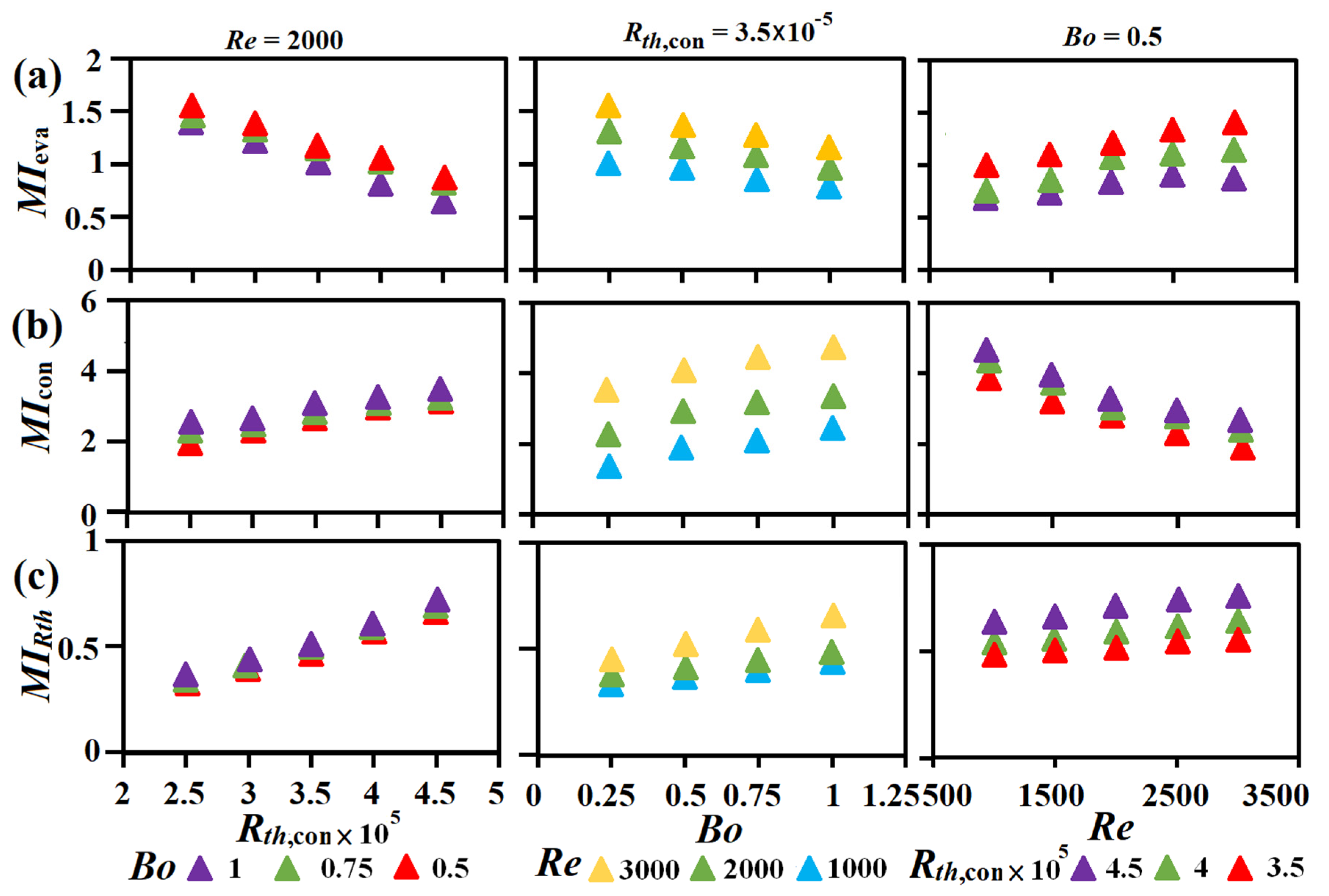
For highlighting the comparative hydrothermal performances between the pumped thermosyphon loops with ETC and TFC at component and system levels, the following merit indices are firstly proposed to quantify the performances of heat transmissions in evaporator (MIeva), in condenser (MIcon) and around the entire loop (MIRth) as Equations (8)–(10).
where CCOP in Equation (9) is the condenser coefficient of performance calculated from the enthalpy drop (Δhcon) at a mass flow rate () of refrigerant and the airflow pressure drop (ΔPcon) at a volume airflow rate () through the condenser to quantify the ratio between its convective thermal power and pumping power of airflow as Equation (11).
In Equations (9) and (10), PPeva the PPloop are the pressure drops of refrigerant through the evaporator and the entire loop which are, respectively, required to overcome the flow resistances through the evaporator and around the loop for sustaining a flow rate to generate Nueva and Rth. Following the definitions of MIeva, MIcon, and MIRth in Equations (8)–(10), the improved hydrothermal performance of the evaporator, condenser, or entire loop with ETC from that with TFC develops when MIeva > 1, MIcon > 1, and MIRth < 1. The strategic aim is to explore the isolated and interdependent effects of Bo, Rth,cond, and Re on the comparative performances of Nueav, Nucon, Rth, MIeva, MIcon, and MIRth between the pumped thermosyphon loops with TFC and ETC. The long-term unnoticed hydrothermal impacts of condenser configuration on the heat transfer performance of a pumped thermosyphon loop are also highlighted.
2.2. Facilities
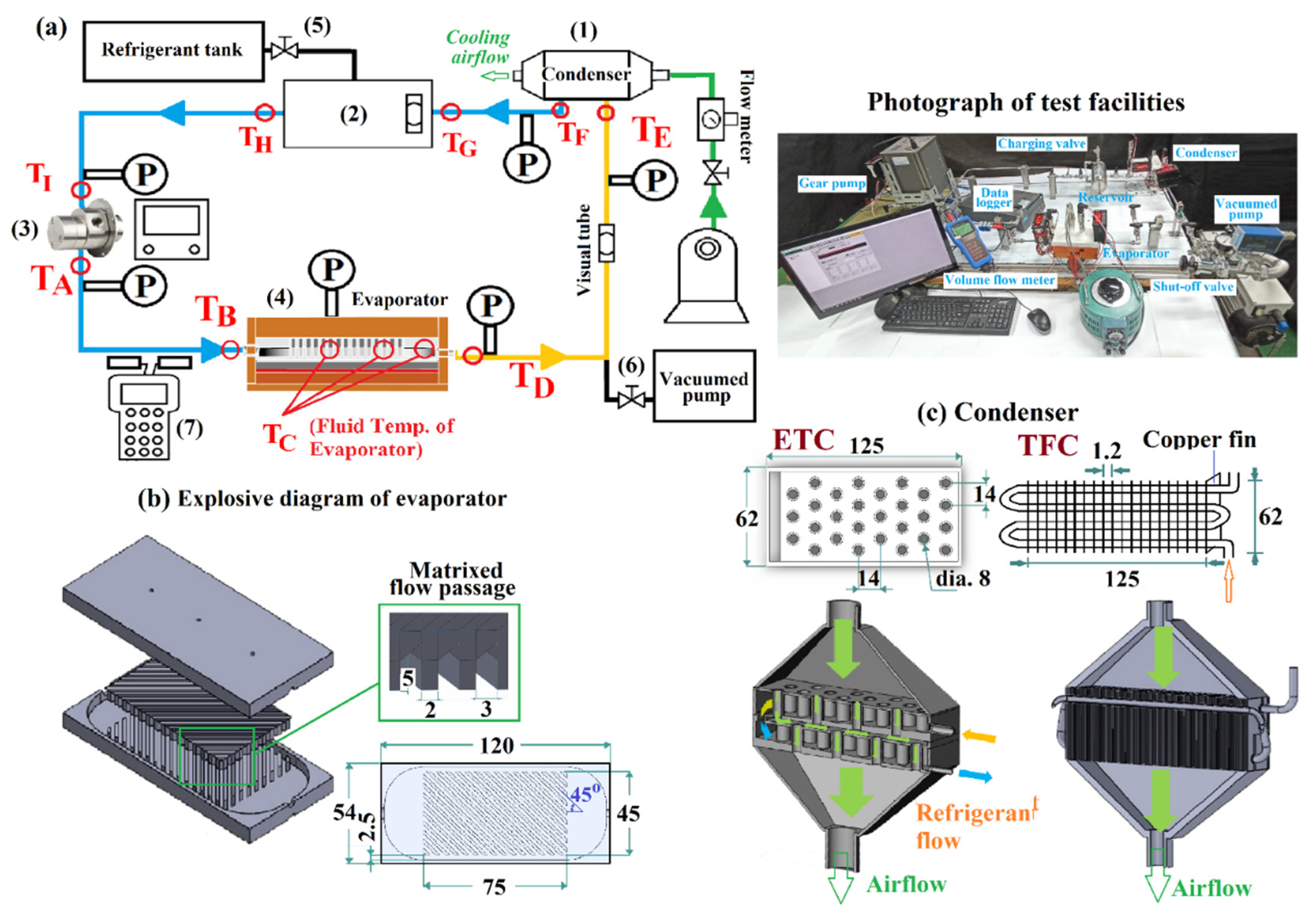
The experimental facilities are illustrated by Figure 1a in which the pumped thermosyphon loop and the configurations of ETC, TFC, and evaporator are depicted. Along with the schematics of test facilities, the photo depiction of the experimental setup and equipment is also included in Figure 1. The horizontal thermosyphon loop was composed by (1) condenser (ETC or TFC), (2) saturated liquid reservoir, (3) Fluid-O-Tech MG213 magnetically driven gear pump, and (4) evaporator. The entire thermosyphon loop was wrapped by thermal insulation layers to minimize the external heat loss. The total heating power fed to the evaporator was mostly transferred by the airflow through the condenser.
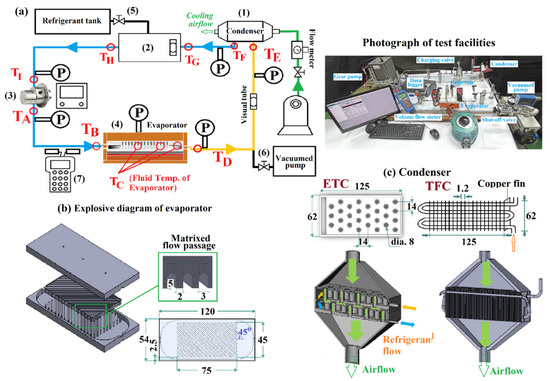
Figure 1.
(a) pumped thermosyphon loop (1) condenser (2) saturated liquid reservoir (3) Fluid-O-Tech MG213 magnet drive gear pump (4) evaporator (5) charging valve (6) shut-off valve (7) Redstar UFT010-P ultrasonic volume flow meter. (b) explosive diagram of evaporator (c) condenser.
While the interior configurations of condensers between TFC and ETC are different as compared by Figure 1, the identical core volume of 125 × 62 × 40 mm3 for ETC and TFC was embedded in a thermally insulated shield to facilitate the airflow cooling. As indicated in Figure 1, the dehumidified air supplied from a rotary compressor in an air tank was regulated and metered by a needle valve and a mass flow meter, respectively. The adjustment of cooling airflow rate regulated the refrigerant entry temperature of the condenser for maintaining the thermal resistance of condenser (rth,con or Rth,con) at a targeting value. The cooling power consumption was determined from the entry-to-exit pressure difference and the volume flow rate of the airflow through the condenser, which were, respectively, detected by a digital-type micro-manometer and a volume flow meter. The pressure drop across the condenser was measured to calculate the pumping power loss of the refrigerant flow through the condenser section. The pressure difference between the entry and exit of the pump was measured to evaluate the pumping power consumed for facilitating the total refrigerant flow around the loop.
To permit the energy-balance check between the thermal powers fed into the evaporator and transferred out of the condenser, the enthalpy increase of the cooling airflow through the condenser was evaluated. The thermocouples were located in the entry and exit air plenums of each condenser. Considering the non-uniform distribution of exit air temperature, five thermocouples were installed in the exit air plenum of each condenser. The five thermocouple measurements were averaged as the airflow exit temperature. The enthalpy increase of the airflow through the condenser was evaluated from the entry-to-exit air temperature increase, airflow rate and constant-pressure specific heat of air. As reported in previous section, the discrepancies between the cooling power of the airflow and the net convective thermal power (Q) of the evaporator were less than ±5.5%.
The copper made evaporator (4) adopted the matrix cooling scheme that was often applied to the trailing edge cooling of a gas turbine blade [34]. The evaporator (4) with the volume of 120 × 54 × 8 mm3 was composed by two ribbed plates with two vapor channels aside the evaporator sidewalls as shown by Figure 1b. In the matrix cooling passages of the evaporator, the refrigerant flowed through a large number of sharp bends to induce regional swirls and boost turbulent activities to promote heat transfer [34]. In addition, the flow pathway was considerably elongated along the matrix coolant pathways in the evaporator. The vapor bubbles generated in the matrix pathways were drifting among the convective flow to enter the two vapor confluent channels aside the two sidewalls of the evaporator. These vapor chanenls guided the vapor into the exit vapor chamber and then the exit pipe of evaporator. As indicated in Figure 1, the square rib with a rib height of 5 mm on the upper and bottom walls of the evaporator was oppositely orientated with an attack angle of 45 degs. The rib pitch was 3 mm, providing the rib pitch-to-height ratio of 0.6. In the evaporator, there was no gap between the upper and lower rib floors. It was worth noting that the saturated liquid reservoir (2) in the loop not only segregated the liquid and vapor phases upstream the pump; it also accommodated the various flow rates at different heating powers. Hence there was no compensation chamber in the evaporator (4).
In Figure 1c, the four-pass copper tubes with an inner diameter (d) of 4 mm, which was the characteristic length, were interconnected by three 180° bends and one elbow bend with an identical bending radius of 25 mm. Eighty-five copper fin plates with equal intervals were soldered on the serpentine tube to compose the TFC. The dimension of each copper fin was 58 × 41 × 0.3 mm3, providing the cooling area of 0.458 m2 in touch with the airflow. With the ETC made of stainless steel, there were eight rows of airflow tubes penetrating through the two-layer condensation chamber. The refrigerant vapor was suddenly expanded upon entering the upper chamber of the ETC. The staggered airflow tubes with an inner diameter of 8 mm were arranged with a spanwise pitch of 14 mm. The total cooling area of airflow in the ETC was 0.00852 m2, giving rise the airflow cooling area ratio between TFC and ETC as 54. The different interior configurations between TFC and ETC for refrigerant flow resulted in the different interfacial structures during vapor-to-liquid transition through the condenser. With the TFC, the formation of intermittent Taylor/Churn vapor bubbles in the saturated regime added both frictional and form drags along the tubular flow pathway. In the ETC, the frictional drags of liquid films along the bottom walls of the two condenser chambers dominated the flow resistance with lesser form drags resulting from the movements of vapor bubbles. In the ETC, the condensate emerged on the outer surface of each airflow tube was swept by the vapor cross flow with a thinner film thickness over the leading edge of the vertical airflow tube. A layer of liquid film was accumulated at the bottom wall of each vapor chamber in the ETC. These chamber bottom walls were machined with a slope of 1/12 to improve the fluency of the liquid film flow along the two bottom walls of the upper and lower vapor chambers. The different vapor-liquid flow structures in TFC and ETC resulted in the differential Nucon characteristics, which will be later illustrated. Nevertheless, although the cooling area in touch with airflow for the TFC was significantly larger than that in ETC, all the airflow areas in ETC were utilized to directly convert the latent heat released by the refrigerant vapor via a small conductive thermal resistance through the thin wall of airflow tube. The considerable conductive thermal resistance over each fin undermined the cooling effectiveness of TFC. The augmented resistance of refrigerant flow along with the large conductive thermal resistance for the airflow deteriorated the hydrothermal performance of TFC and added the flow resistance of the entire loop to raise the operating pressures. Particularly, the refrigerant flow area of 28,148 mm2 in ETC exceeded that of 6521 mm2 in the TFC, giving the ETC-to-TFC refrigerant flow area ratio of 4.316. The increased refrigerant flow area in ETC was beneficial for augmenting the condensation power from the TFC counterpart.
For charging the refrigerant R245fa with a purity of 99.95% into the loop, a charging valve (5) was installed at the top of reservoir (2). Prior to the charging process, the loop was pressurized by dry air at a pressure of 5.5 bar and then hold for 48 h. Having assured the leakage free for the loop, the pressurized air was vented for a subsequent vacuuming process. A vacuum pump connected with a shut-off valve (6) was activated to evacuate the loop up to the pressure of 10−4 Pa. Both the vacuum pump and valve (6) were shut to check if the vacuum pressure can maintain for 48 h. Once the satisfactory vacuum condition was achieved, the charging process commenced. The connecting pipe between the refrigerant tank and the charging valve (5) was degassed and then the charging valve (5) was opened to charge the refrigerant into the vacuumed loop. Without activating the heater and the pump, the pressure signals from all the pressure transducers corresponded to the saturation pressures at the ambient temperature, suggesting the NCG (non-condensable gas) free. For ensuring the effective pumping action, the liquid level in the reservoir was higher than the suction head of pump at all the operating conditions. Nevertheless, the liquid level in the cylindrical reservoir was initially dropped when the pump was starring. Having developed the stable vapor-liquid flow in the loop after feeding the thermal power to the evaporator, the excess liquid was pushed back to the evaporator from the reservoir to slightly raise the initial liquid level. For each loop, the charged refrigerant volume was 75% of the entire loop volume including the total volume of reservoir. At all the test conditions, the liquid level in the reservoir was remained in the range about 0.7–0.8 reservoir height.
Three pairs of pressure transducers along the loop as indicated in Figure 1 measured the pressure increase through the pump, and the pressure drops through the evaporator and condenser. The volume flow rate of liquid refrigerant was detected by the Redstar UFT010-P ultrasonic volume flow meter (7). The two ultrasonic probes were installed around the 160 mm long straight tube downstream the condenser. The pumping power for facilitating the refrigerant flow through evaporator, condenser and entire loop were evaluated from the mass flow rate of refrigerant converting from the ultrasonic volume flow measurement.
In addition to the pressure measurements, 11 thermocouples were deployed to measure the refrigerant temperatures along the loop. The fluid temperature of evaporator (TC) was averaged from the three thermocouples that penetrated into the evaporator. Along with the pressure signals, the fluid temperatures of TA to TI were adopted to plot the thermodynamic cycle in pressure-temperature (P-T) and pressure-enthalpy (P-H) diagrams. For measuring the averaged heat transfer rates of evaporator and condenser, three pairs of thermocouples were embedded in the evaporator bottom walls and the condenser tube wall to measure Tw,eva, and Tw,con. For detecting the overall thermal resistance of each loop, the heater temperature (THF) was measured by a thermocouple located at the central of the heater foil.
With a pump to drive the vapor-liquid circulation, the sub-cooled liquid entering the evaporator could leave at the superheated state. When Bo was above than unity, the coolant through the visual tube downstream the evaporator exhibited gaseous state and the evaporator was partially dry-out. Otherwise with Bo less than one, the refrigerant exited from evaporator as wet vapor. The sensible heat from subcooled liquid to saturated vapor in the evaporator was determined by the fluid temperature rise from the entry temperature of evaporator (Teva,in) to the saturation temperature at the evaporator pressure. For constructing the thermodynamic cycle with Bo less than unity, the dryness fraction of refrigerant at the evaporator exit (x) was calculated from the net heating power (Q), the mass flow rate of refrigerant (), the latent heat (hfg), and the constant-pressure specific heat of liquid (Cp,L) by Equation (12).
The sensible heat from subcooled to saturated states was less than 8% of hfg so that the x value was close to Bo when Bo was less than unity. The variations of P-T and P-H cycles caused by varying Re, Bo, and, or, Rth,cond revealed the loop’s responses to the adjustments in refrigerant flow rate, heating power, and, or, cooling duty.
2.3. Program
The experimental program was formulated to fulfill the strategy formulated by Equation (1) with the isolated impacts of Bo, Rth,cond, and Re on Rth, Nueva,con, and MIs examined for the two thermosyphon loops with TFC and ETC. The interdepend Bo, Rth,cond, and Re impacts on Rth, Nueva,con, and MIs were disclosed in the phase of parametric analysis aimed at devising the correlations of Nueva,con, and Rth. Four different heating powers in the range of 45–330 W were applied at a Reynolds number of 1000, 1500, 2000, or 2500. With the fixed Q and Re, four cooling airflow rates were supplied to TFC or ETC for regulating Rth,cond. The ranges of Bo and Rth,cond were 0.23–1.21 and 2 × 10⁻⁵–5 × 10⁻⁵ for the two pumped thermosyphon loops. As a practical advantage using a pumped thermosyphon loop, the Bo limit less than one for a wicked LHP that utilizes capillary forces to drive vapor-liquid circulation can be further extended. In other words, when the dry-out occurs in a capillary-force driven LHP to block off the circulation of working fluid, the pumped thermosyphon loop can still facilitate the vapor-liquid circulation. It is permissible to convert the sub-cooled liquid into the superheated vapor through the evaporator in a pumped thermosyphon loop. The evaporator of each loop with TFC or ETC was partially dry-out with 1 < Bo ≤ 1.21 at a steady state condition, otherwise the dryness fraction of the vapor at evaporator exit was less than one.
The inference of experimental uncertainties of Bo, Re, Rth,cond, Nueva, Nucond and Rth followed the method reported by Kline McClintock [35]. The error percentages of the instruments were estimated from the precisions and the data ranges of the raw measurements. The precisions of the measurements were referred to the calibration reports provided by the manufacturers. Table 1 summarizes the precisions of the instruments and their corresponding data ranges and error percentages.

Table 1.
Estimation of error percentages for the instruments measuring raw data.
The fluid properties, kL and μ, latent heat (hfg), and saturated temperatures in evaporator and condenser at the measured evaporator/condenser pressures were calculated by the correlations derived from the tables using Tsat or P as the determining variable. As the discrepancies between the correlation results and the table values are negligible, the maximum uncertainties of kL, μ, and hfg were inherited from the error percentages of Tsat, which were originated from the precision errors of Peva/con measurements. In this regard, the maximum uncertainties of kL, μ, hfg, and Tsat were 0.5%, 2.3%, 0.7%, and 1.5%, respectively. With the manufacturing tolerance of ± 0.01 mm, the percentage error of d was 1.4%. The range of fell in the ranges of 0.0007–0.0021 kgs−1. The maximum uncertainties of Nu, Re, Bo, Rth,con, and Rth are ±3.6%, ±4.3%, ±8.3%, ±3.73% and ±6.17%, respectively.
3. Results and Discussion
3.1. Comparison between Loops with TFC and ETC at System Level
3.1.1. Test Pressures and Saturated Temperatures of Evaporator and Condenser
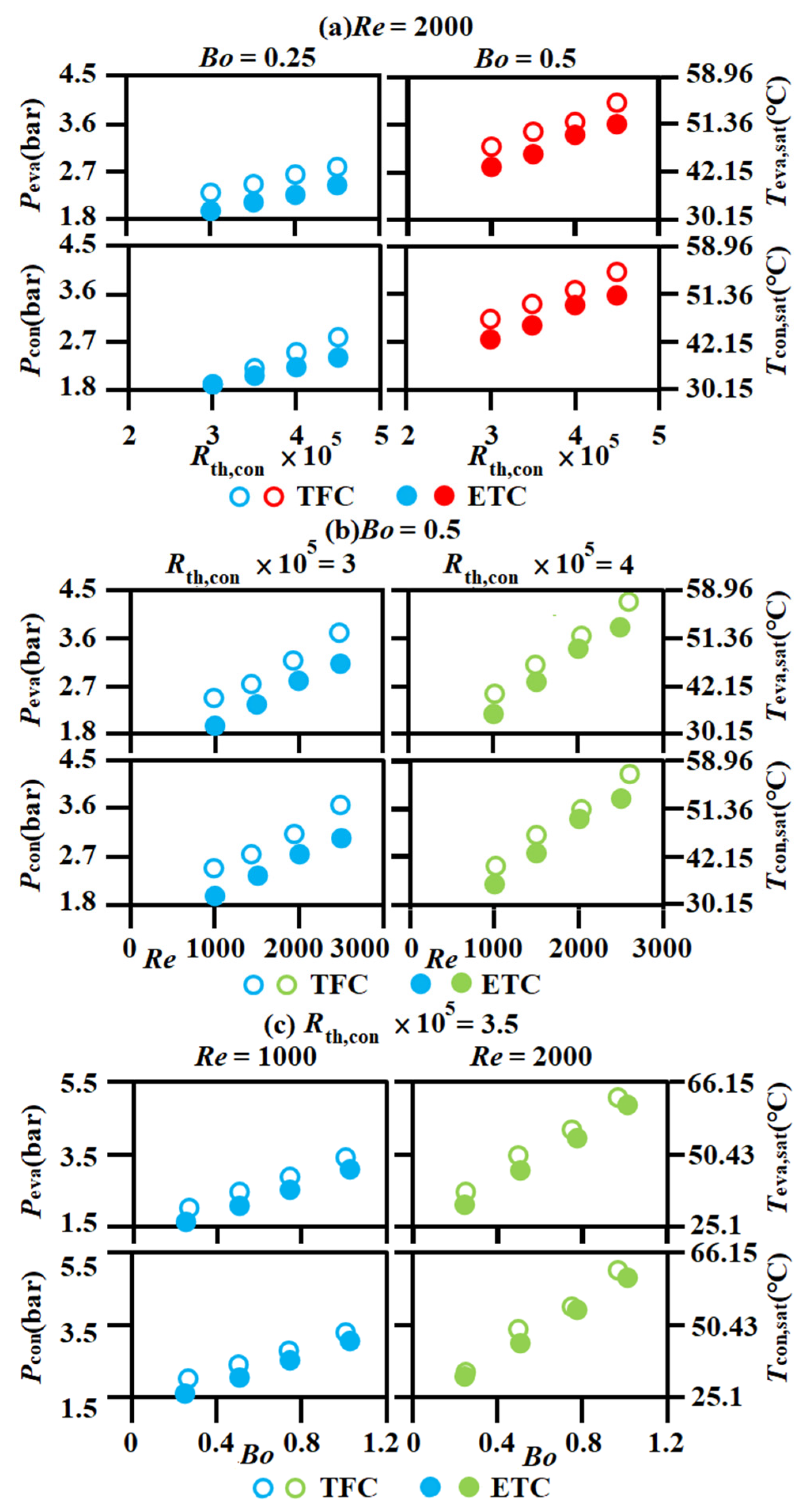
Prior to comparing the various thermal performance indices between the two thermosyphon loops with TFC and ETC, the variations of Peva,con and Teva,con,sat against (a) Rth,con at Re = 2000 (b) Re at Bo = 0.5 (c) Bo at Rth,con = 3.5 × 10⁻⁵ for the two thermosyphon loops shown by Figure 2 are examined to exemplify the influences of Rth,con, Re, and Bo on the saturated pressures and temperatures in evaporator and condenser. For providing a clear view of comparison between the loops with TFC and ETC, the data ranges for constructing the plots in Figure 2 are different. In each plot of Figure 2, all the Peva,con and hence Teva,con,sat are increased along with Rth,con, Bo, or Re when the other two parameters remain fixed. As illustrated in previous section, the increase of Rth,con is achieved by reducing the cooling airflow rate that raises the operating temperatures along the entire loop. When the working fluid is undergoing the phase change heating (cooling) process in the evaporator (condenser), the elevated temperature has led to the attendant increase of saturated pressure. By way of Re increase to augment the flow resistance along each thermosyphon loop, the driven pressure head of the pump is accordingly increased to raise the loop pressures, leading to the increases of Peva,con and Teva,con,sat in Figure 2b. At a fixed Re (refrigerant mass flow rate), the dryness fraction calculated by Equation (12) deems to increase with Bo (heating power). In a plate heat exchanger with crossed angle-ribs on two opposite endwalls of a narrow channel, Hsieh and Lin [36] reported that both the evaporation heat transfer rate and pressure drop increased with the vapor quality. Owing to the raised pressure drop through the present evaporator after elevating heating power (Bo) at a fixed Re, the exit pressure of pump is accordingly increased to cope with the added flow resistance in the loop. Thus, Peva,con and hence Teva,con,sat keep increasing with Bo in Figure 2c.
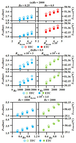
Figure 2.
Variations of Peva,con and Teva,con, sat against (a) Rth,con at Re = 2000 (b) Re at Bo = 0.5. (c) Bo at Rth,con = 3.5 × 10⁻⁵ for the thermosyphon loops with TFC and ETC.
While the similar data trends caused by varying Rth,con, Bo, or Re are observed for the loops with TFC and ETC, the loop with TFC constantly operates at a higher Peva,con (Teva,sat) than that with ETC at the similar Rth,con, Re, and Bo. Such comparative Peva,con (Teva,con,sat) difference in each plot of Figure 2 enlightens the significance of condenser configuration on the saturated pressures in the evaporator and condenser of a pumped thermosyphon loop. Considering the interior configurations of TFC and ETC, the form and frictional drags formulated by the vapor bubbles moving along the condenser tube of TFC exceeded that in ETC, which will be later demonstrated. Acting by the larger flow resistances in the loop with TFC, the higher exit pressure of pump and hence Peva,con are generated for sustaining a similar refrigerant flow rate at a Re. At system level, the increased Teva,sat due to the elevated Peva,con raises THF and hence Rth (rth) even if the average Nueva remains unchanged. The configuration of a condenser, which affects the induced flow resistance, hence plays an important role to affect the overall thermal resistance of a pumped thermosyphon loop.
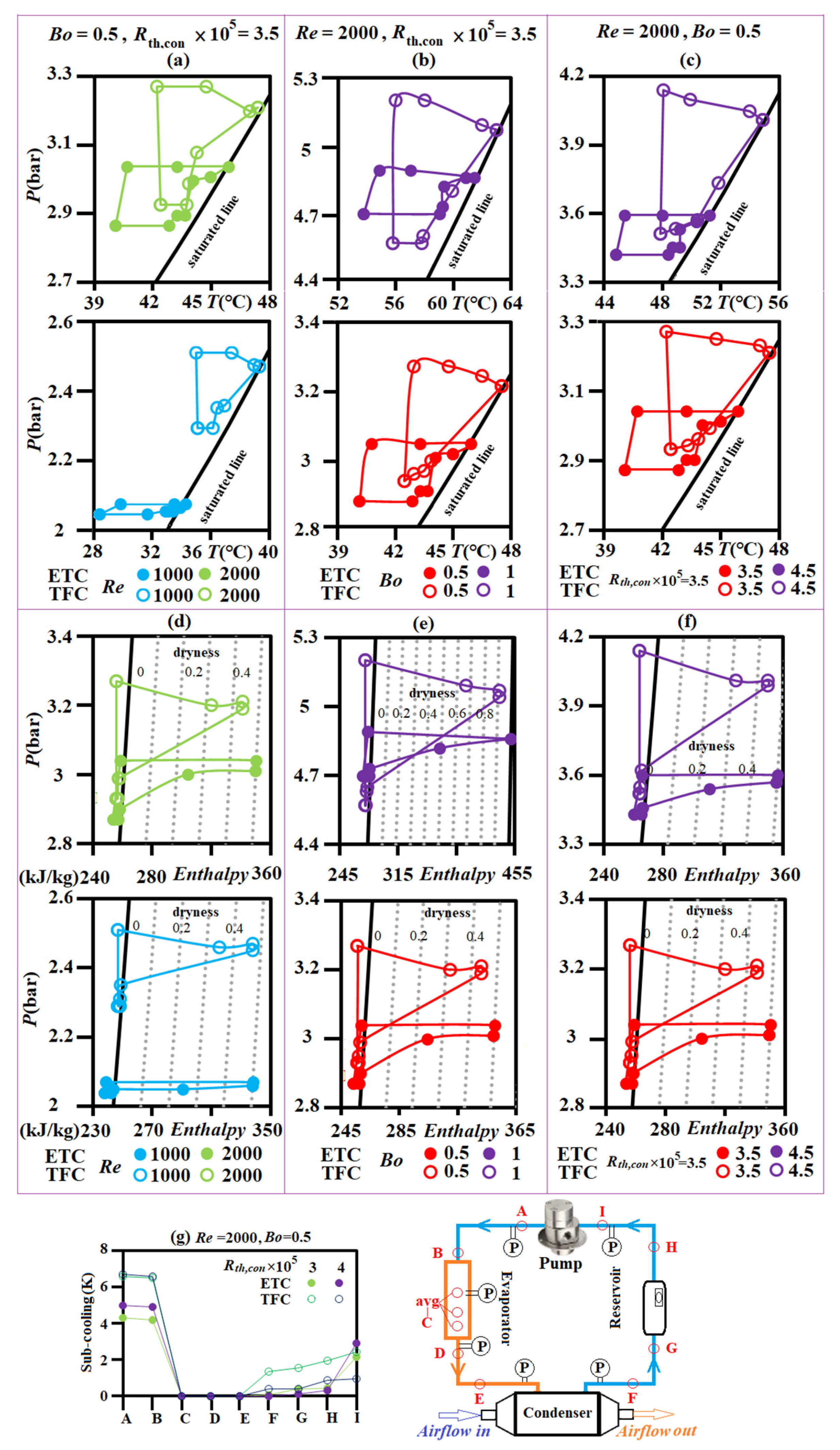
The considerable impacts of Bo, Rth,con, and Re on Peva,con and Tsat,eva,con have been demonstrated by Figure 2 for the two pumped thermosyphon loops. The vapor-liquid interfacial structures in evaporator and condenser are, respectively, affected by the superheated degree and the sub-cooling temperature that vary with operating pressures and hence Bo, Rth,con, and, or, Re. In this regard, the vapor-liquid dynamics in the evaporator and condenser are mostly affected by Bo (superheated degree) and the interior structure of the condenser, respectively. Therefore, the thermodynamic cycles in P-T and P-H diagrams are different between the loops with TFC and ETC, which are Bo, Rth,con, Re dependent. Figure 3 depicts the isolated influences of (a,d) Re, (b,e) Bo (c,f) Rth,con on the measured P-T and P-H cycles for the loops with TFC and ETC. The A to I locations along each loop with the temperature measurements TA to TI are correspondingly marked on the thermodynamic cycles in Figure 3. The evaporator fluid temperature (TC) is averaged from the three thermocouple readings in the evaporator. While the liquid and vapor lines are merged into a saturation line in a P-T diagram, the horizontal temperature span from the maximum cycle temperature (TD) to an airflow temperature (T∞), which varies between 24–25 °C, reflects the higher overall thermal resistance (Rth, rth) with the larger TD-to-T∞ span. The vertical pressure span of a P-T cycle quantifies the total pressure drop of the loop, which is equal to the pressure increase through the pump.
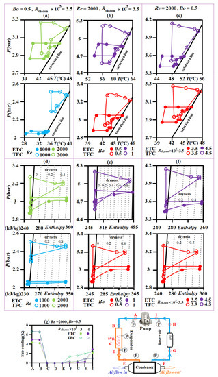
Figure 3.
Thermodynamic cycles of the pumped thermosyphon loops with TFC and ETC in P-T and P-H diagrams for revealing the isolated impacts of (a,d) Re, (b,e) Bo (c,f) Rth,con. (g) sub-cooling temperatures along loops at Re = 2000, Bo = 0.5 with Rth,con = 4 × 10⁻⁵ and 3 × 10⁻⁵.
3.1.2. P-T and P-H Cycles
Figure 3a–f feature the isolated impacts of Re, Bo, and Rth,con on the P-T and P-H cycles, respectively. In this regard, the increase of Re, Bo, or Rth,con drives the P-T and P-H cycles upward along the saturation liquid line on its own right. In Figure 3a,d, the increase of Re from 1000 to 2000 noticeably extends the A-to-B pressure rise for the P-T and P-H cycles, indicating the enlarged pressure drop across each loop due to the increased flow resistance by raising the flow rate of refrigerant. While the A-to-B pressure elevation across the pump is sensitive to the variation of Re, the increase of Bo from 0.5 to 1 extends the maximum-to-minimum temperature span for each P-T or P-H cycle with TFC or ETC in Figure 3b,e. In [37], Park and Hrnjak found that the pressure drop of condensation CO2 flow in multi-port microchannels increased with the increase of mass flux and vapor quality, but with the decrease of saturation temperature. Such mass-flux and vapor-quality impacts on the condensation pressure drop are similarly applied to the enlarged E-to-F pressure drop across the present TFC and ETC. As shown by Figure 3a,b,e, the extensions of E-to-F pressure drop driven by increasing Re (mass flux) and Bo (dryness fraction) are evident. In addition, the comparisons of P-T and P-H cycles in all the plots of Figure 3 reveal that the E-to-F pressure drop across the TFC is consistently larger than ETC at the similar test condition. Kim reported that both the condensation heat transfer rate and the pressure drop of R-410A in multi-port tubes increased when the hydraulic diameter of tube was decreased [38]. The condensation physics responsive to the larger pressure drop in the tube with a smaller hydraulic diameter [38] extend the E-to-F pressure drop across TFC from that in ETC. As the B-to-D pressured drop across evaporator is generally less than the E-to-F pressure drop across condenser for both the TFC and ETC loops, the pressure drop over the entire loop is dominant by the flow resistance developed in the condenser. The responses of I-to-A pressure increase, which is raised by the pump, to the Re, Bo, or Rth,con variations hence follow the varying pattern of E-to-F pressure drop across the condenser in Figure 3.
It is interesting to find that the increase of Rth,con from 3.5 × 10⁵ to 4.5 × 10⁵ incurs a considerable extension of I-to-A pressure difference for the loop with TFC but exhibits a moderate impact on the I-to-A pressure increase for the loop with ETC as compared by Figure 3c,f. Following the previous illustrations, the enlarged I-to-A pressure drop owing to the increase of Rth,con for the entire loop with TFC is mainly caused by the increase of the pressure drop across the condenser. This result suggests that the flow resistances in TFC are considerably increased by reducing the cooling airflow rate when Rth,con is increased at constant Re and Bo. When Rth,con is increased, Pcon and Tsat,con are increased and the heat transfer rate of cooling airflow is reduced; but the airflow temperatures through the TFC are elevated at a fixed Bo. The combined effect has led to the extension of the vapor-to-liquid transition length along the serpentine tube of present TFC to boost the pressure drop of the refrigerant flow through the TFC. Nevertheless, with the interior configuration of ETC, the likewise extension of the vapor-to-liquid transition length along with Rth,con is not developed in the ETC so that the pressure drop across the ETC and hence its entire loop is not noticeably increased by raising Rth,con.
As compared by Figure 3a–c for highlighting the differential P-T cycles between the loops with TFC and ETC, the higher Peva for the loop with TFC has led to the higher TD and consequently extended the TD-to-T∞ temperature span from the ETC counterpart. However, the maximum-to-minimum temperature spans for the P-T cycles with TFC and ETC in Figure 3a–c remain similar at each set of Bo, Rth,con, and Re. With R245fa as working fluid, the reduced pressure from spot F (condenser exit) to location I (pump entry) incurs a further TF-to-TI temperature drop as indicated by the P-T cycles in Figure 3a–c. In addition to the flow resistance encountered along the pipeline between locations F and I, the pressure head of the reservoir further enlarges the F-to-I pressure difference. However, owing to the higher pressure drop across the TFC, the lesser vertical pressure span PA-to-PI for the cycle with ETC is constantly observed in Figure 3a–c. While the larger pressure drop for the loop with TFC is affirmed, a common feature shared by the two loops with TFC and ETC is the higher pressure drop across the condenser than that through the evaporator. Owing to the higher momentum change of the working fluid during which the vapor is condensed into liquid in TFC or ETC, the pressure drop in the condenser exceeds that in the evaporator. For each pumped thermosyphon loop with TFC or ETC, the pressure drop across the condenser hence plays a dominant role in composing the entire pressure drop of the loop.
In the P-H diagrams shown by Figure 3d–f, the B-to-D enthalpy increase through evaporator is similar to the E-to-F enthalpy drop across condenser for each cycle to reassure the energy balance condition. Nevertheless, as hfg is reduced by increasing Peva, the lesser heating power is supplied to the loop with TFC, which is operating at a higher pressure, with a fixed Bo. Consequently, the enthalpy increase (decrease) through the evaporator (condenser) for the loop with ETC is slightly higher than that with TFC as compared in Figure 3d–f. The dryness factors at the evaporator exit for the loop with ETC are correspondingly increased from that with TFC. When the latent heat is released in condenser, the different interior configurations between TFC and ETC induce different pressure drops for such a vapor-to-liquid transition process. The pressure drop accompanying with the enthalpy decrease during the vapor-to-liquid transition across the TFC is considerably larger than that with ETC at similar Bo, Rth,con, and Re, leading to the different vapor-liquid dynamics and hence Nucon between TFC and ETC, which will be later illustrated.
As compared by Figure 3g, the sub-cooling temperatures along the loop with ETC are generally less than that with TFC at the similar Re, Bo, and Rth,con, indicating a better temperature uniformity and hence cooling efficiency with ETC. While the sub-cooling degrees downstream ETC at locations F and G in Figure 3g are negligible at the particular test condition, the larger airflow rate for maintain TFC at a similar Rth,con raises the sub-cooling degrees downstream TFC. The large conductive thermal resistance between the fins and the serpentine tube of TFC incurs a considerable streamwise temperature gradient along the tubular refrigerant flow passage. Downstream the reservoir prior to the pump entry at locations H and I, the sub-cooling temperatures are noticeably increased for both loops due to the suction head generated at the pump entry that reduces the saturation temperature of refrigerant. Such augmented sub-cooling effect is beneficial for preventing cavitation in pump. With the work input to the pump, TA at pump exit is slightly increased from TI at pump inlet for each P-T cycle in Figure 3a–c due to the entropy increase for pressurizing the liquid flow. Nevertheless, the increased saturate temperature accompanying with the raised pressure by the pump exceeds the fluid temperature increase owing to the attendant work input. The sub-cooling degrees at A, B locations in Figure 3g are larger than that at location I (pump entry). At the immediate entry of evaporator (location B), the sub-cooling degrees are ranging between 4.6–5.8 K and 6.1–6.8 K for the loops with ETC and TFC, respectively. These sub-cooling degrees are sufficient to avoid the coolant flushing upon entering the evaporator. When Rth,con is reduced from 4 × 10⁻⁵ to 3 × 10⁻⁵ by increasing the cooling airflow rate through the condenser, the sub-cooling effects are extended for both loops with TFC and ETC. Above all, the elevated maximum cycle temperature owing to the large pressure drop across TFC not only significantly increases Rth of the loop, but also elevates the sub-cooling degrees to add the pumping power for facilitating the required airflow rate at a set of Re, Bo, and Rth,con. The quantitative assessment in this regard is undertaken by comparing the merit index MIcon as later illustrated.
3.2. Heat Transfer Characteristics
3.2.1. Evaporator Heat Transfer
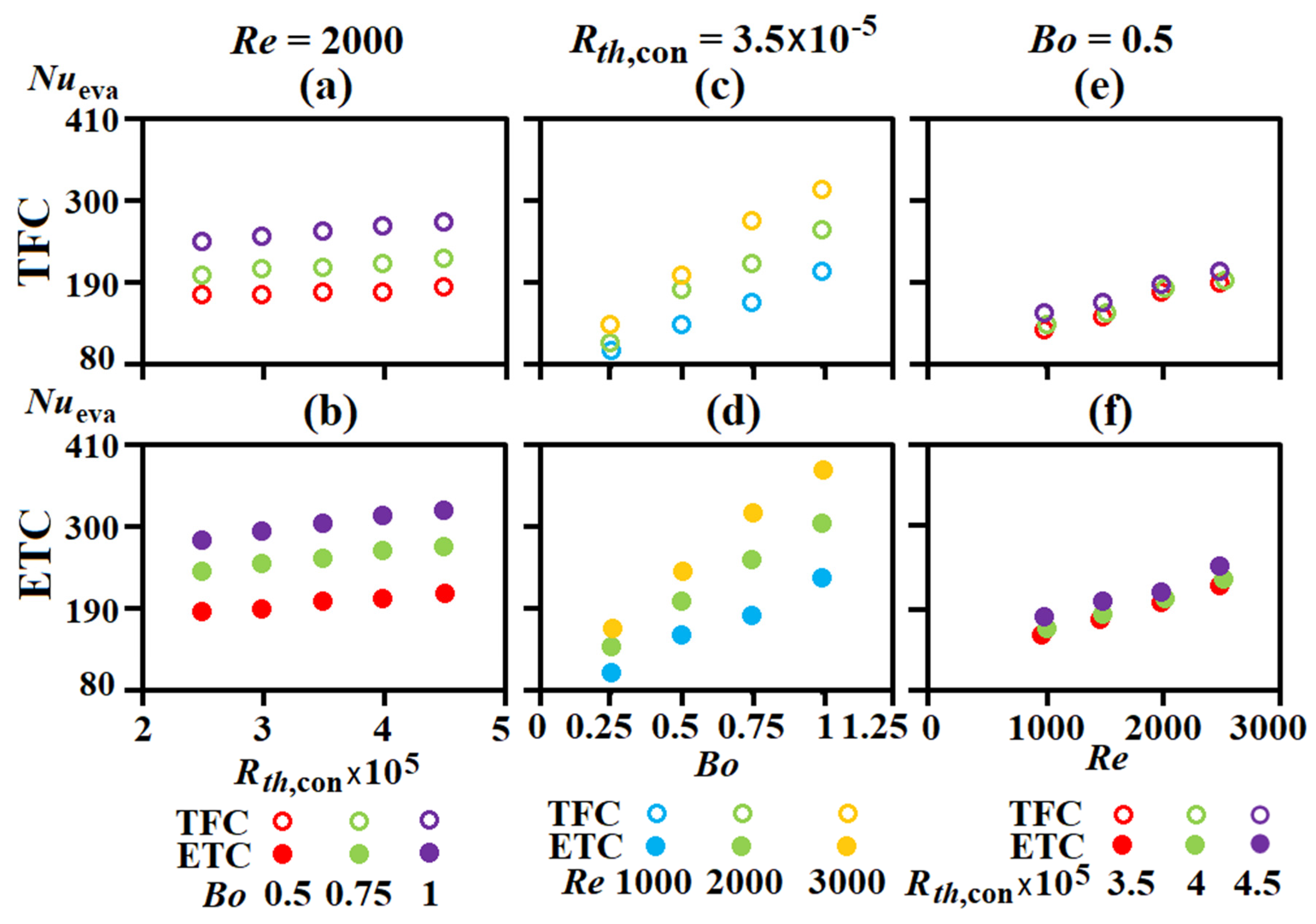
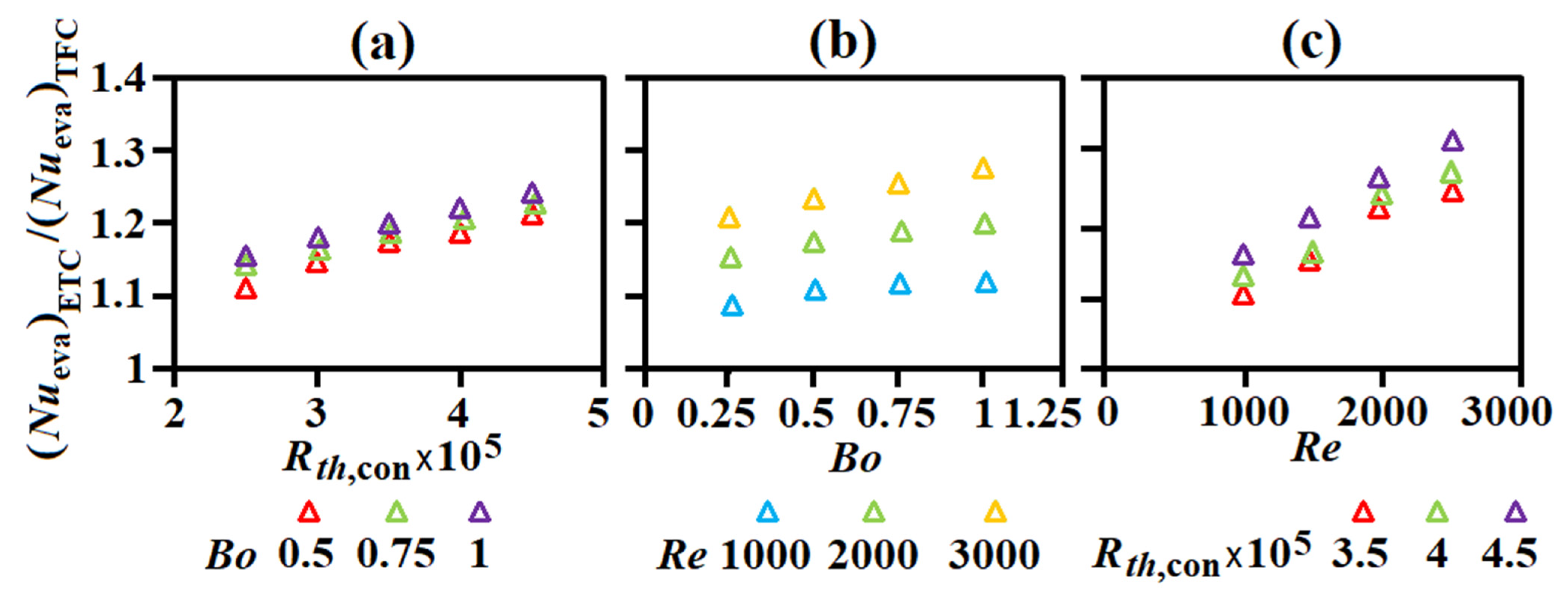
The changes of flow and vapor-liquid structures in the evaporator to respond the adjustments of Re, Bo, and, or, Rth,con result in the attendant Nueva variations. The different Peva and Teva,sat variations against Re, Bo, and Rth,con between the loops with TFC and ETC as typified by Figure 2 serve as the main physic to differentiate the vapor-liquid flow patterns and hence Nueva in the evaporators at a similar set of Re, Bo, and Rth,con. Figure 4 compares the variations of Nueva against (a,b) Rth,con at Re = 2000 (c,d) Bo at Rth,con = 3.5 × 10⁻⁵ (e,f) Re at Bo = 0.5 between the loops with TFC and ETC, respectively.
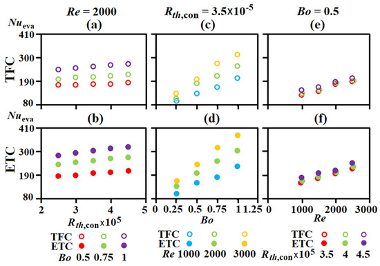
Figure 4.
Variations of Nueva along with (a,b) Rth,con at Re = 2000 (c,d) Bo at Rth,con = 3.5 × 10⁻⁵ (e,f) Re at Bo = 0.5 between the loops with TFC and ETC. The ratio of Nueva between the loops with ETC and TFC against (a) Re, (b) Bo, (c) Rth,con in Figure 5.
For both loops, the increase of Rth,con and Bo with the other two parameters unchanged raises the superheats. The increase of superheat at the flow boiling regime prior to generating a vapor film over the boiling surface generally improves heat transfer so that the Nueva data are consistently increased along with Rth,con and Bo for both loops as shown by Figure 4a–d. By raising the flow velocity through the evaporator to promote the departure of vapor bubbles from the boiling surface and the heat transfer mechanisms associated with the increase of Re, such as the augmentations of turbulence and mass transfer, the Nueva levels keep increasing along with Re in Figure 4e,f. As the loop with TFC constantly operates at a higher Peva than that with ETC loop at a similar set of Re, Bo, and Rth,con, the higher vapor density in the evaporator of the loop with TFC is expected. Bang et al. [39] explored the effect of pressure on the water flow boiling heat transfer and found that the effect of pressure on the flow boiling heat transfer exhibited as a counter-affecting phenomenon between vapor density, liquid viscosity and liquid thermal conductivity. In this respect, the higher vapor density at the higher pressure weakened the vapor momentum and hence thickened the liquid film, leading to heat transfer impediments. On the contrary, the lower liquid viscosity along with higher liquid thermal conductivity at the lower pressure promoted heat transfer rates. The counteracting effects associated with the increased pressure was concluded to suppress the boiling flow heat transfer. Following the pressure effect on the flow boiling [39], the Nueva for the loop with ETC are consistently higher than the TFC counterparts so that the Nueva ratios between the loops with ETC and TFC exceed unity as shown by Figure 4g–i.
In view of flow boiling through a corrugated channel, Rossato et al. [40] measured the flow boiling heat transfer rates of R32 though a plate heat exchanger. The flow boiling heat transfer rates were affected by both nucleate boiling and forced convective boiling mechanisms. The Cooper correlation that evaluates the heat flow rate in saturated nucleate boiling pool coherently underestimates their flow boiling results, whereas the correlations that integrated nucleate boiling with forced convection exhibited a better performance [40]. In a plate heat exchanger with R-134a flowing through a narrow channel with a corrugated sine shape of a chevron angle of 60 deg. in a counter-flow scenario, the boiling heat transfer rate was much higher than that in circular tubes owing to the intense boiling activities on the corrugated surface [41]. Particularly, the data of Yan and Lin [41] showed that the boiling heat transfer rate was slightly lower at a higher refrigerant pressure. Clearly, the flow boiling heat transfer in the present evaporator with matrixed angled ribs is governed by the synergic nucleate boiling and forced convective flow. The intensified boiling activities on the ribbed surface with the boiling heat transfer rate to be slightly reduced at a higher refrigerant pressure [41] are expected. In view of the data trends collected in Figure 4, the increasing trends of Nueva with Rth,con, Bo or Re are the reflections of the raised Peva shown by Figure 2 to respond the typical pressure effect in Cooper correlation for nucleate pool boiling. However, the lower Nueva with TFC at a higher Peva as compared by Figure 4 is a result of the forced convective phenomenon for flow boiling through a corrugated channel [41]. As the Nueva with ETC exceeds that with TFC in each plot of Figure 4, the convective flow mechanism dominates the synergic nucleate boiling with forced convection in the present evaporator roughened by the matrixed angle ribs.
In Figure 5a–c, the ratios of Nueva between the loops with ETC and TFC are depicted to quantify the isolated Re, Bo, and Rth,con impacts on the Nueva for the ETC and TFC loops. Following the heat transfer results depicted in Figure 4, the ETC-to-TFC Nueva ratios are in the range of 1.09–1.35 for the entire Nueva data generated. By increasing Re, Bo, and, or, Rth,con, the ETC-to-TFC Nueva ratios are further elevated, indicating the enlarged pressure effect on the differential Nueva results between the loops with ETC and TFC.
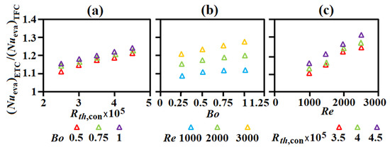
Figure 5.
The ratio of Nueva between the loops with ETC and TFC against (a) Re, (b) Bo, (c) Rth,con.
3.2.2. Condenser Heat Transfer
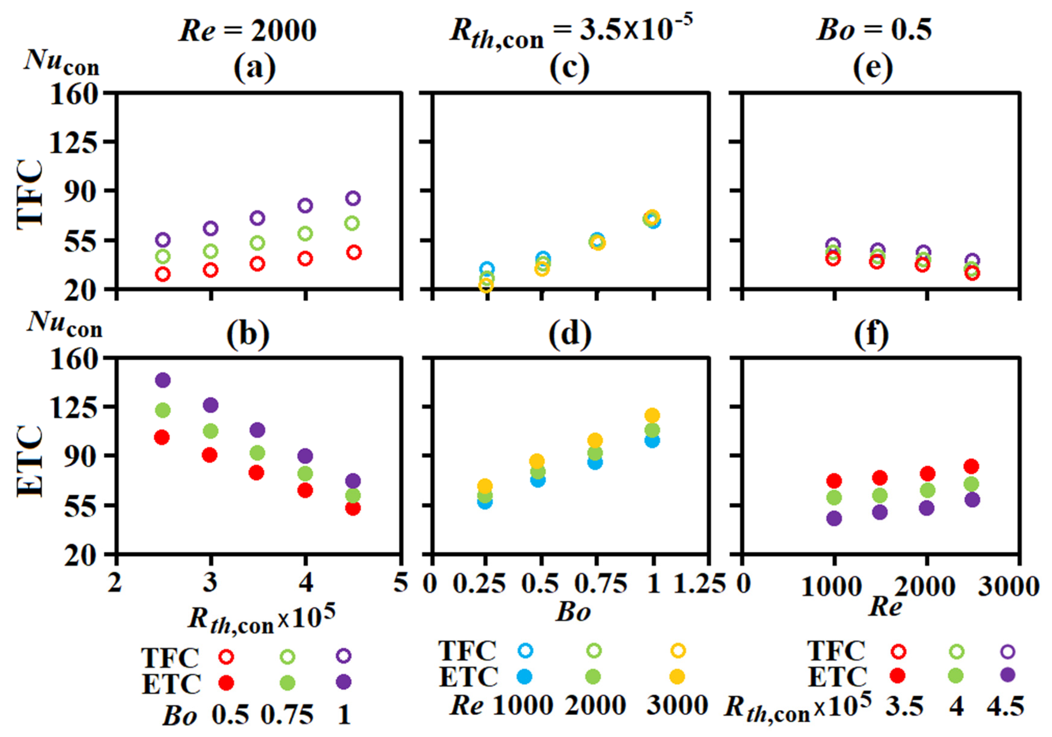
The various interior configurations between TFC and ETC resulted in the different patterns of Nucon variations against Rth,con, Bo, and Re as, respectively, depicted by Figure 6 a,b at Re = 2000, c,d at Rth,con = 3.5 × 10⁻⁵, and (e,f) at Bo = 0.5. In contrast with the similar trends of Nueva variation driven by increasing Rth,con, Bo or Re for the loops with TFC and ETC seen in Figure 4, the varying trends of Nucon against Rth,con and Re for the loops with TFC and ETC are reversed; whereas the patterns of Bo-driven Nucon variation for TFC and ETC loops are similar. This is demonstrated by comparing Figure 6a–f. In the present TFC and ETC, the condensation processes are, respectively, taking place inside the serpentine tube and outside the tube banks. While the dryness fraction in a condensation tube dominates its heat transfer rate for TFC, the inundation phenomenon among the tube bank and the film thickness attached on the outer surface of each tube under a cross vapor flow are accounted for Nucon. In particular, the condensate flooding at the inclined bottom plates of ETC thickens the condensate film to increase the thermal resistance. This phenomenon often leads to a higher sub-cooling of the condensate to deteriorate the overall heat transfer performance of ETC. These flow mechanisms affected by varying Rth,con, Bo or Re affect the overall condensation heat transfer rates (Nucon) in TFC and ETC. As shown by Figure 6a–c, the in-tube dryness fraction is increased by increasing Rth,con and Bo, but reduced by increasing refrigerant flow rate (Re) at a fixed cooling duty (Bo) for TFC. As the in-tube condensation heat transfer rate is increased with dryness fraction, Nucon is elevated by increasing Rth,con and Bo, but reduced as Re increases. In present ETC, the flow mechanisms affecting Nucon are more complex, including vapor-to-wall temperature difference, dryness fraction, inundation, and film thickness under a cross vapor flow. Zhang et al. [42] found that the condensation heat transfer rates of HFC134a and CFC12 outside horizontal tubes of low thermal conductivity decreased with the increase of vapor-to-wall temperature difference. As Rth,con increases by reducing the cooling airflow rate through ETC, the vapor-to-wall temperature difference is accordingly increased to undermine the condensation heat transfer rates (Nucon) outside the tube rows in the ETC as demonstrated by Figure 6b. By way of Bo increase to raise overall dryness fraction in ETC, Nucon in ETC is accordingly increased in Figure 6d, which data trend agrees with the experimental result of Wang and Du [43]. When the momentum of cross vapor flow is enhanced by raising Re, the inundation effect is moderated and the film thickness is also reduced. As these beneficial effects outweigh the undesirable impact associated with the reduced dryness fraction, the Nucon in ETC turns to increase with Re in Figure 6f.
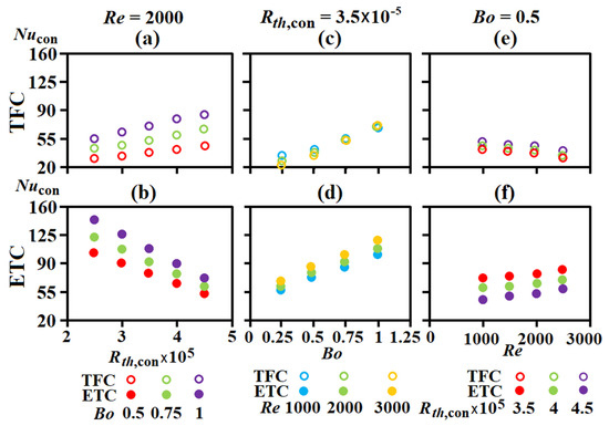
Figure 6.
Variations of Nucon along with (a,b) Rth,con at Re = 2000 (c,d) Bo at Rth,con = 3.5 × 10⁻⁵. (e,f) Re at Bo = 0.5 between the loops with TFC and ETC.
In addition to the aforementioned flow physics to different the Nucon results between TFC and ETC, the space ratios with phase-change activities in TFC and ETC also effect their overall Nucon results. In the TFC, the condensation process was confined in the serpentine tube to undergo the vapor-to-liquid phase transition, following the typical sequence of mist annular, annular, slug, plug, and subcooled flows [44]. As a condensation heat transfer rate was considerably higher than that with a subcooled liquid flow, the extension of the subcooled flow regime along the refrigerant tube in a TFC undermined the overall condensation heat transfer rate. The consequences of extended subcooled flow regime caused by reducing Rth,con, Bo, or by increasing Re along the TFC were reflected on the data trends of Nueva in Figure 6a,c,e, respectively. The increase of Rth,con by reducing cooling airflow rate, or the increase of dryness fraction at condenser entry by raising Bo shortened the portion of the subcooled liquid flow in the serpentine refrigerant tube of the TFC. As a result, the overall condensation heat transfer rate indexed by Nucon keeps increasing along with Rth,con, or Bo as seen in Figure 6a,c. With constant heating power and hence enthalpy drop through the TFC at a fixed Bo, the increase of refrigerant mass flow rate by raising Re shortened the length of the saturated vapor to extend the portion of the subcooled regime at a Rth,con with a specific cooling airflow rate. As a result, all the Nucon data shown in Figure 6e are reduced along with Re. Acting by the combined Rth,con, Bo, and Re effects, the ETC-to-TFC Nucon ratios fall between 0.8–3.39 within the present parametric conditions tested.
In the ETC, the increase of Bo to elevate the vapor quality at the entry of condenser also extended the saturation zone in the vapor chamber, leading to the increase of Nucon along with Bo as seen in Figure 6d. However, by way of Rth,con increase at a lesser cooling airflow rate, the condensation rates on the outer surfaces of the airflow tubes were moderated to prohibit the formation of a continuous liquid film flow, or reduce the liquid film velocity, along the inclined vapor chamber bottom wall. As a result, the thermal resistance of the liquid film was added at low Rth,con to undermine the overall condensation heat transfer rate in the ETC. In contrast to the TFC data trends in Figure 6a, all the Nucon levels were reduced by increasing Rth,con in Figure 6d for the ETC. When Reynolds number was increased to raise the cross-vapor flow that swept over the outer surfaces of the airflow tube bank, the departure of condensate from the cooling surface was improved and the liquid film velocity was increased, together to incur the Nucon increase along with Re in Figure 6f.
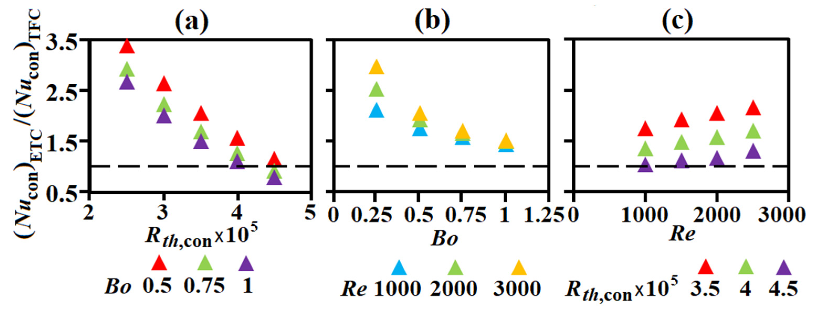
The various varying manners of Nucon against Rth,con, Bo, and Re as well as the differential Nucon levels between the loops with ETC and TFC resulted in the particular patterns of data trends in Figure 7a–c. While most of the Nucon ratios between the loops with ETC and TFC are above than one in Figure 7a–c, the decreased Nucon with Rth,con and the lesser ascending rate of Bo-driven Nucon increase for the loop with ETC resulted in the declined data trends in Figure 7a,b. Above all, the particular ETC configuration produced the higher Nucon than the TFC counterparts at most of the present test conditions with the ratios of (Nucon)ETC/(Nucon)TFC up to 3.39.
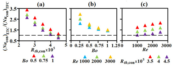
Figure 7.
The ratio of Nucon between the loops with ETC and TFC against (a) Re, (b) Bo, (c) Rth,con.
3.2.3. Overall Thermal Resistance
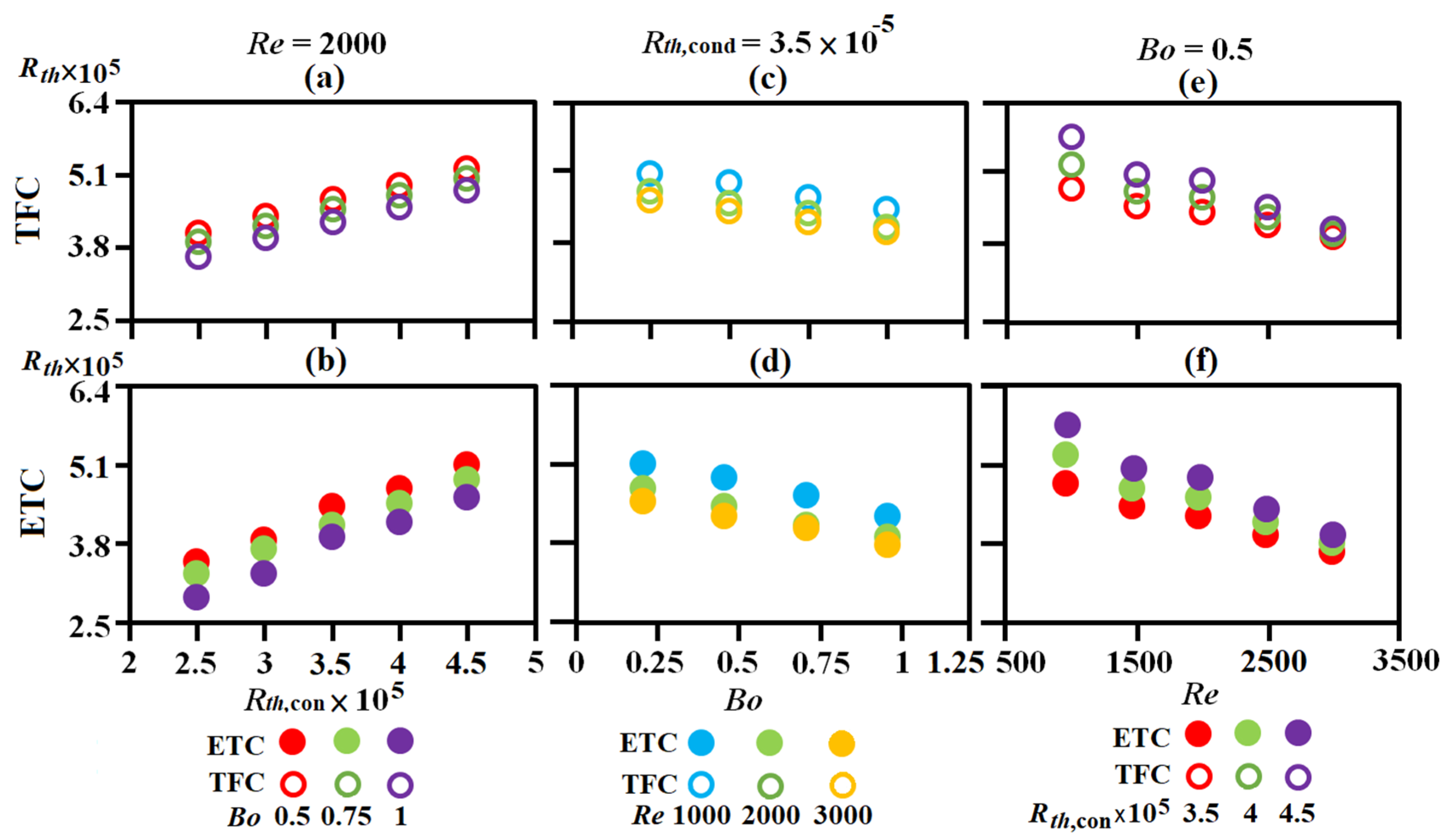
Following the manner constructing Figure 4, Figure 5, Figure 6 and Figure 7, the depictions of Rth variations against Rth,con, Bo, and Re in Figure 8a–f reveal the isolated Rth,con, Bo, and Re impacts on Rth for the loops with TFC and ETC. The effect caused by replacing TFC to ETC on the overall thermal resistance (Rth) featured the combined effects quantified by the ETC-to-TFC Nueva and Nucon ratios at the component level and the reduced Peva and Teva,sat at the system level. Figure 9a–c show the isolated effect of Rth,con, Bo, or Re on the ETC-to-TFC Rth ratio. As Rth is a reciprocal of the overall heat transfer index, the thermal performance improvement by replacing TFC to ETC at system level is affirmed when the ETC-to-TFC Rth ratio becomes less than unity with a lesser ratio for a higher degree of improvement. For both loops, the increase of cooling airflow rate to reduce Rth,con incurs the attendant Rth reduction in Figure 8a,b. As Nueva and Nucon for both loops are increased along with Bo, the Rth data in Figure 8c,d are consistently reduced by increasing Bo. While Nucon for the loop with TFC is decreased along with Re in Figure 6e, the beneficial Re effect on Nueva outweighs the Re-driven Nucon reduction to result in the decreasing trends of Rth in Figure 8e. For the lop with ETC, both Nueva and Nucon are elevated by increasing Re, leading to the Re-driven Rth reduction in Figure 9a. Referring to the ETC-to-TFC Rth ratios in Figure 9a–c, the increase of Bo, Re, or the cooling airflow rate for reducing Rth,con has led to the further reduction of ETC-to-TFC Rth ratio. Thus, the improvements of overall thermal performance caused by replacing TFC to ETC are amplified when Bo, Re, and/or the cooling airflow rate are increased. The ETC-to-TFC Rth ratios are found in the range of 0.81–0.99 at the present test conditions.
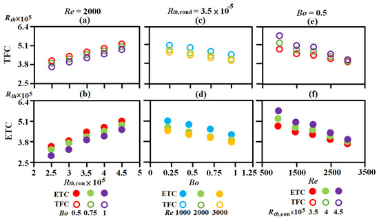
Figure 8.
Variations of Rth along with (a,b) Rth,con at Re = 2000 (c,d) Bo at Rth,con = 3.5 × 10⁻⁵. (e,f) Re at Bo = 0.5 between the loops with TFC and ETC.

Figure 9.
The ratio of Rth between the loops with ETC and TFC against (a) Re, (b) Bo, (c) Rth,con.
3.3. Correlation Development
3.3.1. Nusselt Number Correlation
The developments of Nueva, Nucon, and Rth correlations are based on the data trends typified in the plots of Figure 4, Figure 5, Figure 6, Figure 7, Figure 8 and Figure 9. The depictions of Nueva and Nucon variations in Figure 4c,d and Figure 6c,d reveal a consistent linear-like increasing trend for the loops with ETC and TFC. Accordingly, all the Nueva and Nucon are fitted by a general linear function of Equation (13).
The correlative coefficients of aeva, beva, and acon, bcon in Equation (13) for calculating Nueva and Nucon are summarized in Table 2 and Table 3 for the loops with TFC and ETC.

Table 2.
Coefficients of aeva and beva in Nueva correlation.

Table 3.
Coefficients of acon and bcon in Nucon correlation.
To unravel the functional structures of aeva, beva, and acon, bcon, the a, b coefficients were plotted against Rth,con at a fixed Re of 1000, 2000, 3000, or 3500. All the coefficients aeva, beva and acon, bcon were linearly varied along with Rth,con at a Re. The consistent data trends enabled the aeva,con and beva,con coefficients to be fitted by Equations (14) and (15) into the linear functions of Rth,con.
The values of meva,con, neva,con, feva,con, and geva,con at all the Re tested are collected in Table 4 and Table 5 for the loops with TFC and ETC.

Table 4.
Correlative coefficients of meva,con and neva,con in the aeva,con functions.

Table 5.
Correlative coefficients of meva,con and neva,con in the beva,con functions.
The depictions of meva,con, neva,con, feva,con, and geva,con variations along with Re showed a consistent linear fashion. Accordingly, the meva,con, neva,con, feva,con, and geva,con values in Table 4 and Table 5 were expressed as the Re functions to devise the aeva,con and beva,con correlations for the loops with TFC and ETC as Equations (16)–(23). Substitutions of aeva,con and beva,con functions into Equation (13) acquired the correlations of Nueva and Nucon for the loops with TFC and ETC.
3.3.2. Overall Thermal Resistance Correlation
The development of Rth correlation followed the procedures implanted in Equations (13)–(23). Justified by the linearity of Rth variations along with Rth,con in Figure 6a,b, the Rth correlations for the loops with TFC and ETC were formulated as Equation (24).
In Equation (24), the c and d coefficients are functions of Bo and Re for each loop. Table 6 summarizes the c, and d coefficients at each tested Bo and Re for the loops with TFC and ETC.

Table 6.
c, and d coefficients at each Bo and Re tested for the loops with TFC and ETC.
The implicit cTFC,ETC and dTFC,ETC functions in Table 6 were disclosed after plotting the c and d values against Bo at a Re. The general functional structures of c and d coefficients also followed the linear equation as Equations (25) and (26), respectively.
The correlated values of cTFC,ETC and dTFC,ETC in Equations (25) and (26) at the Re of 1000, 2000, 3000, and 3500 are collected in Table 7.

Table 7.
Correlative coefficients of c1,2 TFC,ETC and d1,2 TFC,ETC in the c and d functions.
After correlating the coefficients c1,2 TFC,ETC and d1,2 TFC,ETC into the functions of Re, the Rth correlations for the loops with TFC and TEC were generated as Equations (27) and (28), respectively.
The justification of the Nueva, Nucon, and Rth correlations for the loops with TFC and ETC was confirmed after comparing the correlative results with all the experimental data as shown by Figure 10a–c, respectively. The maximum discrepancies between 90% of the experimental data and the correlation results for Nueva, Nucon, and Rth as indicated in Figure 10 are ±10%, ±15, and ±15%, respectively. A review of the entire data generated at the parametric conditions tested showed the ranges of Nueva, Nucon, and Rth data for the loop with ETC (TFC) were 114–403 (105–280), 44–143 (16–93), and 2.6 × 10⁻⁵–5.4 × 10⁻⁵ (3 × 10⁻⁵–6.52 × 10⁻⁵), respectively, leading the ratios of (Nueva)ETC/(Nueva)TFC, (Nucon)ETC/(Nucon)TFC, and (Rth)ETC/(Rth)TFC to the respective ranges of 1.1–1.35, 0.8–3.4, and 0.81–0.99.

Figure 10.
Comparisons of experimental data and correlative results for (a) Nueva (b) Nucon (c) Rth.
3.4. Performance Evaluation
3.4.1. Pressure Drop Ratio between ETC and TFC Loops
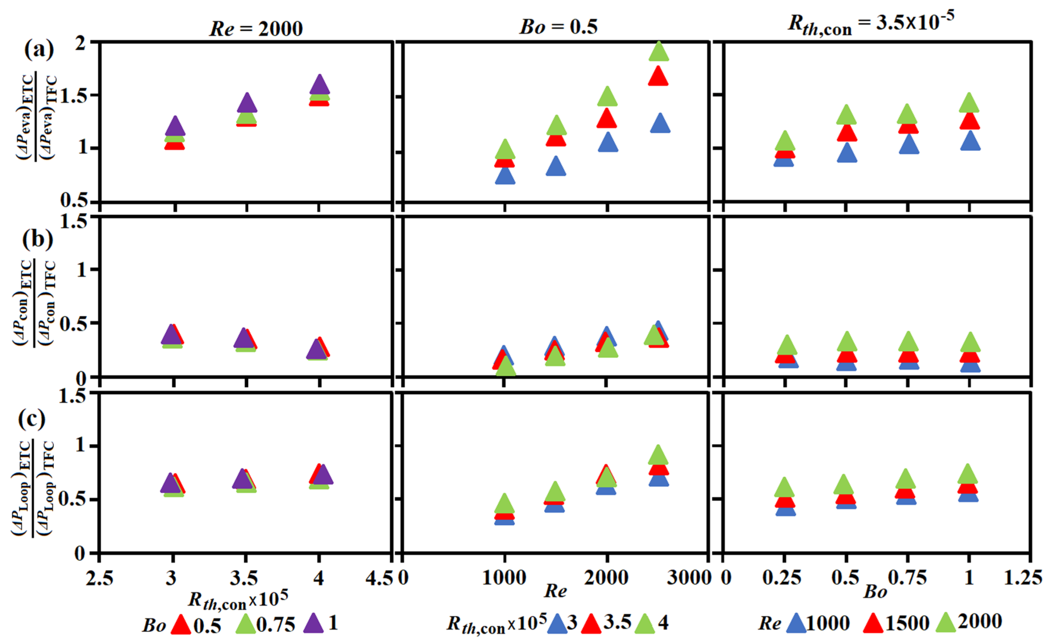
The various hydrothermal factors for the loop with ETC were normalized by the TFC counterparts to quantify the comparative hydrothermal performances between the loops with TFC and ETC at component and system levels. Figure 11 shows the variations of (a) (ΔPeva)ETC/(ΔPeva)TFC (b) (ΔPcon)ETC/(ΔPcon)TFC, and (c) (ΔPLoop)ETC/(ΔPLoop)TFC against Bo, Re, and Rth,con to highlight the comparative pressure drops across evaporator, condenser and loop, respectively. For each loop with TFC or ETC, the values of ΔPeva were increased with Bo, Re, or Rth,con when the other two parameters remained similar. For each thermosyphon loop, the mass flux of refrigerant was increased by raising Re, whereas the increase of Bo at a higher heater power, or the rise of Rth,con by reducing the cooling airflow rate, elevated the dryness factor of the boiling flow through the evaporator. The present ΔPeva variations with Bo, Re, or Rth,con for each loop followed the typical results [45,46,47] in which the pressure drops of boiling flows were increased with mass flux, and, or dryness factor. However, the ascending rate of ΔPeva along with Bo, Re, or Rth,con were different between the loops with TFC and ETC, resulting in the linear-like data variations in the plots of Figure 11. In this regard, the ratios of (ΔPeva)ETC/(ΔPeva)TFC in Figure 11a increased with Rth,con, Re, or Bo; and were mostly raised above than one. In [45,46,47], it was concluded that the two-phase frictional pressure drops for boiling flows were increased with reduced system pressure. At lower evaporator pressures in the loop with ETC, the larger pressure drops of the boiling flow raised the ratios of (ΔPeva)ETC/(ΔPeva)TFC to be above unity in Figure 11a. In the ETC, the pressure drops across the condenser were significantly reduced from that with the intermittent Taylor/Churn vapor bubbles in the saturated regime of TFC. The ratios of (ΔPcon)ETC/(ΔPcon)TFC are considerably less than unity in Figure 11b. The ratios of (ΔPcon)ETC/(ΔPcon)TFC were decreased with Rth,con, or Bo owing to the attendant extension of the saturated regime in each condenser; but were increased by increasing Re that added the frictional drags of liquid films in ETC. The competing effects of Bo, Re, or Rth,con on the ratios of (ΔPeva)ETC/(ΔPeva)TFC and (ΔPcon)ETC/(ΔPcon)TFC as exemplified in Figure 11a,b generated the results of (ΔPloop)ETC/(ΔPloop)TFC in Figure 11c. As the pressure drop across condenser dominated the pressure drop of each loop, the data range of (ΔPloop)ETC/(ΔPloop)TFC in Figure 11c was more similar to the results in Figure 11b rather than that in Figure 11a. At all the present test conditions, the ratios of (ΔPloop)ETC/(ΔPloop)TFC fell in the range of 0.44–0.91 to reflect the larger pumping power consumption for facilitating the refrigerant circulation along the loop with TFC.
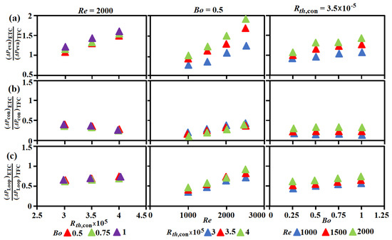
Figure 11.
Variations of (a) (ΔPeva)ETC/(ΔPeva)TFC (b) (ΔPcon)ETC/(ΔPcon)TFC, and (c) (ΔPLoop)ETC/(ΔPLoop)TFC against Bo, Re, and Rth,con.
3.4.2. Merit Indices Evaluated at Constant Pumping Power Consumption for Each Loop
The merit indices MIeva, MIcon, and MIRth defined by Equations (8)–(10) enlighten the comparative hydrothermal performances of evaporator, condenser, and the overall thermal resistance between the loops with ETC and TFC at the criterion of constant pumping power. In this respect, the heat transfer rate (Nueva) per pumping power consumption for facilitating the refrigerant flow through the evaporator (PPeva) is evaluated as Nueva/PPeva. The index of MIeva is the ratio of Nueva/PPeva between the loops with ETC and TFC. A higher evaporator heat transfer rate with ETC is affirmed when MIeva is above than unity; and the higher the MIeva, the more hydrothermal performance improvement for the evaporator is attainable by replacing TFC into ETC. Similarly, the ratio of condenser refrigerant cooling power per pumping power of airflow (CCOP) between the loops with ETC and TFC is defined as MIcon. When MIcon is higher than unity, the condenser performance is improved by replacing TFC into ETC. As a lesser Rth for a thermosyphon loop corresponds to a higher cooling duty at a heat source-to-sink temperature difference, the lower merit index of MIRth stands for the improved loop thermal performance by changing TFC into ETC.
Figure 12a–c depict the variations of MIeva, MIcon, and MIRth with Rth,con, Bo, and Re to highlight the isolated Rth,con, Bo, and Re impacts on these hydrothermal indices. As the ratios of (ΔPeva)ETC/(ΔPeva)TFC, which were generally above than one and increased with Bo, or Rth,con in Figure 11a, the values of MIeva were decreased with Bo, Rth,con in Figure 12a; even if the ratios of (Nueva)ETC/(Nueva)TFC were above than unity and increased with Bo, Re, or Rth,con in Figure 5a–c. However, the increasing rate of (Nueva)ETC/(Nueva)TFC with Re exceeded the corresponding increase of (ΔPeva)ETC/(ΔPeva)TFC. The MIeva index was increased by raising Re. The resultant MIeva values at the present test conditions were between 0.63–1.55. In view of the MIcon performances, the ratios of (ΔPcon)ETC/(ΔPcon)TFC in Figure 11b combined with the heat transfer results in Figure 7a–c to generate the MIcon data trends in Figure 12b. The MIcon variations exhibited the ascending (descending) trends with Bo, Rth,con (Re) in the MIcon range of 1.35–4.76. The combined effects of Bo, Re, and Rth,con on the ratios of (ΔPloop)ETC/(ΔPloop)TFC and (Rth)ETC/(Rth)TFC gave rise the results in Figure 12c with all the MIRth data less than one but increased with Bo, Re, or Rth,con. The present range of MIRth fell between 0.34 and 0.72, indicating the overall thermal performance improvements by replacing TFC into ETC.
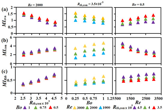
Figure 12.
Variations of (a) MIeva (b) MIcon (c) MIRth with Rth,con, Bo, and Re.
3.4.3. Performance Comparison between ETC and TFC Loops at Constant Cooling Airflow Rate
With the occasions requiring for maximizing the power of heat transmission by a pumped thermosyphon loop at a constant airflow rate through the condenser without considering the pumping power consumptions for facilitated the cooling airflow and the refrigerant flow, the lesser overall thermal resistances (rth) obtained at a similar airflow rate () is preferable. Figure 13 compares the variations of rth against airflow rate () for the loops with TFC and ETC at (a) Re = 2000 (b) Rth,con = 3.5 × 10⁵ (c) Bo = 0.5. For each plot of Figure 13a at constant Re and Bo, and with fixed Rth,con and Re in Figure 13b, the increase of resulted in the respective Rth,con and Bo decreases. Recalling Equation (6) for defining Rth,con, the increase of with Bo and Rth,con at the controlled values required the increase of mass flux of the refrigerant flow, or Re. Thus, Re was increased along with in each plot of Figure 13c. The descending rth in Figure 13a,c, as well as the ascending rth in Figure 13b along with , reflected the isolated Rth,con, Bo, and Re impacts on the overall thermal resistance typified by Figure 6. Nevertheless, with the lower system pressure and hence the lesser saturated temperatures in evaporator for the loop with ETC, the thermal resistance with ETC was consistently lower than the TFC counterpart in all the plots of Figure 13. In this regard, the respective rth ranges for the loops with TFC and ETC were 0.15–0.23 (KW−1) and 0.13–0.21 (KW−1), respectively, at all the airflow rates tested. The adoption of ETC for reducing the condenser pressure drop and altering the vapor-liquid structure from that in TFC has triggered a chain reaction to reduce the system and component pressures, the saturated temperatures and heat transfer rates along the pumped thermosyphon loop to offer the lower MIRth at the constant pumping power condition and the lesser Rth (rth) with the constant cooling airflow rate.
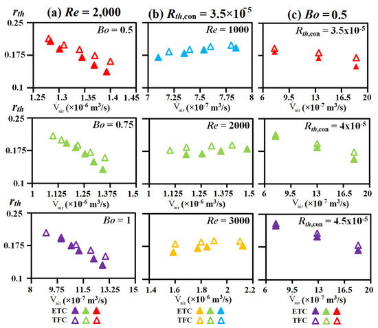
Figure 13.
Variations of rth against for the loops with TFC and ETC at (a) Re = 2000. (b) Rth,con = 3.5 × 10⁻⁵ (c) Bo = 0.5.
3.4.4. Comparative Thermal Resistances of ETC and TFC Loops with Relevant Studies
To disclose the comparative thermal performances of the present pumped thermosyphon loops with TFC and ETC, the variations of rth against Q for the present thermosyphon loops with ETC and TFC are compared with the rth data reported by Setyawan et al. [8], Zhang et al. [30], and Zhang et al. [31]. Owing to the significant pressure drop across the capillary wick in the evaporator, the pump-assisted hybrid heat pipe with wick [8] consumed the largest pumping powers of 0–12 W among the comparative groups in Figure 14. As compared by Setyawan et al. [8] in Figure 14, the pumped-assisted heat pipe using R22 as the working fluid moderately reduced its rth from that without pump. This comparative result agreed with our previous finding [9]. After installing an ejector between the reservoir and condenser in the pump-assisted hybrid heat pipe with the sintered bi-porous nickel wick using ammonia as the working fluid [31], the rth value was noticeably reduced from that reported by Setyawan et al. [8]. Nevertheless, as compared by Figure 14, the added thermal resistance by the wick in the evaporator [8,31] raised the rth values from the present data range and the data detected form the pumped thermosyphon loop without wick [30]. For the pumped thermosyphon loops with the different configurations and working fluids as indicated in Figure 14, all the rth data followed a similar decreasing trend when Q is increased. Owing to the lower pumping powers in the range of 0.015–0.15 W for the present ETC and TFC loops, the present rth values were slightly higher than the results generated at the pumping powers up to 0.3 W as reported by Zhang et al. [31]. Even without considering the pumping power consumed for facilitating the cooling duty at the condenser as compared by Figure 14, the present rth values with ETC were still less than the TFC counterparts.
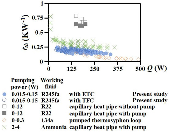
Figure 14.
Comparison of present rth data with the previous measurements reported in [8,30,31].
4. Conclusions
The present experimental investigation highlighted the significance of condenser in affecting the hydrothermal performances of a pumped thermosyphon loop using the typical TFC and ETC as the comparative group with the following salient points concluded.
- The increased operating pressures and saturated temperatures with Bo, Re, or Rth,con triggered the consequent hydrothermal impacts at component and system levels for the pumped thermosyphon loops with TFC and ETC. The higher evaporator pressure in the loop with TFC suppressed the boiling flow heat transfer, raising the ratios of (Nueva)ETC/(Nueva)TFC to the range of 1.1–1.35. However, the two-phase frictional pressure drops of boiling flows increased with reduced pressure. The ratios of (ΔPeva)ETC/(ΔPeva)TFC became above than unity in the range of 0.86–1.9. The competing effect of evaporator pressure on Nueva and ΔPeva has led to the MIeva indices in the range of 0.63–1.55.
- In the TFC, the condensation followed the typical phase transition process from mist annular flow to subcooled flow along the serpentine horizontal tube to considerably raise the pressured drops and reduce the Nucon form the ETC counterparts. The ratios of (Nucon)ETC/(Nucon)TFC and (ΔPcon)ETC/(ΔPcon)TFC were in the respective ranges of 0.8–3.4 and 0.13–0.38 at the present test conditions, leading the MIcon indices to the range of 1.35–4.76.
- Acting by the combined effects attributed to the ETC-to-TFC Nueva and Nucon ratios at component level and the reduced Peva and Teva,sat at system level after replacing TFC by ETC, the ratios of (Rth)ETC/(Rth)TFC in the range of 0.81–0.99 were increased with Bo, Re, or the cooling airflow rate for reducing Rth,con. The overall thermal performance improvements caused by replacing TFC to ETC were amplified by increasing Bo, Re, or, and, the cooling airflow rate. Having accounted the Bo, Re, or Rth,con effects on (ΔPloop)ETC/(ΔPloop)TFC and (Rth)ETC/(Rth)TFC, all the MIRth data in the range of 0.34–0.72 were less than unity but increased with Bo, Re, or Rth,con.
- When the loop performance was compared at a constant airflow rate without considering the pumping power consumption, the values of (rth)ETC in the range of 0.13–0.21 (KW−1) were consistently less than (rth)TFC between 0.15–0.23 (KW−1). The comparative thermal performances between the loops with TFC and ETC at either constant pumping powers or constant cooling airflow rates affirmed the important role of effective and efficient condenser for hydrothermal performance improvements of a pumped thermosyphon loop.S
- Empirical correlations were developed to evaluate the Nueva, Nucon, and Rth values using Bo, Re, and Rth,con as the controlling parameters for the pumped thermosyphon loops with TFC and ETC.
Author Contributions
Conceptualization, S.-W.C.; methodology, S.-W.C.; formal analysis, S.-W.C., Y.-A.T. and C.-L.T.; investigation, S.-W.C., Y.-A.T. and C.-L.T.; resources, S.-W.C.; data curation, Y.-A.T. and C.-L.T.; writing—original draft preparation, S.-W.C.; writing—review and editing, S.-W.C.; supervision, S.-W.C.; project administration, S.-W.C.; funding acquisition, S.-W.C. All authors have read and agreed to the published version of the manuscript.
Funding
This research was funded by Ministry of Science and Technology, Taiwan, grant number MOST 110-2221-E-006-078-MY3.
Acknowledgments
The research facilities were partially supported by Ministry of Science and Technology, Taiwan, under MOST 110-2221-E-006-078-MY3 project.
Conflicts of Interest
The authors declare no conflict of interest.
Nomenclature
| English Symbols | |
| a,b,c,d,m,n | correlative coefficients |
| Bo | boiling number = Q/(hfg) |
| CCOP | condenser coefficient of performance |
| d | entry tube diameter of evaporator (m) |
| h | enthalpy of working fluid (Jkg−1) |
| Δhcon | enthalpy drop of refrigerant across condenser (Jkg−1) |
| hfg | latent heat of working fluid (Jkg−1) |
| kL | thermal conductivity of working fluid (liquid) (Wm−1K−1) |
| MIcon | merit index of condenser |
| MIeva | merit index of evaporator |
| MIeva | merit index of loop thermal performance |
| mass flow rate of working fluid (kgs−1) | |
| Nucon | Nusselt number of condenser = (Q/Acon)d/[(Tcon,sat − Tw,con)kL] |
| Nueva | Nusselt number of evaporator = (Q/Aeva)d/[(Tw,eva − Teva,sat)kL] |
| P | pressure (Nm−2) |
| PPeva | pressure drop of refrigerant flow across evaporator (Nm−2) |
| PPloop | pressure drop of refrigerant flow across entire loop (Nm−2) |
| Pcon | pressure of condenser (Nm−2) |
| ΔPcon | pressure drop across condenser (Nm−2) |
| Peva | pressure of evaporator (Nm−2) |
| ΔPeva | pressure drop across evaporator (Nm−2) |
| Q | heater power (W) |
| Re | Reynolds number at entry of evaporator = 4/πdμ |
| Rth | non-dimensional overall thermal resistance = rthkLd |
| Rth,con | non-dimensional condenser thermal resistance = rth,cond kLd |
| rth | overall thermal resistance = (THF − T∞)/Q (KW−1) |
| rth,con | thermal resistance of condenser = (Tcon,in − T∞)/Q (KW−1) |
| THF | central wall temperature at evaporator (K) |
| Tcon,in | temperature at inlet of condenser (K) |
| Tw,con | wall temperatures of condenser (K) |
| Tw,eva | wall temperatures of evaporator (K) |
| T∞ | cooling airflow entry temperature at condenser inlet (K) |
| volume cooling air flow rate (m3s−1) | |
| x | dryness fraction |
| Greek symbols | |
| μ | viscosity of working fluid (Nms−1) |
| Subscripts | |
| con | condenser |
| eva | evaporator |
| loop | pumped thermosyphon loop |
| sat | saturated state |
| Abbreviations | |
| ETC | expansion tank condenser |
| TFC | tube fin condenser |
References
- Ambrose, J.; Feild, A.; Holmes, H. A pumped heat pipe cold plate for high-flux applications. Exp. Therm. Fluid Sci. 1995, 10, 156–162. [Google Scholar] [CrossRef]
- Zhang, P.; Weia, X.; Yana, L.; Xua, H.; Yang, T. Review of recent developments on pump-assisted two-phase flow cooling technology. Appl. Therm. Eng. 2019, 150, 811–823. [Google Scholar] [CrossRef]
- Crepinsek, M.; Park, C. Effect of operational conditions on cooling performance of pump-assisted and capillary-driven two-phase loop. J. Thermophys. Heat Transf. 2011, 25, 572–580. [Google Scholar] [CrossRef]
- Crepinsek, M.; Park, C. Experimental analysis of pump-assisted and capillary-driven dual-evaporators two-phase cooling loop. Appl. Therm. Eng. 2012, 38, 133–142. [Google Scholar] [CrossRef]
- Zhang, Z.; Sun, X.-H.; Tong, G.-N.; Huang, Z.-C.; He, Z.-H.; Pauw, A.; van Es, J.; Battiston, R.; Borsini, S.; Laudi, E.; et al. Stable and self-adaptive performance of mechanically pumped CO2 two-phase loops for AMS-02 tracker thermal control in vacuum. Appl. Therm. Eng. 2011, 31, 3783–3791. [Google Scholar] [CrossRef]
- Jiang, C.; Liu, W.; Wang, H.; Wang, D.; Yang, J.; Li, J.; Liu, Z. Experimental investigation of pump-assisted capillary phase change loop. Appl. Therm. Eng. 2014, 71, 581–588. [Google Scholar] [CrossRef]
- Jiang, C.; Liu, W.; Liu, Z.; Yang, J.; Duan, B.; Luo, X. Startup characteristics of pump-assisted capillary phase change loop. Appl. Therm. Eng. 2017, 126, 1115–1125. [Google Scholar] [CrossRef]
- Setyawan, I.; Putra, N.; Hakim, I.I. Experimental investigation of the operating characteristics of a hybrid loop heat pipe using pump assistance. Appl. Therm. Eng. 2018, 130, 10–16. [Google Scholar] [CrossRef]
- Chang, S.W.; Chiang, K.-F.; Lin, F.-C.; Hung, W.-S. Thermal performance of pump-assisted loop heat pipe using R245fa as working fluid. In Proceedings of the 19th IEEE Intersociety Conference on Thermal and Thermomechanical Phenomena in Electronic Systems (ITherm 2020), San Diego, CA, USA, 21 July–19 August 2020; p. 136. [Google Scholar]
- Parida, P.R.; Schultz, M.D.; Chainer, T. Sim2Cool: A two-phase cooling system simulator and design tool. In Proceedings of the 17th IEEE Intersociety Conference on Thermal and Thermomechanical Phenomena in Electronic Systems (ITherm 2018), San Diego, CA, USA, 29 May–1 June 2018; pp. 271–280. [Google Scholar]
- Zhang, S.; Ma, G.; Zhou, F. Experimental Study on a Pump Driven Loop-Heat Pipe for Data Center Cooling. J. Energy Eng. 2015, 141, 04014054. [Google Scholar] [CrossRef]
- Zhou, F.; Wei, C.; Ma, G. Development and analysis of a pump-driven loop heat pipe unit for cooling a small data center. Appl. Therm. Eng. 2017, 124, 1169–1175. [Google Scholar] [CrossRef]
- Zhou, F.; Duan, W.; Ma, G. Thermal performance of a multi-loop pump-driven heat pipe as an energy recovery ventilator for buildings. Appl. Therm. Eng. 2018, 138, 648–656. [Google Scholar] [CrossRef]
- Karayiannis, T.; Mahmoud, M. Flow boiling in microchannels: Fundamentals and applications. Appl. Therm. Eng. 2017, 115, 1372–1397. [Google Scholar] [CrossRef]
- Alam, T.; Lee, P.S.; Yap, C.R.; Jin, L. Experimental investigation of local flow boiling heat transfer and pressure drop char-acteristics in microgap channel. Int. J. Multiph. Flow 2012, 42, 164–174. [Google Scholar] [CrossRef]
- Wang, H.-L.; Wu, H.-C.; Wang, S.K.; Hung, T.-C.; Yang, R.-J. A study of mini-channel thermal module design for achieving high stability and high capability in electronic cooling. Appl. Therm. Eng. 2013, 51, 1144–1153. [Google Scholar] [CrossRef]
- Prajapati, Y.K.; Pathak, M.; Khan, M.K. A comparative study of flow boiling heat transfer in three different configurations of microchannels. Int. J. Heat Mass Transf. 2015, 85, 711–722. [Google Scholar] [CrossRef]
- Kalani, A.; Kandlikar, S.G. Flow patterns and heat transfer mechanisms during flow boiling over open microchannels in tapered manifold (OMM). Int. J. Heat Mass Transf. 2015, 89, 494–504. [Google Scholar] [CrossRef]
- Tamanna, A.; Lee, P.S. Flow boiling heat transfer and pressure drop characteristics in expanding silicon microgap heat sink. Int. J. Heat Mass Transf. 2015, 82, 1–15. [Google Scholar] [CrossRef]
- Zhang, S.; Tang, Y.; Yuan, W.; Zeng, J.; Xie, Y. A comparative study of flow boiling performance in the interconnected mi-crochannel net and rectangular microchannels. Int. J. Heat Mass Transf. 2015, 85, 711–722. [Google Scholar]
- Zhang, S.; Sun, Y.; Yuan, W.; Tang, Y.; Tang, H.; Tang, K. Effects of heat flux, mass flux and channel width on flow boiling performance of porous interconnected microchannel nets. Exp. Therm. Fluid Sci. 2018, 90, 310–318. [Google Scholar] [CrossRef]
- Deng, D.; Wan, W.; Qin, Y.; Zhang, J.; Chu, X. Flow boiling enhancement of structured microchannels with micro pin fins. Int. J. Heat Mass Transf. 2017, 105, 338–349. [Google Scholar] [CrossRef]
- Sharma, D.; Ghosh, D.P.; Saha, S.K.; Raj, R. Thermohydraulic characterization of flow boiling in a nanostructured micro-channel heat sink with vapor venting manifold. Appl. Therm. Eng. 2019, 130, 1249–1259. [Google Scholar]
- Wang, Y.; Peles, Y. Subcooled flow boiling in a microchannel with a pin fin and a liquid jet in crossflow. Int. J. Heat Mass Transf. 2015, 86, 165–173. [Google Scholar] [CrossRef]
- Deng, D.; Wan, W.; Shao, H.; Tang, Y.; Feng, J.; Zeng, J. Effects of operation parameters on flow boiling characteristics of heat sink cooling systems with reentrant porous microchannels. Energy Convers. Manag. 2015, 96, 340–351. [Google Scholar] [CrossRef]
- Huang, H.; Borhani, N.; Thome, J.R. Experimental investigation on flow boiling pressure drop and heat transfer of R1233zd(E) in a multi-microchannel evaporator. Int. J. Heat Mass Transf. 2016, 98, 596–610. [Google Scholar] [CrossRef]
- Radwan, A.; Ookawara, S.; Mori, S.; Ahmed, M. Uniform cooling for concentrator photovoltaic cells and electronic chips by forced convective boiling in 3D-printed monolithic double-layer microchannel heat sink. Energy Convers. Manag. 2018, 166, 356–371. [Google Scholar] [CrossRef]
- Guo, Z.; Shao, J.; Li, X.; Liu, R.; Wang, W.; Tian, X. Application of pump-assisted separate heat pipe on dehumidifying enhancement in air conditioning system. Appl. Therm. Eng. 2016, 98, 374–379. [Google Scholar] [CrossRef]
- Zhou, F.; Duan, W.; Ma, G. Thermal performance of a pump-driven loop heat pipe as an air-to-air energy recovery device. Energy Build. 2017, 151, 206–216. [Google Scholar] [CrossRef]
- Zhang, P.; Li, X.; Shi, W.; Wang, B.; Rong, X. Experimentally comparative study on two-phase natural and pump-driven loop used in HVAC systems. Appl. Therm. Eng. 2018, 142, 321–333. [Google Scholar] [CrossRef]
- Zhang, H.; Jiang, C.; Zhang, Z.; Liu, Z.; Luo, X.; Liu, W. A study on thermal performance of a pump-assisted loop heat pipe with ammonia as working fluid. Appl. Therm. Eng. 2020, 175, 115342. [Google Scholar] [CrossRef]
- Vasta, S.; Palomba, V.; La Rosa, D.; Bonanno, A. Experimental assessment and numerical study of a pump-assisted loop heat pipe for high capacity thermal systems. Appl. Therm. Eng. 2020, 180, 115828. [Google Scholar] [CrossRef]
- Meng, Q.; Zhao, Z.; Zhang, T.; Es, J.; Pauw, A.; Zhang, H.; Yan, Y. Experimental study on the transient behaviors of me-chanically pumped two-phase loop with a novel accumulator for thermal control of space camera payload. Appl. Therm. Eng. 2021, 179, 115714. [Google Scholar] [CrossRef]
- Tariq, A.; Prajapati, A.N. Heat Transfer Characteristics Within the Matrix Cooling Channels. J. Turbomach. 2021, 143, 051007. [Google Scholar] [CrossRef]
- Kline, S.J.; McClintock, F.A. Describing uncertainties in single sample experiments. Mech. Eng. 1953, 75, 3–8. [Google Scholar]
- Hsieh, Y.; Lin, T. Saturated flow boiling heat transfer and pressure drop of refrigerant R-410A in a vertical plate heat exchanger. Int. J. Heat Mass Transf. 2002, 45, 1033–1044. [Google Scholar] [CrossRef]
- Park, C.Y.; Hrnjak, P. CO2 flow condensation heat transfer and pressure drop in multi-port microchannels at low temper-atures. Int. J. 2009, 32, 1129–1139. [Google Scholar]
- Kim, N.-H. Condensation heat transfer and pressure drop of R-410A in flat aluminum multi-port tubes. Heat Mass Transf. 2017, 54, 523–535. [Google Scholar] [CrossRef]
- Bang, K.; Kim, K.; Lee, S.; Lee, B. Pressure effect on flow boiling heat transfer of water in minichannels. Int. J. Therm. Sci. 2011, 50, 280–286. [Google Scholar] [CrossRef]
- Rossato, M.; Del Col, D.; Muzzolon, A.; Rossetto, L. Flow boiling of R32 inside a brazed plate heat exchanger. Int. J. Refrig. 2016, 69, 165–174. [Google Scholar] [CrossRef]
- Yan, Y.-Y.; Lin, T.-F. Evaporation Heat Transfer and Pressure Drop of Refrigerant R-134a in a Plate Heat Exchanger. J. Heat Transf. 1999, 121, 118–127. [Google Scholar] [CrossRef]
- Zhang, D.-C.; Ji, W.-T.; Tao, W.-Q. Condensation heat transfer of HFC134a on horizontal low thermal conductivity tubes. Int. Commun. Heat Mass Transf. 2007, 34, 917–923. [Google Scholar] [CrossRef]
- Wang, B.-X.; Du, X.-Z. Condensation on the outside surface of a small/mini diameter tube for vapor flowing through a horizontal annulus surround by an adiabatic concentric tube. Int. J. Heat Mass Transf. 2000, 43, 1391–1398. [Google Scholar] [CrossRef]
- El Hajal, J.; Thome, J.; Cavallini, A. Condensation in horizontal tubes, part 1: Two-phase flow pattern map. Int. J. Heat Mass Transf. 2003, 46, 3349–3363. [Google Scholar] [CrossRef]
- Wu, J.; Koettig, T.; Franke, C.; Helmer, D.; Eisel, T.; Haug, F.; Bremer, J. Investigation of heat transfer and pressure drop of CO2 two-phase flow in a horizontal mini-channel. Int. J. Heat Mass Transf. 2011, 54, 2154–2162. [Google Scholar] [CrossRef]
- Tibiriçá, C.B.; Ribatski, G. Two-Phase Frictional Pressure Drop and Flow Boiling Heat Transfer for R245fa in a 2.32-mm Tube. Heat Transf. Eng. 2011, 32, 1139–1149. [Google Scholar] [CrossRef]
- Tibirica, C.B.; Da-Silva, J.D.; Ribatski, G. Experimental investigation of flow boiling pressure drop of R134a in a microscale horizontal smooth tube. ASME J. Therm. Sci. Eng. Appl. 2011, 3, 011006. [Google Scholar] [CrossRef]
Publisher’s Note: MDPI stays neutral with regard to jurisdictional claims in published maps and institutional affiliations. |
© 2022 by the authors. Licensee MDPI, Basel, Switzerland. This article is an open access article distributed under the terms and conditions of the Creative Commons Attribution (CC BY) license (https://creativecommons.org/licenses/by/4.0/).

