Review

Review of Recent Offshore Photovoltaics Development

1
Key Laboratory of Solar Energy Science and Technology in Jiangsu Province, Southeast University, No. 2 Si Pai Lou, Nanjing 210096, China
2
Energy Storage Research Center, Southeast University, No. 2 Si Pai Lou, Nanjing 210096, China
3
School of Science, Aalto University, P.O. Box 15100, Aalto, FI-00076 Espoo, Finland
*
Authors to whom correspondence should be addressed.
Energies 2022, 15(20), 7462; https://doi.org/10.3390/en15207462
Submission received: 6 September 2022 / Revised: 19 September 2022 / Accepted: 21 September 2022 / Published: 11 October 2022
(This article belongs to the Special Issue Advances in Solar Photovoltaic Power Generation)

Abstract

:
Photovoltaic power generation (PV) has significantly grown in recent years and it is perceived as one of the key strategies to reach carbon neutrality. Due to a low power density, PV requires much space, which may limit PV expansion in the future. Placing PV on water has therefore become an interesting alternative siting solution in several countries. China has the largest fleet of water floating photovoltaic power stations. Water-based PV is typically installed on inland shores, but now offshore areas may become the next step of development. In this paper, the background of offshore photovoltaic power generation and an analysis of existing offshore photovoltaic systems is presented. Fixed pile-based photovoltaic systems are stationary PV systems in offshore or tidal areas characterized by higher safety, but also a higher initial investment. Wave-proof PV systems are highly modular, easier to install, and more practical in countries with high population density and less available land. Floating platform photovoltaic systems are built on a floating platform with a floating body and frame structure. The photovoltaic module is installed on the floating platform at a certain height, which can avoid the direct action of waves. Floating thin-film PV is one of the most recently developed water-based PV systems. It has a reinforced film that can fluctuate with the waves, adapting to the wave and wind load. This paper finally discusses the challenges encountered by offshore PV and presents future prospects.

1. Introduction

The public awareness of the energy and climate crisis has accelerated the development of renewable energy sources, solar energy being one of the most promising alternatives available. The most common form of solar energy is photovoltaics (PV) transforming sunlight directly into electricity [1]. Due to its low-cost, ease of installation, and cleanliness, PV as a renewable energy will flourish and drive the transformation of the energy industry [2].
The solar photovoltaic sector has grown rapidly during the past decade, resulting in a decreasing amount of land available for expansion. It is expected that by the mid-2020s, the development of solar photovoltaic and wind technologies will lead to a renewable energy market that will surpass that of fossil energy, meeting more than half of global electricity demand by 2040 [3]. For example, the cumulative capacity of the PV industry in the United States increased from 218 MW in 2005 to around 51,000 MW in 2017 [4]. Offshore renewables are also identified as key areas in the EU’s transition to reach carbon neutrality by 2050, including the installation of 40 GW of ocean energy such as offshore solar [5]. Additionally, about 50% of the world’s total population resides within 100 km from the shore, increasing the need for supplying energy to these areas [6]. Accordingly, there is a clear demand for developing floating water-based photovoltaic power plants.
SPG Solar installed the very first commercial floating PV (FPV) system in a reservoir in California [7,8] in 2007. A 20 kW FPV plant was erected in Aichi Prefecture in Japan by the National Institute of Advanced Industrial Science and Technology in 2007 [9]. Shortly thereafter, the FPV system rapidly spread elsewhere, notably to China, Singapore, South Korea, Norway, France, and Spain. In 2021, a 3 MW offshore PV system coupled with a fixed wind farm was installed in Belgium [10]. Having developed the technology very quickly, China has emerged as the world’s largest market building floating solar power plants, with tens or even hundreds of megawatts of capacity despite starting later than many other nations [9]. Currently, floating photovoltaic projects on water are mainly located in inland waters with limited wave movements such as ponds, small and medium-sized natural lakes, and hydroelectric dams. A typical FPV facility has four components: the float, the PV modules and their supporting system, the electrical equipment, and mooring and anchoring [11].
There is an increasing interest from industries to expand FPV to marine habitats such as oceans, where FPV has less influence on the marine environment and does not use up water or land resources. The placement of an FPV system over bodies of water has several benefits, including being easier in combination with other industries, higher capacity, and the reduction of dust accumulation [9]. Indeed, FPV also eliminates the need for major site preparation (e.g., no laying of foundations) and can be easier to install in sites with low anchoring and mooring requirements [11]. Therefore, it is imperative to investigate the technological viability and difficulties of developing FPV in maritime situations.
The current market has been influenced by several large PV plants in recent years, most of which have emerged in China. SERIS in [12] shows a breakdown of the FPV installed power worldwide, by country and peak power. China has a total share of 73% (950 MWp), followed by Japan with a total share of 16% (180 MWp), Korea with 6%, and other countries with a share of the remaining 5%.
In this review, we briefly assess the characteristics of four major FPV system concepts and their potential for offshore applications through previous case studies. The FPV systems include a fixed pile-based photovoltaic system, floating PV, floating platform PV, and floating thin-film PV. The approach of this review is as follows: An overview of offshore FPV is briefly discussed in the first section; the second section demonstrates the benefits and drawbacks of four common FPV system applications; and the challenges of offshore FPV are presented in the third section.

2. Floating PV Systems

2.1. Fixed Pile-Based Photovoltaic Systems

Fixed pile-based PV systems have been used in water areas such as reservoirs and fish ponds. The Solar Energy Center at Southeast University in China has pioneered several large-scale over-water fixed pile-based photovoltaic systems in China and abroad. For example, a fixed pile-based photovoltaic system in a reservoir was adopted in the Vietnam Oil Tinh photovoltaic project in cooperation with PowerChina Huadong Engineering Corporation (PHEC). The total installed capacity of the project eventually reached 500 MWp. Another project built in cooperation with the Southeast University and PHEC included a fishery-photovoltaic project in Tianchang City, Anhui Province. In the first year of operation, the project generated 490 GWh of electricity.
By analogy with over-water PV systems, the construction of offshore fixed-pile PV systems benefits from more open sea area without shading, which can increase PV power generation. However, the associated risks may also be higher. The technical challenges of the offshore piled photovoltaics are mainly linked to the following four considerations:
(1)
The need for better anti-corrosion protection, especially for electrical equipment (C5 rating);
(2)
The need to build wave protection facilities (permeable, slope, and floating dikes);
(3)
The need to consider the impact of sea ice;
(4)
The need for a detailed demonstration of the impact of storm surges.
All the above-mentioned demands on the installation and fixing of the pile foundations put high requirements on the system solutions. When installing the piles, e.g., the “Beidou Cloud” positioning technology and water level control elevation method can be used to improve the accuracy of controlling the design parameters such as pile center position, pile top, and verticality. At the same time, the construction work can be eased by an on-surface propeller and using a clamp to hold the finished pile, while applying horizontal force to the pile. The piling equipment can move quickly and accurately from pile to pile along a guide rail, which shortens the time of positioning the pipe pile and moving the piling vessel, and significantly improves the efficiency of the pile-sinking construction on water. In addition, a new type of PV module installation platform on water has been developed. The platform is equipped with three legs with a hydraulic system, which can realize the movement in all directions and precisely control the movement distance, which reduces the inevitable interruption time during the installation of PV modules on water and improves the efficiency of PV module installation construction.
Hu Jianke and Jun Wang et al. [13] proposed a fixed tracking photovoltaic system that can be used offshore. The wind and wave load on the system was modeled with SAP2000, and it was found that a disc of 40 m diameter was within accepted values. The advantage of the system is that there is a retractable column, which allows the whole system to adjust with the floating of the water to ensure that the whole system is stressed in a balanced way. Another advantage of the system is that the entire disk can be rotated to track the sun, which increases the power generation. However, this system is only suitable for offshore areas, where the sea level does not vary much. Moreover, it lacks protection measures against extreme weather.
In June 2021, a mudflat PV system was connected to the grid in Xiangshan, Zhejiang Province of China. The project is the largest coastal mudflat fishery photovoltaic project in China. More than 3 square kilometers of mudflats are covered with 300 MWp of silicon solar cells. It is expected to deliver 340 GWh annually and to reduce the CO2 emissions by 0.27 million tons. The photovoltaic modules on the support frame produce electricity, and the sea below being shaded by the PV panels allows species-specific aquaculture.
A new round of piled photovoltaic system construction projects was launched in Shandong, China in 2022. The project includes ten offshore photovoltaic sites, located in six cities. According to the documents released by the Institute of Water Resources and Hydropower Planning and Design [14], the total installed capacity of the project will be 11.25 GWp. The largest single site has an installed capacity of 2.7 GWp, and the smallest one 0.4 GWp, respectively. The sea depth is less than 8 m to guarantee maximum safety for the PV units.
A 550 MWp fish-light complementary project was built by China New Energy, located in an industrial cluster area in southern Zhejiang Province of Wenzhou, in 2021 [15]. It used pile-based fixed PV covering an area of about 5 square kilometers, and is expected to generate 650 GWh of electricity annually. This project makes use of innovative large scale and complex construction on the surface, but also skillfully combines aquaculture and photovoltaic power generation to increase the economic value per unit area of sea area and to reduce resource consumption.
According to the Enel Innovation Lab in Catania (Italy), the obtained results show that passive water cooling in the offshore PV increases the energy collected by 3% and 2.6% for the bifacial and monofacial technology, respectively, compared with proof PV. Active water cooling in offshore PV increases the collected energy by 9.7% and 9.5% for the bifacial and monofacial, respectively [16].
As an early form of offshore photovoltaic, pile-based offshore PV is generally only used in offshore or mudflat areas, and therefore its geographical applicability is inferior to floating PV. However, because it employs fixed columns deep into the seabed, it has better wind and wave protection than floating photovoltaic systems, making the whole system safer. At the same time, it can be complemented with fishery activities, increasing the economic benefits.

2.2. Wave-Proof Floating Photovoltaic

The basic components of offshore floating PV are roughly the same as with piled fixed PV. Compared to piled PV, which is much more expensive and difficult to build in deeper waters, floating PV offers better opportunities, especially in regions with a high population density and limited available land. In addition, floating PV can also reduce water evaporation because of the shading effect of PV panels. Floating PV is also highly modular, making installation easier and faster. Therefore, floating PV is more adaptable to offshore environments than the pile-fixed PV. The main components of a generic floating PV [17] are shown in Figure 1: (a) floats for providing buoyancy to the modules on water; (b) PV modules and their support systems to support the weight of the modules and transmit the pressure of floating; (c) electrical equipment, such as inverters, to convert the PV DC power to AC power; and (d) mooring and anchoring, which are used to secure the module installation to the sea bed. When applied to specific conditions, the above components may need to be modified, e.g., using rectangular floats made of high-density polyethylene [18], or using steel tubes with fixed angle PV modules supporting galvanized steel frames [18], or even using more novel solutions such as membranes [19].
Currently, the most commonly used floating structure is a single HDPE floating point [20]. Compared to the traditional stationary floating photovoltaic systems on rivers and lakes, which do not consider waves, this small independent float connected by connecting pins is usually only suitable for wave heights of 1 m [21]. In order to find the best geometry for the floating bodies and to solve the problem of how they are connected to each other [22], Grech et al. [23] built and tested four different prototype offshore floating PV installations, observing that the power output of the PV panels increases due to the cooler environment.
Construction of breakwaters or other wave attenuation facilities is important to protect offshore PV waters. Floating breakwaters float around the PV platform to protect the PV modules. Various shapes of floating breakwaters can block more than 50% of the waves at a period of 6 s [24]. The pile-permeable breakwater (Figure 2), on the other hand, uses the permeable design [25] to reduce the waves by changing the wave energy when the waves come in. In this structure, the direction of water movement will change and there will be a stronger collision effect, also forming vortices, which can effectively consume the wave energy after several layers.
Another simple structure and widely used floating body application mode is the single floating box type, though its wave protection effect is often unsatisfactory. In order to further improve the breakwater performance, domestic and foreign academics have improved the structure from the perspective of increasing wave reflection and wave energy loss, mainly with multi-floating box type and floating box-plate type breakwaters [26]. The advantages of multi-floating box breakwaters are their simple structure and easy manufacturing and construction; the disadvantages are their higher manufacturing cost compared with single-floating box breakwaters. Floating box-plate breakwaters mainly include vertical and horizontal plates, among which vertical plates have poor wave protection under short-period waves, while horizontal plates have problems such as low structural safety [26]. Shen Yusheng et al. [27] compared the wave protection effect of a double-row floating box with that of a single floating box type, finding that the wave protection effect of the former was significantly better than that of the latter; they also conducted a comparison of the wave protection effect when a double-row floating box was connected in different ways, and the results showed that the wave protection effect was the best when it was rigidly connected. Liu Weijie et al. [28] invented a circular floating breakwater, including multiple circular arc-shaped floating breakwater units with the same radius of curvature connected, which does not need to consider the main wave direction, wave bypassing, etc., and forms a smooth circular area of water at sea; in addition, the distance between the inner and outer circles can be set independently according to the wavelength.

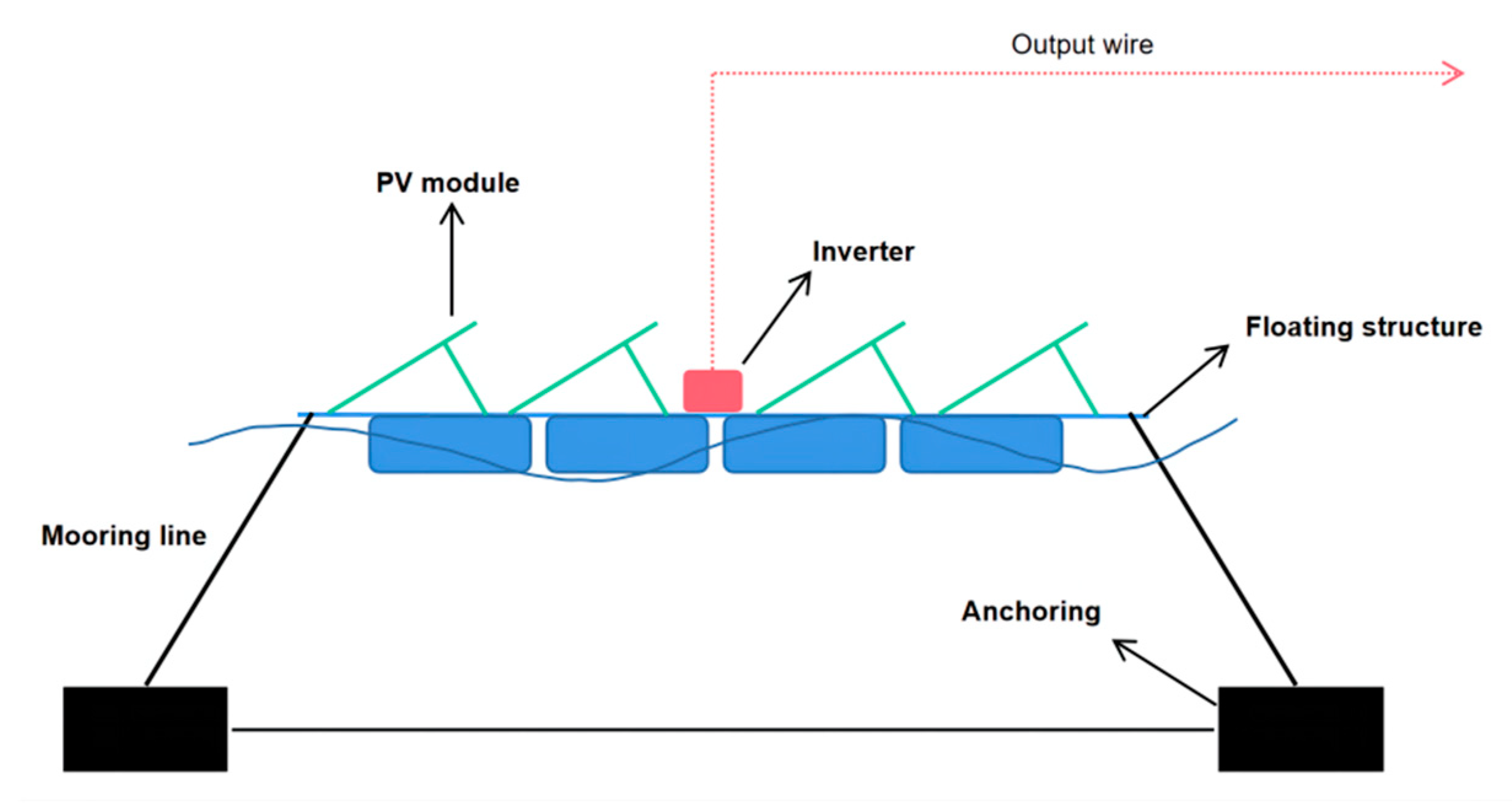
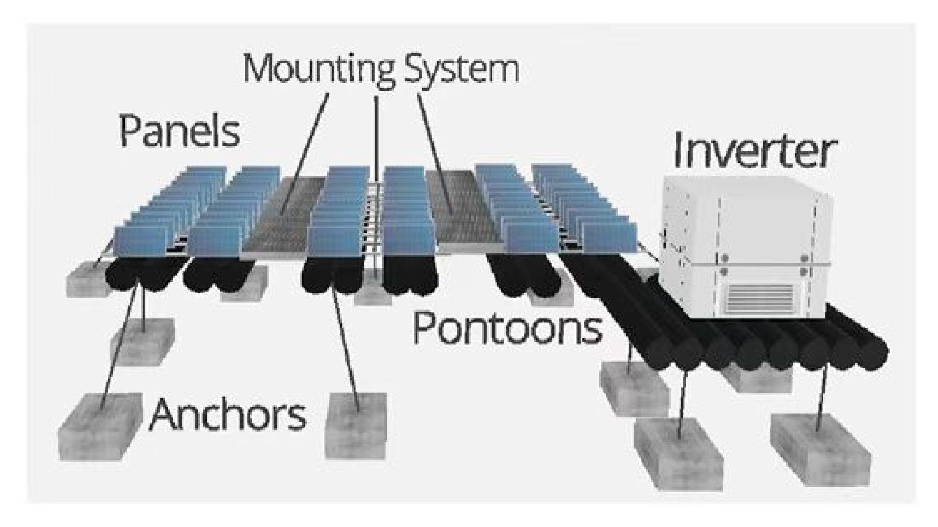
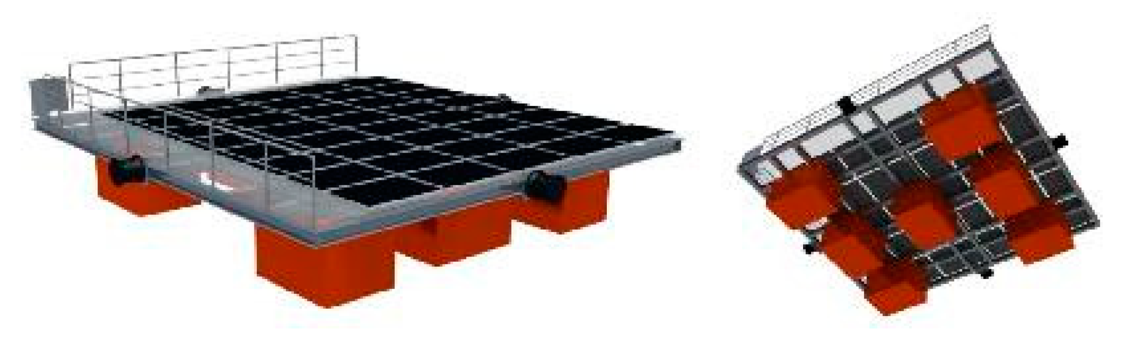
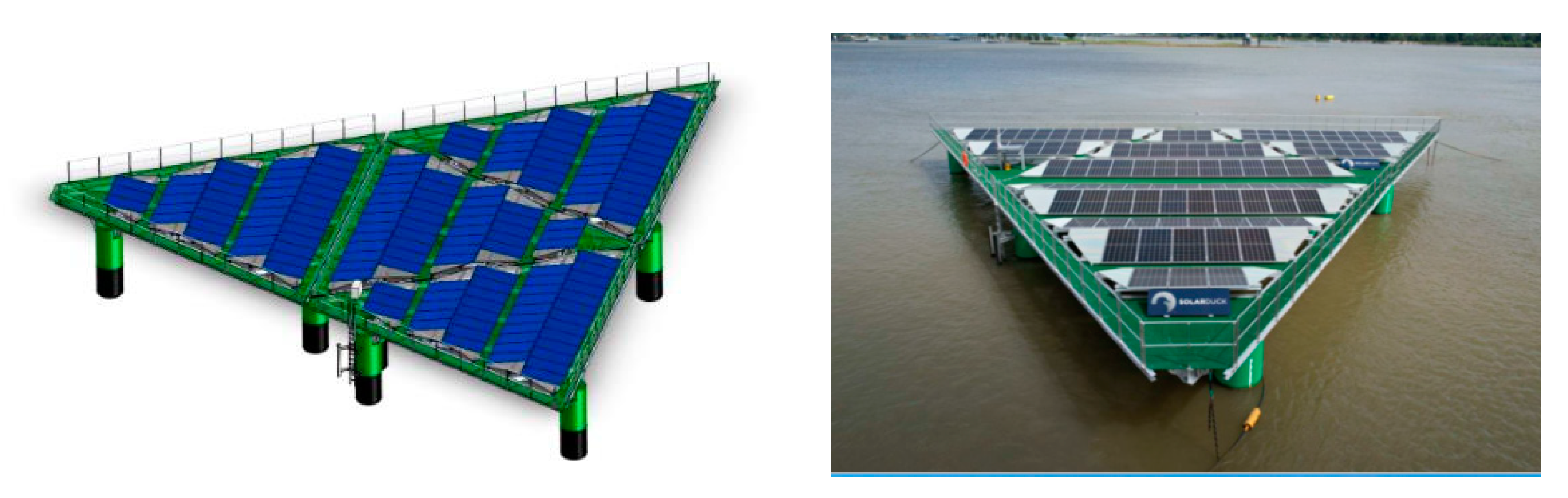
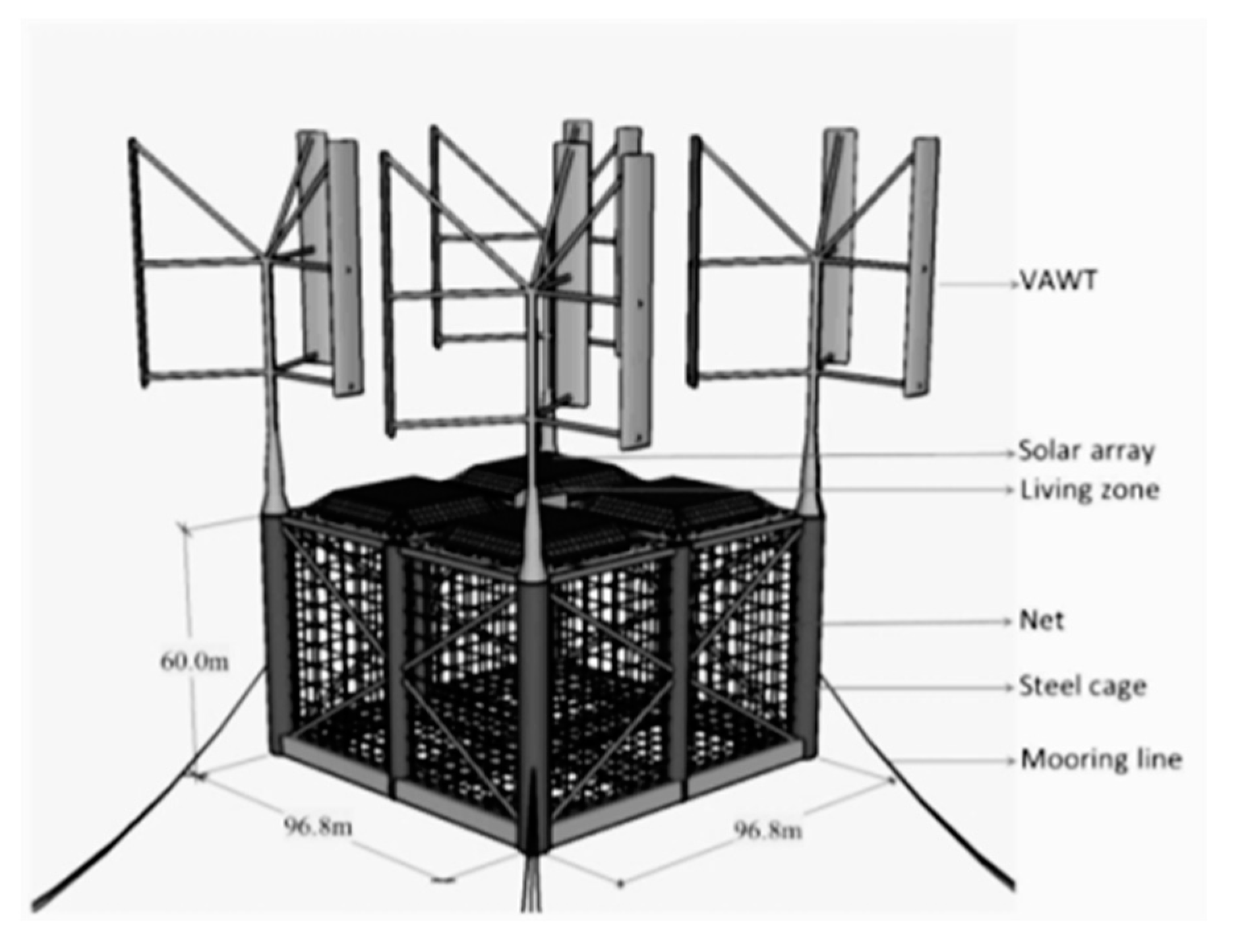
2.3. Floating Platform Photovoltaic Systems

In a floating platform scheme, the water flow through the floating body and frame structure and the photovoltaic components are installed at a certain height in the floating platform to avoid the direct effect of the waves. This is already a quite mature scheme for commercial use.
A floating platform PV system (Figure 3) was designed by Sáde et al. based on various concepts shown in the FPV modeling book by Rosa-Clot et al. [29] and the World Bank Group report [18]. Photovoltaic modules, one of the primary parts, are typically constructed from non-toxic silicon, mounted on an aluminum frame, and have a service life of up to 25 to 30 years. Solar panels are fixed in place by mounting structures made of galvanized steel or aluminum [30] and form the best angle to absorb energy. The structures are attached to pontoons made of high-density polyethylene (HDPE) to float on water. The buoy support modules and cables, and the additional float tube is used to support the inverter. The overflow pipe is formed by rotation or blow molding [11]. The function of the inverter is to convert the DC generated by the module [30] into AC. Their lifespan is about 10 years [31]. The inverter will be connected to the buoyant structure to reduce any power loss through transmission [18].
The Australian Swimsol company has developed a floating offshore photovoltaic system called Solar Sea (Figure 4). The system consists of a floating platform (14 m by 14 m) consisting of pontoons and an upper truss structure, heavy duty solar panels developed specifically for tropical marine environments (durable and efficient, twice as durable as standard panels), and the corresponding electrical systems [18]. The floating PV system has been tested in offshore waters of the Maldives, proving that it can be used in ocean currents, tides, extreme ultraviolet light, humidity, and corrosive environments, but the limited wave resistance is only 1.5 m, which limits its nearshore application. Because of its small size, truss-like floating structure, and floating distribution, the system has a larger surface area and can protect the solar panels from waves. Several versions of this system type have been adapted to different wave conditions, and the system can generate electricity at a cost as low as $0.12 kWh−1 with a lifetime of about 30 years [18].
The Norwegian Moss Maritime system employs a floating photovoltaic system called the Floating Solar Park (Figure 5). The system is based on standardized modules designed for specific locations and weather. A typical square module is about 10 × 10 m in size, but it can vary depending on the design considerations. The floating platform of the PV system module consists of a number of pontoons at the bottom and a platform structure at the top, on which the solar panels can be placed. The platform is supported by a number of cubic floats to provide the required buoyancy and air gaps. Flexible connections at the center of these modules enable the modules to move along the wave slope, which in combination with the rigid structure of the modules enables the system to withstand waves of up to three to four meters for long periods of time. Due to its modular and simple design, the system can be used both inland and offshore and is ideally suited for large-scale applications. The system will be tested in the Norwegian island of Froya. No specific wave and wind parameters have been provided for this system, although the test will be conducted in rough sea conditions. From the design specification and test site indicated, it is more inclined to nearshore applications [33].
The Australian company’s HelioFloat concept is based on a floating lightweight platform manufacturing technology (Figure 6). The basic idea is to levitate the platform on a cushion of air. The platform relies on a series of pontoons made of soft, flexible materials to provide buoyancy. At the top of the pontoons, air that cannot escape keeps the cylinders afloat, while at the bottom, the air comes into direct contact with the water. Instead of a sealed air cushion, a column of air above the water acts as a shock absorber. When waves hit the sides of the pontoons, they bend, so they are under less pressure than conventional pontoons, allowing the PV system to withstand large waves while remaining stable. For safety, some traditional pontoons are also installed in the system. Normally, the supporting air chamber is filled with blowers that lift the platform to an altitude of 10 to 15 m. The platforms are connected by a lightweight structure with basic dimensions ranging from 30*30 m to 100*100 m, and modules can be connected to form larger areas. The potential and limitations of this structure have been experimentally assessed for wave impact and stability. In addition, to ensure that aquatic life is minimally affected, the platform is partially transparent and does not block sunlight from entering the water [33,34].
The Dutch Solarduck floating platform structure employs a triangle with sides (Figure 7). The individual platforms can be flexibly connected together to form a large power station. The triangular formation of efficient mooring layouts optimizes space, scale, and cost, with multiple platforms coupled offshore to achieve optimal power output in the available space. The platform has a rigid triangular structure and is connected by flexible materials. It is light in weight and can maintain high stability under the influence of wind, waves, and ocean currents, up to speeds of 30 m/s. At the same time, the height of the platform is protected from waves below 5 m. The floating platform is framed with ocean-grade aluminum and has a service life of more than 30 years. The photovoltaic panels can be self-cleaned at a 10° tilt, so maintenance costs are low. The elevated system allows air to be transmitted, and the open grating allows sunlight to be transmitted under the platform, thus ensuring the safety of marine life [35].
The PV floating platform solution can also be integrated with as oil and gas platforms, aquaculture, wind power, etc.
Offshore oil and gas platforms typically burn fossil fuels to provide the needed electricity, but recently renewable energy sources such as solar and wind have been introduced on rigs to replace traditional fuels and to reduce the environmental impact from fuel combustion. Figure 8 shows a new oil and gas platform in the southern North Sea with photovoltaic and wind power generation. Wind and solar power can sufficiently provide power to electrify an offshore platform [36].
Due to limited onshore space, some aquaculture industries are moving offshore, but aquaculture facilities in offshore locations often require significant amounts of energy to operate. To meet these energy needs, photovoltaics can be incorporated into aquaculture systems known as “fish-light complementarity” [38]. Fish-light complementarity is a fishery model in which photovoltaic panels are set up above aquaculture facilities to generate electricity and aquaculture activities are carried out in the waters below the photovoltaic panels. It has the characteristics of continuously producing clean energy on water and high-quality aquatic products underwater. This industrial combination maximizes utilization benefits of space, achieves energy conservation and emission reduction effects, and facilitates the mutual promotion and development of offshore aquaculture and photovoltaic industries. In addition, compared with traditional offshore photovoltaic projects, the cash flow of fish-light complementary construction projects has been significantly increased, with a shorter payback period, higher return rate, and less investment risk [38]. An example of combining energy and aquaculture is given in Figure 9.
Wind power generation can also be incorporated into the PV floating platform solutions. The German SINN POWER hybrid offshore platform structure (OHP) in Figure 10 uses a floating platform is a frame structure, which can be used to mount photovoltaic modules on the top of the platform structure, and can also be combined with wind power units. The platform is composed of a floating body, rods, connectors, and anchoring system, and can be modular. The height of the platform can also be adjusted according to the design wave conditions, so that the photovoltaic modules are not affected by waves (the size of a single platform can be between 6 and 12 m). The company also has solutions for photovoltaic modules and electrical equipment and systems [33].

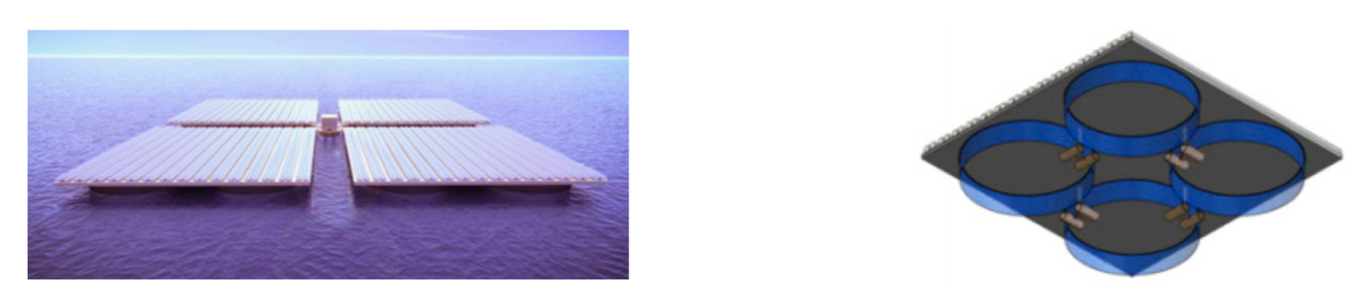
2.4. Floating Thin-Film Photovoltaic Systems

Norwegian Ocean Sun has proposed a floating thin-film photovoltaic system which uses a thin polymer membrane placed on a circular floater to carry the customized PV modules. The membrane system has a longer minimum lifetime than other systems and no environmental impact on the water. The floating thin-film photovoltaic system consists of custom PV modules, double keder, a reinforced membrane, inverters and an AC combiner, and a buoyancy ring. Figure 11 shows is the cross-sectional structure of the system [34].
Thin film offshore PV systems have the following advantages.

2.4.1. Low Theoretical Cost of a Floating PV Installation

The material use for required buoyancy is low, and the concept is simple and fast to install. Using local engineering, procurement, and construction to carry out the installation and logistics of the buoyancy ring reduces the costs further.

2.4.2. Simple, Fast, and Safe Maritime Installation

Maritime installation can easily be achieved with a local workforce in many typical locations, as nuts and bolts are not needed. Moreover, the assembly of photovoltaic modules and electrical components is easy.

2.4.3. Enhanced Efficiency from Direct Water Cooling

In this system, the photovoltaic modules dissipate heat through the thin floating membrane, which is more effective than cooling by air convention. According to experiments done in Singapore, the temperature of modules in air was 63 °C, but the temperature of laminated modules in direct contact with the mat/water was 35 °C. The temperature difference equals to about 10% more PV power output.

2.4.4. Robustness against Wind, Waves, and Currents

Conventional floating solar installations are subject to damages from strong winds; e.g., a system in Japan was caught in 190 km/h winds after typhoon Faxai hit in September 2019 [18]. However, the use of a reinforced membrane can improve the safety of the system. The sea will be smoothed by the flexible surface membrane and the membrane can also minimize the drag from sea currents and wind loads. This could stand winds up to 275 km/h, typhoon class 4, based on CFD analysis [18].
The main parameters of the floating thin-film photovoltaic system are shown in the Table 1 below.
Nagananthini R. [40] shows a comparison of the flexible floating thin-film PV system with that of FPV systems and ground-mounted PV systems in the Malaysian Islands.
The results highlight the high energy generation capacity of the floating thin-film PV system with reduced soiling, PV cell temperature, and shading losses compared to other PV systems. As a result, the increase in annual energy yield by the floating thin-film PV system compared to the pontoon-based FPV system ranges from 0.3 to 13%, whereas it is 2 to 14% higher than the ground-mounted PV system.
A cost analysis was also carried out to assess the economic feasibility of floating thin-film PV systems. The results show that the cost of ground-mounted PV systems is 75% higher than that of FPV systems due to the high cost associated with land acquisition and development. Comparing the cost of FPV and floating thin-film PV systems, the reduced weight of the thin film modules used in floating thin-film PV systems resulted in less mooring lines and anchor costs.
Further, with the carbon footprint analysis, it is evident that the floating thin-film PV system benefits the environment by reducing the carbon emission by up to 14% more than FPV and ground-mounted PV systems.

3. Shortcomings and Challenges

For countries with high population density and limited space, floating solar photovoltaic systems present new opportunities to increase the solar power capacity. Many such nations also have long traditions of working with maritime environments [17]. However, there are still several challenges with offshore FPV before it is ready for full commercial use.
Offshore PV is located in a marine environment with wind, wave, and current loads and is surrounded by other severe sea conditions such as high humidity, high salt fog, strong corrosion, strong lightning, and strong typhoons. Applying present inland water photovoltaic system technology to such conditions could lead to devastation, as in the case of the 7.55 MW PV plant in Japan’s Kawashima area which was destroyed by strong wind gusts and enormous waves [17]. Hence, installing a marine FPV system is still expensive compared to other maritime renewable energy sources, and the associated industry is still in its infancy [17].
Other concerns relate to maintenance issues, such as microorganism attachment, sea salt deposition, bird feces pollution, and lightning strikes [41]. Firstly, algae, marine invertebrates, and other tiny aquatic animals clinging to and gathering on the outer surface of submerged offshore constructions might increase the likelihood of structural corrosion, impacting the overall stability of the structure and raising the cost of system operation and maintenance [42]. Secondly, seawater is limited by its salinity, making it easy for sea salt to accumulate on the surface of the system and speeding up the corrosion [17].
Moreover, a conspicuous artificial offshore FPV system can be considered by birds as a sanctuary in the vast open ocean that can easily attract a lot of birds that could damage components. For example, bird manure, guano, is corrosive due to the presence of uric acid, which can weaken metals. Furthermore, when metals are surrounded by moisture, the ammonium salts in guano can electrochemically react with them to accelerate the corrosion. Finally, it is conceivable that lightning may strike the solar panels directly, harming the machinery, rendering it difficult to produce power, and seriously igniting flames [43].
In addition, there are still the following shortcomings and challenges to be faced [44].
The installation of photovoltaics can lead to reduced penetration of the sun’s rays into the water column, which may affect the growth of aquatic animals and algae, among other things.
Reduced humidity and temperature on the solar panels can result in negative thermal drift that may reduce overall efficiency.
Fishing and other transportation activities may be affected, depending on the chosen location.
Since one of the key components in PV panels is cadmium chloride, which is expensive and enormously toxic, it affects both the manufacturing process and the price of solar panels. Researchers found that seawater contains magnesium chloride, which could replace cadmium chloride.
The panels need to be designed to be waterproof, and in order for them to float, their weight needs to be designed to be lighter, which requires high-cost materials. Installation at sea requires more considerations than installation on the road, which makes the whole installation costly.
The connection of the solar panels and their maintenance in the water and connection to the grid can be a major issue for this type of plant.
To find solutions to the above shortcomings and challenges, development programs are under way. For example, the Ministry of Science and Technology of China is focusing major R & D efforts on inshore photovoltaics with its 14th 5-year plan, including utilizing offshore renewable resources, laying the foundations for future advancement to the deep sea.
In addition, in order to reduce their carbon footprints and their dependance on fossil sources, the European member states plan on building between 140 and 222 GW of new PV power plants by 2030, most of which are in the form of offshore PV plants [45].

4. Conclusions

Future development of offshore PV will increasingly include aquatic PV built on lakes, reservoirs, and dam impoundments. Offshore PV is still a technology field in its infancy, but development work is in-progress to adapt PV systems to offshore/marine environments, including PV modules and understanding the effect of environmental factors on PV systems. Offshore PV faces a range of challenges, such as the variety of harsh and challenging sea conditions, including high humidity, high salt fog, strong corrosion, powerful lightning, and strong typhoons, which need to be overcome. Field experiments and grid-connected operations of offshore PV systems have already started in some developed countries.
Piled fixed offshore PV systems, which are stationary, are one of the main forms of offshore PV systems. The main reason limiting their development is the construction of pile foundations offshore. Currently, such PV systems are being vigorously built in several coastal provinces of China. With the lowering of the seabed, the pile-based PV system has no major advantage over the floating PV, but the floating PV still needs to resist the waves compared to the water-based PV in the land area. Therefore, the current offshore floating PV system is still using wave protection equipment and the PV system is combined with the split design. Floating platform photovoltaic solutions are already a relatively mature solution, and many companies have proposed a variety of floating platforms with different structures and unique advantages. In addition, the combination of PV floating platforms and other industries is also gradually progressing and expanding, and cases of combining offshore PV platforms with other industries such as fisheries and wind power generation are emerging in the future. Compared to other types of floating PV, the advantage of thin-film floating PV is that it can fluctuate with the waves, which can reduce the impact of the waves on the PV system. In addition, the transport and installation of this type of PV system is also unique. The foldable film can reduce the transportation and installation costs to a large extent.
Offshore PV reduces both emissions and land use effects, and its benefits are evident in densely populated areas such Europe and the eastern coast of China. Current technology can already support the construction of offshore photovoltaic, but moving further off the shore to deep ocean conditions will require more progress, e.g., new anti-corrosion materials.

Author Contributions

Conceptualization, J.W. and P.D.L.; methodology, J.W.; validation, J.W.; formal analysis, P.D.L.; investigation, P.D.L.; resources, J.W.; data curation, J.W.; writing—original draft preparation, J.W.; writing—review and editing, P.D.L.; visualization, J.W.; supervision, P.D.L.; project administration, P.D.L.; funding acquisition, J.W. All authors have read and agreed to the published version of the manuscript.

Funding

This research received no external funding.

Informed Consent Statement

Not applicable.

Data Availability Statement

The data presented in this study are available on request from the corresponding author. The data are not publicly available because this is the data that is used in business.

Conflicts of Interest

The authors declare no conflict of interest.

References

  1. Cosemans, V. Expert Consortium Including DEME Explores Pioneering High-Wave Offshore Solar Technology. 18 July 2019. Available online: https://www.deme-group.com/news/expert-consortium-including-deme-explores-pioneering-high-wave-offshore-solar-technology (accessed on 4 August 2022).
  2. Micheli, L.; Talavera, D.L.; Tina, G.M.; Almonacid, F.; Fernández, E.F. Techno-economic potential and perspectives of floating photovoltaics in Europe. Sol. Energy 2022, 243, 203–214. [Google Scholar] [CrossRef]
  3. Gorjian, S.; Minaei, S.; MalehMirchegini, L.; Trommsdorff, M.; Shamshiri, R.R. Applications of Solar PV Systems in Agricultural Automation and Robotics. In Photovoltaic Solar Energy Conversion; Elsevier: Amsterdam, The Netherlands, 2020; pp. 191–235. [Google Scholar]
  4. Crago, C.L.; Koegler, E. Drivers of growth in commercial-scale solar PV capacity. Energy Policy 2018, 120, 481–491. [Google Scholar] [CrossRef]
  5. Garanovic, A. EU Targets 40 GW of Ocean Energy and Other Emerging Technologies by 2050; Offshore Energy: Rotterdam, The Netherlands, 2020. [Google Scholar]
  6. Wang, Z.; Carriveau, R.; Ting, D.S.-K.; Xiong, W.; Wang, Z. A review of marine renewable energy storage. Int. J. Energy Res. 2019, 43, 6108–6150. [Google Scholar] [CrossRef]
  7. Joo, H.J.; Lee, N.H.; Lee, S.W. Floating photovoltaic power generation system. Korean Soc. Adv. Compos. Struct. 2013, 4, 31–39. [Google Scholar]
  8. Smyth, M.; Russell, J.; Milanowski, T. Solar Energy in the Winemaking Industry; Springer: London, UK, 2011. [Google Scholar]
  9. Vo, T.T.E.; Ko, H.; Huh, J.; Park, N. Overview of Possibilities of Solar Floating Photovoltaic Systems in the OffShore Industry. Energies 2021, 14, 6988. [Google Scholar] [CrossRef]
  10. Emiliano, B. Off-Shore PV Project with LCOE of €0.15/kWh Off the Belgian Coast. PV Mag. 2021. Available online: https://www.pv-magazine.com/2021/09/03/off-shore-pv-project-with-lcoe-of-e0-15-kwh-off-the-belgian-coast/ (accessed on 4 August 2022).
  11. Sahu, A.; Yadav, N.; Sudhakar, K. Floating photovoltaic power plant: A review. Renew. Sustain. Energy Rev. 2016, 66, 815–824. [Google Scholar] [CrossRef]
  12. Gorjian, S.; Sharon, H.; Ebadi, H.; Kant, K.; Scavo, F.B.; Tina, G.M. Recent technical advancements, economics and environmental impacts of floating photovoltaic solar energy conversion systems. J. Clean. Prod. 2021, 278, 124285. [Google Scholar] [CrossRef]
  13. Huadong Engineering Corporation Limited; Nanjing Parrott Solar Energy Co.; Southeast University. Floating Photovoltaic Power Generation System. CN202111226822.8, 10 December 2021. [Google Scholar]
  14. Wen, J.B. Shandong: Support offshore wind power, photovoltaic and hydrogen energy development is expected to form a hundred billion investment scale. New Energy Technol. 2022, 4, 19–20. [Google Scholar]
  15. Xu, Z.; Lin, X.Y. Wenzhou Taihan 550 MW fishery and solar power project connected to the grid. Wenzhou Daily, 27 December 2021. [Google Scholar]
  16. Tina, G.M.; Scavo, F.B.; Merlo, L.; Bizzarri, F. Analysis of water environment on the performances of floating photovoltaic plants. Renew. Energy 2021, 175, 281–295. [Google Scholar] [CrossRef]
  17. Oliveira-Pinto, S.; Stokkermans, J. Marine Floating Solar Plants: An overview of potential, challenges and feasibility. Proc. Inst. Civ. Eng.-Marit. Eng. 2020, 173, 120–135. [Google Scholar] [CrossRef]
  18. Solar Energy Research Institute of Singapore; World Bank Group; Energy Sector Management Assistance Program. Where Sun Meets Water: Floating Solar Market Report. 30 October 2018. Available online: https://openknowledge.worldbank.org/handle/10986/31880 (accessed on 4 August 2022).
  19. Bjørneklett, G. Offshore floating solar—A technical perspective. PV Tech Power 2018, 16, 6–9. [Google Scholar]
  20. Boersma, T.; van der Laan, J.; Noorduyn, O.; Mesbahi, M. A Comprehensive Overview of 200+ Global Floating Solar Plants. Available online: https://www.solarplaza.com/channels/future-grid/12067/200-global-floating-solar-plants/ (accessed on 4 August 2022).
  21. Prouvost, B. Hydrelio® Technology Catalog. 5 May 2018. Available online: https://issuu.com/cieletterre/docs/c_t_catalog_hydrelio__technology_20 (accessed on 4 August 2022).
  22. Trapani, K.; Millar, D.L. Proposing offshore photovoltaic (PV) technology to the energy mix of the Maltese islands. Energy Convers. Manag. 2013, 67, 18–26. [Google Scholar] [CrossRef]
  23. Grech, M.; Stagno, L.M.; Aquilina, M.; Cadamuro, M.; Witzke, U. Floating photovoltaic installations in Maltese sea waters. In Proceedings of the 32nd European Photovoltaic Solar Energy Conference and Exhibition, Munich, Germany, 20–24 June 2016; pp. 1965–1968. [Google Scholar]
  24. Zhang, T.F.; Zhang, H.; Sun, L. Analysis of the influence of the shape of floating breakwater on the effect of wave stopping and wave dissipation. Pearl River Water Transp. 2022, 08, 90–94. [Google Scholar]
  25. Wu, X.H. A brief discussion on the design of permeable breakwater pile foundation. Pearl River Water Transp. 2021, 15, 90–91. [Google Scholar]
  26. Sheng, Y.S.; Zhou, Y.R.; Pan, J.N.; Wang, X.G. Research progress and application of floating breakwater. Hydro-Sci. Eng. 2016, 5, 124–132. [Google Scholar]
  27. Sheng, Y.S.; Zhou, Y.R.; Pan, J.N.; Wang, X.G. Experimental study on wave dissipation effect of double floating tank type floating breakwater under different connection methods. In Proceedings of the 18th China Ocean (Shore) Engineering Symposium (Below), Zhoushan, China, 22–25 September 2017; pp. 259–263. [Google Scholar]
  28. Liu, W.J.; Sun, Z.L. A Kind of Circular Floating Breakwater. CN104912028A, 16 September 2015. [Google Scholar]
  29. Rosa-Clot, M.; Tina, G. Submerged and Floating Photovoltaic Systems: Modelling, Design and Case Studies; Elsevier: Amsterdam, The Netherlands; Academic Press: Cambridge, MA, USA, 2018. [Google Scholar]
  30. International Finance Group, Utility-Scale Solar Photovoltaic Power Plants: A Project Developer’s Guide. 4 August 2022. Available online: https://www.ifc.org/wps/wcm/connect/a1b3dbd3-983e-4ee3-a67b-cdc29ef900cb/IFC+Solar+Report_Web+_08+05.pdf?MOD=AJPERES&CVID=kZePDPG (accessed on 4 August 2022).
  31. Walker, A. Best Practices for Operation and Maintenance of Photovoltaic and Energy Storage Systems, 3rd ed.; 4 August 2022. Available online: https://www.nrel.gov/docs/fy19osti/73822.pdf (accessed on 4 August 2022).
  32. Clemons, S.K.C.; Salloum, C.R.; Herdegen, K.G.; Kamens, R.M.; Gheewala, S.H. Life cycle assessment of a floating photovoltaic system and feasibility for application in Thailand. Renew. Energy 2021, 168, 448–462. [Google Scholar] [CrossRef]
  33. Daroen, I. Risk Assessment of Offshore Floating Photovoltaic Systems: Methodology for Technological Risks. Master’s Thesis, Delft University of Technology, Delft, The Netherland, 2021. [Google Scholar]
  34. Eisl, R. HELIOFLOAT—A Floating Lightweight Platform. Institute for Energy Systems and Thermodynamics. 4 August 2022. Available online: https://www.tuwien.at/fileadmin/Assets/dienstleister/forschungsmarketing/messe/Messe_Rueckblick/HM2016/HELIOFLOAT_platform_EN.pdf (accessed on 5 August 2022).
  35. SOLARDUCK. Flexibly Interconnected Semi-Sub Triangular Structures. Artificulated Floating Structure. PCT/EP2020/087842, 2020. [Google Scholar]
  36. Tiong, Y.K.; Zahari, M.A.; Wong, S.F. The Feasibility of Wind and Solar Energy Application for Oil and Gas Offshore Platform. IOP Conf. Ser. Mater. Sci. Eng. 2015, 78, 012042. [Google Scholar] [CrossRef]
  37. Rosebro, J.; Fossil-Fuel Platform Runs on Renewable Energy. 20 April 2006. Available online: http://www.greencarcongress.com/2006/04/fossilfuel_plat.html (accessed on 5 August 2022).
  38. Zhang, J.H.; Liu, X.G.; Gu, Z.J.; Cheng, G.F.; Zhu, H. The ecological economic characteristics of fishery and light complementary and its development direction. J. Fish. China 2022, 46, 1525–1535. [Google Scholar]
  39. Zheng, X.; Zheng, H.; Lei, Y.; Li, Y.; Li, W. An offshore floating wind-solar-aquaculture system: Concept design and extreme response in survival conditions. Energies 2020, 13, 604. [Google Scholar] [CrossRef] [Green Version]
  40. Ravichandran, N.; Ravichandran, N.; Panneerselvam, B. Comparative assessment of offshore floating photovoltaic systems using thin film modules for Maldives islands. Sustain. Energy Technol. Assess. 2022, 53 Pt A, 102490. [Google Scholar] [CrossRef]
  41. Zaini, N.H.; Ab-Kadir, M.Z.A.; Izadi, M. On the effect of lightning on a solar photovoltaic system. In Proceedings of the 2016 33rd International Conference on Lightning Protection (ICLP), Estoril, Portugal, 25–30 September 2016; pp. 1–4. [Google Scholar]
  42. El-Reedy, M.A. Offshore Structure Platform Design. In Offshore Structures; Elsevier BV: Amsterdam, The Netherlands, 2012; pp. 93–211. [Google Scholar]
  43. Fallah, N.; Gomes, C.; Ab Kadir, M.Z.A. Lightning protection techniques for roof-top PV systems. In Proceedings of the 2013 IEEE 7th International Power Engineering and Optimization Conference (PEOCO), Langkawi, Malaysia, 3–4 June 2013; pp. 417–421. [Google Scholar]
  44. Kaymak, M.K.; Şahin, A.D. Problems encountered with floating photovoltaic systems under real conditions: A new FPV concept and novel solutions. Sustain. Energy Technol. Assess. 2021, 47, 101504. [Google Scholar] [CrossRef]
  45. Kougias, I.; Taylor, N.; Kakoulaki, G.; Jäger-Waldau, A. The role of photovoltaics for the European Green Deal and the recovery plan. Renew. Sustain. Energy Rev. 2021, 144, 111017. [Google Scholar] [CrossRef]
Figure 1. Main components of FPV system.
Energies 15 07462 g001
Figure 2. Floating breakwater (a) and pile-permeable breakwater (b).
Energies 15 07462 g002
Figure 3. A standard large-scale floating PV system with major components [32]. Reprinted with permission from Ref. [Life cycle assessment of a floating photovoltaic system and feasibility for application in Thailand]. 2021, Clemons, S.K.C.
Energies 15 07462 g003
Figure 4. Solar Sea floating PV [18]. [Permission of using the figure has been requested from the copyright holder Swimsol].
Energies 15 07462 g004
Figure 5. Floating Solar Park [33]. [Permission of using the figure has been requested from the copyright holder Moss Maritime].
Energies 15 07462 g005
Figure 6. HelioFloat Offshore Platform [34]. [Permission of using the figure has been requested from the copyright holder Dr. Roland Eisl].
Energies 15 07462 g006
Figure 7. Triangular floating platform structure [35]. [Permission of using the figure has been requested from the copyright holder Solarduck].
Energies 15 07462 g007
Figure 8. Wind turbines and solar panels on offshore platform [37]. Reprinted with permission from Ref. [Fossil-Fuel Platform Runs on Renewable Energy]. 2006, Rosebro, J.
Energies 15 07462 g008
Figure 9. Multi-purpose platform combining offshore floating photovoltaic, wind turbine, and aquaculture [39]. Reprinted with permission from Ref. [An offshore floating wind–solar–aquaculture system: Concept design and extreme response in survival conditions]. 2020, Zheng, X.
Energies 15 07462 g009
Figure 10. Hybrid offshore platform structure (OHP) [33]. [Permission of using the figure has been requested from the copyright holder SINN POWER].
Energies 15 07462 g010
Figure 11. The cross-sectional structural diagram of the floating thin-film photovoltaic system.
Energies 15 07462 g011
Table 1. The main parameters of the floating thin-film photovoltaic system.
Diameter 73 mDiameter 51 m
Capacity
(Module dep.)
525–640 kWp230–260 kWp
# of Modules1944848
Smart string
inverters
3 × 185 kWp
1500 V DC/800 V AC
3 × 100 kWp
1500 V DC/400 V AC
Publisher’s Note: MDPI stays neutral with regard to jurisdictional claims in published maps and institutional affiliations.

