Article

Thermal Effect of Cylindrical Heat Sink on Heat Management in LED Applications

1
Department of Mechanical Engineering, Delta State University, Abraka, Oleh Campus, Oleh 334109, Nigeria
2
School of Physics, Engineering and Computer Science, University of Hertfordshire, Hatfield AL10 9AB, UK
3
School of Engineering, Arts, Science and Technology (EAST), University of Suffolk, Ipswich IP4 1QJ, UK
4
Faculty of Engineering and Science, University of Greenwich, Kent ME4 4TB, UK
*
Authors to whom correspondence should be addressed.
Energies 2022, 15(20), 7583; https://doi.org/10.3390/en15207583
Submission received: 16 August 2022 / Revised: 29 September 2022 / Accepted: 9 October 2022 / Published: 14 October 2022
(This article belongs to the Collection Advanced Energy Materials and Research)

Abstract

:
Light Emitting Diode (LED) applications are increasingly used in various microelectronic devices due to their efficient light generation. The miniaturisation of the LED and its integration into compact devices within the weight limit have resulted in excessive heat generation, and inefficient management of this heat could lead to the failure of the entire system. Passive and/or active heat sinks are used for dissipating heat from the system to the environment to improve performance. An ANSYS design modeller and transient thermal conditions were utilised in this study to design and simulate the LED system. The modeller performs its function by utilising the Finite Element Method (FEM) technique. The LED system considered in this work consists of a chip, thermal interface material, and a cylindrical heat sink. The thickness of the Cylindrical Heat Sink (CHS) fins used in the investigation is between 2 mm and 6 mm, whilst ensuring the mass of heat sinks is not more than 100 g. The input power of the LED chip is between 4.55 W and 25.75 W, as required by some original equipment manufacturers (OEMs). A mesh dependency study was carried out to ensure the results were synonymous with what can be obtained practically. The simulation results suggest that the power ratings did not affect the thermal resistance of the CHS. In addition, the thermal resistance increased with the increased thickness of the CHS fin. The efficiencies of the heat sink were found to increase with an increased thickness of the cylindrical fin and the accuracy between the calculated and simulated thermal efficiency ranges from 84.33% to 98.80%. Evidently, the CHS fin of 6 mm thickness is more efficient than the other CHS fins, as depicted in this study.

1. Introduction

Light Emitting Diodes (LEDs) convert electrical energy directly into light and deliver efficient light generation with little waste of electricity in comparison to conventional light sources such as the incandescent and halogen lamps that first convert electrical energy into heat, and then into light [1]. LEDs are increasingly used in domestic and industrial lighting systems, including in lamps for indoor and outdoor use [1]. These LEDs generate heat during operation, and if not properly managed, this heat may lead to performance deterioration and the shortened life of the device [2]. Costa and Lopes [3] suggested an improved radial heat sink for LED lamp cooling for the purpose of increasing the life span of such devices. The failure of devices can be attributed to the accumulation of excess heat in the system. To avoid failure in such devices, heat sinks are introduced. The application of heat sinks with different configurations has been utilised to improve the life of LED applications [4]. Barbosa et al. [5] used a heat sink as the passive heat dissipation device when the design optimisation of a high-powered LED matrix luminaire was investigated, whilst Tang et al. [6] developed an integrated heat sink with a vapour chamber for the thermal management of high-powered LEDs. Typically, heat sinks dispel the heat from the LED device to the environment using the methods of conduction, convection, and radiation. The conduction technique is the most preferred, with the heat sink bonded to the LED chip/chips using Thermal Interface Materials (TIMs), whilst the convection method to dissipate heat occurs between the heat sink and the environment.
Numerical and computational methods have been used to analyse heat sinks (heat sink fins) in microelectronic applications. Sobamobo et al. [7] investigated the impact of Lorentz force on the thermal behaviour of a convective–radiative porous fin using the differential transformation method. Their findings suggested that increases in the magnetic field, porosity, convective, and radiative parameters increase the rate of heat transfer from the fin and consequently the efficiency of the fin is improved. In the analysis conducted by Ekpu [8], ANSYS was used to study the effect of fin arrangement on thermal performance in microelectronic devices and the numerical results were satisfactory. Staliulionis et al. [9] used COMSOL to investigate heat sink efficiency for electronic component cooling applications. Arshad et al. [10], who studied the thermal transmission comparison of nano-fluids over a stretching surface under the influence of a magnetic field, used MATLAB for their analysis. This method of analysis has reduced the costs of experimental work by researchers. However, the need to verify the simulation results with practical work cannot be overemphasised. Considering the study by Ranjith et al. [11], it seems that the heat transfer features of LED modules using passive heat sinks have some advantages such as energy efficiency, performance, versatility, and prolonged life. Furthermore, it was stated that LEDs could only convert about 20–30% of the power supplied to the chip, leaving about 70–80% of the energy being converted into heat that must be dissipated from the system.
The study by Mjallal et al. [12] discussed ways of using Phase Change Materials (PCMs) to improve electronic device heat sinks’ cooling efficiency. They stated that PCM-based heat sinks could efficiently absorb the heat generated by the electronic device, thereby delaying the peak temperature of the device. This absorbed energy is later released when the device is turned off. In their research, two PCMs, salt hydrate and wax, were compared with a heat sink without a PCM. It was inferred that using PCMs will delay the device from reaching its peak temperature by a couple of minutes (approximately 42 min, compared to 10 min for heat sinks without PCM) for a heat flux input of 1250 W/m2. The studies carried out by Salah and Hamida, [13] also adduced a similar pattern and substantiated the finding of Mjallal et al. [12].
In another study by Chu et al. [14] using the LED desk lamp to develop a new heat sink design, they used both simulation and experiment to analyse four different heat sink designs with fins in transverse or longitudinal directions and with or without vents on the heat sink base. Their analysis revealed only about a 4% difference between the experimental and simulation results. However, the researchers adopted a design with 12 vents on both sides of the heat sink base to create a chimney effect through natural convection. The temperature of the LED desk lamp was reduced by about 5 °C based on the novel heat sink design. Based on the material used for the prototype heat sink, the weight of the LED desk lamp and the overall production costs were significantly reduced.
The thermal performance of LED array heat sink using simulation and experimental validation was investigated in [15]. The design and thermal analysis were conducted using natural convection conditions. Their findings suggested that when the number of heat sink fins increased, the thermal resistance and the convection heat transfer coefficient decreased accordingly. Likewise, increasing the height of the heat sink fins reduces the convective heat transfer coefficient and thermal resistance. However, the study indicated that the input power and inlet air could increase the convective heat transfer coefficient and decrease the thermal resistance. A comparison of the experimental and the numerical simulation results suggested that the developed mathematical model could be used to predict the thermal characteristics of LED array heat sinks.
In other applications, such as thermal plants and automobile industries, heat exchangers and radiators are used for energy recovery and heat dissipation. The study conducted by Jamil et al. [16] on energy recovery systems using offset strip-fin compact heat exchangers suggested that the geometry of the fins and fluid velocity are the most critical parameters in managing heat. In another study, the thermal–hydraulic characteristics of gasketed plate heat exchangers as a preheater for thermal desalination systems were investigated [17]. The findings suggest that salinity does not affect the performance of heat exchangers, but fouling resistance is critical to the overall design parameters and cost.
In this study, an improved approach to the thermal management of the heat generated by LED applications is presented involving different combinations of cylindrical heat sink designs. In addition, different power ratings of the LED chips were used in the analysis of the cylindrical heat sinks. The findings from this study are of significance to developing new thermal management solutions for differently rated power LED applications.

2. Materials and Methods

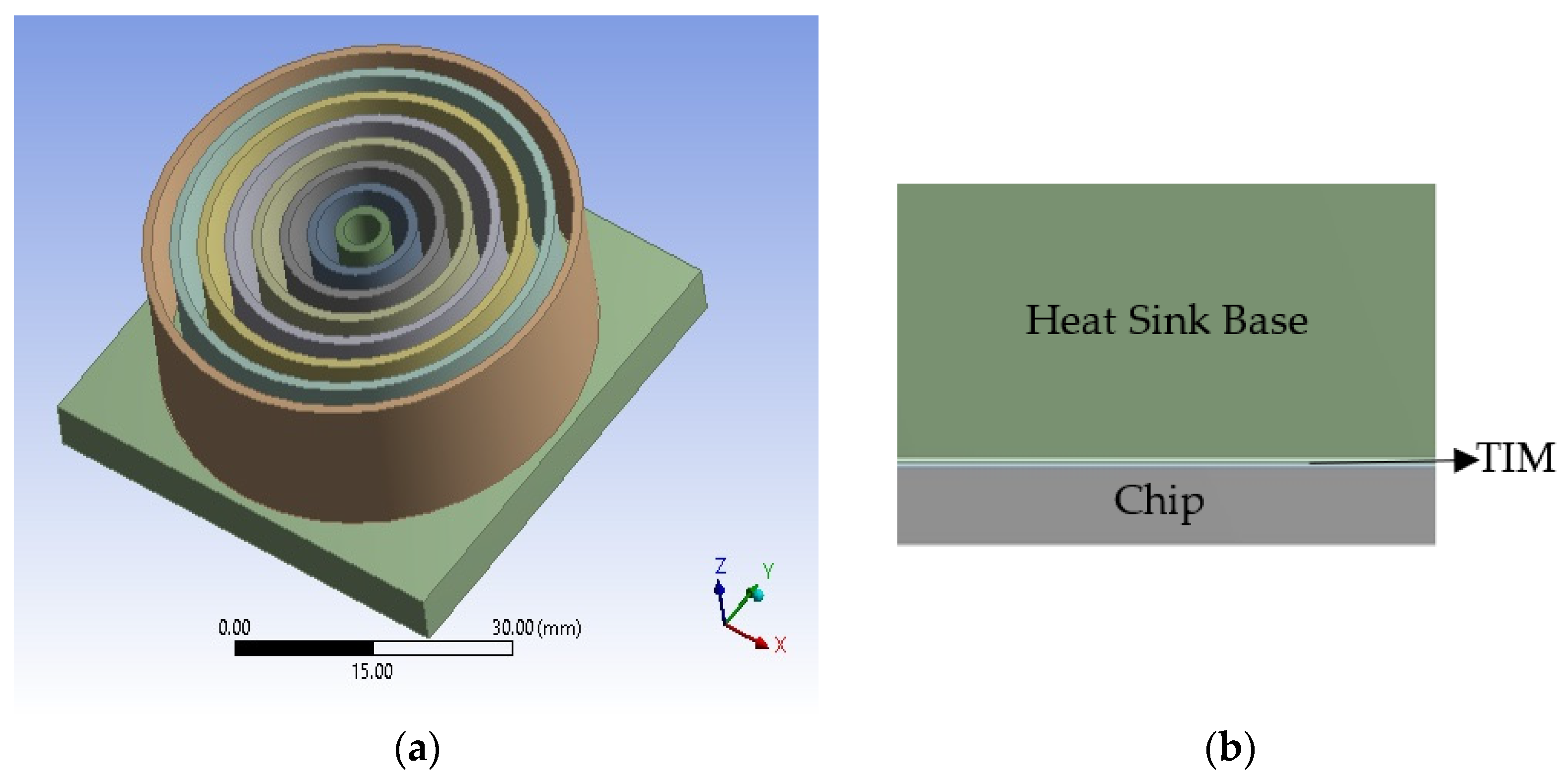
2.1. Description of Model

The model considered in this study is surface mounted, and the assembly comprises the LED chip, thermal interface material, and a cylindrical heat sink. The dimension of the LED chip is 10 mm × 10 mm × 0.5 mm, and the thermal interface material is 10 mm × 10 mm × 0.035 mm. The heat sink is 50 mm × 50 mm × 20 mm. The base thickness is 5 mm, the fin height is 15 mm, and the fin thickness varies from 2 mm to 6 mm with an increment interval of 1 mm. However, the diameter of the fin varied according to the thickness of the fin, whilst the number of cylindrical fins changed according to the thickness of the fins. A schematic diagram of the assembled model is shown in Figure 1a, whilst Figure 1b is showing the expanded view of the silicon chip, the TIM, and the base of the heat sink.

2.2. Materials

The heat sink used in this study is aluminium, the LED chip is silicon, and the thermal interface material is Sn-Ag-Cu (SAC 405) [18]. The properties of the materials used in the simulation work are presented in Table 1. Based on the information presented in Table 1, the mass of the different cylindrical heat sinks designed could be calculated. It is practical evidence that the density of an object is given as:
ρ = M V  
M = ρ V  
where ρ is the density, M is the mass, and V the volume; Table 2 presents the mass for each of the designed cylindrical heat sinks.

2.3. Load and Boundary Conditions

In this study, transient thermal analysis is used to evaluate the thermal characteristics of the different cylindrical heat sinks. The ambient temperature used for the simulation is 22 °C (the temperature is within the range practically acceptable). A natural convection coefficient (20 W/m2K) was applied to the surface of the heat sink. The power supplied through the LED chip is as follows: 4.55 W, 9.7 W, 15.03 W, 20.6 W, and 25.75 W, respectively. The simulation time was set at 3600 s (this time is enough for the heat sink to reach steady state temperature), whilst the simulation step increase was determined automatically by the ANSYS simulation machine after the initial start time, number of steps, and end time were specified. In fact, ANSYS Workbench has the capacity to determine the solver steps to ensure the solution converges. However, if the solution does not converge within the specified conditions, it will flag the results obtained to be checked and settings updated.

Governing Equation

The conduction and convection conditions with the radiation method are assumed negligible and neglected. The heat convection condition is a three-dimensional and incompressible fluid. The fluid in this study is air, which is used for the momentum equation, whilst the density is temperature dependent. The governing simulation equations followed in this study are given as [14,15]:
                                ( ρ u ) x + ( ρ v ) y + ( ρ w ) z = 0 .
Equation (3) represents the continuity equation and the momentum equations for directions x, y, and z are given in Equations (4)–(6), respectively:
u u x + v u y + w u z = 1 ρ P x + v 2 u x 2 + 2 u y 2 + 2 u z 2
u v x + v v y + w v z = 1 ρ P y + v 2 v x 2 + 2 v y 2 + 2 v z 2
u w x + v w y + w w z = 1 ρ P z + v 2 w x 2 + 2 w y 2 + 2 w z 2 + g β ( T T )
The conservation of energy equation for the three-dimensional space is given as:
ρ C p T t = k ( 2 T x 2 + 2 T y 2 + 2 T z 2 ) + Q .  
Equation (7) applies to the subdomains (chip, thermal interface, and heat sink). The working fluid energy equation is given as:
u T x + v T y + w T z = α ( 2 T x 2 + 2 T y 2 + 2 T z 2 ) .
The solid side energy equation is given as:
2 T x 2 + 2 T y 2 + 2 T z 2 = 0 .
Equation (9) is a steady state boundary equation. When this boundary condition is achieved, the solver ends its iteration.
The values u, v, and w represent the x, y, and z directions of the velocity vector; P is the fluid pressure, T is the liquid temperature, g is the acceleration due to gravity, ρ is the fluid density, Cp is the specific heat capacity, β is the coefficient of thermal expansion; T , the ambient temperature, α is the thermal diffusivity, Q is the power output, and k is the thermal conductivity.

3. Results and Discussion

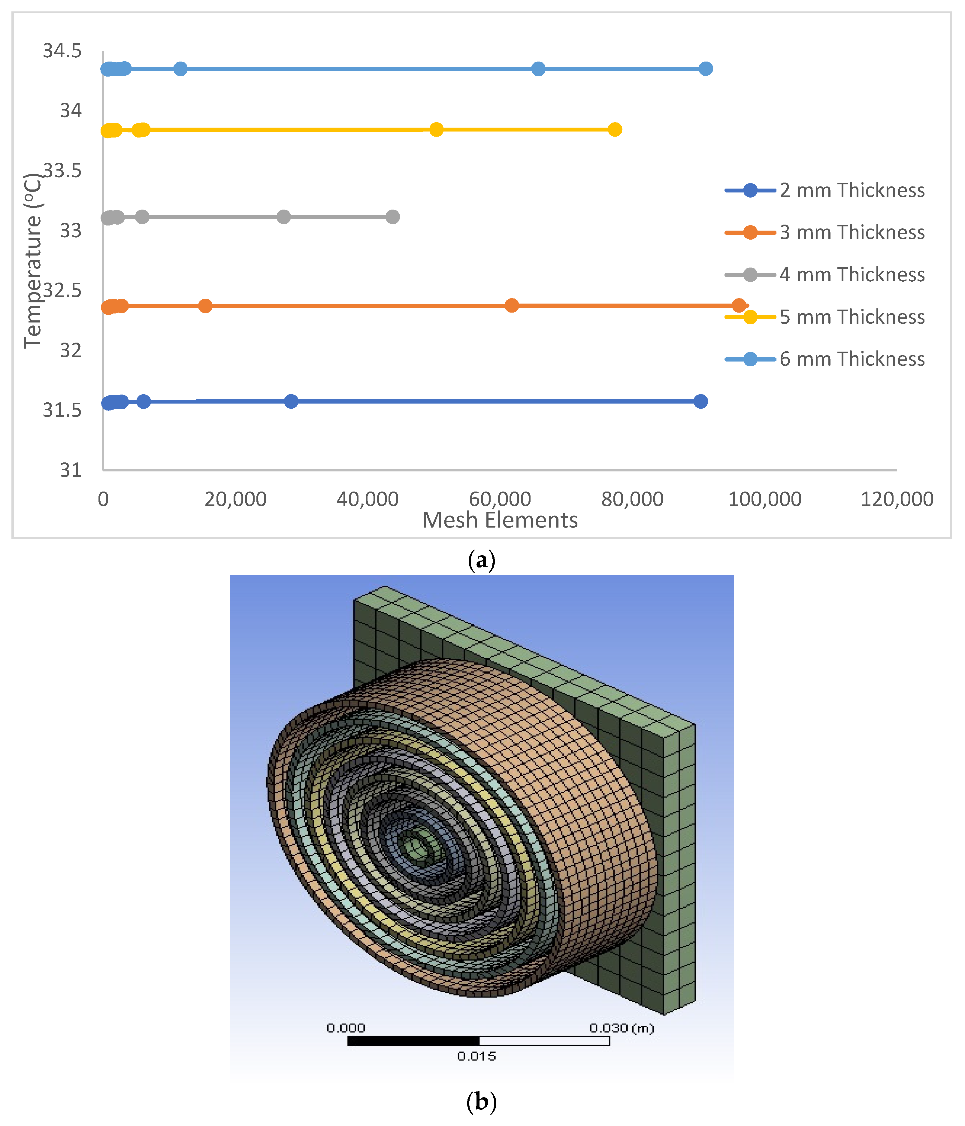
3.1. Mesh Dependency Study

Solving or simulating the model requires that a mesh is carried out to ensure the simulation results are adequate and closely related to what is practically obtainable. Hence, the mesh dependency study carried out by [20] and the mesh sensitivity study carried out by [21] were used as a guide in the present study. According to the work of Okereke and Ling [21], the higher the number of elements, the finer the mesh; this thereby improves the results of the simulation work. In addition, Jeong et al. [22], confirms that the higher the number of grid cells, the better the result obtained. The work also demonstrates the stability of the results as the difference tends to be less than 0.18%. The study carried out by [20] suggested that a mesh within 20% to 40% of the initial size of the model in some applications is adequate to achieve a good simulation result. In this regard, a mesh dependency study was carried out for the present model. Figure 2a presents the mesh dependency of the present model. It was observed that the results were unstable for mesh elements of less than 6000. Therefore, to obtain stable and good results, the mesh used in the present study was above 20,000. However, it is important to note that the number of nodes and elements are functions of the capacity of the simulation machine. In addition, the higher the number of nodes and elements, the longer it takes for the simulation to converge. Figure 2b presents the meshed model with 108,813 nodes and 27,313 elements.

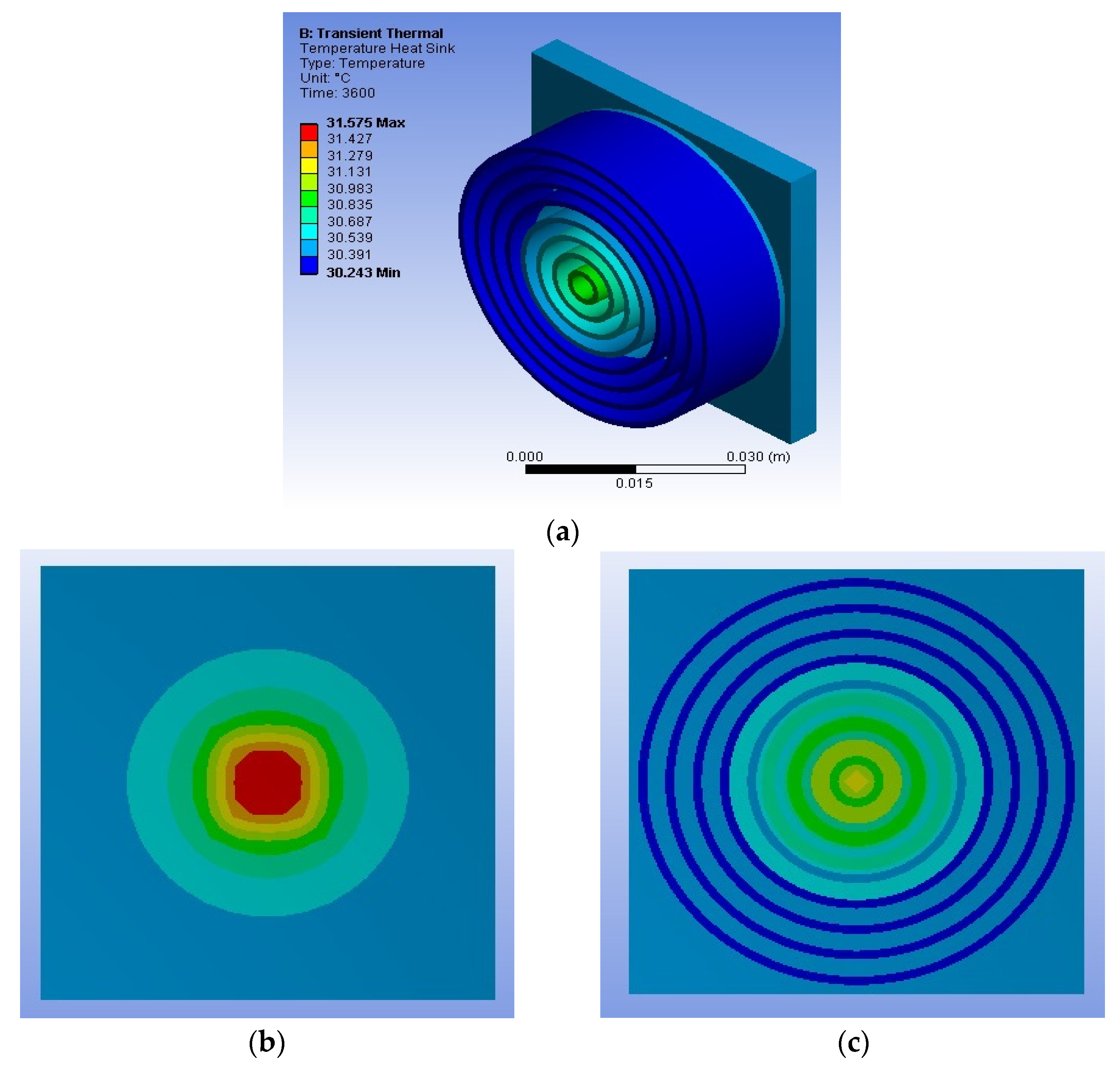
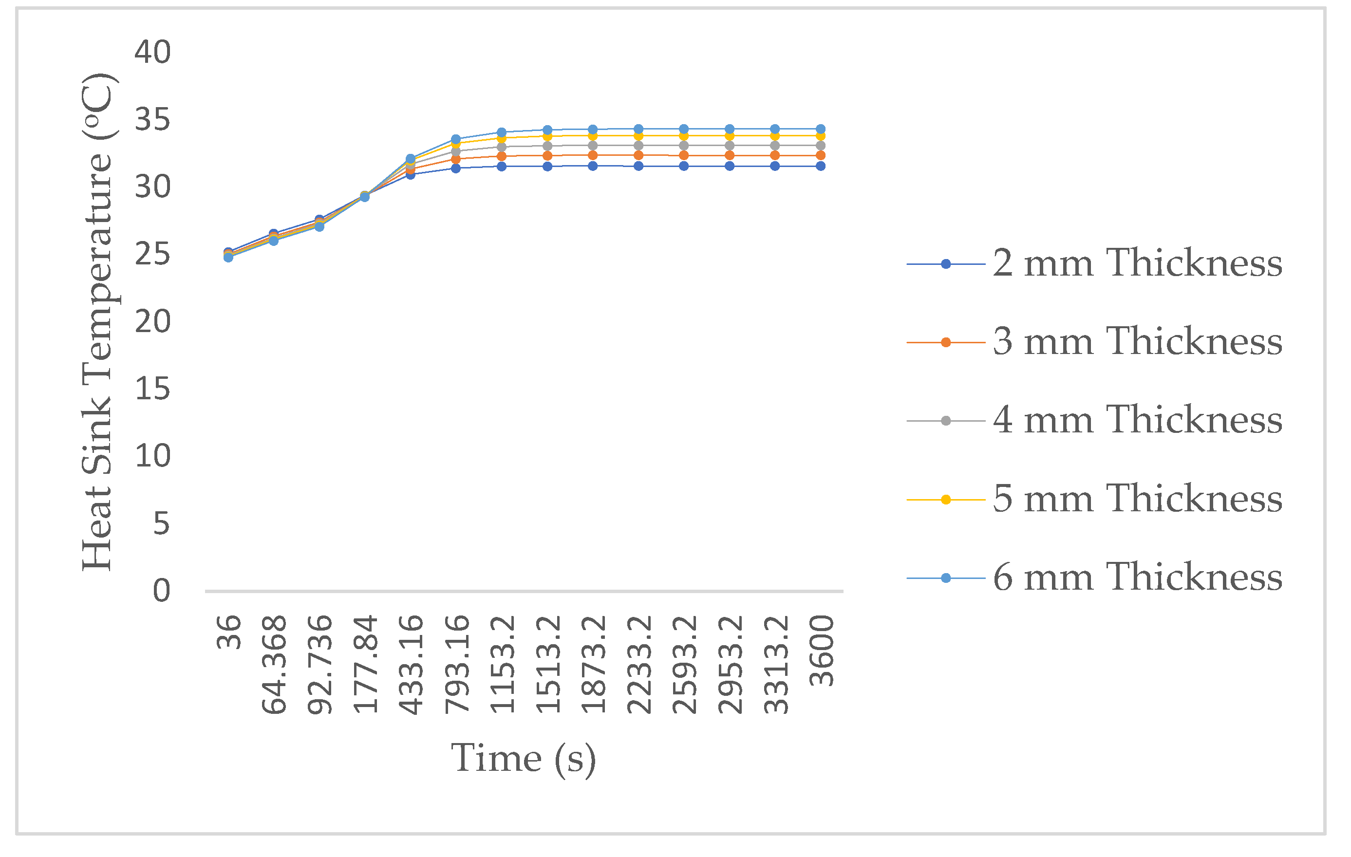
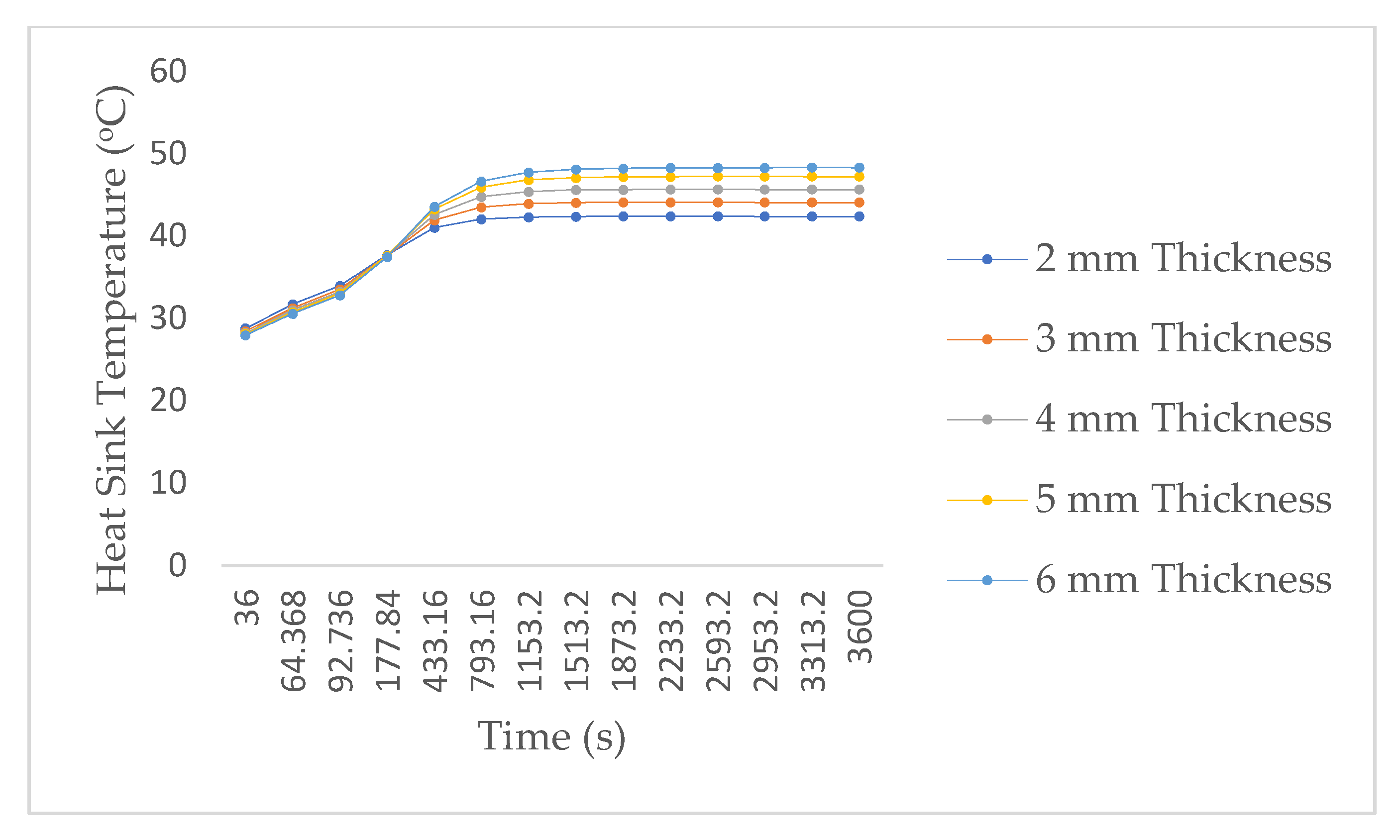
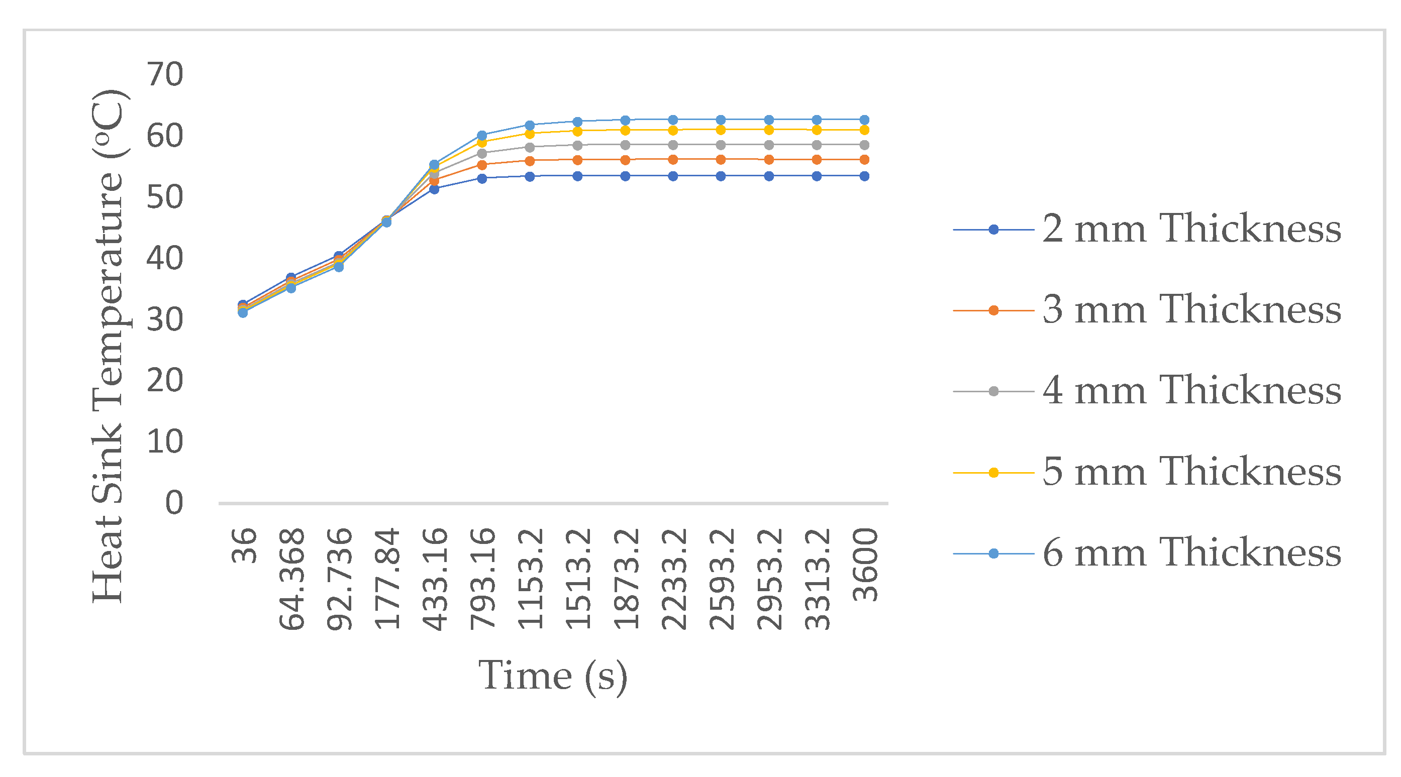
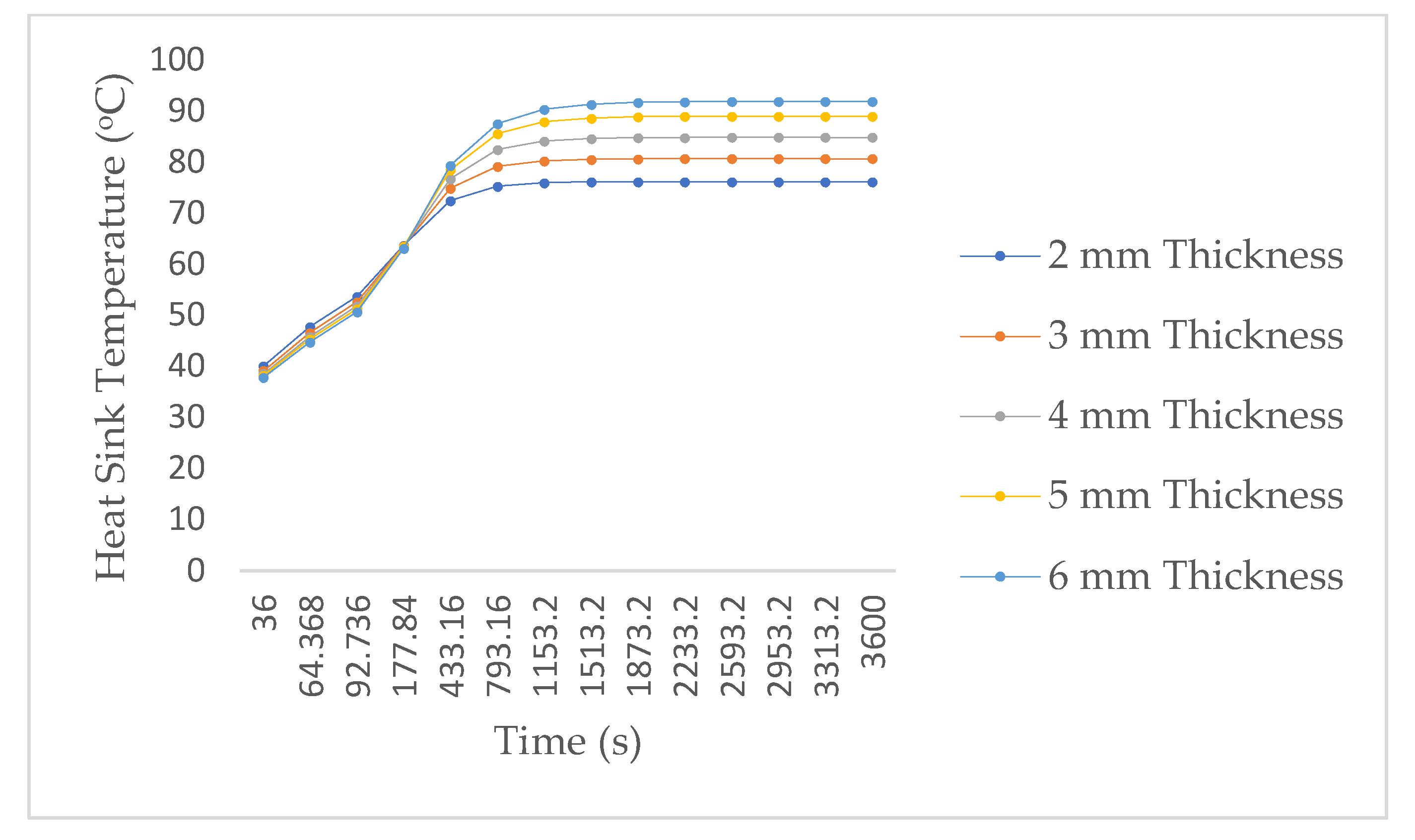
3.2. Effect of Power on Heat Sink Temperature

The temperature contour plot at 4.55 W is presented in Figure 3. In Figure 3a, the isometric view of the cylindrical heat sink is shown, and it is observed that the outer cylindrical fins recorded a lower temperature than the fins closest to the LED chip. This is identified by the blue contour legend in Figure 3. In addition, the red contour legend signifies the part of the model with the highest temperature (this is usually the LED chip because it is the heat source). The isometric and back view of the heat sink shown in Figure 3a,b, respectively, indicate that the temperature contour distribution is concentric. This signifies that heat spreads from the LED chip to the heat sink’s base. This phenomenon confirms that heat is conducted from a hotter source to a colder one within the same environment or medium.
In Figure 4, Figure 5, Figure 6, Figure 7 and Figure 8, the maximum temperatures of the cylindrical heat sink with time at 4.55 W, 9.7 W, 15.03 W, 20.6 W, and 25.75 W for the different cylindrical heat sink fins, respectively, are presented. The graph pattern in Figure 4, Figure 5, Figure 6, Figure 7 and Figure 8 corresponds to the graph pattern presented by Mjallal et al. [12] for temperature against time. This shows that the heat generated by the LED chip was dissipated to the environment through conduction and convection. It also, signifies that the heat generated by the system was effectively managed with acceptable limits to avoid the early failure of the LED system. It is observed from Figure 4, Figure 5, Figure 6, Figure 7 and Figure 8 that the highest and lowest temperatures for the different power ratings were recorded at 6 mm and 2 mm cylindrical heat sink fins, respectively. This could be directly related to the volume of the respective heat sinks, which is a factor of thermal resistance. The bigger the heat sink volume, the longer the temperature travel path. However, this might lead to heat retention in the system but may not necessarily lead to overheating because the heat is gradually dissipated to the environment.
Furthermore, it demonstrated that 6 mm cylindrical heat sink fins could accommodate more heat without affecting the LED application. This is a major objective of this study, and it was achieved with a heat sink having a mass of less than 100 g. The goal of the study was to ensure that the heat sink recommended is less than 100 g. This is because most LED applications are miniaturised and the total weight for some applications is about 500 g including the heat sink device. Again, the maximum temperature from Figure 4, Figure 5, Figure 6, Figure 7 and Figure 8 appears to be approximately stable or constant after 793.16 s for each cylindrical heat sink fin at various power ratings. This means that steady state temperature was reached, and the solution started to converge after 793.16 s. The constant temperatures after some time in different power ratings are observed in the experimental work carried out by Ranjith et al. [11]. In their empirical work, diagonal, cylindrical, and spiral heat sinks were considered for managing heat in LED modules.

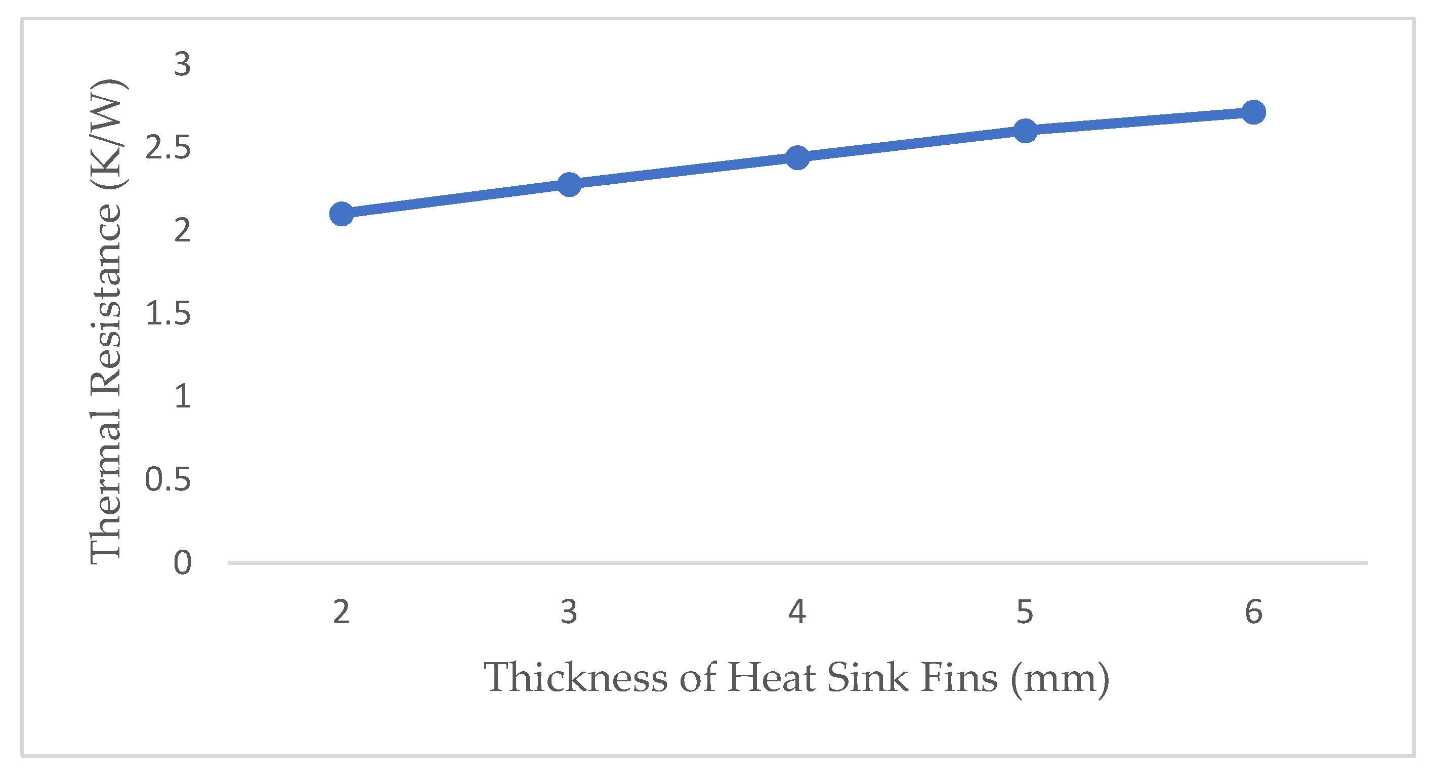
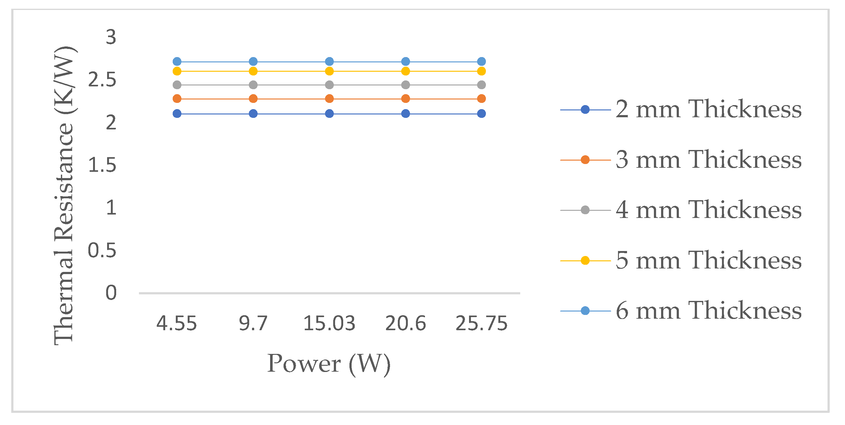
3.3. Effect of Thermal Resistance on the Cylindrical Heat Sink

The thermal resistance of the cylindrical heat sink was calculated using Equation (10):
R = Δ T Q  
where R is the thermal resistance in (K/W), Δ T = T m a x T a m b i e n t and Q is the power in (W). Figure 9 presents the thermal resistances for the different fin thicknesses of the cylindrical heat sinks. As observed in Figure 9, the thermal resistance of the heat sinks slightly increased from 2.104 K/W to 2.715 K/W for a thickness of 2 mm to 6 mm, respectively. This accounts for a 29.04% increment in thermal resistance. This was expected because the higher the volume of a heat sink, the higher the thermal resistance. However, this might not translate to effective heat dissipation or heat removal. Furthermore, Figure 10 presents the thermal resistance of different cylindrical heat sink fin thicknesses at various power ratings. Figure 10 shows that the thermal resistance at 2 mm, 3 mm, 4 mm, 5 mm, and 6 mm are approximately 2.104 K/W, 2.28 K/W, 2.442 K/W, 2.603 K/W, and 2.715, respectively, for different power ranges. In addition, it was also observed that the power ratings of the LED chip did not impact negatively on the thermal resistance of the cylindrical heat sink. In other words, at 2 mm cylindrical heat sink thickness, the thermal resistance was approximately the same for 4.55 W, 9.7 W, 15.03 W, 20.6 W, and 25.75 W. Evidently, a similar trend was observed for the other thicknesses studied with our approach.

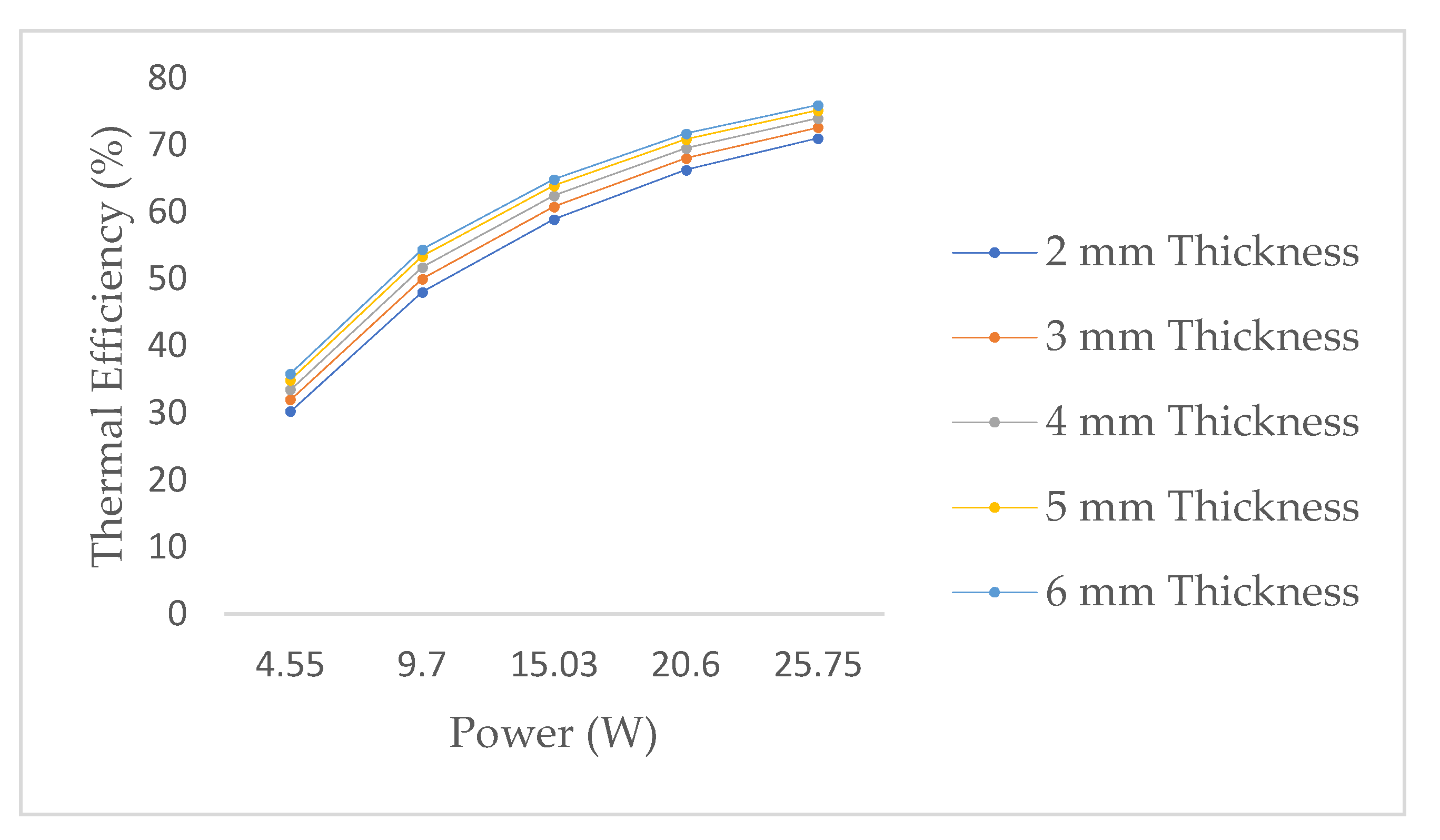
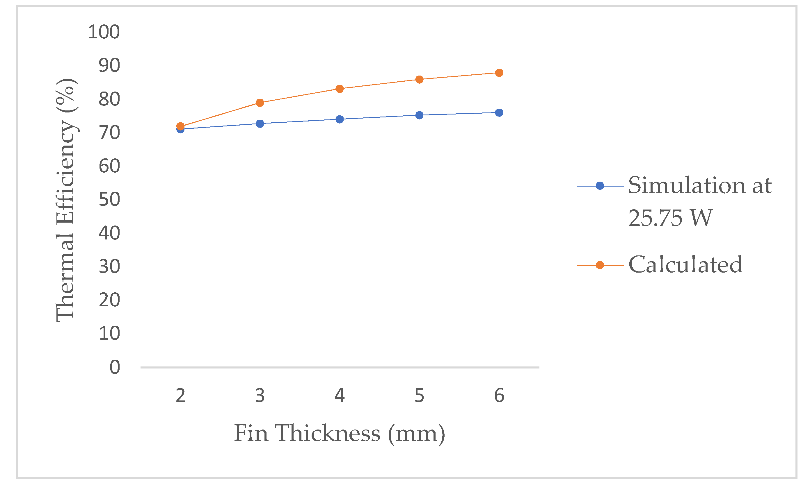
3.4. Thermal Efficiency Analysis

The thermal efficiency calculations of the cylindrical heat sink are analysed and presented in Equations (11)–(13). The simulation thermal efficiency is given as:
T h e r m a l   E f f i c i e n c y   ( η T ) = 1 T a T m a x  
whilst the calculated thermal efficiency is given as [23]:
T h e r m a l   E f f i c i e n c y   ( η T ) = tan h ( m L c ) m L c  
where   m L c = 2 h f L f K t f   .
The T a represents the ambient temperature, T m a x , the temperature maximum of the heat sink, hf, the convection coefficient of the cylindrical heat sink fins; L f denotes the height of the cylindrical heat sink fin and t f , the thickness of the cylindrical heat sink fin. In Figure 11, the thermal efficiency at different thicknesses for different power inputs is shown to follow a similar pattern (increasing with power). It is observed that the thermal efficiency increased with the increased power input for the different cylindrical heat sink fin thicknesses. This is valid since the power inputs had no effect on the thermal resistance of the heat sink. This meant that as the power is increased, the heat transfer rate is increased, thereby increasing the thermal efficiency. The thermal efficiency is a factor of how fast heat is removed from the system to the environment. Therefore, a high heat transfer rate will improve the system, whilst a slow heat transfer rate could lead to heat retention and the possible failure of the system. As shown in Figure 12, the comparison between the calculated and simulated thermal efficiencies at a power rating of 25.75 W is presented. The calculated and simulated thermal efficiencies were observed to increase with increased cylindrical heat sink fin thickness (this is a function of the volume). According to Wakefield-Vette [24], the efficiency of fins will increase when the fin thickness increases; this is observed in Figure 11 and Figure 12. At 6 mm, 5 mm, 4 mm, 3 mm, and 2 mm thickness, the calculated thermal efficiency was higher than the simulated thermal efficiency with 15.67%, 14.20%, 12.27%, 8.58%, and 1.2%, respectively. Therefore, the accuracy between the calculated and simulated thermal efficiency ranges from 84.33% to 98.80%. It could be contingent that an increase in the cylindrical heat sink thickness may cause the calculated thermal efficiency to further drift away from the simulated thermal efficiency.

4. Conclusions

In this study, we have demonstrated the thermal impact of a cylindrical heat sink fin on the management of heat in LED applications with an improved technique using different cylindrical configurations, thicknesses, and power ratings to analyse the heat dissipation effects. The mesh dependency study suggested that adequate meshing was employed to achieve the desired temperature values. The findings suggest that a cylindrical heat sink fin with a 6 mm thickness and a mass of 81.13 g is more efficient than a cylindrical heat sink fin with lesser thickness, despite having a slightly higher thermal resistance. This could be because the higher cylindrical heat sink fin thickness accommodates more heat without causing failure to the LED application. Furthermore, the power ratings of the LED chips were found to have no effect on the thermal resistance of the heat sink investigated. The thermal efficiency of the heat sink was high for the increased volume of the cylindrical heat sink. Likewise, high thermal efficiency was evident in the 6 mm thick heat sink. Additionally, it was shown in this work that the LED performance in electronic circuits could be significantly improved with the choice of the cylindrical heat sink fin considered during the assembly process. Finally, future work will involve the investigation of other types of heat sink configurations and the different materials used in LED systems. This will help to give better information on heat management in microelectronic devices.

Author Contributions

Editorial coordination and papers evaluation M.E., E.A.O., F.N. and J.E.N. All authors have read and agreed to the published version of the manuscript.

Funding

This research received no external funding.

Data Availability Statement

Not applicable.

Acknowledgments

The authors would like to thank the anonymous reviewers for their valuable comments and suggestions to improve the quality of the paper. Finally, Felix Ngobigha would also like to acknowledge the support of the School of Engineering, Arts, Science and Technology (EAST), University of Suffolk, UK with the article processing charge.

Conflicts of Interest

The authors declare no conflict of interest.

Nomenclature

Cpconstant pressure specific heat [J/(kg.°C)]
ggravitational acceleration [m/s2]
hfthe convection coefficient
kthermal conductivity [W/(m.°C)]
Lfthe height of fin [m]
Mmass [kg]
nnumber of fins
ppressure [Pa]
Qheat flow/power [W]
Rthermal resistance [°C/W]
tfthe thickness of fin
Ttemperature [°C]
Tthe ambient temperature
u, v, wCartesian velocity components [m/s]
x, y, zCartesian coordinates [m]
Vthe volume [m3]
Greek symbols
αthermal diffusivity [m2/s]
βcoefficient of thermal expansion [1/K]
ρdensity [kg/m3]

References

  1. Todorov, D.G.; Kapisazov, L.G. Led Thermal Management. Electronics 2008, 2008, 139–144. [Google Scholar]
  2. Buergel, E. Design of LEDS—Heat Management Challenge. Auto Tech. Rev. 2012, 1, 40–43. [Google Scholar] [CrossRef]
  3. Costa, V.A.F.; Lopes, A.M.G. Improved Radial Heat Sink for LED Lamp Cooling. Appl. Therm. Eng. 2014, 70, 131–138. [Google Scholar] [CrossRef]
  4. Ekpu, M.; Bhatti, R.; Okereke, M.I.; Mallik, S.; Otiaba, K.C. Prediction and Optimization of Design Parameters of Microelec- tronic Heat Sinks. J. Emerg. Trends Eng. Appl. Sci. 2013, 4, 493–500. [Google Scholar]
  5. Barbosa, J.; Simon, D.; Calixto, W. Design Optimization of a High Power LED Matrix Luminaire. Energies 2017, 10, 639. [Google Scholar] [CrossRef] [Green Version]
  6. Tang, Y.; Lin, L.; Zhang, S.; Zeng, J.; Tang, K.; Chen, G.; Yuan, W. Thermal Management of High-power LEDs based on Integrated Heat Sink with Vapor Chamber. Energy Convers. Manag. 2017, 151, 1–10. [Google Scholar] [CrossRef]
  7. Sobamowo, M.G.; Alaribe, K.C.; Adeleye, A.O. A Study on the Impact of Lorentz Force on the Thermal Behaviour of a Convective-Radiative Porous Fin using Differential Transformation Method. Int. J. Mech. Dyn. Anal. 2020, 6, 45–59. [Google Scholar]
  8. Ekpu, M. Effect of Fins Arrangement on Thermal Performance in Microelectronics Devices. J. Appl. Sci. Environ. Manag. 2018, 22, 1797–1800. [Google Scholar] [CrossRef]
  9. Staliulionis, Z.; Zhang, Z.; Pittini, R.; Andersen, M.A.E.; Tarvydas, P.; Noreika, A. Investigation of Heat Sink Efficiency for Electronic Component Cooling Applications. Elektron. IR Elektrotechnika 2014, 20, 49–54. [Google Scholar] [CrossRef] [Green Version]
  10. Ashad, M.; Karamti, H.; Awrejcewicz, J.; Grzelczyk, D.; Galal, A.M. Thermal Transmission Comparison of Nano-fluids over Stretching Surface under the Influence of Magnetic Field. Micromachines 2022, 13, 1296. [Google Scholar] [CrossRef]
  11. Ranjith, P.; Manimaran, A.; Praveen, A.S.; Ramesh, T. Experimental investigation of heat transfer characteristics of LED module using passive heat sinks. Int. J. Ambient. Energy 2018, 41, 1209–1213. [Google Scholar] [CrossRef]
  12. Mjallal, I.; Farhat, H.; Hammoud, M.; Ali, S.; Assi, I. Improving the Cooling Efficiency of Heat Sinks through the use of Different Types of Phase Change Materials. Technologies 2018, 6, 5. [Google Scholar] [CrossRef] [Green Version]
  13. Salah, S.B.; Hamida, M.B.B. Alternate PCM with air cavities in LED heat sink for transient thermal management. Int. J. Numer. Methods Heat Fluid Flow 2019, 29, 4377–4393. [Google Scholar] [CrossRef]
  14. Chu, L.; Chang, W.; Huang, T.H. A Novel Heat Sink Design and Prototyping for LED Desk Lamps. Math. Probl. Eng. 2015, 1, 1–8. [Google Scholar] [CrossRef] [Green Version]
  15. Wengang, H.; Lulu, W.; Zongmin, Z.; Yanhua, L.; Mingxin, L. Research on simulation and experimental of thermal performance of LED array heat sink. Procedia Eng. 2017, 205, 2084–2091. [Google Scholar] [CrossRef]
  16. Jamil, M.A.; Goraya, T.S.; Rehman, A.U.; Yaqoob, H.; Ikhlaq, M.; Shahzad, M.W.; Zubair, S.M. A comprehensive design and optimization of an offset strip-fin compact heat exchanger for energy recovery systems. Energy Convers. Manag. X 2022, 14, 100191. [Google Scholar]
  17. Jamil, M.A.; Din, Z.U.; Goraya, T.S.; Yaqoob, H.; Zubair, S.M. Thermal-hydraulic characteristics of gasketed plate heat exchangers as a preheater for thermal desalination systems. Energy Convers. Manag. 2020, 205, 112425. [Google Scholar] [CrossRef]
  18. Ekpu, M.; Bhatti, R.; Okereke, M.I.; Mallik, S.; Otiaba, K. Fatigue life of lead-free solder thermal interface materials at varying bond line thickness in microelectronics. Microelectron. Reliab. 2014, 54, 239–244. [Google Scholar] [CrossRef]
  19. Ekpu, M.; Bhatti, R.; Okereke, M.I.; Mallik, S.; Otiaba, K. The effect of thermal constriction on heat management in a microelectronic application. Microelectron. J. 2014, 45, 159–166. [Google Scholar] [CrossRef]
  20. Ekpu, M. Finite Element Analysis of the Effect of Fin Geometry on Thermal Performance of Heat Sinks in Microelectronics. J. Appl. Sci. Environ. Manag. 2019, 23, 2059–2063. [Google Scholar] [CrossRef]
  21. Okereke, M.I.; Ling, Y. A computational investigation of the effect of three-dimensional void morphology on the thermal resistance of solder thermal interface materials. Appl. Therm. Eng. 2018, 142, 346–360. [Google Scholar] [CrossRef]
  22. Jeong, J.; Hah, S.; Kim, D.; Lee, J.H.; Kim, S. Thermal analysis of cylindrical heat sinks filled with phase change material for high-power transient cooling. Int. J. Heat Mass Transf. 2020, 154, 119725. [Google Scholar] [CrossRef]
  23. Incropera, F.P.; Dewitt, D.P. Introduction to Heat Transfer, 3rd ed.; John Wiley and Sons: New York, NY, USA, 1996; pp. 1–801. [Google Scholar]
  24. Wakefield-Vette. Heat Sink Design Facts and Guidelines for Thermal Analysis. Available online: https://www.digikey.com/en/pdf/w/wakefield-thermal-solutions/heat-sink-design-for-thermal-analysis (accessed on 15 February 2022).
Figure 1. (a) Geometry of the developed model (b) Expanded view showing components.
Energies 15 07583 g001
Figure 2. (a) Mesh dependency study of the present model. (b) Meshed with 108,813 nodes and 27,313 elements.
Energies 15 07583 g002
Figure 3. Temperature contour plot at 4.55 W: (a) Isometric view of the heat sink, (b) Back view of the heat sink, and (c) Front view of the heat sink.
Energies 15 07583 g003
Figure 4. Temperature plot of heat sink at 4.55 W.
Energies 15 07583 g004
Figure 5. Temperature plot of heat sink at 9.7 W.
Energies 15 07583 g005
Figure 6. Temperature plot of heat sink at 15.03 W.
Energies 15 07583 g006
Figure 7. Temperature plot of heat sink at 20.6 W.
Energies 15 07583 g007
Figure 8. Temperature plot of heat sink at 25.75 W.
Energies 15 07583 g008
Figure 9. Thermal Resistance of Heat Sink.
Energies 15 07583 g009
Figure 10. Thermal resistance relative to the power input.
Energies 15 07583 g010
Figure 11. Thermal efficiency relative to the power input.
Energies 15 07583 g011
Figure 12. Comparison between simulation and calculated efficiency.
Energies 15 07583 g012
Table 1. Properties of materials [4,19].
MaterialDensity (kg/m3)Thermal Conductivity (W/mK)Specific Heat (J/kgK)
Aluminium2689237.5951
Silicon2330148712
SAC 405744062236
Table 2. Mass of different cylindrical heat sinks.
Heat Sink Fin Thickness (mm)Number of FinsDensity (kg/m3)Volume of Heat Sink (mm3)Mass of Heat Sink (g)
28268922,301.6959.97
37268925,117.4867.54
46268927,202.6973.15
55268928,698.977.17
65268930,171.4681.13
Note: The volume (12,500 mm3) of the heat sink base is added to the volume of the heat sink.
Publisher’s Note: MDPI stays neutral with regard to jurisdictional claims in published maps and institutional affiliations.

