Article

Measurement-Based Stiff Equation Methodology for Single Phase Transformer Inrush Current Computations

1
Department of Electrical Engineering and Computer Science, Faculty of Electrical Engineering, Silesian University of Technology, Akademicka Street 10, 44-100 Gliwice, Poland
2
Department of Drive Automation and Robotics, Faculty of Electrical Engineering, Automatic Control and Informatics, Opole University of Technology, Prószkowska Street 76, 45-272 Opole, Poland
3
Department of Electrical and Power Engineering, Faculty of Electrical Engineering, Automatics, Computer Science and Biomedical Engineering, AGH University of Science and Technology, A. Mickiewicza Avenue 30, 30-059 Kraków, Poland
*
Authors to whom correspondence should be addressed.
Energies 2022, 15(20), 7651; https://doi.org/10.3390/en15207651
Submission received: 20 September 2022 / Revised: 10 October 2022 / Accepted: 12 October 2022 / Published: 17 October 2022
(This article belongs to the Special Issue Power System Simulation and Modeling)

Abstract

:
The present paper describes the research on the mechanism of inrush current formation in a modern single-phase transformer, in which the insulation system must withstand the stresses arising during these transient states. A complete and measurement-verified method for determining the transformer inrush current waveforms and other signals (e.g., fluxes and voltages) is developed. This method makes it possible to determine a steady state solution. However, on account of the electromagnetic phenomena, the solving process is long. To analyze the transient dynamic response of the tested transformer, a nonlinear model was assumed, from which the stiff differential equations were derived. The simulation analyses were performed using dedicated software written in C# with the original implementation of the five-stage Radau IIA algorithm selected from the known variants of the Runge–Kutta implicit methods. The calculations were based on the measurement waveforms recorded during transient (switch-on) and steady-state states when the transformer was not loaded. The full magnetization curve of the core sheets of the tested transformer with an original implementation of the polynomial fitting mechanism was applied. As a representative example and for the purposes of experimental verification of numerical tests, the worst case scenario for switch-on of an unloaded transformer was applied (switch-on is performed when the supplied voltage is zero). Phenomena related to the obtained experimental results, such as saturation and hysteresis, are discussed as well.

1. Introduction

Transformers undoubtedly play an important role in all electricity transmission and distribution systems. They are of key importance in the processes of conversion and use of electricity. For this reason, transformers and their design, properties, and parameters significantly affect the structure and computational complexity of models of power systems and networks [1]. This statement applies to the analysis of both steady and transient operating states of systems and networks. This applies in particular to situations where the analysis of models should take into account nonlinearities occurring in their individual elements.
Due to the long technical history of practical application and its importance in the power system and networks, the transformer is one of the best recognized and analyzed electrical devices. This is because the principle of its operation covers both electrical and magnetic issues, which additionally extend to the problems of nonlinear systems (resulting, among others, from the hysteresis effect of the transformer core). Considerations and analyses of phenomena occurring in transformers become particularly complex when their dynamics are taken into account. Continuous growth and development of the possibilities and tools of numerical modeling of these phenomena demand corresponding progress in experimental work. These phenomena are used to obtain measurement data to verify the initial conditions and the results of numerical calculations in the outlined problem areas [2,3,4].
In operational practice, a transformer is often switched on in unloaded state. In such states, dynamic phenomena of different nature and time scales take place within it.
Due to the complex interactions of electromagnetic and nonlinear hysteresis phenomena, which result in thermal and electromechanical effects, the occurrence of most transient phenomena can cause significant internal stresses in the transformer. The accompanying overcurrents and overvoltages (with different time characteristics) may have a destructive effect on both the transformer’s structural elements (windings, insulation system) and on the devices cooperating with the transformer in the common electrical network. The effect can then cause further disruptions, including ferroresonance, voltage dips, etc. [5,6,7].
The problem of modeling transient states accompanied by switching the transformer to no-load operation remains open, and research in this area is being undertaken by research groups around the world [8,9,10]. Both electrical and mechanical aspects as well as secondary phenomena such as, e.g., ferroresonance, have been the subject of analyses and dissertations [6,11,12,13]. For many years the latter problem has been the subject of investigations by the authors [14,15,16]. The research problem addressed in this paper is an important element in the ongoing study of dynamic and emergency states in the power system.
The differential equations describing the behavior of a transformer when it is switched on without load belong to the so-called stiff problems. As shown in [17], this applies especially to modern transformers due to improvements in the parameters of the materials used for their production (e.g., an increase in the maximum permissible magnetic flux density). Significant progress in the field of producing sheets for the transformer core has resulted in a reduction in the values of core losses and no-load currents. This has resulted in increased stiffness of the differential equations describing the changes in the magnetic flux and current in these devices, as well as in the value of the current pulse itself when the transformer is switched on. The transformer insulation system must be designed to withstand the stresses created during these transients. Modeling of this phenomenon can be used to predetermine these stresses, and the problem may become solvable through the use of implicit Runge–Kutta methods in numerical calculations [18].
The present paper presents an original and experimentally verified methodology along with results from calculating the dynamic states of a single-phase transformer switched to no-load operation. The method enables the analysis of transients occurring in the transformer and the steady state of no-load operation in the long run. The basis for the verification of the calculations were measurements in both steady and transient states made for several different single-phase transformers. This paper presents the results of the analyses of one of them.
In Section 2, divided into subsections, the model of the transformer is described, the equations describing the transient response are presented, and the nonlinear I μ ( Ψ ) dependency is introduced. In the final subsection of Section 2, an efficient obtainment of the steady state is analyzed. Section 3 discusses the difficulties that arrive from the stiffness of the differential equations. In Section 4, the original methodology for the computation of the dynamics and the steady state is depicted through a detailed diagram. Section 5 discusses the measurement side of the study. The computation results and error analysis are described in Section 6. The conclusions are provided in Section 7. Finally, Appendix A contains the manufacturing data of the studied transformer along with the symbol descriptions.

2. Single-Phase Transformer Model with Nonlinear Characteristics of the Ferromagnetic Core

We have adopted the well-recognized and widely-known Steinmetz model (Figure 1) [19] for this investigation. Its compliance with engineering standards and implementation popularity are consistent with the general concept of developing an engineer-friendly method. Moreover, this model is suitable for the current application while at the same time remaining open to further scientific experiments, for instance, in terms of using alternative descriptions of a ferromagnetic core coil, e.g., using the models described in [20]. The strong point of the model is the possibility of updating the model parameters. Due to long-term operation, present-day transformer parameters may differ from those provided by manufacturer (i.e., data from rating plates and sheet characteristics, including the dualism H ( B ) vs I μ ( Ψ ) in the magnetic description). Thanks to the model construction, unknown or uncertain parameters can be estimated using a range of implemented numerical instruments.
Another and equally important point is that we have assumed that the measured and recorded voltage and current waveforms of the transformer in its transient and steady states constitute the basis for all calculations.
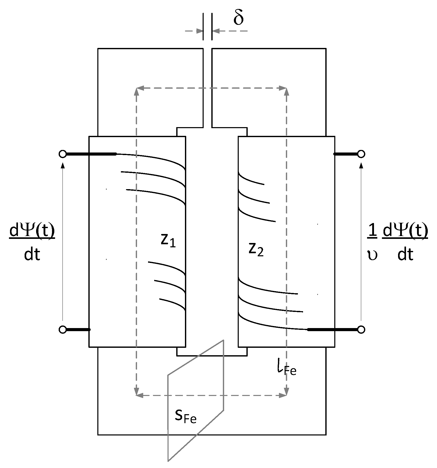
The standard symbols widely used in the literature are recalled in the presented equations and applied in the transformer model (Figure 2). For details regarding the nomenclature, see Table A1 in Appendix A.
The tested transformer is a single-phase unit with a rated power of 1600 VA and voltages of 230/400 v/v. For the studied device, design data such as the geometrical dimensions of the core, the transformer turn ratio, and the H ( B ) characteristic of the sheets used in the core construction were known. Due to the fact that the device had been in continuous operation for more than a year, there was a reasonable suspicion that its parameters might show deviations from the catalog data. In order to avoid errors in the research, an assumption was made as to the necessity of their experimental verification and, in case of any discrepancies, the necessary correction.
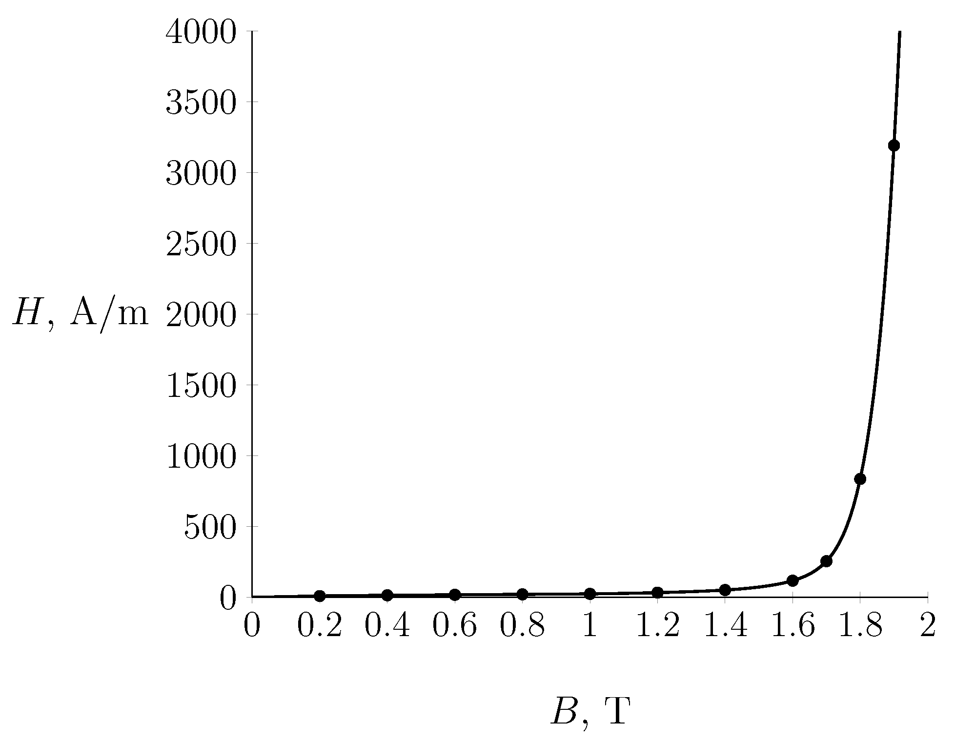
The manufacturer’s characteristics for the transformer laminations of the tested transformer [21] are shown in Figure 3. A list of the remaining manufacturer’s parameters and their values is included in Table A2 in Appendix A.
Using the proposed method and due to the anticipated existence of a relationship between the magnitude of the inrush current pulse and the internal impedance of the power source [17], the power supply network was modeled as well. The network model parameters were estimated on the basis of system data obtained from the Distribution System Operator, then verified in the course of subsequent experiments.

2.1. Modeling of Unloaded Transformer Dynamics

The losses in the ferromagnetic core of the transformer for modeling the coil by a resistor R F e can be written as
d Ψ ( t ) d t = R F e i F e ( t ) .
Starting from Kirchhoff’s first law (Figure 1)
i F e ( t ) = i 1 ( t ) i μ ( t )
and expressing the current i F e ( t ) by the derivative of the flux linkage, then considering the nonlinear dependence of I μ ( Ψ ) , relation (1) takes the form
d Ψ ( t ) d t = R F e i 1 ( t ) R F e I μ ( Ψ ( t ) ) .
From the balance of voltages on the primary side of the transformer, the following relation can be derived:
e ( t ) ( L s + L s 1 ) d i 1 ( t ) d t ( R s + R s 1 ) i 1 ( t ) d Ψ ( t ) d t = 0 .
Equation (4) shows the state variables of a single-phase transformer under no-load conditions
X ( t ) = [ x 1 ( t ) , x 2 ( t ) ] T = [ i 1 ( t ) , Ψ ( t ) ] T .
The differential Equations (3) and (4) derived from the scheme in Figure 1 form the basis for the study of the dynamics of a nonlinear transformer under no-load conditions. Expressed in the normal form, they are provided by
d x 2 ( t ) d t = R F e x 1 ( t ) R F e I μ ( x 2 ( t ) ) = f 2 ( X ( t ) , t )
d x 1 ( t ) d t = 1 L s + L s 1 ( ( R s + R s 1 ) x 1 ( t ) f 2 ( X ( t ) ) + e ( t ) ) = f 1 ( X ( t ) , t ) .

2.2. Modeling of Nonlinear Core Characteristics

Using relation (2), the core magnetizing current can be written as
i μ ( t ) = i 1 ( t ) i F e ( t ) .
When modeling the magnetic circuit, which consists of transformer sheets with a given magnetization curve H ( B ) , a certain assembly inaccuracy of its core should be assumed; this can be introduced into model equations as the air gap δ [19].
Taking inspiration from the general concept of Ampère’s circuital law, the magnetic circuit of the transformer can be described in the following way:
H ( Φ ( t ) s F e ) l F e + Φ ( t ) μ 0 s F e δ = H ( Ψ ( t ) z 1 s F e ) l F e + Ψ ( t ) z 1 μ 0 s F e δ = z 1 i μ ( t )
Because of the numerical needs (integration of Equations (6) and (7)), approximation using the polynomial [22] for the known characteristics of the transformer ferromagnetic core in the form of the function H ( B ) is carried out as follows:
H ( B ) = k = 1 11 a k B 2 k 1
The relationship modeling the characteristics of I μ ( Ψ ) takes the form
i μ ( t ) = 1 z 1 ( l F e H ( Ψ ( t ) z 1 s F e ) + δ Ψ ( t ) z 1 μ 0 s F e ) . = def I μ ( Ψ ( t ) )
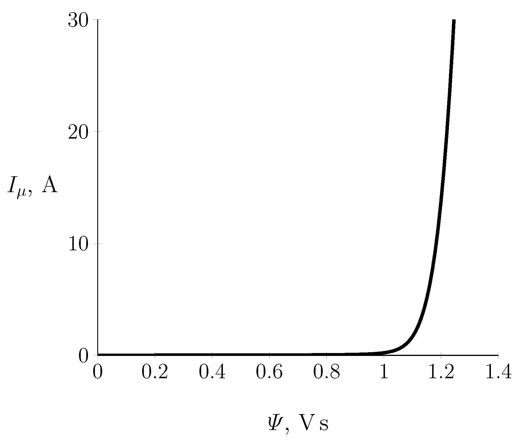
Figure 4 shows a fragment of the non-linear characteristic of the ferromagnetic core of the transformer under test, limited to the value of 30 A and calculated on the basis of the manufacturer’s H ( B ) curve as well as the number of turns and the core geometry.
The polynomial approximation was executed using Formula (10); 11 carefully selected points from H ( B ) curve (Figure 3) were used in the approximation.

2.3. Modeling of the No-Load Steady State Taking into Account the Non-Linear Magnetization Characteristics of the Transformer Core

Achieving steady-state transformer operation with no load requires a relatively long time, especially in relation to the time constants of dynamic events. Therefore, the overall cost of calculating a solution for this device operation (integration of the differential Equations (6) and (7)) is very high.
During the numerical experiment described in [17], it was shown that the result can be achieved without integrating from zero initial conditions. Instead, a solution can be used to find initial conditions that are close to the limit of the solution cycle.
We introduce a linear approximation of the magnetization curves of transformer sheets (a linear approximation of the magnetizing current i μ ( t ) relative to the flux linkage Ψ ( t ) ):
i μ ( t ) = l F e z 1 H ( Ψ ( t ) z 1 s F e ) = def I μ ( Ψ ( t ) ) = l F e Ψ ( t ) μ p z 1 2 s F e = Ψ ( t ) L p
where
L p = z 1 2 R m
in which
R m = l F e μ p s F e
is the magnetic resistance of the magnetic circuit and
μ p = B p H p
is the point on the magnetization curve before its knee.
The system of nonlinear Equations (6) and (7) is transformed into a system of linear equations
d Ψ ˜ ( t ) d t = R F e i ˜ p ( t ) R F e L p Ψ ˜ ( t )
e ( t ) ( L s + L s 1 ) d i ˜ p ( t ) d t + ( R s + R s 1 ) i ˜ p ( t ) + d Ψ ˜ ( t ) d t = 0 .
The system of linear differential equations formulated in such a way already has an analytical solution in the steady state. Using the complex number method, the system of linear differential Equations (16) and (17) is transformed into an algebraic system with the form
( j ω + R F e R m z 1 2 ) Ψ ̲ R F e I ̲ p = 0
E ̲ j ω Ψ ̲ + ( R 1 + j ω L p ) I ̲ p = 0
where
E ̲ = E m e j φ 0
The solution of the system of complex equations is provided by
Ψ ̲ = E ̲ j ω + ( R 1 + j ω L p ) ( R m z 1 2 + j ω 1 R F e ) = Ψ m e j α
I ̲ p = ( R m z 1 2 + j ω 1 R F e ) Ψ ̲ = I p m e j β
The initial conditions sought for the system of nonlinear Equations (6) and (7) take the form
x 1 ( 0 ) = Ψ ( 0 ) = Ψ ˜ ( 0 ) = Im Ψ ̲ x 2 ( 0 ) = i p ( 0 ) = i p ˜ ( 0 ) = Im I ̲ p

3. Stiffness Difficulties in Differential Equations

In Section 2.1 we derive differential Equations (6) and (7), which form the basis for the study of the dynamics of an unloaded transformer. Taking into account the presence of the non-linear relationship I μ ( Ψ ) , these equations may be assigned to the group of rigid problems.
The dilemma of solving stiff problems is constantly addressed in the literature when solving advanced physical problems, mainly the dynamics of events running for a long time [23,24,25,26]. Among the significant troubles accompanying their solution are problems with stability, in particular in the form of false oscillations of the solution ultimately leading to erroneous results (e.g., the trapezoidal method), insufficient accuracy requiring maneuvering the integration step and thus extending the calculation time (e.g., the Euler method), or the relationship between the loss of stability and the increase in the order of the method (e.g., Backward Differentiation Formulae (BDF)/Numerical Differentiation Formulae (NDF) methods) [17].
In the described research, the problem of the stiffness of differential equations surfaces when solving (integrating) Equations (6) and (7) with zero initial conditions. The flux linkage Ψ ( t ) = x 1 ( t ) has a constant component that decays very slowly in subsequent periods of the supply voltage, with simultaneous large changes in the primary current.
The choice of a numerical tool for solving the problem of stiff differential equations imposes requirements on the global stability of the method. Keeping these requirements in mind, the globally stable Runge–Kutta implicit methods appear interesting. Their variants based on Gauss–Legendre, Radau, and Lobatto quadrature approximation [27] allow for obtaining high-order methods. Profound experience in this respect was provided by a numerical experiment [17] consisting of checking (by simulations) which approximation is the best one.
In the current calculations, a high-order variant of the Runge–Kutta implicit method based on Radau IIA quadrature approximation was used. Although the numerical cost of such a method is relatively high, it has a significant advantage with respect to the requirements of large calculation tolerances with a much smaller number of iterations. The selected algorithm is characterized by the presence of an inserted formula that allows the local error of the solution to be tracked. The estimation of the integration error follows the concept of Jacques J.B. de Swart and Gustaf Soderlind [28], where the error vector of the ith iteration is calculated as the difference of the solution X i + 1 and the approximation X ˜ i + 1 ( 1 ) :
E i = E i ( t i + h i , h i ) = X i + 1 X ˜ i + 1 ( 1 )
which, when further developed, takes the form
E i ( t i + h i , h i ) = [ 1 γ h i J ( X i + 1 , t i + h i ) ] 1 [ j = 0 m e j K j ( i ) γ h i F [ X i + 1 , t i + h i ] ]
where J ( X , t ) is the Jacobi matrix of the vector function F ( X , t ) ) .
Details related to the implementation of the method can be found in [17].

4. The Original Method for Calculating the Dynamics and Steady State of an Unloaded Single-Phase Transformer

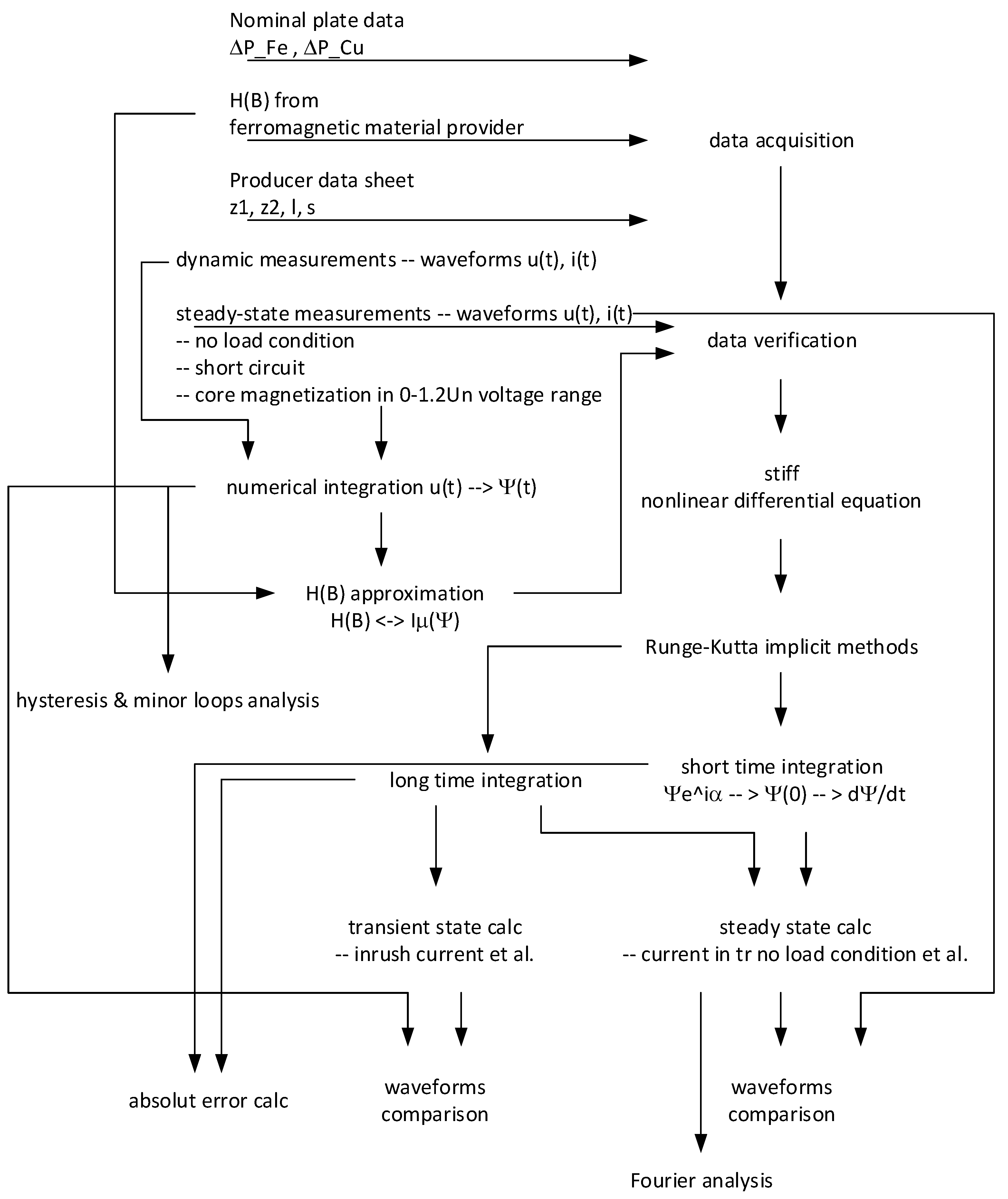
A flowchart (block diagram) of the developed method implementing the described calculations is shown in Figure 5.

5. The Measurements

It was assumed that measurements must be fairly standard, commonly available measuring instruments should be used, and technicians should be able to carry out the tests at industrial sites.
The measurements of the tested transformer were made in two stages, namely, by means of measurements in the steady state with the distinction of AC and DC measurements, then in dynamic states when switching on the unloaded unit. The common feature of the measurements was their form; only voltage and current waveforms were measured and recorded, which was carried out in various configurations. Two signal recorders were used for recording: the Sonel PQM 707 analyzer, commonly used in measurements in industrial conditions (with a sampling frequency of approx 10 kHz) and a professional Kared RZ1 disturbance recorder ( f s = 32 kHz).
In the steady state, the measurements were run in the no-load state and short-circuit state (laboratory facilities).
The longitudinal and transverse parameters of the transformer equivalent diagram (Figure 1) were determined on the basis of the values calculated from the waveforms recorded in the nominal steady states of no-load and short-circuit, respectively. The measurements were made with a sinusoidal alternating current supply. No-load measurements were run over a wide range of supply voltage (0–260 V). For the short-circuit condition, a limit value of 1.1 times the primary rated current of the primary side of the transformer was assumed. Using the waveforms instead of measuring the effective values directly increases the accuracy [29] thanks to the harmonic content and the angular relations between the quantities, as proven by the later harmonic analysis described in Section 6.2. The recording of the waveforms allows the evolution of the so-called ’minor loops’ of the hysteresis to be tracked, permits their analysis along the entire range of the transformer supply voltage [20], and enables verification of the X / R relationship in the phase plane.
The winding resistance values of both sides of the transformer were determined from AC measurements and verified by means of DC measurements. As part of separate measurements, the windings were supplied from a regulated DC power supply with currents corresponding to the effective values of sinusoidal alternating currents resulting from the transformer power. DC methods are most important in measurements, as they serve as a supplement and alternative to AC methods [30].
When estimating X s 1 of the primary side of transformer, the issues presented in the works [31,32,33,34] were taken into account.
The recorded sinusoidal voltage waveforms in the entire available range were used to calculate the flux linked with the primary winding. The estimated pairs of points i 1 Ψ were used to verify a fragment of the magnetization curve and to visualize the evolution of the hysteresis of the tested transformer core. The model reconstruction of the characteristics in the entire range (following the manufacturer’s model) was carried out using polynomial approximation (10).
Transient measurements included the recording of the primary and secondary voltages as well as the current and derivative current of the primary winding. This choice of measured quantities resulted from the specific behavior of the transformer inrush current and the measurement difficulties highlighted in the literature, e.g., resulting from drastic amplitude fluctuations and their changes over time. Basic current measurement was performed using a class 0.1 current transformer together with an event recorder. The basic measurement was supplemented by the recording of the current derivative using a Rogowski coil [35]. Due to the dependence of the transformer inrush current on the initial phase of the supply voltage, a series of dynamic measurements was executed. Each measurement consisted of switching the transformer on and subsequent recording. Numerous results with different phase values were obtained.
The last stage of measurements was a 60-s recording of the process of formation of the steady state in the transformer system from the moment of its activation to the complete disappearance of the constant and aperiodic components.

6. Results of Calculations

All calculations were made with the use of original software written by the authors in C#. This software works with a proprietary solver library containing classes equipped with Runge–Kutta implicit methods designed for integration of systems of differential equations [36,37].
The calculations were based on the measurement-verified data of the single-phase transformer. Nonlinear characteristics of the transformer sheets were used in the calculations. These characteristics were previously positively verified as far as possible. The coefficients of the function H ( B ) obtained from the solution of the estimation problem based on the given points of the magnetization curve of the transformer sheet (Figure 3) are presented in Table 1.
In the calculations, a variant of the implicit Runge–Kutta method based on five-stage approximation of the Radau IIA quadrature, found in [27], was used; this resulted in a ninth-order method. This high order ensures full stability in the integration of rigid equations of types (6) and (7). Calculations were carried out with automatic selection of the integration step, as well as the preset absolute error ϵ a = 1 × 10 7 and relative error ϵ r = 1 × 10 11 .

6.1. Calculation of the Unloaded Transformer Dynamics at the Rated Supply Voltage

First, the dynamics resulting from switching on the voltage were analyzed in accordance with (6) and (7). The following conditions were assumed for the calculations: zero initial conditions, supply voltaged equal to E 1 R M S = 233 V, and an initial phase angle φ 0 = 0 deg, which are consistent with measurement conditions. The integration interval was limited to two periods of the supply voltage. It should be emphasized that among the numerous conducted experiments involving switching on the voltage, the case where the supply voltage passes through zero e ( t ) = E m sin ( ω t + φ 0 ) ; φ 0 = 0 corresponds to the most critical state of transformer operation and to a very high stiffness of the differential equations describing it. For this reason, this variant was intentionally selected for presentation in this paper.
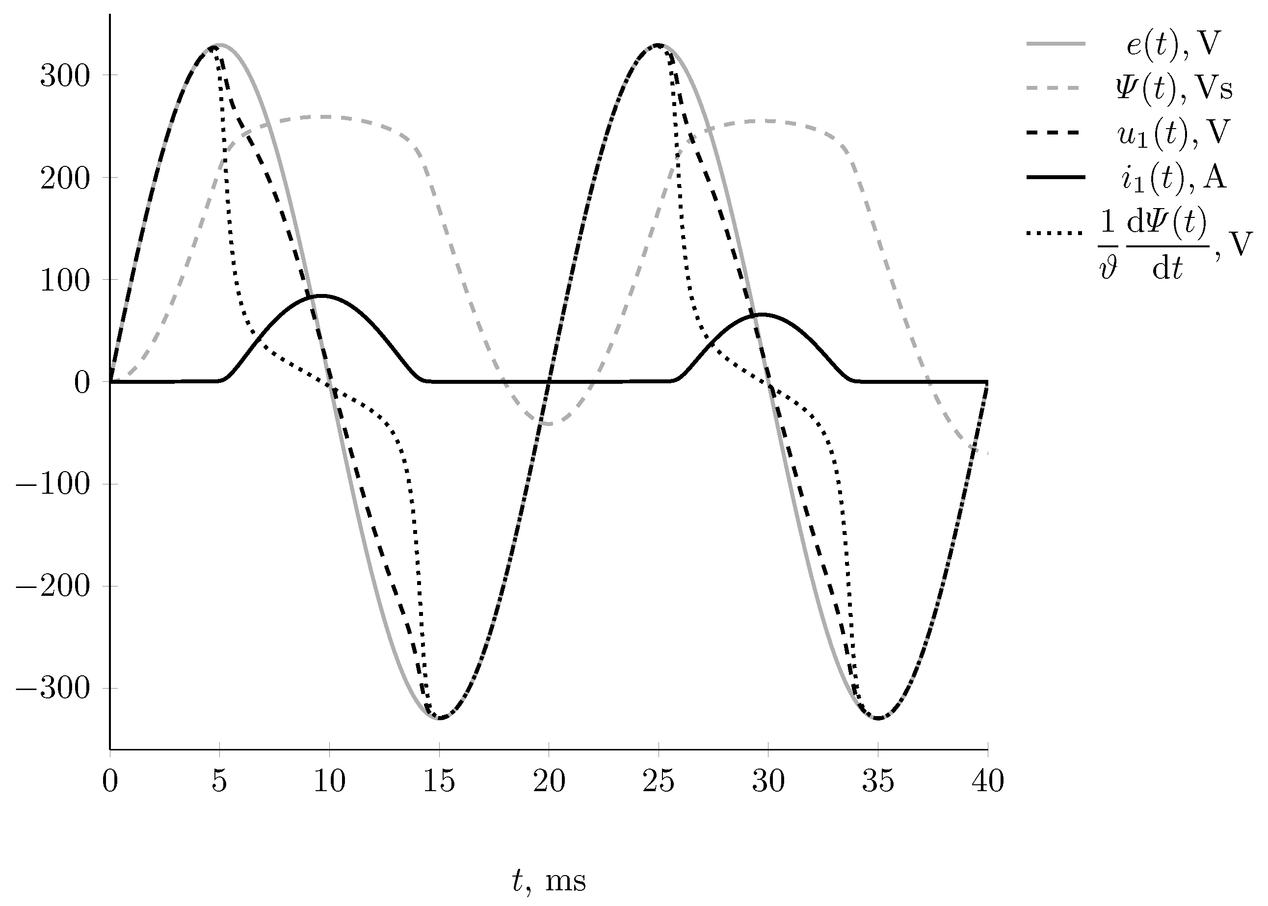
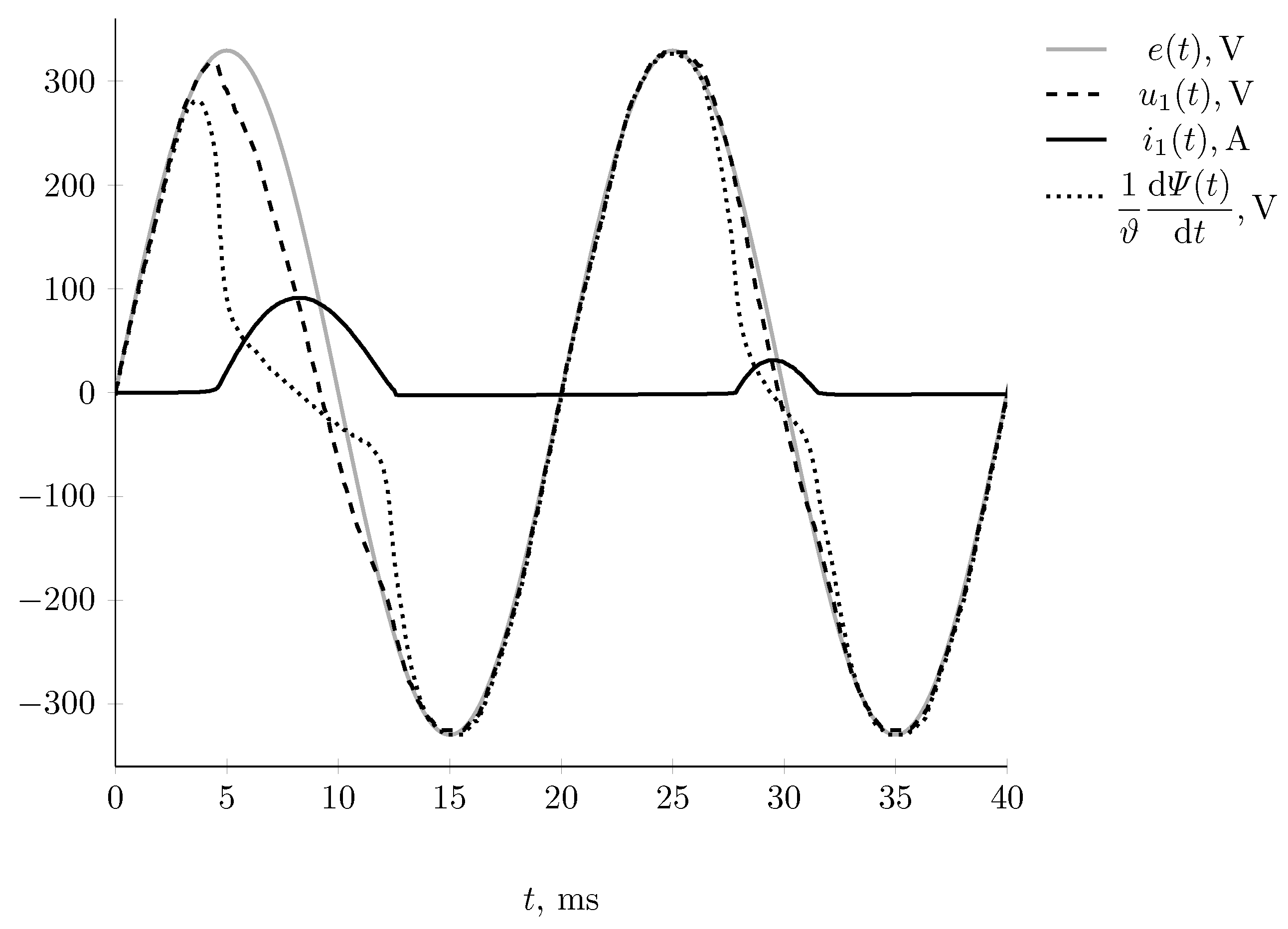
Figure 6 and Figure 7 present the computer simulation results and the recorded measurement waveforms, both showing the complete dynamics of transformer start-up. The visualization covers the waveforms of the state variables Ψ ( t ) and i 1 ( t ) as well as the quantities expressed by their derivatives, i.e., the electromotive force induced in the primary winding d Ψ / d t and the supply voltage at the transformer terminals, which is the supply voltage minus the voltage drop across the impedance of the power source.
The presented waveforms of the transformer electromagnetic quantities, particularly the state variables verified by measurement and simulation, show the genesis and the course of the dynamics of events in the device, notably the inrush current.
Starting with zero initial conditions and zero supply voltage, the magnetic flux Ψ ( t ) linked with the coils z 1 slowly increases with the increase in the supplied voltage e ( t ) . This is accompanied by a slight increase in the current i 1 ( t ) from zero to several hundred milliamperes, although this is not visible for the time range 0–4 ms (Figure 6). However, this current produces a magnetomotive force that generates the flux linkage Ψ ( t ) , the derivative of which is the electromotive force d Ψ / d t induced in the primary coil, slightly different from the supply voltage e ( t ) , meaning that these two waveforms overlap to an extent (Figure 6). After the 4-ms increase in the accompanying flux Ψ ( t ) , the core gradually becomes saturated. With a further increase in the current i 1 ( t ) , there is a slight increase in the flux, which reaches its maximum after a time. The derivative of this flux, i.e., the electromotive force induced in the coil, decreases sharply during this time period, causing the current i 1 ( t ) to rise sharply; it reaches a maximum of about 86 A when the flux Ψ ( t ) passes through its maximum. The current pulse occurring in this time interval produces a very high electromotive force of self-induction across the leakage inductance of the transformer and the equivalent inductance of the power source, which, with a decreasing electromotive force of the coil, d Ψ / d t is equal to the supply voltage. This process is repeated in successive intervals of the supply voltage and disappears after several tens of periods.
The intense rise in the transformer supply current continues until the secondary side voltage u 2 ( t ) passes through zero, when the current reaches its maximum. The maximum of the considered current impulse (waveforms obtained from the model) is close to the recorded value of 90 A (measured waveforms), and is over ten times greater than the rated current value.
The conducted experiment confirmed our assumptions that the size of the inrush current pulse is strongly influenced by the internal impedance of the power source. It should be noted that after a few milliseconds from the switch-on time instance, the voltage at the transformer terminals u 1 ( t ) is lower than the supply voltage by the value of the voltage drop across the internal impedance of the power source (Figure 6 and Figure 7).
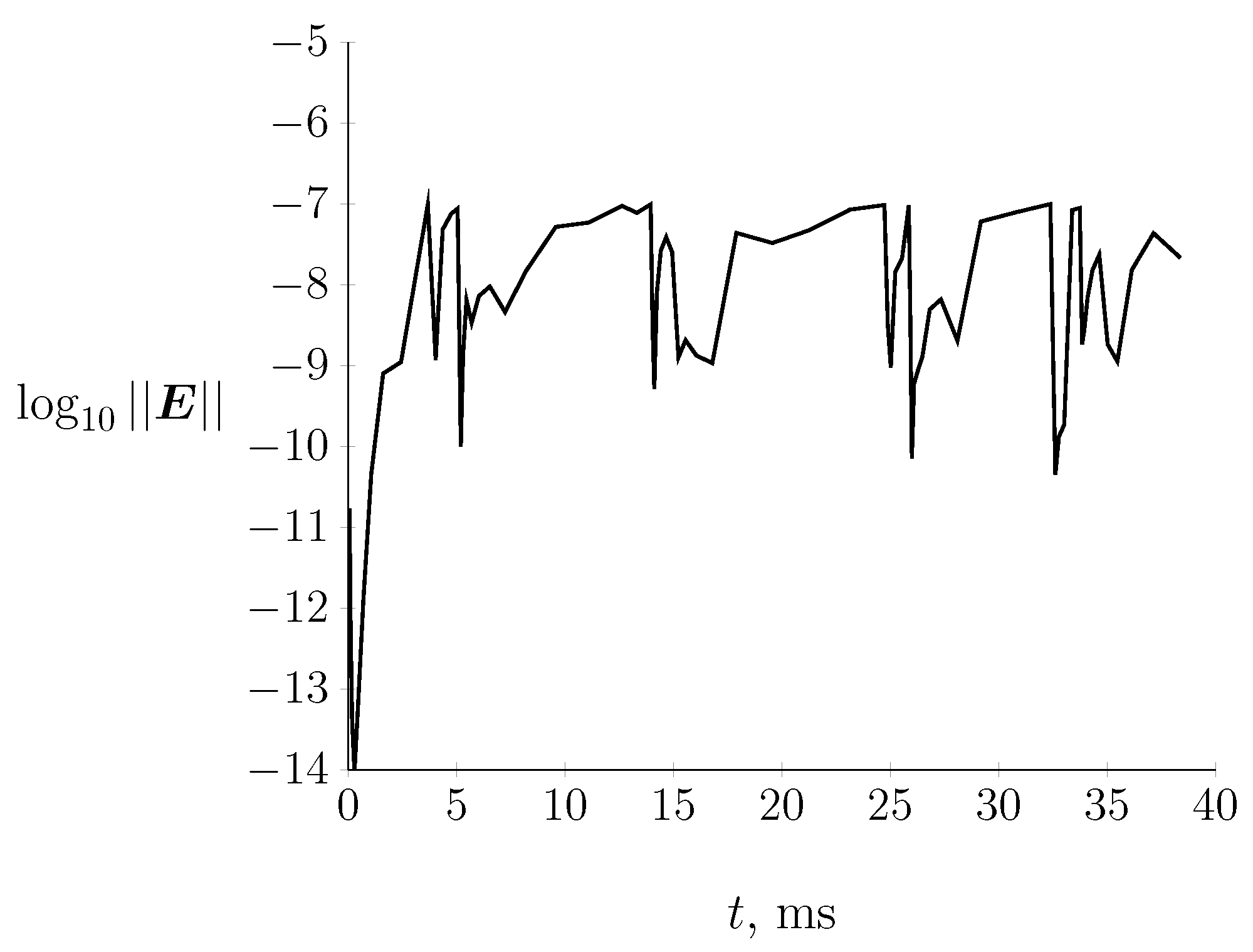
Figure 8 shows the decimal logarithm of the norm of the error vector estimated in the computation process for the case shown in Figure 6.
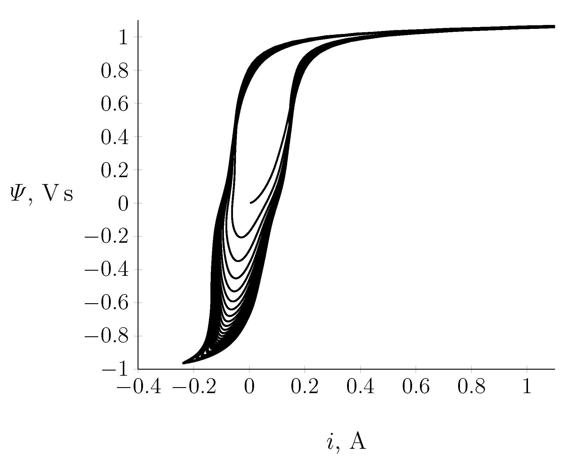
Figure 9 shows the phase plane of the state variables Ψ ( i 1 ) for the first fifteen integration periods of the system of differential Equations (6) and (7). In each integration period there is a time interval in which the state variable Ψ ( t ) changes slightly with large changes in i 1 ( t ) . In contrast, at small currents i 1 ( t ) , the flux linkage Ψ ( t ) changes rapidly.
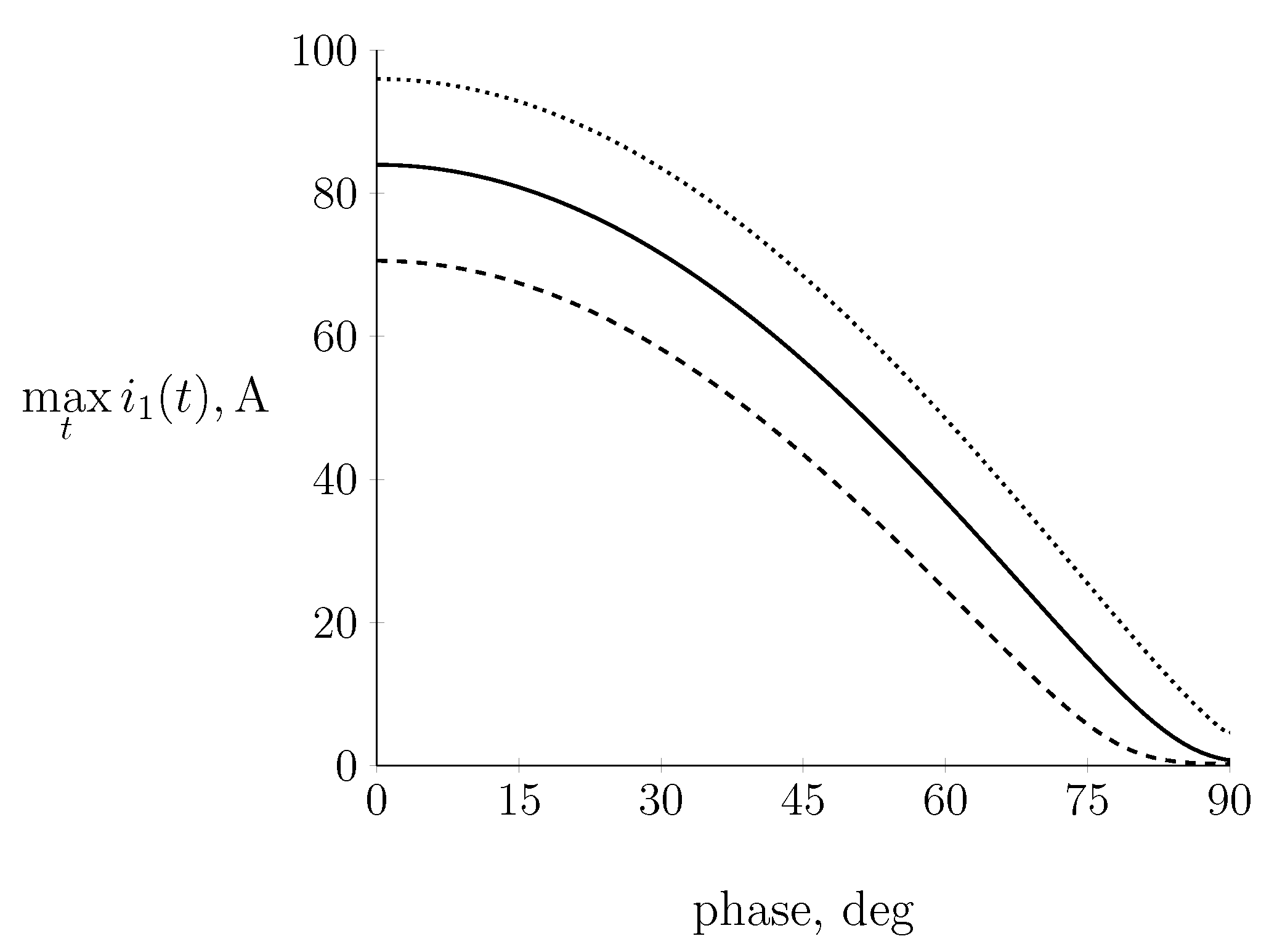
The stiffness of the system of differential Equations (6) and (7) is proven by the magnitudes of the current pulses in the primary current waveform i 1 ( t ) (Figure 6 and Figure 7). They depend on the initial phase φ 0 of the supply voltage e ( t ) = E m sin ( ω t + φ 0 ) and reach their maximum values for the zero initial phase φ 0 = 0 , which corresponds to the zero initial value of the supply voltage e ( 0 ) = 0 . To confirm this, the research was extended to numerical experiments in which two additional taps were established for the tested transformer with 280 and 344 turns, respectively. It is clear from Figure 10 that a greater voltage per turn in the transformer leads to greater magnitude of the current pulses. The value of this quantity determines the saturation point to which the transformer operating point may extend. This is equivalent to stating that higher magnetic saturation of the transformer core leads to larger current pulses occurring when the transformer is turned on.

6.2. Calculation of the Steady State of the Transformer Resulting from Switching on the Rated Supply Voltage

In the studies of the transient state of the transformer, in all calculation cases, and especially for large integration time intervals, the algorithm maintained a given absolute error in the calculation of state variables. The steady state can therefore be achieved by integrating the differential Equations (6) and (7) within a few seconds. However, this can be achieved initially as well, as shown in Section 2.3.
For the linear approximation of the system of Equations (16) and (17), the steady-state solution (21) and (22) at the sinusoidal voltage excitation e ( t ) = E m sin ( ω t + φ 0 ) with a complex value of E = E m e j φ 0 can be expressed as follows:
Ψ ˜ ( t ) = Im Ψ ̲ e j ω t = Ψ m sin ( ω t + α ) i ˜ p ( t ) = Im i ̲ p e j ω t = I p m sin ( ω t + β )
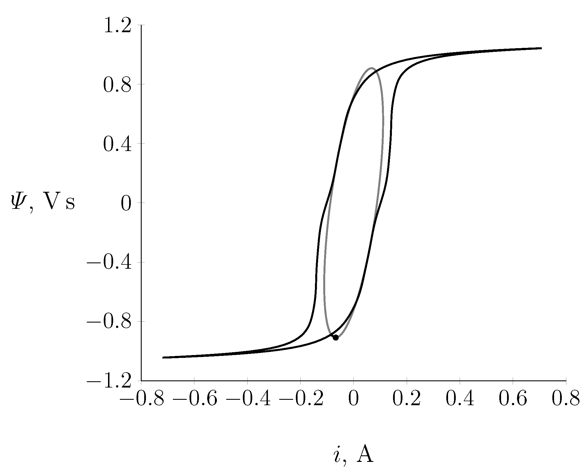
Because the phases of the current i ˜ 1 ( t ) and the flux linkage Ψ ˜ ( t ) in the steady state are generally different ( α β ), these quantities may be represented by an ellipse in the range of one period on the phase plane. As the non-linearity of the magnetization curve does not significantly affect transformer’s operating state, we may expect the limit cycle for the non-linear transformer model to introduce a certain deformation of this ellipse. This results in an oval shape that is symmetrical with respect to the zero point of the coordinate system (plane phase system). By selecting the initial condition of integration (23) for the system of Equations (6) and (7) from the solution of the linear approximation of the system (16) and (17), it is enough to carry out the computational process in the range of two periods to achieve a steady state, which on the phase plane is the limit cycle shown in Figure 11. The same figure shows the steady state limit cycle for the linear model of the transformer. The initial condition (23) is a point on this limit cycle.
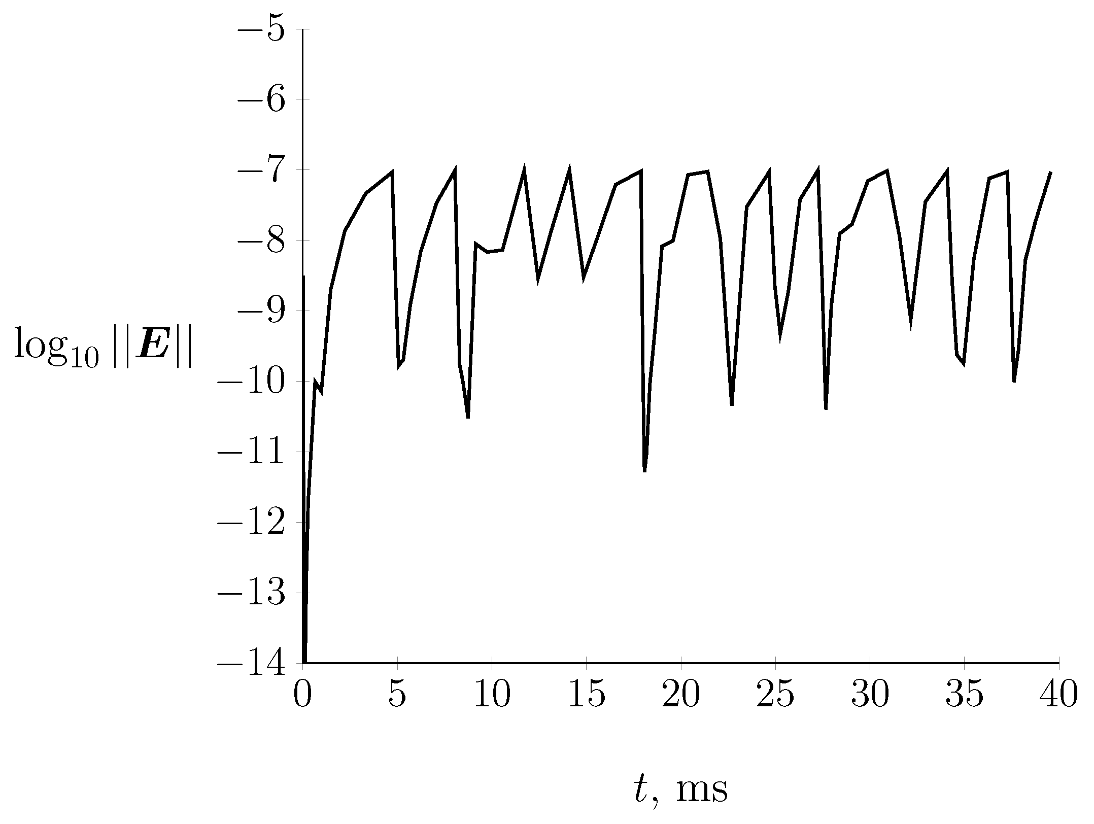
Figure 12 shows the course of changes in the absolute error value in the process of integration of the system of Equations (6) and (7) from the solution of the linear approximation of the system (16) and (17). The integration process was carried out consistently by means of the five-step method of Radau IIA with automatic selection of the integration step at the given identical absolute error ϵ a = 1 × 10 7 and relative error ϵ r = 1 × 10 11 .
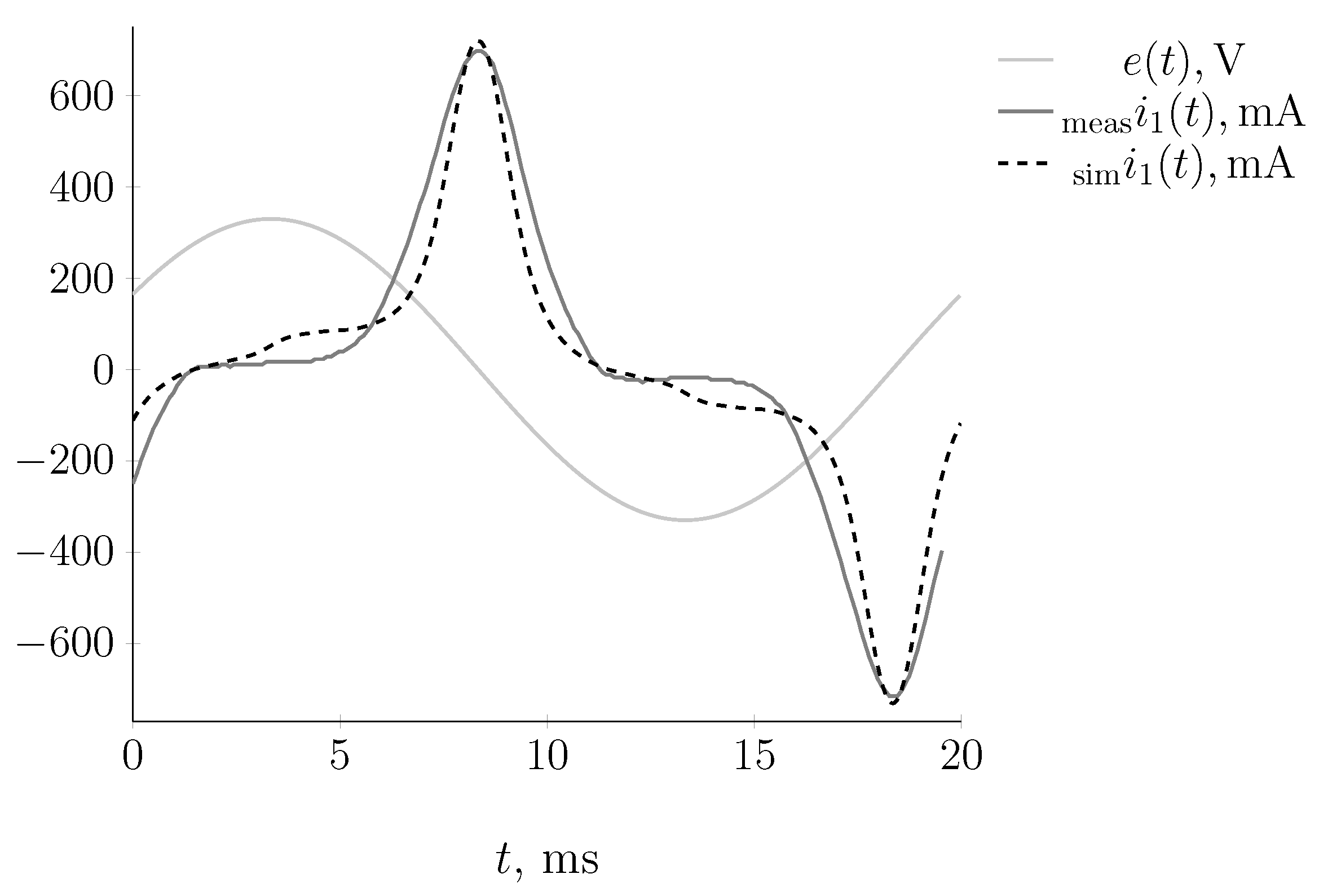
In Figure 13, the measured and simulated waveforms of the steady-state current of the transformer primary side at the rated no-load conditions are summarized.
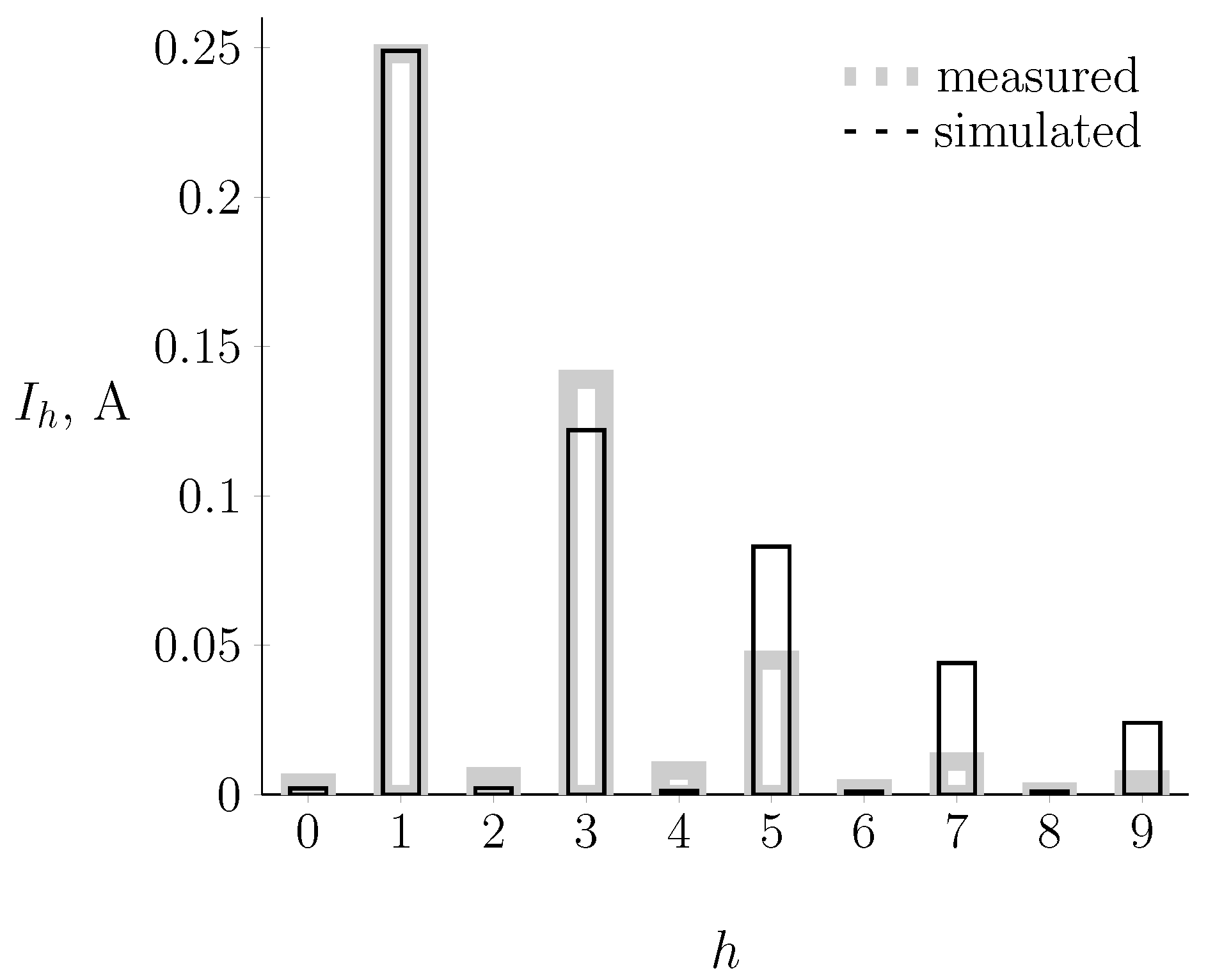
The algorithm for determining the steady state of the transformer while taking into account its non-linearity can be used to determine the rated operating point on the magnetization curve of transformer sheets from the point of view of the content of higher harmonics in the no-load current. For this purpose, the method allows integration to be performed in the interval of one period with a constant integration step; this makes it possible to execute a discrete Fourier transform [38,39]. Thus, it is possible to determine the higher harmonics in the no-load current in the steady state for the non-linear transformer model, depending on the operating point on the non-linear magnetization curve. For example, for the calculations shown in Figure 13 as a final stable result of Figure 11, the content of higher harmonics in the no-load current is provided in Figure 14 and compiled for comparison purposes with the measurement results in Table 2.
Judging from the bar plot depicting the difference between the computed and measurement harmonics, the difference can mainly be noticed for higher harmonics, while the fundamental harmonic has close resemblance with very good accuracy.

7. Conclusions

The methodology presented in this paper led to several results, which may be summarized as follows:
-
The applied variant of the Runge–Kutta implicit method based on high-order Radau IIA quadrature approximation can be successfully used to solve stiff problems in the analysis of the dynamics of an unloaded transformer.
-
The proposed model described by stiff nonlinear ordinary differential equations offers high accuracy of the obtained results and is an effective tool for comprehensive analysis of transformer operation.
-
Our calculation results are correct, as verified by measurements; this proves the effectiveness of the selected (five-stage variant of the implicit Runge–Kutta method based on the Council’s IIA quadrature approximation method of the 9th order). The correctness of selecting this method is additionally confirmed by the analysis of the behavior of the state variables Ψ ( i 1 ) in subsequent integration periods of the systems of differential equations. The time functions of these quantities create attractors in the phase plane.
-
In each integration period, there is a time interval in which the state variable Ψ ( t ) changes slightly with large changes of i 1 ( t ) , or inversely, where small changes in the current i 1 ( t ) are accompanied by rapid changes in the flux linkage Ψ ( t ) . This shows how stiff the problem is and how important it is to use the globally stable IIA Council algorithm to integrate the system of nonlinear differential Equations (6) and (7).
-
The stiffness of the system of differential Equations (6) and (7) is proven by the magnitudes of the current pulses in the primary current waveform i 1 ( t ) . The magnitudes of these current pulses depend on the initial phase φ 0 of the supply voltage, and reach their maximum values for its zero value.
-
Greater magnitudes of the current pulses are connected to higher per-turn voltages in the transformer. Thus, it can be concluded that higher magnetic saturation of the transformer core leads to larger current pulses occurring when the transformer is switched on. This is an important guideline for the transformer design process.
-
The maximum current pulse recorded by measurement coincides with the value reproduced by the model, and is more than ten times greater than the rated current value. The conducted experiment confirmed that the internal impedance of the power source has a large influence on the current impulse size.
-
The steady state can be achieved computationally by selecting the initial integration condition for the system of nonlinear differential Equations (6) and (7) from the solution of the linear approximation of the system (16) and (17) in the form (23). In this way, the result (reaching the steady state) can be obtained within two periods.
-
The analysis of the error courses shown in Figure 8 and Figure 12 proves the correctness of selecting the algorithm of the five-stage Radau IIA method with automatic selection of the integration step for investigating the transient state of the transformer. In all the calculations, and especially for large integration time intervals, the algorithm maintained the given absolute error.
-
The algorithm used to determine the steady state of the transformer while taking into account its nonlinearity can be used to determine the higher harmonics in the no-load current depending on the operating point on the non-linear magnetization curve.
-
In comparing the results of our numerical calculations with the measurement results shown in Table 2, a slight difference in the harmonic values can be noted; this proves that the approximate model of the transformer is effective in describing both transient and steady states.
-
The implementation of the integration process for long time intervals for the purpose of calculating the steady state of the transformer is feasible, despite the stiffness of the differential Equations (6) and (7), thanks to the absolute stability of the implicit method used in the calculation process.
-
The good resemblance of the measurements obtained through the simulated waveforms is apparent. Eventually, further improvements can be considered through extensions of the model, e.g., the introduction of fractional calculus, as proposed in [20,40] for ferromagnetic core coils.

Author Contributions

Conceptualization, Ł.M. and P.Z.; methodology, Ł.M. and B.B.; software, Ł.M. and B.B.; validation, Ł.M., B.B. and P.Z.; formal analysis, Ł.M. and P.Z.; investigation, Ł.M.; resources, Ł.M. and P.Z.; data curation, P.Z.; writing—original draft preparation, Ł.M.; writing—review and editing, Ł.M., B.B. and P.Z.; visualization, Ł.M. and P.Z.; supervision, P.Z. All authors have read and agreed to the published version of the manuscript.

Funding

The presented work was financed by a subsidy of the Polish Ministry of Education and Science for AGH University of Science and Technology in Krakow.

Data Availability Statement

Not applicable.

Acknowledgments

This paper is a result of the scientific internship accomplished by Łukasz Majka at the AGH University of Science and Technology.

Conflicts of Interest

The authors declare no conflict of interest.

Appendix A

Table A1. Nomenclature.
u 1 voltage at the terminals of the primary side of the transformer
u 2 voltage at the terminals of the secondary side of the transformer
ϑ turns ratio of the transformer
Ψ flux linkage associated with the transformer’s primary coil, computed as Ψ ( t ) = z 1 Φ ( t )
i 1 transformer primary current
R F e equivalent resistance representing the iron core losses
i F e active component of the transformer’s idle current
i μ reactive component of the transformer’s no-load current
R s equivalent resistance of the power grid (power source)
L s equivalent inductance (reactance) of the power grid (power source)
R s 1 primary winding resistance
L s 1 leakage inductance of the primary winding
Hmagnetic field strength
Φ main flux leakage (effective value of the flux)
Bmagnetic induction
s F e cross-sectional area of the core of the transformer
l F e mean path length of the core
μ 0 permeability of free space
δ length of the equivalent air gap
z 1 number of turns in the primary windings
μ F e permeability of the ferromagnetic substance
esinusoidal supply voltage
φ 0 phase of the initial supplied voltage
ω pulse
Table A2. Manufacturing data of the modeled Breve TUM 1600/A 230/400V transformer.
Quantity, UnitValue
Transformer nominal supply voltage, V230
Rated secondary side voltage, V400
Rated primary current, A6.95
Power loss in iron, W16.75
Power loss in copper, W42.58
No-load primary side current, A0.286
Short-circuit voltage, V47.97
Core cross-sections, m 2 0.002025
Column length, m0.175
Length of the yoke, m0.085
Number of primary winding turns, N310
Equivalent resistance of the network, Ω 0.1
Equivalent reactance of the network, Ω 0.5

References

  1. Harlow, J.H. Electric Power Transformer Engineering, 3rd ed.; Taylor & Francis Group, LLC: Boca Raton, FL, USA, 2013. [Google Scholar]
  2. Altun, H.; Sünter, S.; Aydoğmuş, Ö. Modeling and analysis of a single-phase core-type transformer under inrush current and nonlinear load conditions. Electr. Eng. 2021, 103, 2961–2972. [Google Scholar] [CrossRef]
  3. Seo, H.-C.; Gwon, G.-H. Systematization of the Simulation Process of Transformer Inrush Current Using EMTP. Appl. Sci. 2019, 9, 2398. [Google Scholar] [CrossRef] [Green Version]
  4. Xie, J.; Elizondo, M.A.; Tuffner, F.K.; Schneider, K.P. Dynamic-Phasor Model of Transformer Inrush Simulation for Unbalanced Distribution System. In Proceedings of the 2020 IEEE/PES Transmission and Distribution Conference and Exposition (T&D 2020), Chicago, IL, USA, 12–15 October 2020; pp. 1–5. [Google Scholar]
  5. Barros, R.M.; da Costa, E.G.; Araujo, J.F.; de Andrade, F.L.; Ferreira, T.V. Contribution of inrush current to mechanical failure of power transformers windings. High Volt. 2019, 4, 300–307. [Google Scholar] [CrossRef]
  6. Mikhak-Beyranvand, M.; Rezaeealam, B.; Faiz, J.; Rezaei-Zare, A. Impacts of ferroresonance and inrush current forces on transformer windings. Electr. Power Appl. 2019, 13, 914–921. [Google Scholar] [CrossRef]
  7. Department of Public Service. Investigation by the City of New York into the Northwest Queens July 2006 Power Outages; Department of Public Service: Montpelier, VT, USA, 2007. Available online: http://www.dps.ny.gov/06E0894/06E0894_NYCity_Report.pdf (accessed on 19 June 2022).
  8. Ge, W.; Zhang, C.; Xie, Y.; Yu, M.; Wang, Y. Analysis of the Electromechanical Characteristics of Power Transformer under Different Residual Fluxes. Energies 2021, 14, 8244. [Google Scholar] [CrossRef]
  9. Gunda, S.K.; Dhanikonda, V.S.S.S.S. Discrimination of Transformer Inrush Currents and Internal Fault Currents Using Extended Kalman Filter Algorithm (EKF). Energies 2021, 14, 6020. [Google Scholar] [CrossRef]
  10. Mitra, J.; Xu, X.; Benidris, M. Reduction of Three-Phase Transformer Inrush Currents Using Controlled Switching. IEEE Trans. Ind. Appl. 2020, 56, 890–897. [Google Scholar] [CrossRef]
  11. Komarzyniec, G. Calculating the Inrush Current of Superconducting Transformers. Energies 2021, 14, 6714. [Google Scholar] [CrossRef]
  12. Yadav, S.; Suman, G.K.; Mehta, R.K. Study of Electromagnetic Forces on Windings of High Voltage Transformer during Short Circuit Fault. In Proceedings of the 2020 3rd International Conference on Energy, Power and Environment: Towards Clean Energy Technologies, Shillong, India, 5–7 March 2021; pp. 1–5. [Google Scholar]
  13. Lin, X.; Liu, J.; Wang, F.; Ai, W.; Li, Z.; Chen, S. Magnetic-Structural Coupled Simulation of Power Transformer Winding Cumulative Effect. In Proceedings of the 2022 IEEE 5th International Electrical and Energy Conference (CIEEC), Nanjing, China, 27–29 May 2022; pp. 2860–2865. [Google Scholar]
  14. Majka, Ł. Fractional derivative approach in modeling of a nonlinear coil for ferroresonance analyses. In Non-Integer Order Calculus and Its Applications. RRNR 2017. Lecture Notes in Electrical Engineering; Ostalczyk, P., Sankowski, D., Nowakowski, J., Eds.; Springer: Cham, Switzerland, 2019; Volume 496, pp. 135–147. [Google Scholar]
  15. Furgał, J.; Kuniewski, M.; Pajak, P. Analysis of Internal Overvoltages in Transformer Windings during Transients in Electrical Networks. Energies 2020, 13, 2644. [Google Scholar] [CrossRef]
  16. Garda, B. Improved quasi-Newton algorithm for the optimal coil design problem. In Proceedings of the Progress in Applied Electrical Engineering (PAEE), Koscielisko, Poland, 17–21 June 2019; pp. 1–4. [Google Scholar]
  17. Baron, B.; Kolańska-Płuska, J.; Waindok, A.; Kraszewski, T.; Kawala-Sterniuk, A. Application of Runge-Kutta implicit methods for solving stiff non-linear differential equations of a single-phase transformer model in the no-load state. In Proceedings of the 37th International Business Information Management Association Conference (IBIMA), Cordoba, Spain, 30–31 May 2021; pp. 8071–8087. [Google Scholar]
  18. Dekker, K.; Verwer, J.G. Stability of Runge-Kutta Methods for Stiff Nonlinear Differential Equations; Elsevier Science Publishers B.V.: Amsterdam, The Netherlands; New York, NY, USA; North-Holland: Amsterdam, The Netherlands, 1984. [Google Scholar]
  19. Ayachit, A.; Kazimierczuk, M.K. Steinmetz Equation for Gapped Magnetic Cores. IEEE Magn. Lett. 2016, 7, 1–4. [Google Scholar] [CrossRef]
  20. Sowa, M.; Majka, Ł. Ferromagnetic core coil hysteresis modeling using fractional derivatives. Nonlinear Dyn. 2020, 101, 775–793. [Google Scholar] [CrossRef]
  21. Stalprodukt. Transformer Plates and Cores. Available online: https://www.stalprodukt.com.pl/pub/File/PDF/blachy_i_rdzenie/blachy_i_rdzenie.pdf (accessed on 29 March 2022).
  22. Delfour, M.C.; Dubeau, F. Discontinuous Polynomial Approximations in the Theory of One-Step, Hybrid and Multistep Methods for Nonlinear Ordinary Differential Equations. Math. Comput. 1986, 47, 169–189. [Google Scholar] [CrossRef]
  23. Yang, R.; Yang, Y.; Xing, Y. High order sign-preserving and well-balanced exponential Runge-Kutta discontinuous Galerkin methods for the shallow water equations with friction. J. Comput. Phys. 2021, 444, 110543. [Google Scholar] [CrossRef]
  24. Herrera, L.; Di Prisco, A.; Ospino, J. Hyperbolically Symmetric Versions of Lemaitre–Tolman–Bondi Spacetimes. Entropy 2021, 23, 1219. [Google Scholar] [CrossRef]
  25. Pisarski, R.D. Remarks on nuclear matter: How an ω0 condensate can spike the speed of sound, and a model of Z(3) baryons. Phys. Rev. D 2021, 103, L071504. [Google Scholar] [CrossRef]
  26. Astashenok, A.V.; Capozziello, S.; Odintsov, S.D.; Oikonomou, V.K. Novel Stellar Astrophysics from Extended Gravity. Europhys. Lett. 2021, 134, 59001. [Google Scholar] [CrossRef]
  27. Calvo, M.; Montijano, J.; Gonzalez-Pinto, S. On the existence of solution of stage equations in implicit Runge–Kutta methods. J. Comput. Appl. Math. 1999, 111, 25–36. [Google Scholar] [CrossRef] [Green Version]
  28. de Swart, J.J.B.; Sőderlind, G. On the construction of error estimators for implicit Runge-Kutta methods. J. Comput. Appl. Math. 1997, 86, 347–358. [Google Scholar] [CrossRef] [Green Version]
  29. Dirik, H.; Gezegin, C.; Özdemir, M. A Novel Parameter Identification Method for Single-Phase Transformers by Using Real-Time Data. IEEE Trans. Power Deliv. 2014, 29, 1074–1082. [Google Scholar] [CrossRef]
  30. Majka, Ł.; Szuster, D. Application of the stationary DC decay test to industrial turbogenerator model parameter estimation. Prz. Elektrotechniczny 2014, 90, 242–245. [Google Scholar]
  31. Chiesa, N.; Mork, B.A.; Høidalen, H.K. Transformer Model for Inrush Current Calculations: Simulations, Measurements and Sensitivity Analysis. IEEE Trans. Power Deliv. 2010, 25, 2599–2608. [Google Scholar] [CrossRef]
  32. de Leon, F.; Semlyen, A. Complete transformer model for electromagnetic transients. IEEE Trans. Power Deliv. 1994, 9, 231–239. [Google Scholar] [CrossRef] [Green Version]
  33. Hempstead, C.F.; Kressler, D.R.; Avery, R.W.; Banzi, F.J.; Carniglia, B.D.; Olsen, A.; Sternstrom, K.W.; Walker, R.C. Chapter 13—Magnetic-Core Transformers and Reactors. In Reference Data for Engineers, 9th ed.; Middleton, W.M., Van Valkenburg Mac, E., Eds.; Elsevier Inc.: Amsterdam, The Netherlands, 2002; pp. 13-1–13-29. [Google Scholar]
  34. Ćalasan, M.P.; Jovanović, A.; Rubežić, V.; Mujičić, D.; Deriszadeh, A. Notes on Parameter Estimation for Single-Phase Transformer. IEEE Trans. Ind. Appl. 2020, 56, 3710–3718. [Google Scholar] [CrossRef]
  35. Piekielny, P.; Waindok, A. Using a Current Shunt for the Purpose of High-Current Pulse Measurement. Sensors 2021, 21, 1835. [Google Scholar] [CrossRef]
  36. Hairer, E.; Wanner, G. Solving Ordinary Differential Equations II: Stiff and Differential-Algebraic Problems, 2nd ed.; Springer: Berlin/Heidelberg, Germany, 2010. [Google Scholar]
  37. Dos Passos, W. Numerical Methods, Algorithms and Tools in C#; CRC Press: Boca Raton, FL, USA, 2016. [Google Scholar]
  38. Zydron, P.; Kuniewski, M.; Fuśnik, Ł. Time-Frequency Analysis of Excitation Signals Used to Determine the Transfer Function of the Power Transformers Windings. In Proceedings of the Progress in Applied Electrical Engineering (PAEE), Koscielisko, Poland, 17–21 June 2019; pp. 1–4. [Google Scholar]
  39. Gao, K.; Xie, R.; Zhang, G. Harmonic Analysis of Nonlinear Periodic Network Using the Dynamic Harmonic Domain. In Proceedings of the 7th International Forum on Electrical Engineering and Automation (IFEEA), Hefei, China, 25–27 September 2020; pp. 616–622. [Google Scholar]
  40. Sowa, M. Ferromagnetic coil frequency response and dynamics modeling with fractional elements. Electr. Eng. 2021, 103, 1737–1752. [Google Scholar] [CrossRef]
Figure 1. Equivalent diagram of a single-phase transformer.
Energies 15 07651 g001
Figure 2. Scheme of the considered single-phase transformer.
Energies 15 07651 g002
Figure 3. Manufacturer’s magnetization characteristic of the test transformer sheets.
Energies 15 07651 g003
Figure 4. I μ ( Ψ ) curve calculated on the basis of manufacturer’s data ( H ( B ) curve), number of turns, and core geometry).
Energies 15 07651 g004
Figure 5. Diagram of the methodology.
Energies 15 07651 g005
Figure 6. Waveforms of the state variables Ψ ( t ) , i 1 ( t ) obtained from the model along with the quantities expressed by their derivatives, i.e., the electromotive force induced in the secondary winding d Ψ / d t and the supply voltages e ( t ) and u 1 ( t ) at the transformer terminals. The scale of the y-axis is common for the current (A), voltages (V), and flux (Vs).
Energies 15 07651 g006
Figure 7. Measurement waveforms of the instantaneous voltages and currents recorded when the supply voltage crosses zero ( φ 0 = 0 ). The scale of the y-axis is common for the current (A) and voltages (V).
Energies 15 07651 g007
Figure 8. The decimal logarithm of the norm of the error vector estimated in the calculation process according to Formula (25) for the case shown in Figure 6.
Energies 15 07651 g008
Figure 9. Phase plane Ψ ( i 1 ) of the state variables for fifteen integration periods of Equations (6) and (7).
Energies 15 07651 g009
Figure 10. Maximum values of current pulses m a x | i 1 ( t ) | (simulated values) on the primary side of the transformer depending on the initial phase of the supply voltage; dashed line in the experiment with a reduced number of turns (280), dotted line for the case of increasing the number of turns up to 344, computed example (310 turns, Appendix A, Table A2) as a solid line.
Energies 15 07651 g010
Figure 11. Steady-state phase plane for linear and nonlinear model. The point located on the curve indicates the limit cycle between the linear and nonlinear parts of the solution.
Energies 15 07651 g011
Figure 12. The decimal logarithm of the norm of the error vector estimated during the calculation process for the solution shown in Figure 11.
Energies 15 07651 g012
Figure 13. Voltage and current records (measured and simulated) for the steady-state operation of the unloaded transformer. The current is expressed in mA, and the scale of the y-axis is common for the current (mA) and voltage (V).
Energies 15 07651 g013
Figure 14. Summary of the harmonic content in the transformer no-load current at 233V supplied voltage for measured and simulated waveforms.
Energies 15 07651 g014
Table 1. Function H ( B ) coefficients obtained from solving the estimation problem based on the manufacturer’s data.
i a i
154.6566
2−176.5693
3579.0243
4−1154.8992
51417.3425
6−1092.5563
7529.4832
8−157.1268
926.7964
10−2.3092
110.0777
Table 2. Harmonic content of the steady-state current of the unloaded transformer from measurements and simulations.
I 1 R M S , A I 1 h , A I 3 h , A I 5 h , A
simulated0.2920.2480.1210.083
measured0.2900.2490.1400.045
Publisher’s Note: MDPI stays neutral with regard to jurisdictional claims in published maps and institutional affiliations.