
An Integrated Lightning Risk Assessment of Outdoor Air-Insulated HV Substations


Abstract
:1. Introduction
2. Literature Review
2.1. Tolerable Risk Values
2.2. Lightning Strike Distance (S)
2.2.1. Basic Impulse Level (BIL)
2.2.2. Lightning Stroke Current (I)
2.3. Lightning Flash Density
3. Methodology
3.1. Risk Components
3.2. Collection Areas
3.3. Case Studies
4. Results and Discussions
4.1. Risk Factor Characteristics
4.1.1. Common Values of Risk Factors
4.1.2. Significant Range of Risk Factors
4.1.3. Ambiguity of Risk Criteria
4.1.4. Ambiguity of Risk Values
4.1.5. Ambiguity Level of Risk Factors
4.1.6. Comparison of Ambiguous Factors to Actual Cases
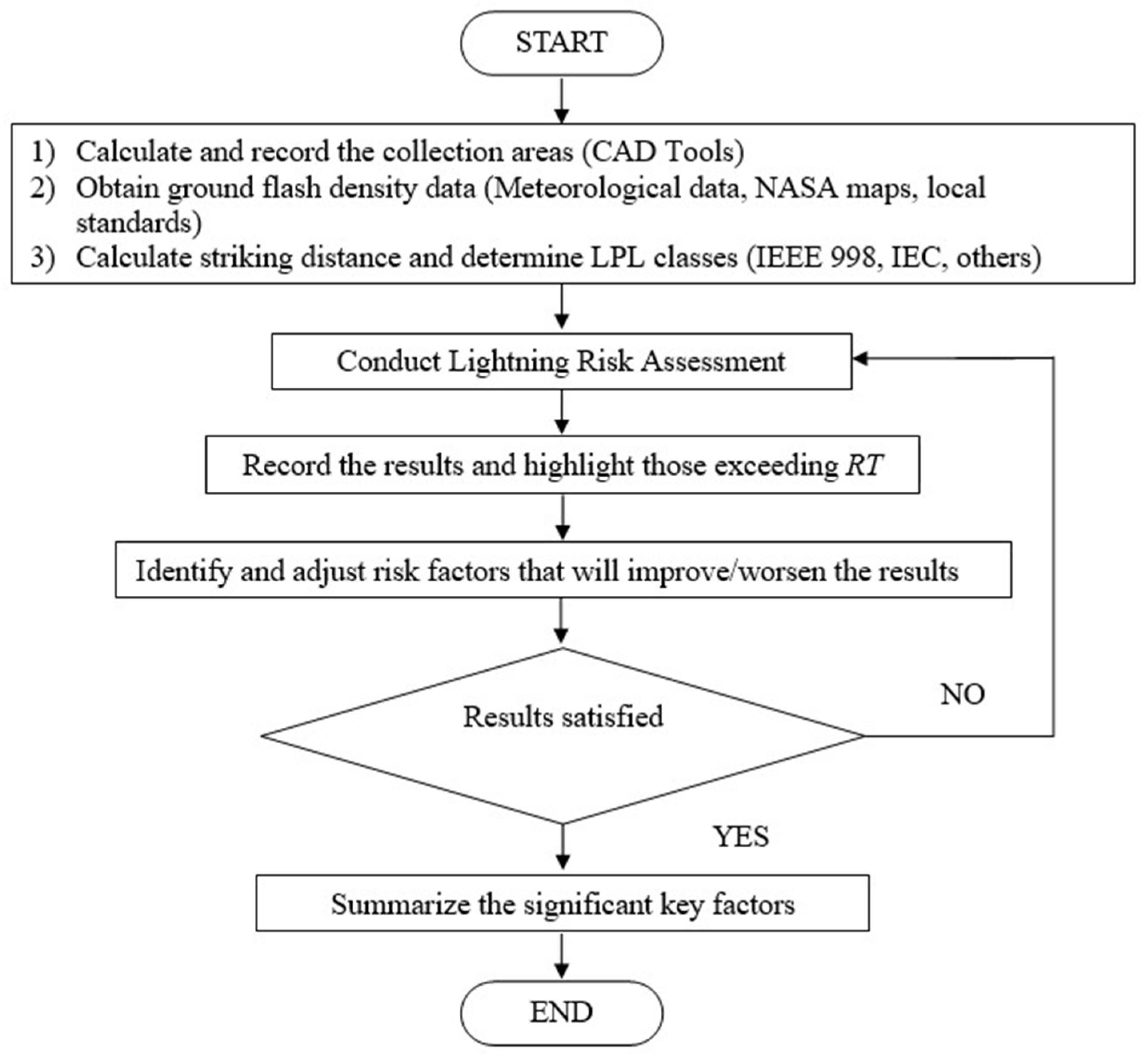
4.2. Integrated Process of Lightning Risk Assessment
Iterations of Lightning Risk Assessment
5. Conclusions
Author Contributions
Funding
Institutional Review Board Statement
Informed Consent Statement
Data Availability Statement
Acknowledgments
Conflicts of Interest
References
- Wagner, C.F.; McCann, G.D.; Lear, C.M. Shielding of substations. IEEE Electr. Eng. 1942, 61, 96–99. [Google Scholar] [CrossRef]
- Lusby, J.R. Fundamental Concepts in Substation Design. In Rural Electric Power Conference; IEEE: New York, NY, USA, 1993. [Google Scholar]
- IEEE 998; Guide for Direct Lightning Stroke Shielding of Substations. IEEE: New York, NY, USA, 2012.
- Gamble, R.D.; Laughner, T. Lightning Studies to Improve Power Quality. In Proceedings of the 24th International Lightning Detection Conference & 6th International Lightning Meteorology Conference, San Diego, CA, USA, 18–21 April 2016. [Google Scholar]
- Meliopoulos, A.S.; Cokkinides, G.J. Substation Lightning Shielding and Risk Assessment. ETEP 2003, 13, 407–412. [Google Scholar] [CrossRef]
- Cruz, F.A.; Sarramegna, S.; Taine, W.S. Lightning Risk Evaluation-Field Experience. In Proceedings of the ICLP 33rd Conference, Estoril, Portugal, 25–30 September 2016. [Google Scholar]
- Abulaban, H.; Siow, C.L. Recent Progress on Lightning Risk Assessment and its Applications in Malaysia. Int Rev. Electr. Eng. 2021, 16, 41–49. [Google Scholar] [CrossRef]
- Abulaban, H.; Siow, C.L.; Saleh, M.H. Lightning Risk Assessment of Selected Buildings in Cyberjaya: A Case Study. In Proceedings of the 2021 35th International Conference on Lightning Protection (ICLP) and XVI International Symposium on Lightning Protection (SIPDA), Colombo, Sri Lanka, 20–26 September 2021. [Google Scholar] [CrossRef]
- Fathi, M.A.; Siow, C.L.; Pay, I.L. Development of a Template for the Risk Assessment for Lightning Protection System Design based on. In Proceedings of the 2018 34th International Conference on Lightning Protection (ICLP), Rzeszow, Poland, 2–7 September 2018. [Google Scholar] [CrossRef]
- Hernandez-Guiteras, J.; Arevalo, L.; Hammarsten, H. Applicability of the Risk Assessment in International Standards to HVDC Converter Stations. In Proceedings of the 34th International Conference on Lightning Protection, Rzeszow Poland, 2–7 September 2018. [Google Scholar]
- Ong, C.S.; Siow, C.L.; Ngu, E.E. Lightning Risk Assessment on Outdoor HV Substations based on IEC 62305-2: A case study. In Proceedings of the 2021 IEEE 19th Student Conference on Research and Development (SCOReD), Online, Malaysia, 23–25 November 2021. [Google Scholar]
- Norman, N. Most Athens Utilities Customers have Power; Warming Centers Open for Seniors without Power. 2022. Available online: https://www.rocketcitynow.com/article/news/local/athens-utilities-greenbrier-substation-damage/525-9e02036d-3589-4ba7-9e67-7137e712cf96 (accessed on 5 March 2022).
- Faulkner, J. Power Knocked Out to Thousands Following Severe Thunderstorms on Sunday. 2019. Available online: https://www.iheartradio.ca/bounce/nova-scotia/news/power-knocked-out-to-thousands-following-severe-thunderstorms-on-sunday-1.9495710 (accessed on 5 March 2022).
- Parker, J.; Bugante, K. Power Restored After Lightning Strike Starts Fire at Broward FPL Substation. 2019. Available online: https://www.nbcmiami.com/news/local/fort-lauderdale-power-outage-broward-county/79852/ (accessed on 5 March 2022).
- Valenzuela, B.E. Lightning Strike Causes 50,000 to Lose Power in Colton; Storms, Heat Cause Thousands of Others to Lower Power, Too. 2017. Available online: https://www.sbsun.com/2017/08/31/more-than-a-thousand-without-power-in-the-ie/ (accessed on 5 March 2022).
- Nadauld, T. Major Power Outage Hits Moscow. 2017. Available online: https://dnews.com/local/major-power-outage-hits-moscow/article_17b82e7f-6309-5295-bb09-c486a5f3f7a1.html (accessed on 5 March 2022).
- Murray, J. All Power Restored in Cape Girardeau Co., MO after Lightning Strikes Substation. 2017. Available online: https://www.kfvs12.com/story/35207276/all-power-restored-in-cape-girardeau-co-mo-after-lightning-strikes-substation/ (accessed on 5 March 2022).
- Matlock, S. PNM: Worst Power Outage in 15 Years. 2016. Available online: https://www.santafenewmexican.com/news/local_news/pnm-worst-power-outage-in-15-years/article_9b66f8a8-bf44-51a4-88e9-bc0039c67d34.html (accessed on 5 March 2022).
- IEC 62305–2; Protection against Lightning—Part 2: Risk Management. 2nd ed. IEC: Geneva, Switzerland, 2010.
- Hileman, A.R. The Lightning Flash. In Insulation Coordination of Power System; Willis, H.L., Ed.; CRC Press Taylor & Francis: Boca Raton, Florida, USA, 1999; pp. 195–240. [Google Scholar]
- Mousa, A.M. A Survey of Industry Practices regarding Shielding of Substations against Direct Lightning Strokes. IEEE Trans. Power Deliv. 1993, 8, 38–47. [Google Scholar] [CrossRef]
- Orrell, J.T. Direct Stroke Lightning Protection. In Proceedings of the EEI Electrical System and Equipment Committee Meeting, Washington, DC, USA, 25 October 1988. [Google Scholar]
- Love, E.R. Improvements in Lightning Stroke Modelling and applications to the Design of EHV and UHV Transmission Lines. Master’s Thesis, University of Colorado, Denver, CO, USA, 1973. [Google Scholar]
- Mousa, A.M.; Srivastava, K.D. The Implications of the Electrogeometric Model regarding Effect of Height of Structure on the Median Amplitude of Collected Lightning Strokes. IEEE Trans. Power Deliv. 1989, 4, 1450–1460. [Google Scholar] [CrossRef]
- IEC 62305–3; Protection against Lightning—Part 3: Physical Damage to Structures and Life Hazard. 2nd ed. IEC: Geneva, Switzerland, 2010.
- IEC 60071–1; Insulation Co-Ordination—Part 1: Definitions, Principles and Rules. 9th ed. IEC: Geneva, Switzerland, 2019.
- IEEE C62.82.1; Insulation Coordination-Definitions, Principles, and Rules. IEEE: New York, NY, USA, 2010.
- Anderson, J.G. Lightning Performance of Transmission Lines. In Transmission Line Reference Book- 345 kV and Above; Electric Power Research Institute: Palo Alto, CA, USA, 1982. [Google Scholar]
- IEEE 1410; Guide for Improving the Lightning Performance of Electric Power Overhead Distribution Lines. IEEE: New York, NY, USA, 2010.
- Chrisholm, W.A. Estimates of Lightning Ground Flash Density using Optical Transient Density. In Proceedings of the Transmission and Distribution Conference and Exposition, Dallas, TX, USA, 7–12 September 2003. [Google Scholar]
- IEC 62858; Lightning Density based on Lightning Location System (LLS)—General Principles. IEC: Geneva, Switzerland, 2019.
- Global Hydrometeorology Resource Center. High Resolution Full Climatology Map. Available online: https://ghrc.nsstc.nasa.gov/pub/lis/climatology/LIS-OTD/HRFC/browse/HRFC_COM_FR_V2.3.2015.png (accessed on 19 July 2016).
- Hartono, Z.A. Thunderstorm day and ground flash density in Malaysia. In Proceedings of the National Power and Energy Conference, Bangi, Malaysia, 15–16 December 2003; pp. 217–219. [Google Scholar]
- Abdul Kadir, M.Z.A. Lightning severity in Malaysia and some parameters of interest for engineering applications. Therm. Sci. 2016, 20 (Suppl. 2), 437–450. [Google Scholar] [CrossRef]
- IEC 61936–1; Power Installations Exceeding 1kV a.c.—Part 1: Common Rules. 2nd ed. IEC: Geneva, Switzerland, 2010.
- AS 2067; Substations and High Voltage Installations Exceeding 1kV a.c. 2nd ed. Standards Australia: Sydney, Australia, 2016.


| Substation/Location | Date of Incidents | Affected Public Residents |
|---|---|---|
| Greenbrier Substation, Alabama, USA [12] | 3 January 2022 | 3500 |
| NSP Lakeside Substation, Nova Scotia, Canada [13] | 22 July 2019 | 45,000 |
| FPL Substation, Fort Lauderdale, USA [14] | 26 March 2019 | 33,000 |
| Edison Electric Substation, Colton, USA [15] | 31 August 2017 | 50,000 |
| Avista Substation Troy Highway, USA [16] | 6 May 2017 | 11,000 |
| Mt. Auburn substation, Missouri, USA [17] | 21 April 2017 | 2000 |
| PNM Substation, New Mexico, USA [18] | 8 August 2016 | 130,000 |
| Type of Loss | RT (Per Year) |
|---|---|
| Loss of human life or permanent injuries (R1) | 0.00001 |
| Loss of service to the public (R2) | 0.001 |
| Criteria | LPL I | LPL II | LPL III | LPL IV |
|---|---|---|---|---|
| Minimum peak current | 3 kA | 5 kA | 10 kA | 16 kA |
| Striking distance, S (IEC 62305) | 20 m | 30 m | 45 m | 60 m |
| S = 8 × I0.65 | 16.3 m | 22.8 m | 35.7 m | 48.5 m |
| S = 10 × I0.65 | 19.7 m | 27.4 m | 42.8 m | 58.2 m |
| Risk | Risk Components |
|---|---|
| Risk of loss of human life including permanent injury (R1) | R1 = RA1 + RB1 + RC1 + RM1 + RU1 + RV1 + RW1 + RZ1 |
| Risk of loss of service to the public (R2) | R2 = RB2 + RC2 + RM2 + RV2 + RW2 + RZ2 |
| Risk Components | Descriptions and Definitions |
|---|---|
| Risk components for a structure due to flashes to the structure | RA: Component related to injury to living beings caused by electric shock due to touch and step voltages inside the structure and outside in the zones up to 3 m around down-conductors. RB: Component related to physical damage caused by dangerous sparking inside the structure triggering fire or explosion which may also endanger the environment. RC: Component related to the failure of internal systems caused by lightning electromagnetic pulse (LEMP). |
| Risk components for a structure due to flashes near the structure | RM: Component related to the failure of internal systems caused by LEMP. |
| Risk components for a structure due to flashes to a line connected to the structure | RU: Component related to injury to living beings caused by electric shock due to touch and step voltages inside the structure and outside in the zones up to 3 m around down-conductors. RV: Component related to physical damage caused by dangerous sparking between external installation and metallic parts generally at the entrance point of the line into the structure due to lightning current transmitted through or along incoming lines. RW: Component related to the failure of internal systems caused by overvoltage induced on incoming lines and transmitted to the structure. |
| Risk components for a structure due to flashes near a line connected to the structure | RZ: Component related to the failure of internal systems caused by overvoltage induced on incoming lines and transmitted to the structure. |
| Case | Unit | Case 1 | Case 2 | Case 3 | Case 4 | Case 5 |
|---|---|---|---|---|---|---|
| Location | State, Country | Kuala Lumpur, Malaysia | New South Wales, Australia | Selangor, Malaysia | Leyte, Philippines | Terengganu, Malaysia |
| Ur | kV | 132 | 132 | 500 | 230 | 132 |
| Standard | IEC 61936-1 [35] | AS 2067 [36] | IEC 61936-1 | IEEE C62.82.1 | IEC 61936-1 | |
| BIL | kVp | 650 | 650 | 1550 | 1050 | 650 |
| Area (Fence) | m2 | 20,690 | 8400 | 208,030 | 1360 | 5230 |
| NG/ NGS | /km2/year | 28 | 3 | 16 | 28 | 20 |
| S | m | 28 | 28 | 49 | 38 | 28 |
| LPL Class [19] | - | I | I | III | II | I |
| Risk Component | Case 1 | Case 2 | Case 3 | Case 4 | Case 5 |
|---|---|---|---|---|---|
| R1 | 1.17 × 10⁻⁴ | 4.47 × 10⁻⁶ | 2.75 × 10⁻³ | 2.82 × 10⁻⁵ | 1.81 × 10⁻⁵ |
| RA1 | 1.56 × 10⁻¹¹ | 4.10 × 10⁻¹³ | 2.64 × 10⁻¹⁰ | 3.17 × 10⁻¹² | 1.74 × 10⁻¹² |
| RB1 | 2.06 × 10⁻⁵ | 1.35 × 10⁻⁶ | 8.72 × 10⁻⁴ | 1.05 × 10⁻⁵ | 5.76 × 10⁻⁶ |
| RC1 | 7.81 × 10⁻⁵ | 2.05 × 10⁻⁶ | 1.32 × 10⁻³ | 1.27 × 10⁻⁵ | 8.72 × 10⁻⁶ |
| RM1 | 4.60 × 10⁻²¹ | 2.05 × 10⁻²² | 1.38 × 10⁻¹⁹ | 7.16 × 10⁻²¹ | 9.84 × 10⁻²¹ |
| RU1 | 1.60 × 10⁻¹² | 8.04 × 10⁻¹⁴ | 4.17 × 10⁻¹¹ | 3.81 × 10⁻¹³ | 3.49 × 10⁻¹³ |
| RV1 | 2.12 × 10⁻⁶ | 2.65 × 10⁻⁷ | 1.37 × 10⁻⁴ | 1.26 × 10⁻⁶ | 1.15 × 10⁻⁷ |
| RW1 | 1.60 × 10⁻⁵ | 8.04 × 10⁻⁷ | 4.17 × 10⁻⁴ | 3.81 × 10⁻⁶ | 3.49 × 10⁻⁷ |
| RZ1 | 0.00 | 0.00 | 0.00 | 0.00 | 0.00 |
| Risk Component | Case 1 | Case 2 | Case 3 | Case 4 | Case 5 |
|---|---|---|---|---|---|
| R2 | 1.54 × 10⁻⁴ | 6.36 × 10⁻⁶ | 3.92 × 10⁻³ | 4.11 × 10⁻⁵ | 2.53 × 10⁻⁵ |
| RB2 | 3.75 × 10⁻⁵ | 2.46 × 10⁻⁶ | 1.58 × 10⁻³ | 1.90 × 10⁻⁵ | 1.05 × 10⁻⁵ |
| RC2 | 9.37 × 10⁻⁵ | 2.46 × 10⁻⁶ | 1.58 × 10⁻³ | 1.52 × 10⁻⁵ | 1.05 × 10⁻⁵ |
| RM2 | 5.53 × 10⁻²¹ | 2.46 × 10⁻²² | 1.66 × 10⁻¹⁹ | 8.60 × 10⁻²¹ | 1.18 × 10⁻²⁰ |
| RV2 | 3.85 × 10⁻⁶ | 4.82 × 10⁻⁷ | 2.50 × 10⁻⁴ | 2.28 × 10⁻⁶ | 2.09 × 10⁻⁷ |
| RW2 | 1.93 × 10⁻⁵ | 9.64 × 10⁻⁷ | 5.00 × 10⁻⁴ | 4.57 × 10⁻⁶ | 4.19 × 10⁻⁶ |
| RZ2 | 0.00 | 0.00 | 0.00 | 0.00 | 0.00 |
| Risk Factors | Fixed Value Factors | Measurable Risk Factors | Ambiguous Risk Factors |
|---|---|---|---|
| Number of dangerous events (N) | CI, CT | AD/ADJ, AM, AL, AI | CD, CE |
| Probability of the Losses (P) | KS2 | KS1 | PTA, PTU, PB, PSPD, PEB, PLD, PLI, CLD, CLI, KS3, Uw (KS4) |
| Loss Values (L) | LT, LF, rt, hz | nz, nt | rf, rp |
| Risk Factors | Selection | Value |
|---|---|---|
| CI | Aerial | 1 |
| CT | HV Power | 0.2 |
| LF | Substation | 0.33 |
| LT | Injury due to electrical shock | 0.01 |
| rt | Gravel, moquette, carpets | 0.0001 |
| hz | Low-level panic (less than 100 people) | 2 |
| Risk Factors | Highest Factor Value | Lowest Factor Value | Factors Ratio & Affected Risk Components |
|---|---|---|---|
| CE | 1 (Rural) | 0.01 (Urban with high building) | 100 RU, RV, RW, RZ |
| PTA | 1 (No protection) | 0.01 (Effective soil equipotentialization) | 100 RA |
| PTU | 1 (No protection) | 0.01 (Electrical Insulation) | 100 RU |
| KS3 | 1 (Unshielded cable) | 0.0001 (Shielded cables in metal conduits) | 10,000 RM |
| rf | 1 (Solid explosive) | 0.001 (Low fire) | 1000 RB, RV |
| Risk Factors | RA | RB | RC | RM | RU | RV | RW | RZ |
|---|---|---|---|---|---|---|---|---|
| CD | 8 | 8 | 8 | 8 | 8 | 8 | ||
| CE | 100 | 100 | 100 | 100 | ||||
| PTA | 100 | |||||||
| PTU | 100 | |||||||
| PB | 10 | 10 | ||||||
| PSPD | 5 | 5 | 5 | 5 | ||||
| KS3 | 10,000 | |||||||
| KS4 | 6 | |||||||
| PEB | 2 | 2 | ||||||
| PLD | 50 | 50 | 50 | |||||
| PLI | 10 | |||||||
| CLD | 1 | 1 | 1 | 1 | ||||
| CLI | 10 | |||||||
| hz | 2 | 2 | ||||||
| rt | 10 | 10 | ||||||
| rf | 1000 | 1000 | ||||||
| rp | 2.5 | 2.5 | ||||||
| Total | 8 × 10⁴ | 4 × 10⁵ | 4 × 101 | 3 × 10⁵ | 8 × 10⁷ | 4 × 10⁸ | 2 × 10⁵ | 5 × 10⁴ |
| x, for 10x | 4 | 5 | 1 | 5 | 7 | 8 | 5 | 4 |
| Risk Factors | Discussions and Remarks |
|---|---|
| CE | Rural substations are not necessarily more likely to cause injury to humans when compared to urban substation, and the relative topological location and pollution level of the substation have not been considered. Besides that, the future development around the substations will be re-evaluated over time. Moreover, most rural substations are in autonomous mode and without an on-site operator. |
| PTA | For effective soil equipotentialization in the substation especially for touch voltages, the steel gridded carpet is bonded to the earth grids for operators to stand on. The effectiveness of earthing grid is also depending on the actual soil condition. Earthing resistance test shall be conducted and verified after the installations. Practitioners shall reserve the possibility of high acidic soils and theft events causing the discontinuity of connection and affecting the effectiveness of the earthing over time. |
| PTU | The actual performance of the insulation is based on the test results of the equipment. The degraded insulation of the aging equipment shall be considered over the years. |
| PB | Some down-conductors or bonded structures are having the same size or even bigger than the LPL classes of substations. Besides that, the factor to have segregation of space between the dangerous sparks and the combustible fuel to cause the fire is absence. |
| PSPD/PEB | The level of LPL for SPDs is independently specified and not necessary to match the LPL of LPS. |
| Uw (KS4/PLD/PLI) | The selection of the rated impulse withstand voltage of the internal system is dependent on the product design and type test history. Most of the LV equipment is tested up to 1000 DC volts for insulation. The sensitive electronics are normally protected via external SPDs and are not susceptible to impulse voltage due to lightning. |
| KS3 | The internal wiring includes the intrinsic circuitry of the internal systems which is unable to be quantified practically. Sometimes, several sections of the connected wires of internal systems are directly buried in the ground or exposed to air. |
| rt | The resistivity of the soil is depending on the infiltration such as events after rain and flood. Besides that, substations will have multiple layers of soil unlike the uniformed soil specified in the standard. |
| nz, nt | The hours of operators working in the structure and the zone per day are unpredictable depending on the daily activities on site. The continuous ongoing construction activities at the site may expose higher risk. |
| hz | The level of panic based on the special hazards is undefined for the outdoor substation cases due to non-uniformed designs. The effective egress path in the substation may affect the safety of operators. |
| Lo | Only having “Risk of explosion” can be selected for the substation case. |
| Risk Factors | Discussions and Remarks |
|---|---|
| CD | The sensitivity of change of risk values in relation to the substation structures’ height compared to surrounding structures is not defined. |
| CE | The risk value is dependent on the relative height of the surrounding object. The standard does not present the sensitivity of risk values to the features of the surrounding structures. |
| PTA | The risk value has not reflected the level of the equipotentialisation as the earthing grid system with low resistance is normally applied to HV substations to prevent the built-up induced overvoltage. Besides that, the level of insulation of the protected equipment is absent as well in relation to the risk value. |
| PTU | The selection has shown the absence of the probability when the human is electrocuted when touching the bonded structures during lightning strikes in relation to the magnitude of stroke currents, earthing design, and insulation level. |
| PB | The down-conductor connections for other LPL classes are not mentioned and defined. Besides that, the minimum stroke current and striking radius are based on the assumed fixed value of surge impedance. |
| CLD/CLI | The risk values is depending on the effectiveness of shielding, grounding, and isolation conditions. |
| Uw (KS4/PLD/PLI) | The sensitivity of impulse voltage selection to cause the change of risk values is not defined. |
| rf | The explosion or fire incidents in outdoor substations are dependent on the volume of combustible oil and fuel containment at the site. Besides that, the degradation of equipment insulations may contribute high risk of unnoticed internal failures. Moreover, the fire load (qc) is dependent on the total calorific value of the insulating oil over the specific floor area where oil spillage on the uncertain surrounding surface may affect the spread. It is assumed that the substation is designed with an adequate fire radius from the fire source by not breaching the safe fire distance to the nearby oil-filled transformers. The risk value based on the selected fire risk factors may have a lack of consideration of the mentioned combined factors. |
| rp | In the event of an explosion or major fire incident, the location of the substation may determine the time for firemen to reach the site. The fire-fighting measures is depending on the initial planning and the efficiency during execution. These efficiency factors vary among utilities. |
| CT | The risk values are supposedly dependent on the effectiveness of the lightning shielding on the lines. The standard has not covered the level of effective shieldings. |
| LT | The only assumption is that 1% of people will experience an electric shock. |
| LF | The only assumption is that 1/3 of the people on site will experience the injury due to fire. |
| Lo | The risk values of power interruption due to damage to the internal system and the major equipment are similar. However, it also depends on the contingency level of switching to another network supply and the time duration for the repair and replacement of the faulty equipment. |
| Risk Factors | RA | RB | RC | RM | RU | RV | RW | RZ |
|---|---|---|---|---|---|---|---|---|
| CE | 100 | 100 | 100 | 100 | ||||
| PTA | 100 | |||||||
| PTU | 100 | |||||||
| PB | 5 | 5 | ||||||
| PLD | 50 | 50 | 50 | |||||
| PLI | 10 | |||||||
| hz | 2 | 2 | ||||||
| Total | 5 × 10² | 1 × 101 | 0 | 0 | 5 × 10⁵ | 1 × 10⁴ | 5 × 10² | 1 × 10³ |
| x, for 10x | 2 | 1 | 0 | 0 | 5 | 4 | 2 | 3 |
| Risk Factors | RA | RB | RC | RM | RU | RV | RW | RZ |
|---|---|---|---|---|---|---|---|---|
| CD | 8 | 8 | 8 | 8 | 8 | 8 | ||
| PSPD | 2 | 2 | 2 | 2 | ||||
| PEB | 2 | 2 | ||||||
| KS3 | 10,000 | |||||||
| KS4 | 6 | |||||||
| CLI | 10 | |||||||
| rp | 2.5 | 2.5 | ||||||
| rf | 1000 | 1000 | ||||||
| rt | 10 | 10 | ||||||
| Total | 8 × 101 | 2 × 10⁴ | 1.6 × 101 | 1.2 × 10⁵ | 1.6 × 10² | 4 × 10⁴ | 1.6 × 101 | 2 × 101 |
| x, for 10x | 1 | 4 | 1 | 5 | 2 | 4 | 1 | 1 |
| Risk Factors | Proposed Adjustment |
|---|---|
| PB, PSPD, PEB | To next better LPS class, more provisions allocated |
| PLD, Uw | Install higher rated impulse withstand voltage equipment on site and lower resistance earth conductors |
| rp | Install automatic operated extinguisher and alarm that fireman to arrive within 10 min |
| Risk Component | Case 1 | Case 2 | Case 3 | Case 4 | Case 5 |
|---|---|---|---|---|---|
| R1 | 8.88 × 10⁻⁶ | 5.40 × 10⁻⁷ | 6.15 × 10⁻⁵ | 1.48 × 10⁻⁶ | 2.03 × 10⁻⁶ |
| RA1 | 7.81 × 10⁻¹² | 2.05 × 10⁻¹³ | 2.64 × 10⁻¹¹ | 6.35 × 10⁻¹³ | 8.72 × 10⁻¹³ |
| RB1 | 1.03 × 10⁻⁶ | 2.70 × 10⁻⁷ | 3.49 × 10⁻⁵ | 8.38 × 10⁻⁷ | 1.15 × 10⁻⁶ |
| RC1 | 7.81 × 10⁻⁶ | 2.05 × 10⁻⁷ | 2.64 × 10⁻⁵ | 6.35 × 10⁻⁷ | 8.72 × 10⁻⁷ |
| RM1 | 1.28 × 10⁻²³ | 5.69 × 10⁻²⁵ | 7.68 × 10⁻²³ | 9.95 × 10⁻²⁴ | 2.73 × 10⁻²³ |
| RU1 | 3.21 × 10⁻¹⁵ | 1.61 × 10⁻¹⁶ | 1.67 × 10⁻¹⁴ | 3.81 × 10⁻¹⁶ | 6.98 × 10⁻¹⁶ |
| RV1 | 4.24 × 10⁻⁹ | 2.12 × 10⁻¹⁰ | 2.20 × 10⁻⁸ | 5.03 × 10⁻¹⁰ | 9.21 × 10⁻¹¹ |
| RW1 | 3.21 × 10⁻⁸ | 6.43 × 10⁻⁸ | 1.67 × 10⁻⁷ | 3.81 × 10⁻⁹ | 6.98 × 10⁻⁹ |
| RZ1 | 0.00 | 0.00 | 0.00 | 0.00 | 0.00 |
| Risk Component | Case 1 | Case 2 | Case 3 | Case 4 | Case 5 |
|---|---|---|---|---|---|
| R2 | 2.96 × 10⁻⁵ | 8.15 × 10⁻⁷ | 9.53 × 10⁻⁵ | 2.29 × 10⁻⁶ | 3.15 × 10⁻⁶ |
| RB2 | 1.87 × 10⁻⁵ | 4.92 × 10⁻⁷ | 6.34 × 10⁻⁵ | 1.52 × 10⁻⁶ | 2.09 × 10⁻⁶ |
| RC2 | 9.37 × 10⁻⁶ | 2.46 × 10⁻⁷ | 3.17 × 10⁻⁵ | 7.61 × 10⁻⁷ | 1.05 × 10⁻⁶ |
| RM2 | 1.53 × 10⁻²³ | 6.83 × 10⁻²⁵ | 9.21 × 10⁻²³ | 1.19 × 10⁻²³ | 3.28 × 10⁻²³ |
| RV2 | 3.08 × 10⁻⁷ | 3.86 × 10⁻¹⁰ | 4.00 × 10⁻⁸ | 9.14 × 10⁻¹⁰ | 1.67 × 10⁻¹⁰ |
| RW2 | 1.16 × 10⁻⁶ | 7.71 × 10⁻⁸ | 2.00 × 10⁻⁷ | 4.57 × 10⁻⁹ | 8.37 × 10⁻⁹ |
| RZ2 | 0.00 | 0.00 | 0.00 | 0.00 | 0.00 |
| Risk Factors | Proposed Adjustment |
|---|---|
| CE | If the surrounding structure or tree around the urban substation is not higher than the substation’s structures, the environmental factor shall be considered “rural”. |
| PB, PSPD | To next worse LPS class |
| PB, PSPD, PEB | To next better LPS class, more provisions allocated |
| CLD/CLI | Separate bonded earth points |
| KS3 | The internal wiring is not shielded and has no routing precaution when directly buried in a large area below the ground. |
| Risk Component | Case 1 | Case 2 | Case 3 | Case 4 | Case 5 |
|---|---|---|---|---|---|
| R1 | 2.55 × 10⁻⁴ | 9.70 × 10⁻⁶ | 3.65 × 10⁻³ | 6.56 × 10⁻⁵ | 3.94 × 10⁻⁵ |
| RA1 | 3.90 × 10⁻¹¹ | 1.02 × 10⁻¹² | 5.28 × 10⁻¹⁰ | 6.35 × 10⁻¹² | 4.36 × 10⁻¹² |
| RB1 | 5.15 × 10⁻⁵ | 3.38 × 10⁻⁶ | 1.74 × 10⁻³ | 2.09 × 10⁻⁵ | 1.44 × 10⁻⁵ |
| RC1 | 1.56 × 10⁻⁴ | 4.10 × 10⁻⁶ | 1.32 × 10⁻³ | 3.17 × 10⁻⁵ | 1.74 × 10⁻⁵ |
| RM1 | 9.21 × 10⁻¹³ | 4.10 × 10⁻¹⁴ | 1.38 × 10⁻¹¹ | 1.79 × 10⁻¹² | 1.97 × 10⁻¹² |
| RU1 | 3.98 × 10⁻¹² | 1.61 × 10⁻¹³ | 4.17 × 10⁻¹¹ | 9.52 × 10⁻¹³ | 6.98 × 10⁻¹³ |
| RV1 | 5.26 × 10⁻⁶ | 5.30 × 10⁻⁷ | 1.37 × 10⁻⁴ | 3.14 × 10⁻⁶ | 2.30 × 10⁻⁷ |
| RW1 | 3.98 × 10⁻⁵ | 1.61 × 10⁻⁶ | 4.17 × 10⁻⁴ | 9.52 × 10⁻⁶ | 6.98 × 10⁻⁶ |
| RZ1 | 1.84 × 10⁻⁶ | 8.20 × 10⁻⁸ | 2.76 × 10⁻⁵ | 3.17 × 10⁻⁷ | 3.49 × 10⁻⁷ |
| Risk Component | Case 1 | Case 2 | Case 3 | Case 4 | Case 5 |
|---|---|---|---|---|---|
| R2 | 3.41 × 10⁻⁴ | 1.41 × 10⁻⁵ | 5.54 × 10⁻³ | 9.37 × 10⁻⁵ | 5.63 × 10⁻⁵ |
| RB2 | 9.37 × 10⁻⁵ | 6.15 × 10⁻⁶ | 3.17 × 10⁻³ | 3.81 × 10⁻⁵ | 2.62 × 10⁻⁵ |
| RC2 | 1.87 × 10⁻⁴ | 4.92 × 10⁻⁶ | 1.58 × 10⁻³ | 3.81 × 10⁻⁵ | 2.09 × 10⁻⁵ |
| RM2 | 1.11 × 10⁻¹² | 4.92 × 10⁻¹⁴ | 1.66 × 10⁻¹¹ | 2.15 × 10⁻¹² | 2.36 × 10⁻¹² |
| RV2 | 9.56 × 10⁻⁶ | 9.64 × 10⁻⁷ | 2.50 × 10⁻⁴ | 5.71 × 10⁻⁶ | 4.19 × 10⁻⁷ |
| RW2 | 4.78 × 10⁻⁵ | 1.93 × 10⁻⁶ | 5.00 × 10⁻⁴ | 1.14 × 10⁻⁵ | 8.37 × 10⁻⁶ |
| RZ2 | 2.21 × 10⁻⁶ | 9.84 × 10⁻⁸ | 3.32 × 10⁻⁵ | 3.81 × 10⁻⁷ | 4.19 × 10⁻⁷ |
Publisher’s Note: MDPI stays neutral with regard to jurisdictional claims in published maps and institutional affiliations. |
© 2022 by the authors. Licensee MDPI, Basel, Switzerland. This article is an open access article distributed under the terms and conditions of the Creative Commons Attribution (CC BY) license (https://creativecommons.org/licenses/by/4.0/).
Share and Cite
Chun Lim, S.; Chang Shen, O.; Eng Eng, N. An Integrated Lightning Risk Assessment of Outdoor Air-Insulated HV Substations. Energies 2022, 15, 7702. https://doi.org/10.3390/en15207702
Chun Lim S, Chang Shen O, Eng Eng N. An Integrated Lightning Risk Assessment of Outdoor Air-Insulated HV Substations. Energies. 2022; 15(20):7702. https://doi.org/10.3390/en15207702
Chicago/Turabian StyleChun Lim, Siow, Ong Chang Shen, and Ngu Eng Eng. 2022. "An Integrated Lightning Risk Assessment of Outdoor Air-Insulated HV Substations" Energies 15, no. 20: 7702. https://doi.org/10.3390/en15207702