1. Introduction
Electric microgrids are seen today as a fundamental global imperative to support energy and environmental challenges. Accelerated growth in global energy demand, increasing emphasis on electrified transportation, aging existing infrastructure, and consumer empowerment are some of the main drivers of this transformation [
1,
2].
A microgrid is a self-sufficient, low- and medium-voltage power system built from distributed energy resources (DERs), such as power loads (some of which are controllable), distributed generators (DG), and energy-storage systems (ESS) [
3]. Although the integration of renewable energy sources (RES) and power electronics (PE) technologies through microgrids has many benefits, it also presents several challenges. The transition of medium- and low-voltage networks from passive to active, the extensive use of PE converters, distributed energy resources with AC/DC operation and their voltage and frequency regulation issues, the various microgrid operation modes, and new challenges for protections must be investigated and characterized in detail in the planning stage of a microgrid project [
3,
4].
In the Colombian context, within the framework of the research program “Strategies for the transformation of the Colombian energy sector in the 2030 horizon—Energética 2030”, five microgrids are under development as proof-of-concept systems. Four of these grids are based on university campuses across the country, including the Universidad Pontificia Bolivariana (UPB) campus, and one system is located at the headquarters of the national electric grid and energy market operator, ISA. The developed microgrids are medium-scale, with a maximum renewable generation installed capacity of 400 kWp.
The research project involves the integration of new DERs to the microgrids and the development of a centralized hierarchical energy management system (EMS) for each system, including a high-level aggregator agent integrating the operation of the five grids. Thus, although microgrids have diverse features, they present similar challenges including the following: The impossibility of totally islanded operation; the use of commercial devices hindering the development of primary controls and forcing a predominant implementation of secondary and tertiary levels; uncertainties, disturbances, communication and typical limitations of a medium-scale experimental implementation; and the integrated electrical, energy and economic operation of the microgrids through a high-level aggregator.
On the other hand, to characterize the static and dynamic behavior of the microgrids during different operation scenarios, grid-tied to island mode transition, RES intermittent generation, internal and external faults, and to develop a control system and EMS properly adapted to the specific needs of the microgrid, it is essential to develop mathematical models that faithfully reproduce their stable operation and transient response [
1,
5]. These models can be derived from experimental data through data-driven approaches [
6]. When considering modeling directly from data, non-linearities and uncertainties which are not always considered by analytic modeling can be properly included. Moreover, data-driven modeling of microgrid dynamics enables generation of simplified models that are easier to handle [
7].
In microgrids, frequency and voltage deviations caused by the primary control generate correction control signals in the secondary level of a hierarchical structure to maintain the electrical parameters of the microgrid within acceptable ranges [
8,
9]. In this way, the secondary control of the microgrid aims to manage the operative uncertainties caused by the high variability of renewable energy sources (RES) and grid loads. Secondary control schemes based on model predictive control (MPC) strategies are able to consider these uncertainties consistent with the proper formulation of the control law, and the predictive logic and optimization model of the control strategy [
10].
The MPC control strategy has the capacity to solve an optimization task to ascertain the optimum operation, while taking into account technological and physical limits and meeting the power demand. The MPC has several characteristics that make it a strong candidate for microgrid control [
10,
11]. These characteristics include the following: The ability to handle physical constraints as generator power limits, grid and storage capacity, and renewable resource availability; the incorporation of closed feedback logic, enabling the system to deal with uncertainties and disturbances; the capability to incorporate generation and demand forecasts; and its foundation in the modeling of future system behavior, which is essential for intermittent systems analysis.
In the present investigation, the physical setup of a campus microgrid is explored and the MIMO voltage model of one of its photovoltaic sources is obtained through experimental system identification, considering the reactive power, solar irradiance and power demand inputs. The estimated model is used to design and develop a simulation test of the predictive voltage controller for the microgrid. Experimental data from solar irradiance and power demand with wide variations are used as disturbances in a worst-case scenario set-up to evaluate system performance.
The paper is organized as follows: In
Section 2 related work concerning experimental system identification and MPCs for secondary voltage control in microgrids is presented. In
Section 3 the campus microgrid is fully described and the experimental setup for the identification process is presented. In
Section 4, experimental identification is performed and the identified dynamics are described for the campus microgrid when the three inputs, reactive power, solar irradiance and power demand, are considered. In
Section 5, a model predictive control for secondary voltage regulation based on the generated model is presented. Finally, in
Section 6 the conclusions are presented.
2. Related Works
2.1. Microgrid System Identification
With respect to the state of the art of the system identification of microgrids, several approaches to the way data is collected and the final purpose for the identified model are described. In terms of the data-gathering process to estimate and validate the model, several studies have reported the exclusive use of a simulation environment to produce response data and replicate the internal phenomena of the microgrid. For instance, the research described in [
12] suggests a similar modeling approach for grid-tied microgrids. To create an equivalent mathematical model for dynamical analysis of the system at the grid connection point (PCC), the authors consider a PowerFactory simulated 11.4 MVA microgrid. It is not essential to understand the intricate internal dynamics of the microgrid, because the second-order time-varying differential equation model accurately captures both the active and reactive power response. Furthermore, ref. [
13] demonstrated an application of the covariance-based realization algorithm (CoBRA) for the identification of microgrid power flow dynamics, using a MATLAB-simulated microgrid. The linear time-invariant MIMO model was used for dynamical analysis of the microgrid and its interaction with the external grid. For grid-tied mode, a second-rder model represented the main dynamics, while in island mode a sixth order was necessary.
The use of real laboratory microgrid experimental data in the identification process has also been reported. In [
14], a methodology is proposed for investigation of the dynamic behavior of microgrids based on measurements using Prony analysis and state-space black-box modeling techniques. The models are obtained through least square non-linear optimization and N4SID state-space estimation to reproduce the dynamic response of a laboratory microgrid in different scenarios. Moreover, in [
15], the experimental validation of a gray-box equivalent modeling approach for microgrids, applied to a low voltage 350 kVA laboratory system, is described. The main identification objective was to represent the microgrid dynamics using a simplified mathematical model, but no control system was derived from the model. The model was able to accurately reproduce the microgrid response to external disturbances.
In addition, mixed microgrid setups have also been used for dynamical identification. These microgrids present a mixed environment in which physical devices are integrated in a simulation setting to reproduce varied phenomena. For instance, ref. [
16] presents a framework for model estimation and order reduction (MOR) of dynamic microgrids based on a hardware-in-the-loop (HIL) platform. In this setup, an external PV controller is integrated into a small simulated microgrid, generating state-space and transfer-function models to analyze its small and large signal behaviors. The method is intended to construct reduced-order models for controller optimization; however, a control system based on the identified model was not developed.
Concerning the final purpose of the identification process, it has been common to generate a simplified model to be used in complex scenarios and to obtain a better understanding of the microgrid dynamic behavior, as is the case for the studies reported above. Only a few studies have utilized the identified model for control purposes to improve the microgrid performance. In [
17], a two-level hierarchical model predictive controller (MPC) was developed, empowered using data-driven logic for the real-time model identification of battery energy storage systems (BESS). The 700 Vdc/167 Ah BESS was integrated with a microgrid, and real-time data of its behavior was used to identify a model for the MPC operation. It is worth noting that [
17] used data collected exclusively from the simulation environment for the identification process, as in [
18], where a data-driven predictive model of DG units in microgrids was developed and parameterized via a system identification approach using a non-linear least square (NLS) method, choosing a polynomial input-output Box–Jenkins model as the best result. The model was further implemented in a proposed MPC controller for a microgrid composed of two sources, four loads and two distribution lines. The control ensured proportional reactive power-sharing despite feeder-line impedance mismatch.
Using a different approach, in [
19], a real 576 kW microgrid was used to identify the parameters of a distributed PV unit, wind turbine and ESS for control purposes. The model accuracy was verified through MATLAB-Simulink simulation and using microgrid test data during the grid-tied/island transition. The models of the resources were identified using the particle swarm optimization algorithm (PSOA) to develop PI loops for secondary voltage and power control. Moreover, in [
20] a non-linear identification method for microgrids based on neural networks was proposed, using the available closed-loop system input-output data recorded during normal grid operation to generate system models used for a distributed frequency/voltage regulation and active/reactive power-sharing control scheme developed by the authors. Finally, in [
7], the authors proposed a modeling method using real voltage and frequency data sampled at the microgrid PCC to identify the behavior of the microgrid without knowing its internal dynamics. The identification and model construction process was performed using the system identification toolbox for MATLAB, obtaining second- and third-order transfer function models. Based on the simplified model, a guide for the parameter tuning of secondary voltage and frequency controllers was presented and the method was tested on a real laboratory microgrid.
Table 1 presents a recapitulation of the microgrid model identification papers reviewed and the contribution of this paper. As outlined in the reference summary, although the estimated models in studies such as [
7,
18,
19,
20] were used to develop power, frequency and voltage control schemes, the identification methodologies were limited to the consideration of the direct effect of the active and reactive power regulation of DERs on the frequency and voltage response of the microgrid, but none of these studies examined the meteorological and demand conditions as key external disturbances that may affect the performance of a RES-based microgrid, as our proposal does.
2.2. Voltage Model Predictive Control for Microgrids
The integration of MPC-based voltage control in a complete EMS system for microgrids can be developed in different ways, depending on the focus and priority given to voltage regulation in the objectives for addressing the control and optimization problem. The literature commonly divides the integration of voltage control functions according to four strategies: additional constraints of the model nodes to regulate voltages between operative ranges [
21,
22,
23]; specific target functions of local controllers focused on voltage regulation in a distributed control strategy [
24,
25]; additional terms in the general target function to enable voltage regulation optimization [
26,
27]; and secondary target functions (hierarchical optimization) to develop voltage regulation based on constraints generated by a higher optimization law [
28,
29].
With respect to published studies on secondary MPC voltage control in microgrids, innovative proposals for control systems are mainly assessed in simulation test-beds. In [
30], a strictly secondary MPC control of voltage and reactive power is proposed, where, for the optimal solution of the control problem, V/Q references are generated for DERs, without dealing with the primary control of voltage source converter (VSC) trips. Similarly, the objective function aims to minimize phase voltage deviations from nominal values for the nodes that appear more important in the regulation, penalizing excessive variations in control actions and considering the minimum and maximum restrictions of voltages and reactive powers, in conjunction with the thermal current limit of the lines. In [
28], a control system for medium voltage networks with distributed generation is presented, composed of a hierarchical scheme of three layers. The upper layer calculates the optimal static load flow to define the voltage profiles in the grid. Its results are sent to the second layer based on MPC logic that determines the reactive power references for each available resource to follow the optimal flow plan. Finally, the calculated reactive power references are sent to the lower level of the local automatic voltage regulators (AVR) of the DERs. The proposed control system is implemented in a co-simulation environment of a rural active distribution network, integrating a DIgSILENT PowerFactory optimal power flow simulation, a proprietary interface built in C++ for database writing and reading, and an MPC control algorithm implemented in MATLAB. Recent investigations, as presented in [
31,
32,
33,
34,
35], deal with interesting MPC-based control schemes for voltage, frequency and power-sharing regulation in microgrids and active distribution networks, which are tested in simulation setups based on modified classic IEEE with RES and proposed DG grids.
The vast majority of publications concerning MPC voltage control in microgrids present computational simulation tests of the proposed schemes; experimental implementations are few and mainly involve small laboratory-scale systems. In [
36], a control-oriented microgrid modeling and high-level optimization approach is presented, which proposes an EMS based on MPC with mixed integer linear programming (MILP) for objective function minimization. The study focuses on obtaining experimental results for the small-scale microgrid of the Center for Renewable Energy Sources and Saving CRES, in Pikermi-Athens, Greece, integrating PV generation, fuel cells, battery storage, resistive loads, the control system implemented in MATLAB and a SCADA interface for user interaction. In [
37], the authors proposed a two-layer MPC-based EMS, comprising an upper optimization layer and a lower resource-control layer. In addition, an optimal MPC control was included for power management and network support of BESS devices. The proposed scheme was experimentally tested in the FlexElec Lab at the University of Nottingham, integrating a PV generator, a BESS and small-scale loads. Similarly, the same FlexElec Lab was used in a complementary investigation [
38], with a higher capacity battery system and electronic simulators of PV sources, a wind generator and loads, to test a hybrid microgrid EMS based on rolling horizon predictive control (RHPC) and MPC.
3. Campus Microgrid System Description and Model Identification Methodology
3.1. MPC Problem Statement
The MPC problem for the secondary voltage regulation of the campus microgrid is represented as follows [
39]:
with
,
,
and
describing the secondary voltage regulation dynamics and
being the prediction horizon.
is positive semi-definite and
is positive definite. The terminal cost
is the positive definite matrix that solves the Riccati equation from the infinite-horizon linear-quadratic-regulator (LQR) problem stated for the secondary voltage regulation problem [
39]. The secondary voltage regulation problem is also subject to closed-loop polytopic constraints:
with
X a polytopic subset of
and
U a polytopic subset of
. To guarantee stability, the terminal set
is defined as a controlled polytopic invariant set for the secondary voltage regulation problem. For further information on the polytopic invariant set computation, please refer to [
39]. The MPC strategy applies the first
control steps, being
the control horizon, and then the MPC problem (
1) is solved again.
Now the mathematical formulation of the MPC problem to be solved has been stated, the following subsection describes the microgrid system to be modeled and the experimental identification setup. Although, in the following, a transfer function model for the microgrid resource is identified, it can be easily put into a state-space description to solve (
1).
3.2. Campus Microgrid Description
The UPB microgrid project was initially developed in 2013, at the main university campus in Medellin, Colombia, as a research initiative focused on the integration of RES and new technologies in modern electrical systems. The microgrid initiative was mainly driven by the Research Group on Transmission and Distribution of Electric Power (T&D).
Figure 1 presents a general picture of the university campus and some of the UPB microgrid resources that are currently integrated: (1) is a 1 kWh/day biodigester, (2) is the Habitat Smart Living Laboratory, (3) is a 52 kW photovoltaic (PV) system, (4) is a 28 kW PV system, and (5) is a 21 kVA–55 kWh BESS.
To develop electrical, energetic and economical studies on the microgrid, several detailed simulation models have been constructed and refined by the Research Group. These models may be used for expansion planning analysis, grid connection studies for new DERs, control systems development and digital twin simulations, among others.
The microgrid is fed by a 13.2 kV distribution network divided into three branches within the campus. In total, there are 18 distribution transformers located in 15 substations; it also integrates five PV generators of different capacities, two biodigesters, two BESS and eight backup power plants (they do not operate synchronized to the grid, but only come into operation during blackouts).
Figure 2 presents a general schematic diagram of the microgrid electrical topology and the devices currently integrated with each system busbar.
The power demand of the electrical system is met through an external grid supply, photovoltaic generators with a total power of 133.5 kWp, and BESS systems with a total power capacity of 24 kW and 73 kWh energy storage. In addition, as previously stated, the UPB microgrid integrates backup generators (diesel plants), which only operate in the absence of the distribution network supply.
Table 2 details the active and apparent power and storage capacities of the microgrid DERs.
3.3. Experimental Setup for Model Identification
The main objective of the system-identification experimental tests was to collect the response of busbar voltages (outputs) to power factor variations of PV and BESS devices, considering active power and meteorological condition changes (inputs) to obtain a simplified low-order model of the voltage behavior in the system. These tests were carried out on the real microgrid devices described below.
The real microgrid tests, developed on the physical DERs, included the reactive power compensation variations, modifying the lagging and leading power factor (PF) for some of the available devices.
The resources selected for the physical tests were all commercial PV systems. The PV inverters are able to permanently vary their PF between a defined range (typically ± 0.8) and they possess active power limiting functions (0–100% of the nominal power). On the other hand, BESS inverters are much more flexible and integrate additional control functions, commonly allowing PF variations between a wider range and detailed regulation of the power exported to the grid, typically known as the energy sell function; however, these BESS systems are currently integrated with the control and monitoring system of the microgrid and their operating functions are being explored, so that they were not included in these physical grid modeling tests.
To standardize the experiment and to reduce noise and intermittence on the generated data for the PV systems, the tests were developed during days and hours where there were low meteorological condition variations. For the PF variation test, a remote parameter set-point was assigned to the DER under study. Based on the communication system of the UPB microgrid, centralized through a collector agent, Modbus signals were sent to the PV system, one at a time, to achieve lagging and leading PF variation steps.
The testing process comprised lagging and leading PF steps with a magnitude of 0.03 to 0.05, developing several changes to serve as valuable datasets. To achieve the model identification and validation, two experimental tests were developed on different days with varied generation and load conditions, as will be described in
Section 4.1. During the data gathering for model identification and validation, one data-point was collected every thirty (30) seconds for both experiments, based on the maximum resolution capacity of the collector agent of the microgrid.
As stated, the Modbus control signals were sent about every 2 to 6 min which was sufficient to analyze the system dynamics, until all of the steps were achieved, adding up to different experiment times for both tests. This process was developed separately for each of the DERs considered in the physical microgrid identification process. In this paper, the results for the B11_ADM PV source (±0.80 PF range) are presented and discussed.
During the experimental tests, many of the electrical parameters of the microgrid and the point-of-connection of the PV system were measured through the monitoring scheme. For our model identification purposes, the power factor and reactive powers of the inverters, the solar irradiance and the electrical demand at the connection busbar were measured with a sampling time of 30 seconds and stored as model inputs, and the busbar voltage was collected as model output.
4. System Identification and Simplified Dynamics Modeling
The microgrid modeling process is based on obtaining a mathematical representation of the phenomena heavily influencing the relationship between the inputs (reactive powers/power factors of DERs, solar irradiance and busbar demands) and the outputs (busbar voltages). The model should not precisely describe the diverse phenomenology of the many internal processes occurring in the grid and devices, rather it should focus on representing, with a level of adjustment, the behavior of the specific variables of importance for the model and an eventual control system, through the various methodologies of systems modeling, such as transfer functions, state spaces and polynomial models, among others.
Once the system identification experiments are carried out for the physical grid, as described in the previous section, a considerable dataset of results is obtained in the form of data tables with a constant granularity of 30 s, relating the time stamp of the measurement, the variation of the system inputs and the response of the outputs. These data feed a computational tool aimed at generating a mathematical model, according to the most appropriate characteristics of different model types, and allowing its validation by comparing the response to different input stimuli previously collected in a second physical test.
The results of the system identification and validation tests performed on the real and digital microgrid are presented below, including the mathematical models obtained for each case.
4.1. Microgrid Model Identification Considerations
As stated in the experimental setup description, power factor variations of the PV inverters were developed to collect the voltage response of the connection busbar, considering the behavior of the solar irradiance and electrical demand.
For model identification purposes, it is desirable to achieve linear relations between inputs and outputs to obtain simplified representations of the physical phenomena with a high degree of fitting of the collected data and model responses. Nonetheless, this linear affinity is not the case encountered between the voltage and the PF, the main input of the system, as it is known that PF and reactive power are mathematically related through the non-linear equation (
3), and the reactive power flux is the variable that heavily determines the voltage behavior in an electric grid, such as the UPB microgrid.
where
Q is the reactive power,
S is the apparent power available from the sun for PV systems and
is the power factor of the inverters.
These non-linear relations between PF and the busbar voltage are evident in the measured data presented in
Figure 3, for both of the experiments developed on the physical microgrid. Equal variations in PF produce non-equal variations in the busbar voltage, so it is necessary to identify a different main input to estimate simplified linear models of the microgrid DERs. Therefore, the reactive power Q exported or consumed by the PV inverters excels as an appropriate model main input, maintaining a strong and approximately linear relation with the voltage output.
Even though the physical microgrid inverters receive a PF Modbus set-point and not a direct reactive power import/export value, through (
3) it is possible to define a specific reactive power according to the PF written to the inverter and the available apparent power from the sun. The Q measurement is also available through the monitoring system and, together with the solar irradiance and busbar demand, completes the three inputs considered for the model estimation in this investigation.
Based on this modeling approach, and for development purposes of voltage control systems in the microgrid, the control variable would be the reactive power of the inverters, but the set-point physically sent to the devices must be a power factor. It is necessary for the controller to integrate the irradiance (or PV power) forecast and the reactive power must include time-varying restrictions so that the equivalence in kvars of the power factor written to the inverters, for a specific time, is appropriately taken into account.
Figure 4 presents the results of the power factor variation tests developed on the physical microgrid with a sampling time of 30 s. The dataset depicted in
Figure 4a was taken on May, 2022 and was used as model estimation data, being the longest experiment and the one with the most disturbances and reactive power (controlled input) steps. The dataset shown in
Figure 4b was taken on June, 2022 and was used for model validation, being the shortest and least intermittent experiment.
In terms of the voltage behavior, and despite data disturbances and non-ideal results, both of the physical experiments were characterized by considerable system inertia, a lack of energy accumulation and a low overshoot response, so that a low-order linear model may be estimated and must be emphasized in the system identification process.
4.2. Data-Driven Model Results
For the model estimation, several tests were developed, considering transfer function and space state equations, with a modeling sampling time of 30 s equivalent to the maximum granularity of the identification data gathered. Because of the system characteristics, low-order variations of transfer functions were iterated, with one and two poles and zeroes, and first- to third-order space state models were inspected.
Based on the considerations described above, the system identification toolbox for MATLAB was used, which is a tool that integrates varied model identification methods enabling generation of a final set of four candidate models with sufficient data fitting to the estimation curve. Finally, the model with the closest results to the estimation dataset of
Figure 4a for the voltage response to reactive power, solar irradiance and power demand, was chosen in the form of continuous-time N4SID-initialized transfer function equations.
The four models finally obtained were named Model 1 to Model 4 in descending order of accuracy. The model generated by the system identification toolbox after the iterative estimation process, that presented the highest fitting and best response to the validation data, was the transfer function MIMO system of Model 1 which was the model selected for further development and is detailed below.
The generated reactive-power-to-voltage transfer function
is given in the form of (
4). It is a one-pole one-zero model with the strongest relation of the three inputs, as it is expected that the Q produced/consumed by the inverters heavily influences the voltage behavior at its connection busbar. The graphical correlation between the input and output variables of this model can be observed in
Figure 4.
The modeled solar-irradiance-to-voltage transfer function
is given as (
5). Again, it is a one-pole one-zero model with a substantially weaker relation compared to the reactive power input. The graphical correlation between the variables of this model is presented in
Figure 4.
The obtained active-power-demand-to-voltage transfer function
is given as (
6). Unlike the previous cases, it is a two-pole one-zero model with an even weaker effect on the output, as is shown below through the step responses and bode diagrams of the three models. The experimental behavior of the electrical demand and its relation to the voltage output can be observed in
Figure 4.
Figure 5 presents the step response and bode diagram of the open-loop
transfer function model, depicted above as the main relation in the system. The step response reaches the stable-state in a few seconds, so the time-span of the curve is shortened for clarity. A clear strong and fast effect of the reactive power input on the voltage output behavior can be seen, with a short stabilization time for the step response, considering that second level voltage control in microgrids typically operates in the range of minutes. The
suggests a very narrow and low magnitude attenuation band with a short phase-shift of the signals, compared to a considerably higher attenuation effect and phase delay responses for the solar irradiance
and power demand
input disturbances (these bode diagrams are not shown for brevity).
The experimental and identified model results comparison for the B11_ADM busbar voltage response to the reactive power variation of the inverters, solar irradiance and power demand of the busbar loads, are shown in
Figure 6. The figure presents the dynamic behavior of the four generated models (blue, orange, yellow and purple lines) compared to the black line for experimental data. This plot was generated from the validation experimental dataset of
Figure 4b for the best four tested models.
The legend included in
Figure 6 indicates the total validation data fitting of each model in the form of a normalized root mean squared error (NRMSE) fit percentage (the higher the value, the lower the error and the better model accuracy), calculated by the system identification toolbox. The model estimation process developed here generates non-stochastic models so that the identification toolbox is focused on producing data-based or data-driven deterministic system models, and the accuracy determination is based on normalized validation data-fitting rather than statistical deviations.
With the stated considerations, presenting a total accuracy of 88.4%, it is clear why the transfer functions response of Model 1, detailed in Equations (
4)–(
6), was selected as the best-fitting model of the estimated set and was the one used for further development.
Relevant studies include [
18,
19,
20] (see
Table 1) which identified different models with estimation errors of 0.3%, 2.4%, and 3.6%, respectively. However, none of these models included microgrid resources based on experimental data for external intermittent disturbances, such as solar irradiance and power load at the connection point, nor were the models used to develop secondary control schemes based on MPC logic.
As shown in
Figure 6, the model response described the main microgrid voltage behavior with a high level of accuracy. The estimated model is useful for implementation in secondary voltage control systems to regulate the reactive power contribution and consumption of various resources in the microgrid nodes, considering disturbances of weather conditions and electrical demand of the grid loads.
5. Model Predictive Secondary Voltage Controller
Based on the previously identified PV source model, an MPC voltage controller was designed following the structure of
Figure 7, and its performance was evaluated using MATLAB simulation. As shown in the diagram, the MPC scheme allows external disturbance inputs to integrate the variation in solar irradiance and load power demand included in the distributed resource model.
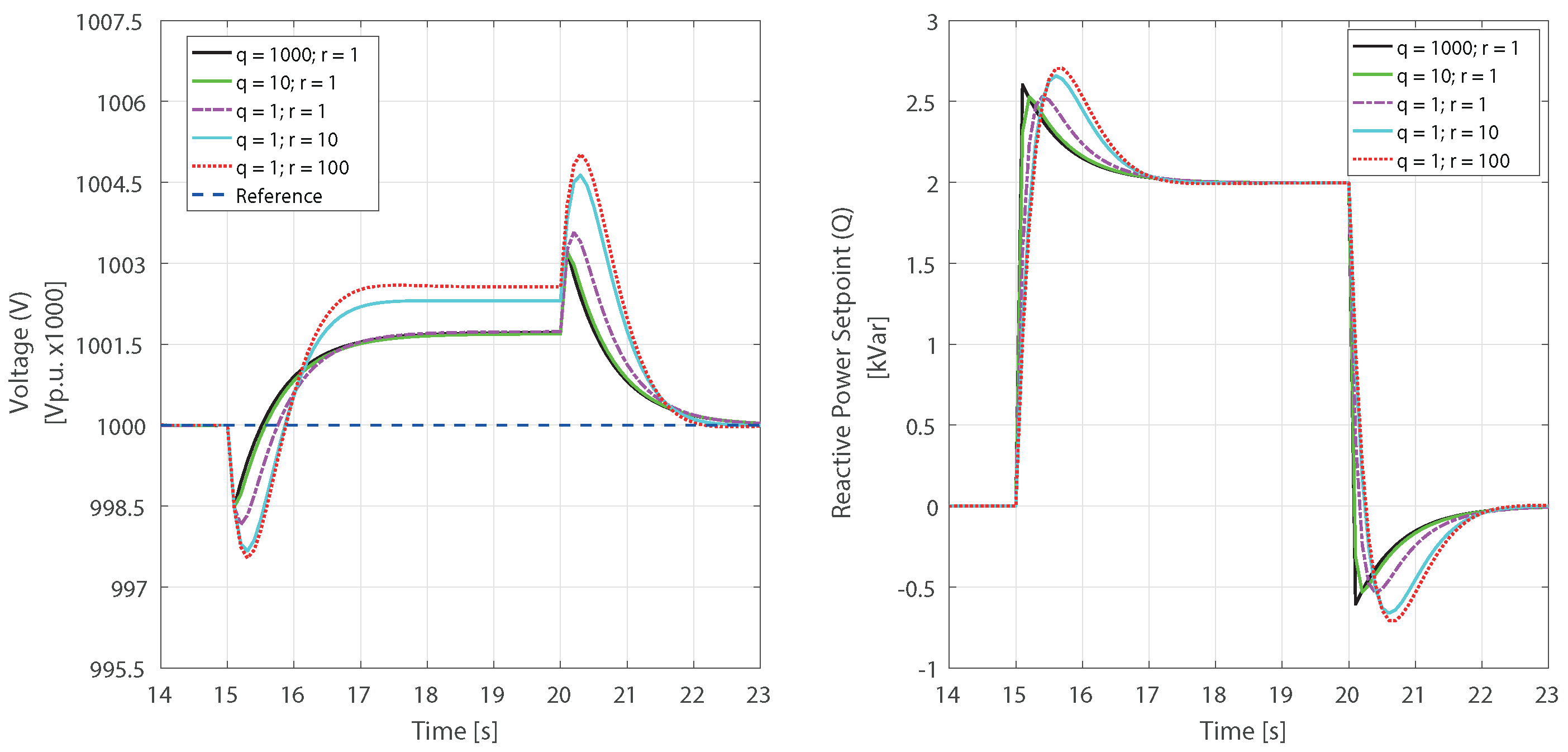
To evaluate the performance of the predictive voltage controller, considering irradiance and load variations, it was necessary to adjust the MPC scheme to achieve the response best fitted to the voltage regulation needs. This MPC tuning was developed through iterative variation of the control constraints, the prediction and control horizons, and the weighting parameters. The controller tuning test results for voltage (output) and reactive power (controlled input) are presented in
Figure 8, considering a step input disturbance of two kvar, starting at fifteen seconds of simulation and stopping after five seconds. The figures are zoomed in to the time range of the response results where the transient and stabilization behavior of the system is more evident.
As shown in
Figure 8, the MPC response exhibited lower overshoot behavior with a higher Q/R weight relation, but presented a slightly longer settling time in this condition. For microgrid voltage regulation in a secondary level, operating on the scale of seconds and minutes, key attributes are low overshoot and stable-state error response rather than very fast settling times, so Q and R weighting values of 10 and 1, respectively, were chosen from the tuning process as the optimal values to implement.
To establish the optimal MPC setting for the specific control problem tackled here, simulation tests of the modeled PV source were carried out to maintain a stable busbar voltage, considering the expected disturbances to be faced by the controller in an experimental implementation. The simulation tests were undertaken using the setting parameters in
Table 3, considering a target constant voltage of 1.0 Vp.u., in an allowable range of 0.9–1.1 Vp.u. as the Colombian regulation states. The system performance results for the proposed controller are shown in
Figure 9 for real external disturbances of solar irradiance and power demand conditions. The controller solutions derive from the predictive optimization of (
1) where the plant matrices are the state-space discretized representation of the model transfer functions (
4), (
5), and (
6).
The solar irradiance and load power disturbances considered for the controller test were experimental data gathered from the location where the physical PV system was operating in the UPB microgrid. These meteorological and electrical conditions, spanning 4200 s, allow the simulated MPC scheme to be evaluated in conditions similar to those that would occur in an experimental implementation.
The MPC performance results include the reactive power set-point (Q) calculated by the predictive controller for each time-step. This is the controlled variable of the regulation scheme and represents the reactive power command that would be sent to the respective inverter in an experimental implementation. As seen in
Figure 9, the Q set-point is mainly driven by the solar irradiance variation, so it is continuously calculated to face the voltage deviation, making use of the electrical relation between Q and V, where a negative value indicates reactive power consumption and consequent voltage reduction.
Regarding the simulated controller performance, although the solar irradiance presents frequent variations up to 600 W/m
2, as seen in
Figure 9, the voltage deviations with a regulation error up to 0.012% and a mean square error of
Vp.u.x1000 determine the successful operation of the MPC scheme. Even though the solar resource behavior has a significant effect on the busbar voltage, as seen in the natural performance and identification tests of the system, the continuous calculation of optimal reactive power values of the MPC logic enable voltage regulation around the 1.0 Vp.u. reference target.
The upper chart of
Figure 9, presenting the voltage response of the system, is greatly augmented on the y-axis scale to make clear the sharp and rapid effect of external disturbance variations considered in the MPC scheme. It is clear that strong fluctuations in solar irradiance (the third sub-figure from top to bottom), such as those presented at 100, 1750, 2550 to 2950, and 3400 to 4100 s of simulation, create brisk oscillations of voltage response that are quickly damped by the close-loop operation of the MPC to follow the 1.0 Vp.u reference. As noted, these strong disturbances only caused a 0.125 Vp.u.x1000 maximum deviation in voltage behavior.
The close relation between the solar irradiance and the busbar voltage identified in the experimental data indicates a strong effect of the PV source behavior on the electrical performance of the UPB microgrid node. The generated power, and curtailment of the grid imported power, are related to the voltage oscillations, while the PV inverters have a significant effect on voltage stabilization for low-voltage grids.
6. Conclusions
A methodology for modeling voltage behavior in a grid-tied campus microgrid was developed and tested through a model predictive control (MPC) scheme. Reactive power consumption and the contribution of a photovoltaic (PV) system were varied, and the solar radiation and electrical demand were measured as disturbances, and the voltage response collected. The generated model was integrated with a simulated MPC system for voltage regulation in a microgrid node with experimental data for external disturbances.
A low-order linear model was successfully obtained to represent the voltage behavior in the form of frequency-domain transfer functions. The model generated from experimental data measured in the UPB campus microgrid was able to reproduce the validation voltage response with an 88.4% fit.
In experimental modeling, such as that presented here, it is essential to consider the specific conditions and the limitations of the commercial devices involved in terms of their control variable characteristics. It is necessary to identify the setting parameters that can be manipulated with the physical resources, such as the power factor, and its relationship with the controlled variables required by the linear model, such as the reactive power, to develop automatic control systems.
The developed model predictive secondary voltage controller successfully regulated the reactive power of the manipulated resource to follow the constant node voltage target in a simulated environment, coping with experimental solar irradiance and power demand disturbances measured from the real-world UPB campus microgrid. The tested disturbances covered a wide range of up to 600 W/m2 for solar irradiance and 65 kW for power demand. The simulated controller exhibited high regulation precision with an error up to 0.012 % and a fast response, which is appropriate for secondary-layer voltage management in a hierarchical microgrid control strategy.
Future work will consider the integration of low-order linear models for different resources, obtained through the process presented in this paper, and the establishment of predictive control strategies for experimental secondary voltage control systems to regulate the node voltages of the physical UPB campus microgrid as part of a complete energy management system.
Author Contributions
Conceptualization, E.D.E. and T.M.; methodology, E.D.E. and T.M.; software, E.D.E. and T.M.; validation, E.D.E. and T.M.; formal analysis, E.D.E. and T.M.; investigation, E.D.E. and T.M.; writing—original draft preparation, E.D.E. and T.M.; writing—review and editing, T.M. and I.A.I.; supervision, I.A.I.; project administration, I.A.I. All authors have read and agreed to the published version of the manuscript.
Funding
This research was funded by the project: “Strategies for the transformation of the Colombian energy sector in the 2030 horizon—Energética 2030” financed by the research call 778 of MinCiencias Ecosistema Científico. Contract FP44842-210-2018.
Data Availability Statement
The data presented in this study are available on request from the corresponding author. The data are not publicly available due to the data use agreement of the funding project.
Acknowledgments
The authors would like to thank researchers Carlos Restrepo, Santiago Bustamante and Andrés Eusse and the whole Research Group on Transmission and Distribution of Electric Power (T&D) at the Universidad Pontificia Bolivariana for their support.
Conflicts of Interest
The authors declare no conflict of interest. The funders had no role in the design of the study; in the collection, analyses, or interpretation of data; in the writing of the manuscript, or in the decision to publish the results.
Abbreviations
The following abbreviations are used in this manuscript:
| AVR | Automatic Voltage Regulator |
| BESS | Battery Energy Storage System |
| DER | Distributed Energy Resource |
| DG | Distributed Generator |
| EMS | Energy Management System |
| ESS | Energy Storage System |
| HIL | Hardware In the Loop |
| LQR | Linear Quadratic Regulator |
| MILP | Mixed Integer Linear Programming |
| MIMO | Multiple-Input Multiple-Output |
| MOR | Model Order Reduction |
| MPC | Model Predictive Control |
| N4SID | Numerical Algorithms for Subspace State System Identification |
| NLS | Non-linear Least Square |
| NRMSE | Normalized Root Mean Squared Error |
| PCC | Point of Common Coupling |
| PE | Power Electronics |
| PF | Power Factor |
| PSOA | Particle Swarm Optimization Algorithm |
| RES | Renewable Energy Source |
| RHPC | Rolling Horizon Predictive Control |
| SCADA | Supervisory Control and Data Acquisition |
| UPB | Universidad Pontificia Bolivariana |
| VSC | Voltage Source Converter |
References
- Ojo, Y.; Watson, J.; Lestas, I. A Review of Reduced-Order Models for Microgrids: Simplifications vs Accuracy. arXiv 2020, arXiv:2003.04923. [Google Scholar]
- Hu, J.; Shan, Y.; Guerrero, J.M.; Ioinovici, A.; Chan, K.W.; Rodriguez, J. Model predictive control of microgrids—An overview. Renew. Sustain. Energy Rev. 2021, 136, 110422. [Google Scholar] [CrossRef]
- Espín-Sarzosa, D.; Palma-Behnke, R.; Núñez-Mata, O. Energy management systems for microgrids: Main existing trends in centralized control architectures. Energies 2020, 13, 547. [Google Scholar] [CrossRef] [Green Version]
- Shahgholian, G. A brief review on microgrids: Operation, applications, modeling, and control. Int. Trans. Electr. Energy Syst. 2021, 31, e12885. [Google Scholar] [CrossRef]
- Carpintero-Rentería, M.; Santos-Martín, D.; Guerrero, J.M. Microgrids literature review through a layers structure. Energies 2019, 12, 4381. [Google Scholar] [CrossRef] [Green Version]
- Wang, Y.; Rousis, A.O.; Strbac, G. On microgrids and resilience: A comprehensive review on modeling and operational strategies. Renew. Sustain. Energy Rev. 2020, 134, 110313. [Google Scholar] [CrossRef]
- Shi, Y.; Hu, S.; Xu, D.; Su, J.; Liu, N.; Yang, X.; Du, Y. A simplified microgrid voltage and frequency response characteristic modelling method based on system identification. Int. J. Electr. Power Energy Syst. 2020, 121, 106063. [Google Scholar] [CrossRef]
- John, T.; Lam, S.P. Voltage and frequency control during microgrid islanding in a multi-area multi-microgrid system. IET Gener. Transm. Distrib. 2017, 11, 1502–1512. [Google Scholar] [CrossRef]
- Villalón, A.; Rivera, M.; Salgueiro, Y.; Muñoz, J.; Dragičević, T.; Blaabjerg, F. Predictive control for microgrid applications: A review study. Energies 2020, 13, 454. [Google Scholar] [CrossRef]
- Bordons, C.; Garcia-Torres, F.; A. Ridao, M. Model Predictive Control of Microgrids; Springer: Berlin/Heidelberg, Germany, 2020. [Google Scholar] [CrossRef]
- Rawlings, J.B.; Mayne, D.Q.; Diehl, M.M. Model Predictive Control: Theory, Computation, and Design, 2nd ed.; Nob Hill Publishing, LLC: Santa Barbara, CA, USA, 2019. [Google Scholar] [CrossRef]
- Cai, C.; Liu, H.; Dai, W.; Deng, Z.; Zhang, J.; Deng, L. Dynamic equivalent modeling of a grid-tied microgrid based on characteristic model and measurement data. Energies 2017, 10, 1951. [Google Scholar] [CrossRef] [Green Version]
- Hu, Y.; Konakalla, S.A.R.; de Callafon, R.A. Covariance Based Estimation for Reduced Order Models of Microgrid Power Flow Dynamics. IFAC-PapersOnLine 2018, 51, 903–908. [Google Scholar] [CrossRef]
- Papadopoulos, P.N.; Papadopoulos, T.A.; Crolla, P.; Roscoe, A.J.; Papagiannis, G.K.; Burt, G.M. Measurement-based analysis of the dynamic performance of microgrids using system identification techniques. IET Gener. Transm. Distrib. 2015, 9, 90–103. [Google Scholar] [CrossRef] [Green Version]
- Conte, F.; D’Agostino, F.; Massucco, S.; Silvestro, F.; Bossi, C.L.; Cabiati, M. Experimental Validation of a Dynamic Equivalent Model for Microgrids. IEEE Trans. Ind. Appl. 2021, 57, 2202–2211. [Google Scholar] [CrossRef]
- Fonkwe, E.; Kirtley, J.; Almeida, M.; Medjo, D. Model identification of dynamic microgrids and controller optimization with high fidelity hardware-in-the-loop platform. In Proceedings of the 2016 IEEE 17th Workshop on Control and Modeling for Power Electronics COMPEL, Trondheim, Norway, 27–30 June 2016. [Google Scholar] [CrossRef]
- Yamashita, D.Y.; Vechiu, I.; Gaubert, J.P. Real-time Parameters Identification of Lithium-ion Batteries Model to Improve the Hierarchical Model Predictive Control of Building MicroGrids. In Proceedings of the 2020 22nd European Conference on Power Electronics and Applications, Lyon, France, 7–11 September 2020. [Google Scholar] [CrossRef]
- Shabbir, M.N.S.K.; Liang, X.; Li, W.; Imtiaz, S.; Quaicoe, J.E. A Novel Model Predictive Controller for Distributed Generation in Isolated Microgrids: Part I Development and Parameterization of the Data-Driven Predictive Model. IEEE Trans. Ind. Appl. 2022, 5844–5859. [Google Scholar] [CrossRef]
- Zhang, J.; Sun, Y.; Liu, M.; Dong, W.; Han, P. Research on modeling of microgrid based on data testing and parameter identification. Energies 2018, 11, 2525. [Google Scholar] [CrossRef] [Green Version]
- Zheng, D.d.; Sohail, S.; Karimi, A. Closed-loop data-driven modeling and distributed control for islanded microgrids with input constraints. Control Eng. Pract. 2022, 126, 105251. [Google Scholar] [CrossRef]
- Zhang, Y.; Wang, R.; Zhang, T.; Liu, Y.; Guo, B. Model predictive control-based operation management for a residential microgrid with considering forecast uncertainties and demand response strategies. IET Gener. Transm. Distrib. 2016, 10, 2367–2378. [Google Scholar] [CrossRef]
- Forel, A. Distributed Model Predictive Operation Control of Interconnected Microgrids. Ph.D. Thesis, KTH Royal Institute of Technology, Stockholm, Sweden, 2017. [Google Scholar]
- Sarantis, I. Robust Model Predictive Control Strategies in Fuel-Cell-Car-Based Microgrids. Ph.D. Thesis, Delft University of Technology, Delft, The Netherlands, 2017. [Google Scholar]
- Shan, Y.; Hu, J.; Li, Z.; Guerrero, J.M. A Model Predictive Control for Renewable Energy Based AC Microgrids Without Any PID Regulators. IEEE Trans. Power Electron. 2018, 33, 9122–9126. [Google Scholar] [CrossRef] [Green Version]
- Toman, R. Distributed Model Predictive Control of Power Converters in Microgrids Under Different Modes of Operation. Ph.D. Thesis, Western Michigan University, Kalamazoo MI, USA, 2017. [Google Scholar]
- Dragicevic, T. Model Predictive Control of Power Converters for Robust and Fast Operation of AC Microgrids. IEEE Trans. Power Electron. 2018, 33, 6304–6317. [Google Scholar] [CrossRef]
- Nurkanovic, A.; Mesanovic, A.; Zanelli, A.; Frison, G.; Frey, J.; Albrecht, S.; Diehl, M. Real-Time Nonlinear Model Predictive Control for Microgrid Operation. In Proceedings of the 2020 American Control Conference, Denver, CO, USA, 1–3 July 2020; pp. 4989–4995. [Google Scholar] [CrossRef]
- Farina, M.; Guagliardi, A.; Mariani, F.; Sandroni, C.; Scattolini, R. Model predictive control of voltage profiles in MV networks with distributed generation. Control Eng. Pract. 2015, 34, 18–29. [Google Scholar] [CrossRef] [Green Version]
- Zeng, P.P.; Wu, Z.; Zhang, X.P.; Liang, C.; Zhang, Y. Model predictive control for energy storage systems in a network with high penetration of renewable energy and limited export capacity. In Proceedings of the 2014 Power Systems Computation Conference PSCC, Wroclaw, Poland, 18–22 August 2014. [Google Scholar] [CrossRef]
- Falahi, M.; Butler-Purry, K.; Ehsani, M. Dynamic reactive power control of islanded microgrids. IEEE Trans. Power Syst. 2013, 28, 3649–3657. [Google Scholar] [CrossRef]
- Shabbir, M.N.S.K.; Liang, X.; Li, W.; Imtiaz, S.; Quaicoe, J. A Novel Model Predictive Controller for Distributed Generation in Isolated Microgrids: Part II Model Predictive Controller Implementation. IEEE Trans. Ind. Appl. 2022, 5860–5870. [Google Scholar] [CrossRef]
- Najafzadeh, M.; Strzelecka, N.; Husev, O.; Roasto, I.; Nassereddine, K.; Vinnikov, D.; Strzelecki, R. Grid-Forming Operation of Energy-Router Based on Model Predictive Control with Improved Dynamic Performance. Energies 2022, 15, 4010. [Google Scholar] [CrossRef]
- Mestriner, D.; Rosini, A.; Xhani, I. Primary Voltage and Frequency Regulation in Inverter Based Islanded Microgrids through a Model Predictive Control Approach. Energies 2022, 15, 5077. [Google Scholar] [CrossRef]
- Liu, S.; Zhang, L.; Wu, Z.; Zhao, J.; Li, L. Improved Model Predictive Dynamic Voltage Cooperative Control Technology Based on PMU. Front. Energy Res. 2022. [Google Scholar] [CrossRef]
- Wang, L.; Dubey, A.; Gebremedhin, A.H.; Srivastava, A.; Schulz, N. MPC-Based Decentralized Voltage Control in Power Distribution Systems with EV and PV Coordination. IEEE Trans. Smart Grid 2022, 13, 2908–2919. [Google Scholar] [CrossRef]
- Parisio, A.; Rikos, E.; Glielmo, L. A model predictive control approach to microgrid operation optimization. IEEE Trans. Control Syst. Technol. 2014, 22, 1813–1827. [Google Scholar] [CrossRef]
- Elkazaz, M.; Sumner, M.; Naghiyev, E.; Pholboon, S.; Davies, R.; Thomas, D. A hierarchical two-stage energy management for a home microgrid using model predictive and real-time controllers. Appl. Energy 2020, 269, 115118. [Google Scholar] [CrossRef]
- Elkazaz, M.; Sumner, M.; Thomas, D. Energy management system for hybrid PV-wind-battery microgrid using convex programming, model predictive and rolling horizon predictive control with experimental validation. Int. J. Electr. Power Energy Syst. 2020, 115, 105483. [Google Scholar] [CrossRef]
- Manrique, T.; Fiacchini, M.; Chambrion, T.; Millerioux, G. MPC-based tracking for real-time systems subject to time-varying polytopic constraints. Int. J. Robust Nonlinear Control. 2016, 37, 708–729. [Google Scholar] [CrossRef]
| Publisher’s Note: MDPI stays neutral with regard to jurisdictional claims in published maps and institutional affiliations. |
© 2022 by the authors. Licensee MDPI, Basel, Switzerland. This article is an open access article distributed under the terms and conditions of the Creative Commons Attribution (CC BY) license (https://creativecommons.org/licenses/by/4.0/).


