Article

Performance Analysis of a Hydrogen-Doped High-Efficiency Hybrid Cycle Rotary Engine in High-Altitude Environments Based on a Single-Zone Model

1
Science and Technology on Plasma Dynamics Laboratory, Air Force Engineering University, Xi’an 710038, China
2
Institute of Aero-Engine, School of Mechanical Engineering, Xi’an Jiaotong University, Xi’an 710049, China
*
Author to whom correspondence should be addressed.
Energies 2022, 15(21), 7948; https://doi.org/10.3390/en15217948
Submission received: 12 September 2022 / Revised: 10 October 2022 / Accepted: 18 October 2022 / Published: 26 October 2022
(This article belongs to the Section A5: Hydrogen Energy)

Abstract

:
The power attenuation of internal combustion engines in high-altitude environments restricts the performance of unmanned aerial vehicles. Herein, a single-zone model of a hydrogen-doped high-efficiency hybrid cycle rotary engine that considers high-altitude environments was proposed. The indicated values for power, thermal efficiency, and specific fuel cost were used to evaluate the power performance, energy conversion efficiency, and economic performance of the engine, respectively. Then, the effects of adjusting the hydrogen fraction, ignition angle, and rotational speed on high-altitude performance were analyzed. The results showed that high-altitude environments prolonged combustion duration and reduced in-cylinder pressure, thereby causing power attenuation; however, increasing the hydrogen fraction can increase the indicated power. At an altitude of 6 km, the indicated power with a hydrogen fraction of 0.3 was approximately 20.7% higher than that obtained with pure gasoline. The ignition angle and hydrogen fraction corresponding to the optimal indicated thermal efficiency increased with increasing altitude. At an altitude of 6 km, the indicated thermal efficiency reached its maximum (36.4%) at an ignition angle of 340 [CA°] and a hydrogen fraction of 0.15. At high altitudes, rotational speeds below 6000 rpm and ignition angles of 340–345 [CA°] were beneficial in reducing indicated specific fuel costs.

1. Introduction

The internal combustion engine has the advantages of a simple structure, small volume, and large power density [1]; thus, it is widely used in unmanned aerial vehicle (UAV) power systems [2]. Furthermore, the associated low manufacturing cost enables the production of internal combustion engines in batches [3]. However, the decreases in air intake, pressure, and temperature in high-altitude environments results in a combustion lag and a decrease in power and economic performances [4]. To expand the advantages of the internal combustion engine and to compensate for its weakness in terms of decreasing high-altitude performance, it is necessary to seek a novel power system.
The Wankel engine is a power system with a specialized structure [5] which can efficiently alleviate the power attenuation of the reciprocating internal combustion engine in high-altitude environments [6]. Instead of the piston, as in the reciprocating internal combustion engine, a triangular rotor is adopted in Wankel engines to drive the crankshaft to output power [7,8].
Compared to the reciprocating internal combustion engine, the Wankel engine has a simpler transmission structure and a higher power [9], which makes it suitable for drones, motor vehicles, and small generators [10]. However, its poor combustion performance caused by the long and narrow combustion chamber increases fuel consumption and emissions [11], which leads to poor thermal efficiency and economic performance [12]. Therefore, the Liquid Piston Company proposed a novel “X” type rotary engine [13] and successively developed the “X1,” “XMv2,” “XMv3,” “X4,” “XMD,” and other models. Compared to the Wankel engine, the combustion chambers of the “X” type rotary engine are arranged in fixed circumferential directions around the cylinder [14,15]. In addition, the “X” type rotary engine adopts a four-stroke high-efficiency hybrid cycle (HEHC), which is a thermodynamic cycle [16]. It has a higher potential for thermodynamic efficiency [17] and is an ideal UAV power system.
Moreover, much effort has been made to study the high-altitude performance of internal combustion engines. Perez et al. [18] analyzed the effects of oxygen enrichment on engine performance in a plateau environment on a single-rotor, air-cooled, naturally aspirated diesel engine. They found that at an altitude of 2600 [m], oxygen-enriched air alleviated the decline in engine power, effectively preventing the deterioration of brake-specific fuel consumption. Wang [19] studied the control strategy of high-altitude engine operation through a genetic algorithm; he conducted multi-objective optimization on fuel consumption and emissions, achieving a 0.67% reduction in fuel consumption.
In addition, multi-fuel combustion is an efficient method to improve high-altitude performance. Fossil fuels such as gasoline, diesel, and kerosene [20] are commonly used in Wankel engines, as they have a slow combustion rate and long combustion period, especially in long and narrow combustion chambers and high-altitude environments [21]. Hydrogen is a feasible alternative fuel with the characteristics such as a low ignition energy and a short extinguishing distance [22]. It can be used to effectively shorten the combustion period of the engine and improve its high-altitude performance [23]. However, most research on hydrogen doped internal combustion engines has been carried out in ground environments with engine applications in automobiles and generators.
Su et al. [24] investigated the effects of hydrogen enrichment on the performance of the Wankel engine through experiments. The results showed that an increase in the hydrogen fraction could improve engine performance. This effect was more pronounced when the hydrogen fraction was below 0.10. Shi et al. [25] discussed the effects of an excess air ratio and hydrogen fraction on engine combustion and emission performance under lean-burn conditions. It was found that adding more hydrogen resulted in a lower brake thermal efficiency. Moreover, a large excess air ratio and a small hydrogen fraction could improve thermal efficiency. Amrouche et al. [26] investigated the effects of hydrogen on the combustion characteristics of a gasoline Wankel engine. The results showed that hydrogen was effective in decreasing the central heat release, thus improving the efficiency of the combustion process. Furthermore, the increase of hydrogen in the intake can reduce cooling losses. Yang et al. [27] studied the combustion performance under different conditions of hydrogen injection timing and duration. It was found that at a hydrogen injection timing of 110 [CA°] before top dead center (BTDC) and hydrogen injection duration of 40 [CA°], a faster flame speed was obtained and the carbon monoxide emission was reduced, effectively improving the engine performance.
At present, the development of a novel HEHC rotary engine is still in its infancy, and there are few studies on the high-altitude performance of hydrogen–gasoline dual-fuel HEHC rotary engines. As simulations are an effective means of establishing virtual prototypes, they can be used to aid in the design, pre-study, and validation of applications after evaluation using experimental data. In our study, a single-zone homogenization model of the HEHC rotary engine in high-altitude environments was established. Then, the effects of the hydrogen fraction, rotational speed, and ignition angle on the engine’s high-altitude performance were analyzed. Our work provides a foundation to explore the applications of hydrogen–gasoline dual-fuel HEHC rotary engines for UAV power systems.

2. Modeling

2.1. Engine Description

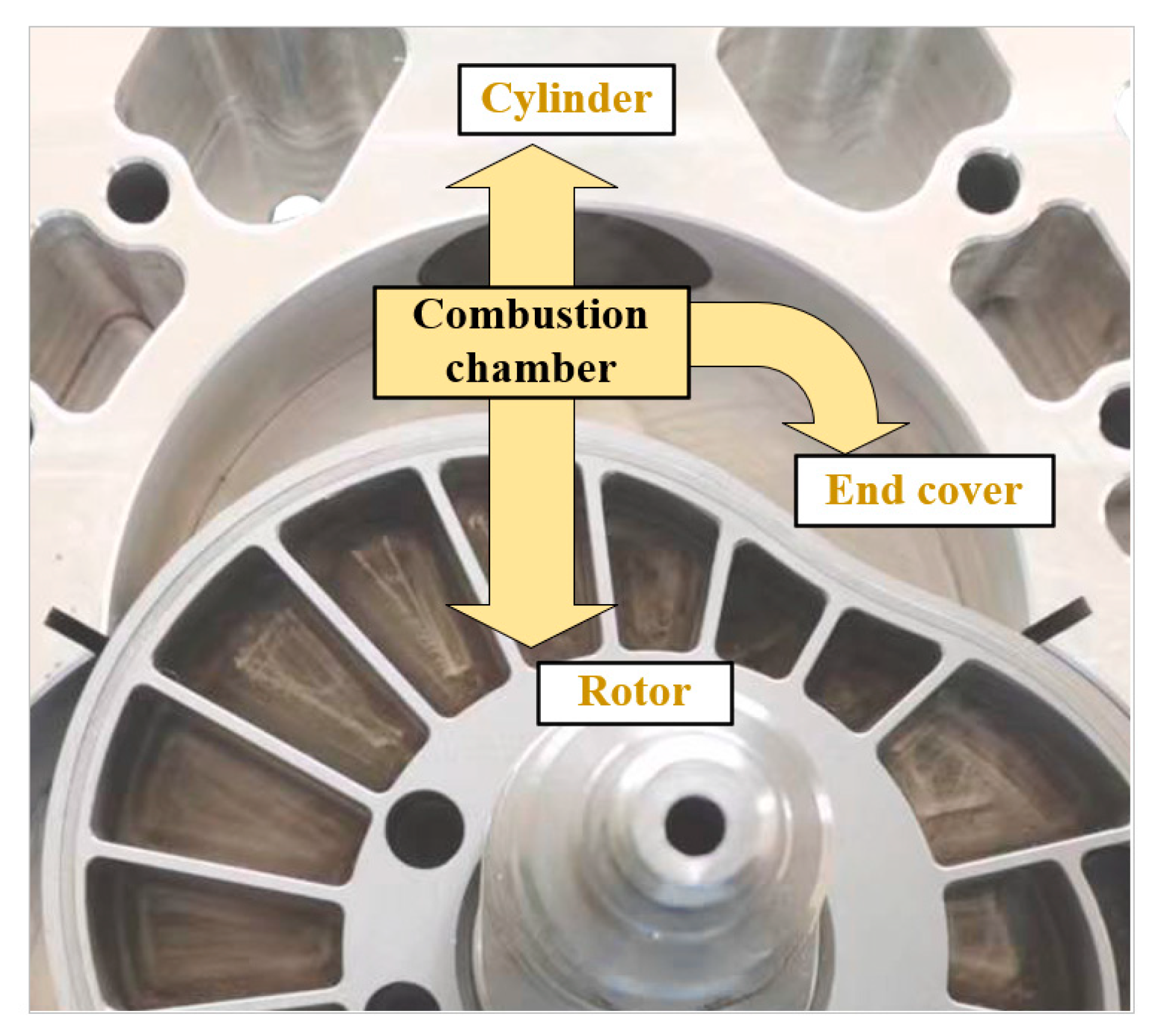
The high-efficiency hybrid cycle is a four-stroke cycle. As shown in Figure 1, the HEHC rotary engine using the high-efficiency hybrid cycle has an oval rotor with a triangular shell, and the intake and exhaust channels are arranged on the rotor, which is the opposite to the case of the Wankel engine. The combustion chamber is fixed, which is similar to that of a piston engine [28]. When the “8” type rotor reaches the top dead center, the surfaces of the rotor and the cylinder are theoretically completely fitted, and the pit is the only area of the combustion chamber [15]. The special structure enables it to maintain constant volume combustion for a long time near the top dead center to improve thermal efficiency. Furthermore, the Wankel engine has the same compression and expansion ratios. However, in a high-efficiency hybrid cycle, the expansion ratio is greater than the compression ratio, and the overexpansion can extract more energy from the combustion. Table 1 compares the structural characteristics of reciprocating, Wankel, and HEHC rotary engines.
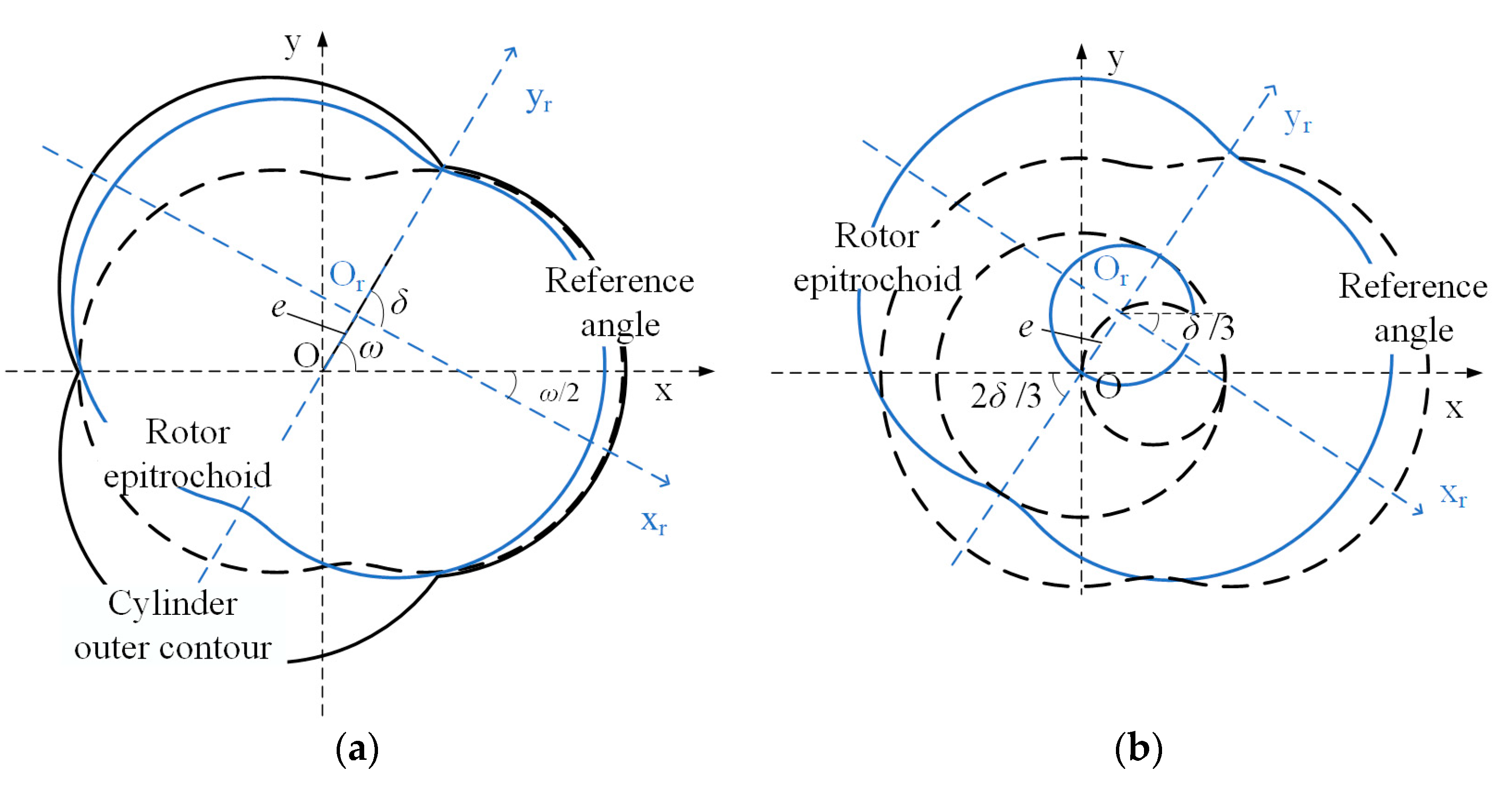
The engine profile is key to the structural design of the rotary engine. In the case of the HEHC rotary engine, the outer envelope line of the helix is adopted as the profile of the cylinder, as shown in Figure 2, which is simply the reverse in the case of the Wankel engine [29]. δ is the characteristic angle in the xr-or-yr coordinate system, while ω is the characteristic angle in the x-o-y coordinate system. Table 2 lists the profile equations of the cylinder and rotor, which are calculated by the eccentric distance e and generation radius Rg.
The engine used to establish the model in our study was a naturally aspirated, single-rotor, air-cooled HEHC rotary engine. Gasoline and hydrogen were injected from the fuel injectors and mixed with the air in the intake tract. Then, the mixture entered the combustion chamber through the internal passages of the rotor. Due to the advanced blending and rotation of the rotor, the fuel and air were considered to be fully mixed before combustion. The input parameters under the design condition are shown in Table 3. Vpit represents the volume of the external spherical combustion chamber. The displacement Vd is the difference between the maximum and minimum volumes of the combustion chamber. The operating environment of the engine was a standard atmosphere, with a pressure of 101.325 [kPa] and temperature of 288.15 [K].

2.2. Single-Zone Homogenization Model

As the three combustion chambers of the HEHC rotary engine were symmetrically distributed in the circumferential direction with a difference of 120 [CA°] in the work in progress, at this stage, only one combustion chamber was selected as the research object to establish the single-zone thermodynamic system. In addition, the homogenization model was used in the system, which implies that the composition and thermodynamic parameters of the working fluid were the same at each position in the system [30].
The following assumptions were applied to the system to simplify the model: (a) the thermodynamic parameters of the working fluid are affected by the in-cylinder environment; (b) the mechanical loss of the engine is ignored; (c) the overlapping angle of the intake and exhaust is 0; and (d) the system works in a steady state. Figure 3 shows the mass flow and energy flow of the system. The conservation equations are expressed as Equations (1) and (2) [8].
d m sys = d m in + d m f d m l d m out
d ( m s y s u ) = d Q b + h i n d m i n + h f d m f h l d m l h o u t d m o u t d Q e d Q v P s y s d V s y s
where m is the mass; Q is the quantity of heat; the subscript sys represents the combustion chamber system; msys·u represents the internal energy of the system; the subscripts in, f, l, e, v, and out represent intake, fuel, leakage, heat exchange, exhaust, and fuel vaporization, respectively; and PsysdVsys represents the volume work.
A single-zone model considering the thermodynamic subsystems (leakage, heat exchange, combustion, and volume work) was built using MATLAB/SIMULINK, as shown in Figure 4. The output parameters (in-cylinder temperature, in-cylinder pressure) were re-entered into the subsystems by the feedback mechanism to obtain real-time results.

2.3. Model Equation

2.3.1. Gas State and Physical Property Parameters

The air was assumed to be a combination of N2, O2, CO2, and H2O. Combustion is the process in which the fuel consumes O2 to produce the final products H2O and CO2. The in-cylinder gas parameters were calculated by the equation of ideal gas state [31],
P sys V sys = m sys R T sys
where Psys, Vsys, and Tsys represent the pressure, volume, and temperature of the system, respectively; R represents the gas constant, which is determined by the gas composition and is obtained from the REFPROP database. The change in temperature is calculated by
d T s y s = 1 m s y s C v [ d ( m s y s u ) u d m s y s m s y s d u ]
where Cv is the specific heat capacity at a constant volume in terms of the working fluid.

2.3.2. Combustion

The mass of doped hydrogen is necessary to calculate the combustion heat; it is calculated by the equal equivalence ratio method, which indicates that the air consumed by the doped hydrogen is equal to that consumed by gasoline when replaced. The reaction equations of dual-fuel combustion without considering the intermediate reactions are expressed as Equations (5) and (6).
C x H y + ( x + y 4 ) O 2 x C O 2 + y 2 H 2 O
z H 2 + z 2 O 2 z H 2 O
The mass of the hydrogen can be calculated by
m h y d = 4 x + y 12 x + y m g a s H f
where the subscripts hyd and gas represent hydrogen and gasoline, respectively; Hf is the hydrogen fraction, which is the ratio of the gasoline replaced by hydrogen mgas_1 to the original total gasoline mgas_2
H f = m g a s _ 1 m g a s _ 2
The law of combustion and heat release of system was considered to follow the Wiebe semi-empirical equation model [32,33]. The dual Wiebe model was used to simulate dual-fuel combustion. It was assumed that the fuel and air were premixed, and the hydrogen and gasoline had the same combustion start angle.
dQ b = i = 1 2 H u i m f ,   i d f ( x i )
df ( x ) = c m c + 1 φ s ( φ φ 0 φ s ) m c exp ( c ( φ φ 0 φ s ) m c + 1 ) d φ
where Qb is the heat release of combustion; Hu is the low heat value of the fuel, and the low heat values of hydrogen and gasoline are 119.6 [MJ/kg] and 44.0 [MJ/kg], respectively; f(x) is the fuel consumption fraction of the fuel; the subscript i represents the fuel type; mc is the combustion quality and is taken as 3 [34]; c is the Wiebe coefficient and is taken as −6.908, which means that 99.9% of the fuel is consumed after combustion; φ0 is the combustion start angle and is assumed to be the ignition angle; and φs is the combustion duration angle, which is positively related to the rotational speed and negatively related to the flame propagation velocity.
φ s = φ s , d e s n 7000 v d e s v
where the subscript des represents the design condition of the engine, calibrated by the CFD model, and v is the flame propagation velocity.
In high-altitude environments, low temperatures and pressures are not conducive to the development of the flame, while the low air density increases the equivalence ratio of the combustible gas, which is beneficial for flame propagation [35]. The flame propagation velocity is calculated by
v = v des ( P s y s P d e s ) 0.22 ϕ 0.38 ( T s y s T d e s ) 2.18 0.8 ϕ
where ϕ is the equivalence ratio.

2.3.3. Heat Exchange

The heat exchange between systems and components is a complex and unstable process, which is generally simplified as a convective heat exchange process. As shown in Figure 5, there are three pathways for heat exchange between the combustion chamber and the engine: the working surface of the rotor, the inner surface of the cylinder, and the side of the end cover [36].
The temperatures of these components are considered constant when the system is in stable operation. The heat exchange rate is calculated by the Woschni model [37]:
d Q e = π 30 n ( 2 α end A end ( T T end ) + α r A r ( T T r ) + α c A c ( T T c ) ) d φ
where A is the area of heat exchange; the subscripts end, r, and c represent the end cover, rotor, and cylinder, respectively; and α is the heat exchange coefficient, calculated by
α = N u λ D h
where λ is the gas thermal conductivity; Dh is the qualitative scale of the engine; and Nu is the Nusselt number, calculated by the empirical equation [34], expressed as
N u = 0.023 R e 0.8 P r 0.43
where Re is the Reynolds number and Pr is Prandtl number.
The area of heat exchange is derived from the profile equations shown in Table 2, calculated by
A e nd = 2 e 2 [ π 3 + 2 K 2 9 3 3 2 K cos ( φ ) + ( 2 9 K 2 + 4 ) sin 1 ( 3 e R g ) ] A r = B φ 2 π 3 φ 2 + π 3 [ x r ' ( δ ) ] 2 + [ y r ' ( δ ) ] 2 d δ A c = 1 3 B [ x ' ( δ ) ] 2 + [ y ' ( δ ) ] 2 d δ + π ( 3 2 π V p i t ) 2 3
where φ is the crankshaft angle and Rg is the generation radius, which is the product of K and e.

2.3.4. Gas Leakage

Gas leakage has a significant impact on the performance of a HEHC rotary engine. Therefore, the design of the leakage subsystem is essential. In contract to the intake and exhaust, the gas leakage sub-model is the primary quality-correction model of the system and runs continuously. The two leakage flows (end-face leakage, tip leakage) are the main pathways of mass exchange in the system. Among them, tip leakage accounts for a larger proportion and is affected by the explosion pressure and phase difference of combustion chambers [38].
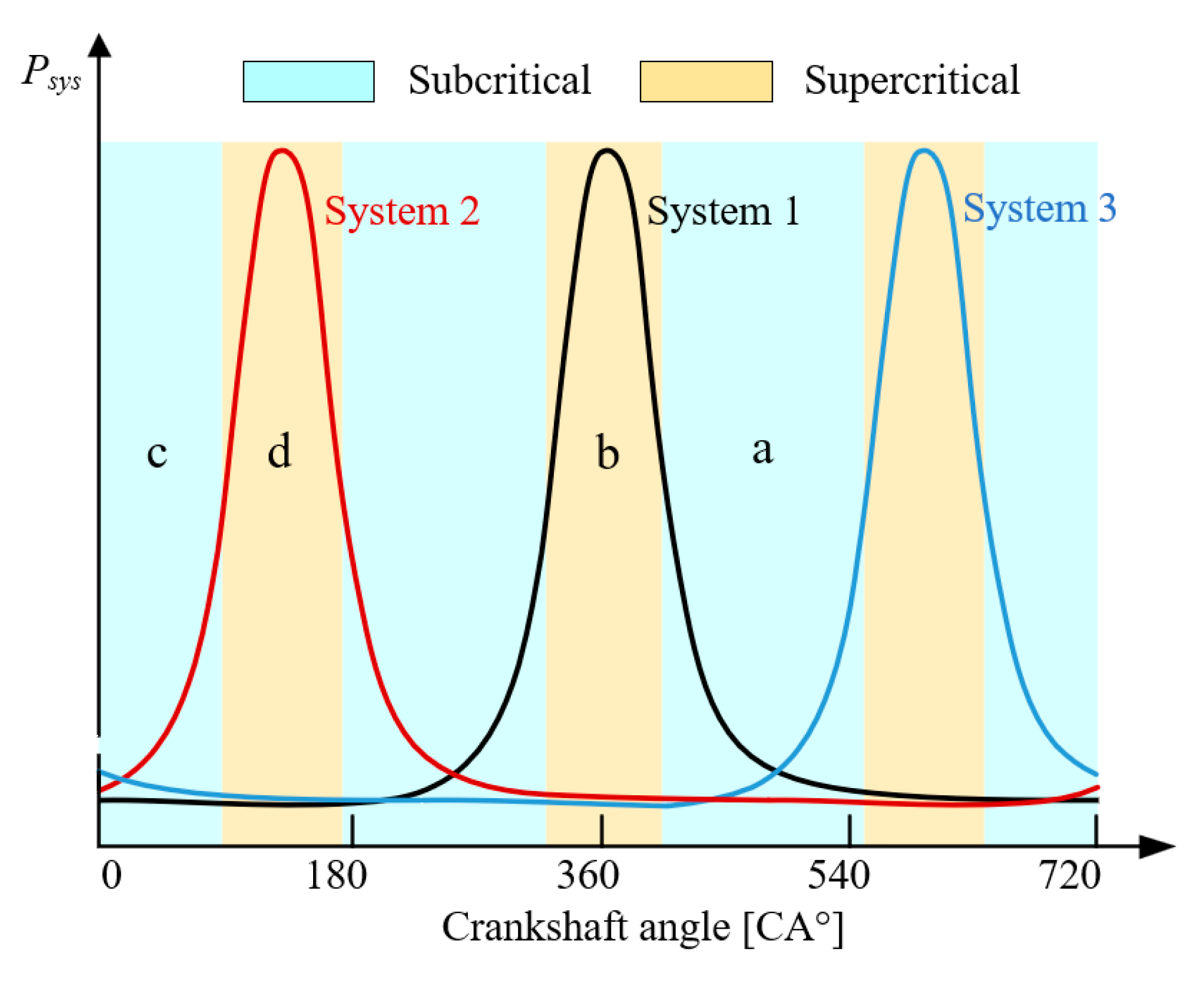
The gas leakage was considered to be an isentropic flow process in which the working fluid in the object system enters the adjacent system through the leakage gap [34], assumed to be a rectangular equivalent hole with an area of Al. Figure 6 shows the relationship between leakage state, pressure, and phase angle. Adjacent systems 1 and 2 are taken as examples, and Table 4 gives the state and calculation equations of leakage flow for two periods, a and b. It is worth noting that the pressure changes of the three systems distributed circumferentially were periodic with a phase difference of 120 [CA°] [39]. Thus, the mass of the object system increased at certain periods, such as periods c and d in Figure 6.
In Table 4, n is the rotational speed, σ is the leakage coefficient, γ is the adiabatic index, and M is the gas molar mass.

2.3.5. High-Altitude Environment

Changes in pressure, temperature, and density with altitude H are obtained from the following equation:
P 0 = 101.325 [ 1 0.0255 H 1000 ( 6357 6357 + H 1000 ) ] 5.256 kPa T 0 = 288.15 K 0.6 H 100 K ρ 0 = 1.293 P 0 101.325 273.15 T 0 kg / m 3

2.4. Evaluation Parameters

To evaluate the performance of the HEHC rotary engine, three metrics were used in our work. The power performance of the engine is represented by the indicated power, as shown in the following Equation:
P i = n P d V 30 S
where Pi is the indicated power, regardless of the friction mean effective pressure; S is the engine equivalent stroke, with the number ratio of the stroke to the combustion chamber set to 4/3, as shown in Table 1.
The energy conversion efficiency is characterized by the indicated thermal efficiency η:
η = P d V i = 1 2 H u i m f ,   i
A concept parameter indicated that the specific fuel cost Cf is introduced to evaluate the economic performance of the engine and is expressed as the cost of fuel consumed per kilowatt hour, calculated by the following equation
C f = I S F C [ ( 1 H f ) P c g a s + H f 2 x + y 12 x + y P c h y d ]
where ISFC is the indicated specific fuel consumption and Pc is the price of fuel, affected by various factors, such as time and region. To ensure the timeliness of the research data, the latest average prices for hydrogen and gasoline in North China were used as the calculation criteria in our paper, with these being 8.503 [$/kg] and 0.929 [$/kg], respectively.

3. Results and Discussion

A number of key operating parameters (ignition angle, rotational speed, and hydrogen content) were selected to study the high-altitude performance of the HEHC rotary engine. Table 5 details the operating parameters of the various cases chosen for the study on performance parameters. It should be noted that the effect of rotational speed on power was significant and essentially linear; thus, in Section 3.3.1, more content is devoted to the effect of the altitude, ignition angle, and hydrogen fraction on the indicated power. The same situation applies to the study of the effect of the hydrogen fraction on the indicated specific fuel cost in Section 3.3.3.

3.1. Model Verification

The model was verified by the experiments on a XMv3 rotary engine conducted at a dynamometer test facility of the Liquid Piston Company [36], as shown in Figure 7. In the experiments, the test intake pressures were 1.03 [bar] and 1.01 [bar], respectively. Gasoline was used as the engine fuel, and the equivalence ratio was set to 0.85. The in-cylinder pressure curves under two operating conditions of 5000 [rpm] and 9000 [rpm] were obtained. The calculated value of the maximum error of the model was 4.2%. The simulated data fitted well with the experimental data, and the use of the single-zone model to predict the working state of the HEHC rotary engine was found to be feasible. It is worth noting that the effect of the complex flow of gas in the cylinder on the flame could be considered in the homogenization model. As a result, compared to the measured pressure, the simulated pressure at high rotational speeds was slightly delayed at the ignition moment.

3.2. Effects of Operating Parameters on the High-Altitude Working State

There is little research on the high-altitude performance of internal combustion engines, especially HEHC rotary engines, making the relationships between various parameters unclear. Therefore, it was necessary to study the effects of operating parameters on the state parameters of the combustion chamber (combustion duration angle, in-cylinder pressure) for the exploration of engine performance, as described in the next section.

3.2.1. Combustion Duration Angle

The combustion duration angle was an important parameter in the Wiebe combustion model and was directly influenced by the altitude and operating parameters. Figure 8 shows the effect of operating parameters on the combustion duration angle at different altitudes. At high altitudes, especially above 2 [km], the low temperature and low pressure significantly inhibited the combustion activity, which increased the combustion duration angle. In Figure 8a, under the pure gasoline condition, when the engine worked at 6 [km], the combustion duration angle even reached 92.0 [CA°], 88.5% higher than that at 0 [km]. When hydrogen with low activation energy was doped, the fuel combustion reaction became more intense. As a result, the combustion duration angle was significantly shortened at high hydrogen fractions, and the improvement effect was more noticeable at higher altitudes. At a hydrogen fraction of 0.3, the negative effects of the environment were moderated by the hydrogen and high equivalence ratio, and the combustion duration angle at an altitude of 6 [km] was reduced to 26.5 [CA°]. Moreover, delayed ignition (closer to top dead center) could provide a higher initial temperature and pressure for combustion, with this being another method that can be to solve the problem of long-term combustion at high altitudes. At an altitude of 6 [km], the combustion duration angle at an ignition angle of 360 [CA°] was 49.3 [CA°], only 53.9% of that at an ignition angle of 330 [CA°]. It is worth mentioning that late ignition also delays the end angle of combustion, which could weaken the engine’s isovolumetric combustion and reduce the engine’s ability to work. This situation is explored in Section 3.3. As such, the adjustment effect of the ignition angle is limited. Compared to the above parameters, the rotational speed affects the combustion duration angle directly, essentially changing it linearly, as shown in Figure 8c.

3.2.2. In-Cylinder Pressure

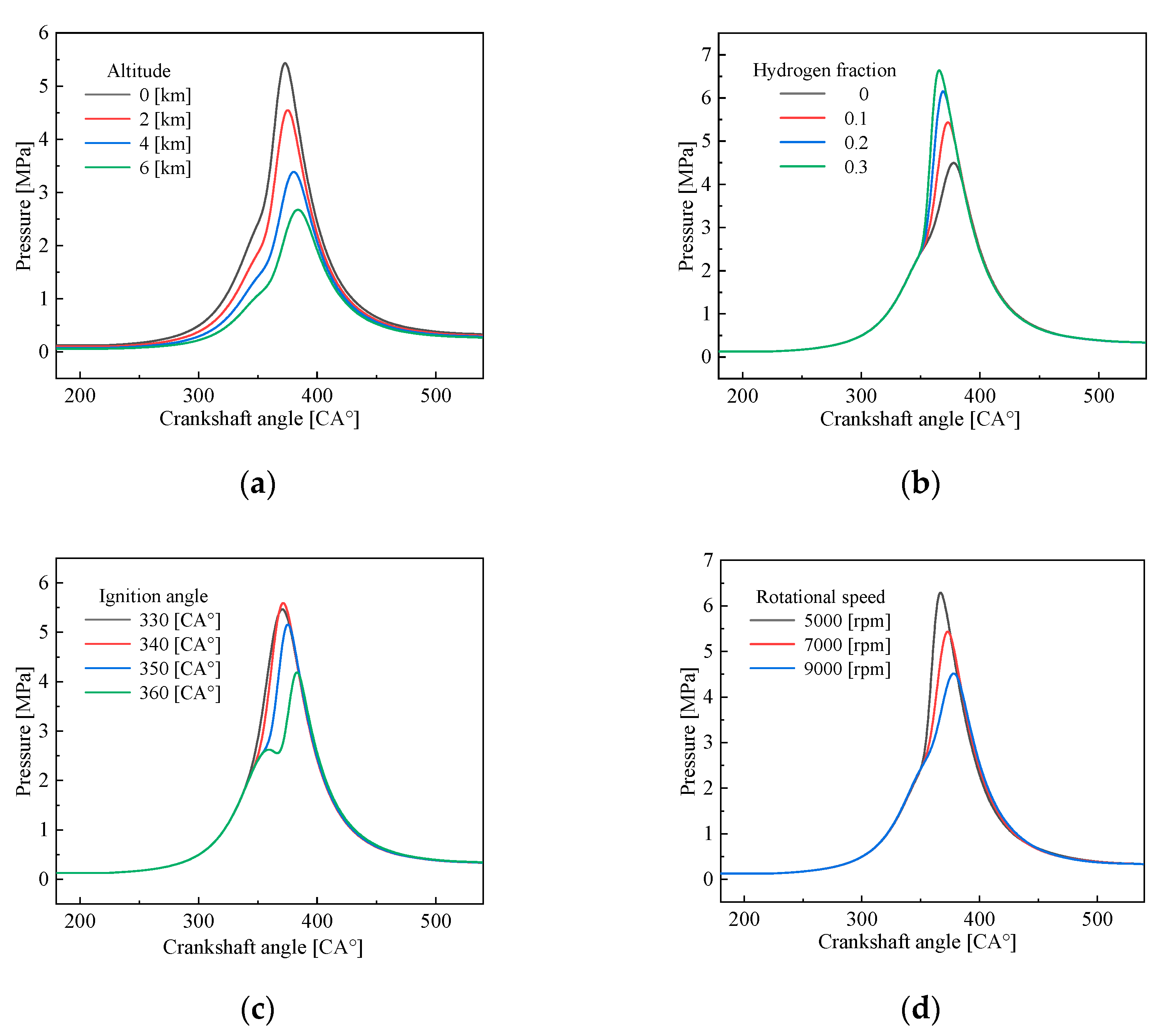
Figure 9 shows the variations in in-cylinder pressure with operating parameters. As shown in Figure 9a, the slow combustion at high altitudes delayed the rise of pressure and decreased the peak pressure significantly, reducing the engine’s power performance. At an altitude of 6 [km], the peak pressure appeared at 385 [CA°], approximately 2.7 [MPa], which was 12 [CA°] later and 51.0% lower than that at 0 [km]. As shown in Figure 9b, the increased hydrogen with a high heat value increased the combustion heat and shortened the combustion process. The peak pressure was 6.6 [MPa] at a hydrogen fraction of 0.3, which was 2.1 [MPa] higher than that under the pure gasoline condition. However, it occurred at 365 [CA°], too close to the top dead center, which was not conducive to converting energy into mechanical energy, leading to unstable operation. Figure 9c shows that as the ignition angle increased from 330 [CA°] to 340 [CA°], although the ignition was delayed, the compression process provided a higher start-combustion pressure and temperature, thus accelerating the combustion reaction. As a result, the peak pressure at 340 [CA°] reached 5.6 [MPa], slightly higher than that at 330 [CA°]. At an ignition angle of 360 [CA°], combustion started at the top dead center of the engine. The combustion chamber volume increased, while the heat release in the initial stage of combustion was low. Therefore, there was a decrease in cylinder pressure between 360 [CA°] and 367 [CA°]. In Figure 9d, the high rotational speed made the pressure rise slowly and decreased the peak pressure. At a rotational speed of 9000 [rpm], the peak pressure of 4.5 [MPa] occurred at 378 [CA°], 28.6% lower and 10 [CA°] later than that at 5000 [rpm], respectively.

3.3. Effects of Operating Parameters on High-Altitude Performance

3.3.1. Indicated Power

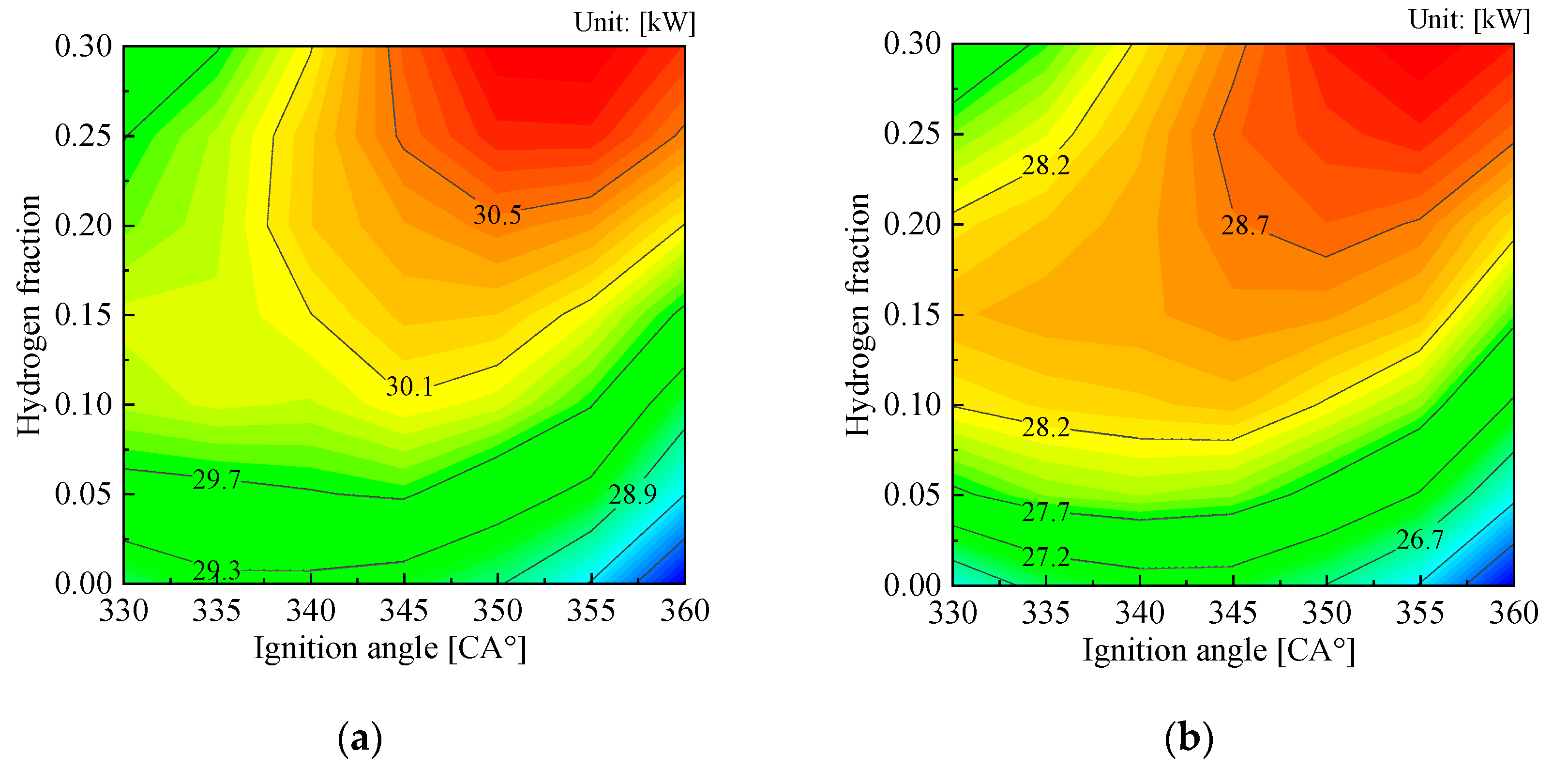
Figure 10 shows the effects of the ignition angle and hydrogen fraction on the indicated engine power at different altitudes. The indicated power generally increases as the hydrogen fraction increases because the doped hydrogen increases the heat release of combustion. In Figure 10a, at an altitude of 0 [km], under the pure gasoline condition, with the ignition angle increasing from 330 [CA°] to 360 [CA°], the indicated power decreased from 29.0 [kW] to 27.7 [kW], which was roughly 4.5%. This was because the slow combustion speed of gasoline, coupled with the delay in the ignition angle, made the pressure unable to be fully used for expansion work. As the hydrogen fraction increased, the central heat release of combustion advanced, and the power changed parabolically. At a hydrogen fraction of 0.15, the indicated power reached a maximum of 30.2 [kW] at 345 [CA°]. In particular, the flame propagation velocity was significantly increased at high hydrogen fractions, and premature ignition can cause a small volume and a large pressure in the cylinder at the same time, resulting in a low volume of work (PdV in Equation (2)) and the combustion to move away from the ideal working position. Therefore, under the condition of a 0.3 hydrogen fraction, the indicated power at an ignition angle of 330 [CA°] was 1.3 [kW] lower than that at an ignition angle of 360 [CA°], which was equivalent to that of the pure gasoline condition, indicating that hydrogen loses its improving effect.
With the increase in altitude, the density of the intake air decreased, resulting in a weakening of the working ability and an attenuation of the indicated power, as shown in Figure 10b–d. At an altitude of 6 [km], the indicated power of the engine under the designed condition (345 [CA°] ignition angle, 0.1 hydrogen fraction, 7000 [rpm]) was 24.3 [kW], which was 80.7% of that of ground operation. Although a large equivalence ratio caused by the low density of intake air was beneficial for combustion, high-altitude environments with low temperatures and low pressures still reduced the combustion rate. Therefore, the indicated power under the pure gasoline condition became extremely bad, and the improvement effect of hydrogen on the performance was more noticeable in high-altitude environments. It can be seen from Figure 10c,d that at an altitude of 6 [km], the indicated power under the pure gasoline condition at an ignition angle of 345 [CA°] was only 20.3 [kW], while the indicated power at a hydrogen fraction of 0.3 was 25.6 [kW], which was about 20.7% higher than that under the pure gasoline condition. In addition, the premature combustion at small ignition angles was mitigated by the high hydrogen fraction. The indicated power under an ignition angle of 330 [CA°] and a hydrogen fraction of 0.3 was 24.7 [kW], which was about 44.4% higher than that under the pure gasoline condition.

3.3.2. Indicated Thermal Efficiency

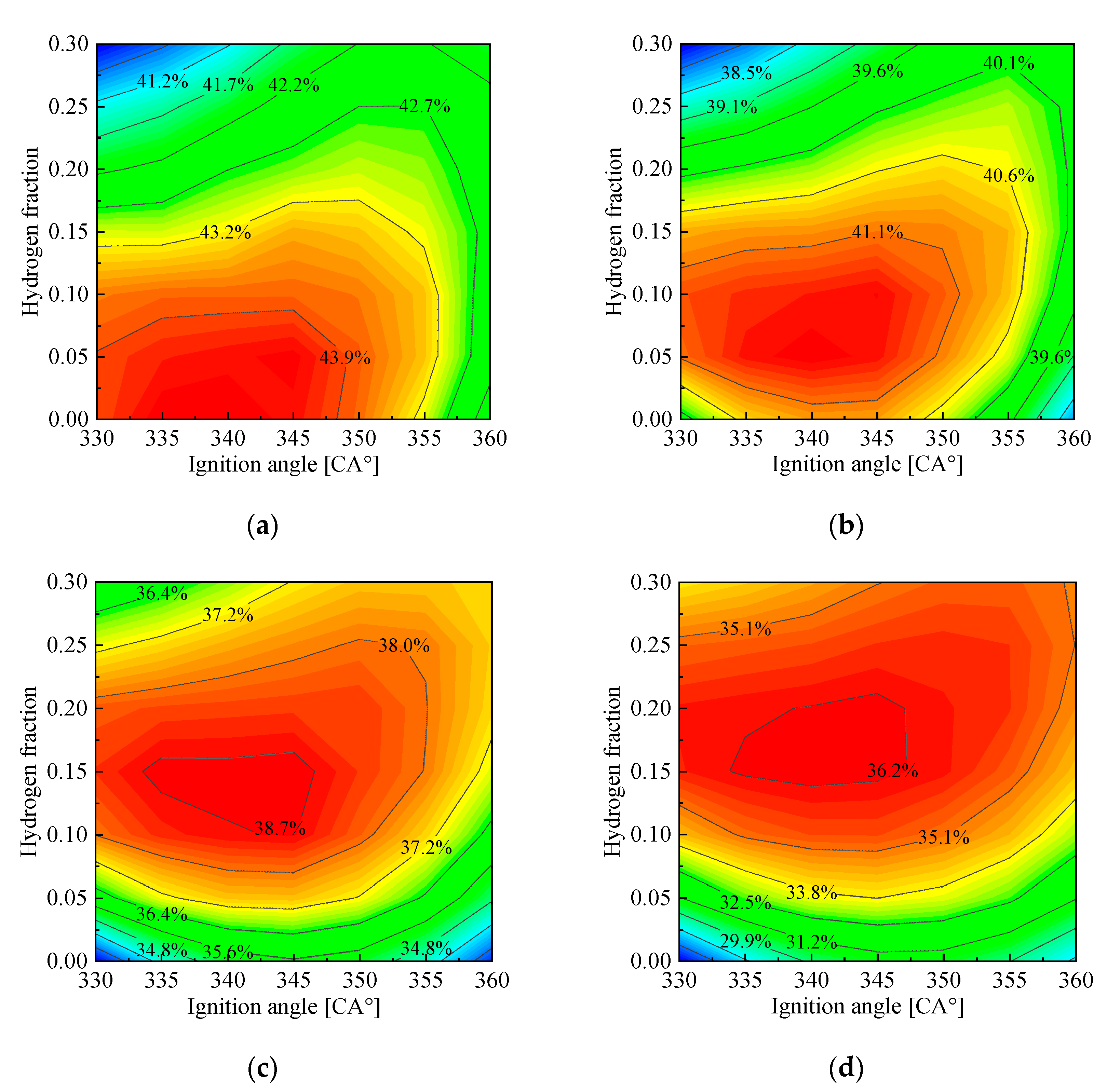
Figure 11 shows the effects of the ignition angle and hydrogen fraction on the indicated thermal efficiency at different altitudes. It can be seen from Figure 11a that although the increase in hydrogen brought about a larger heat release, the small ignition angle prevented the rapidly rising pressure from being effectively converted into mechanical energy. At an ignition angle of 330 [CA°], the indicated thermal efficiency decreased from 43.9% to 40.2%, with the hydrogen fraction increasing from 0 to 0.3. With the ignition delay, the indicated thermal efficiency increased briefly and then decreased under pure gasoline conditions, reaching the maximum of 44.2% at 340 [CA°]. The indicated thermal efficiency at a 0.3 hydrogen fraction increased continuously with the increase in the ignition angle. The indicated thermal efficiency at an ignition angle of 360 [CA°] was 42.0%, which was 4.5% higher than that at an ignition angle of 330 [CA°]; thus, the phenomenon of inefficient work was alleviated.
In Figure 11b–d, with the increase in altitude, the poor combustion caused by the low intake air density caused a significant drop in the indicated thermal efficiency. At an altitude of 6 [km], the indicated thermal efficiency under the design condition was 35.6%, 18.9% lower than that at an altitude of 0 [km]. This limitation can be compensated by increasing the hydrogen fraction. When the hydrogen fraction was increased to 0.2, the indicated thermal efficiency at an altitude of 6 [km] reached 0.36, 2.9% higher than that at a hydrogen fraction of 0.1. At high altitudes, the advantages of hydrogen doping began to manifest. On the one hand, the poor performance of the engine was improved under the condition of a small ignition angle and high hydrogen fraction. At an ignition angle of 330 [CA°] and a hydrogen fraction of 0.1, the indicated thermal efficiencies at altitudes of 0 [km], 2 [km], 4 [km], and 6 [km] were 91.3%, 94.0%, 110.8%, and 130.9% of those under pure gasoline conditions, respectively. On the other hand, as the altitude increased, the optimal indicated thermal efficiency moved toward the high hydrogen fraction conditions. The optimal thermal efficiencies at altitudes of 0 [km] and 6 [km] were 44.2% and 36.4% at an optimal hydrogen fraction of 0.0 and 0.15, respectively.
At high altitudes, compared to the hydrogen fraction, the ignition angle was less effective in optimizing the indicated thermal efficiency. At an altitude of 4–6 [km], an ignition angle between 340–345 [CA°] was favorable for the indicated thermal efficiency.
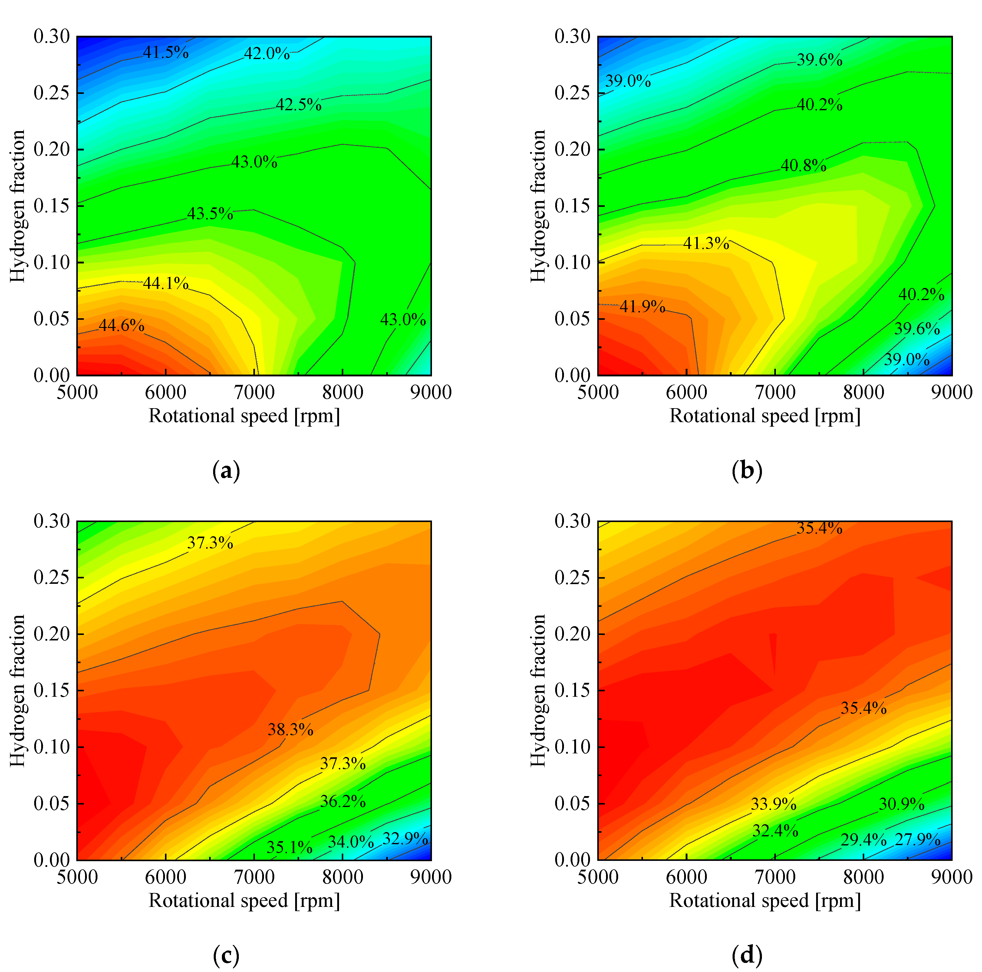
As shown in Figure 12, the interaction between the rotational speed and the hydrogen fraction and their effects on the indicated thermal efficiency were investigated. At an altitude of 0 [km], the low speed limited the power output and shortened the combustion duration angle, which was beneficial in improving the indicated thermal efficiency under pure gasoline conditions. The indicated thermal efficiency under the condition of 5000 [rpm] and a 0 hydrogen fraction was 45.1%, 10.3% higher than that at 5000 [rpm] and a 0.3 hydrogen fraction and 7.1% higher than that at 9000 [rpm] and a 0 hydrogen fraction, respectively.
At an altitude of 2 [km], with an increase in the rotational speed, the change in the indicated thermal efficiency as a result of the hydrogen fraction developed into a parabolic shape, and the hydrogen fraction corresponding to the optimal indicated thermal efficiency also increased accordingly. It is worth noting that the high rotational speed prolonged the combustion process of the engine, making it overlap with expansion. This was not conducive to the conversion of internal energy into mechanical energy and was exacerbated at high altitudes. Under the condition of 6 [km] altitude and 9000 [rpm], the indicated thermal efficiency under the pure gasoline condition was only 24.9%. Moreover, at high altitudes, the optimal thermal efficiency did not come about under a certain operating condition but under various operating conditions in terms of the combination of the rotational speed and hydrogen fraction. Thus, the adjustment of rotational speed and doped hydrogen becomes optional.

3.3.3. Indicated Specific Fuel Cost

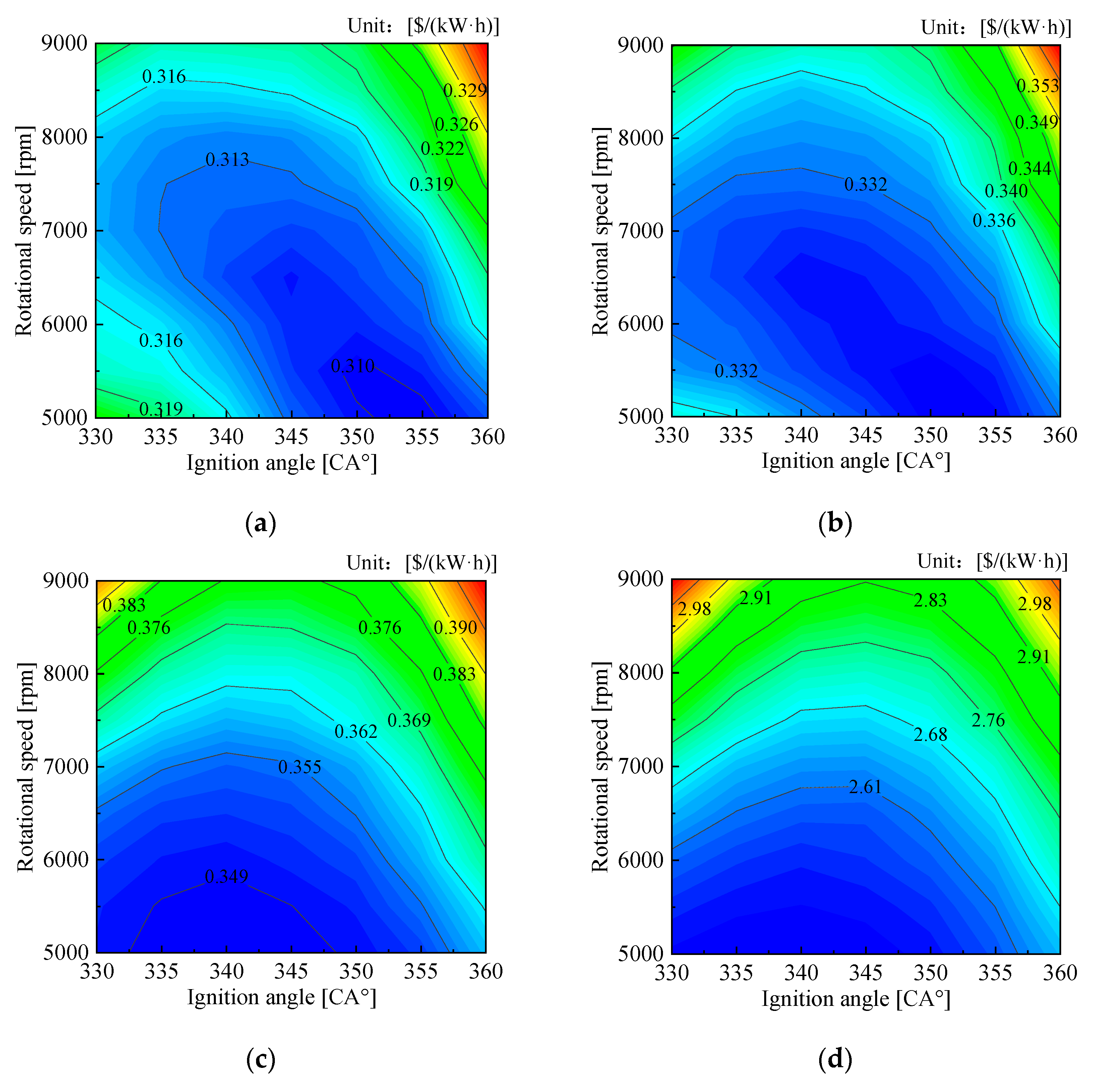
Figure 13 shows the effects of the ignition angle and rotational speed on the indicated specific fuel cost at different altitudes. Overall, there was a significant increase in the indicated specific fuel cost with increasing altitude. Under the design condition, the indicated specific fuel cost at an altitude of 6 [km] reached 0.384 [$/(kW·h)], 0.073 [$/(kW·h)] higher than that at an altitude of 0 [km]. In Figure 13a, low rotational speeds reduced the engine output power, while high rotational speeds increased the indicated power and fuel consumption, both of which increased the indicated specific fuel cost. As a result, at an ignition angle of 330 [CA°], the indicated specific fuel cost decreased and then increased with the increase in the rotational speed and reached the minimum of 0.314 [$/(kW·h)] at 7000 [rpm]. As the ignition angle increased, the optimal indicated specific fuel cost moved toward a lower rotational speed. When the ignition angle was 360 [CA°], the indicated specific fuel cost increased monotonically with increasing rotational speeds. The indicated specific fuel cost at 9000 [rpm] (0.336 [$/(kW·h)]) was 15.6% higher than that at 5000 [rpm].
As shown in Figure 13b–d, under high-altitude conditions, the energy conversion efficiency increased at a low rotational speed and small ignition angle and the indicated specific fuel cost improved. However, the indicated specific fuel cost at a high rotational speed remained at a high level. At an altitude of 6 [km], under the condition of an ignition angle of 330 [CA°] and rotational speed of 5000 [rpm], the indicated specific fuel cost was 0.372 [$/(kW·h)], increasing to 0.459 [$/(kW·h)] at 9000 [rpm]. In addition, the adjustment of the ignition angle became particularly important. An early or late ignition was not conducive to the economic performance of the engine. At an altitude of 6 [km], the optimal ignition angle of the engine was between 340–345 [CA°].

4. Conclusions

In this study, a single-zone homogenization model in high-altitude environments was established based on the novel HEHC rotary engine structure. Various factors, such as heat exchange, leakage, and physical properties, were comprehensively considered in the model. The indicated power, indicated thermal efficiency, and indicated specific fuel cost were selected to evaluate the engine’s power performance, energy conversion efficiency, and economic performance, respectively. The effects of altitude, hydrogen fraction, ignition angle, and rotational speed on the performance parameters were analyzed. The following conclusions were obtained:
(1)
At an altitude of 6 [km], the combustion duration angle under the pure gasoline condition was 92.0 [CA°], 88.5% higher than that at an altitude of 0 [km]. As the hydrogen fraction increased to 0.3, the combustion duration angle decreased to 26.5 [CA°], 28.8% of that at 6 [km]. In addition, a delayed ignition or low rotational speed were other methods that reduced the combustion duration angle.
(2)
With the increase in altitude from 0 [km] to 6 [km], the peak pressure dropped from 5.5 [MPa] to 2.7 [MPa]. This problem can be resolved by increasing the hydrogen fraction or decreasing the rotational speed. It is worth noting that at a hydrogen fraction of 0.3, the peak pressure of 6.6 [MPa] appeared at 365 [CA°], which was too late to be favorable for its conversion to mechanical energy.
(3)
Under the pure gasoline condition, the indicated thermal efficiency at an altitude of 6 [km] was only 20.3 [kW], 69.8% of that at an altitude of 0 [km]. The improvement effect of hydrogen was more pronounced with increasing altitude. At an altitude of 6 [km], the maximum indicated power, 33.6 [kW], appeared under a hydrogen fraction of 0.3 and a ignition angle of 345 [CA°].
(4)
The maximum thermal efficiencies at altitudes of 0 [km] and 6 [km] were 44.2% and 36.4% at an optimal hydrogen fraction of 0.0 and 0.15, respectively. In high-altitude environments, at a rotational speed of 7000 [rpm], an ignition angle of 340–345 [CA°] was beneficial to the indicated thermal efficiency.
(5)
Under the design condition, the indicated specific fuel cost at an altitude of 6 [km] reached 0.384 [$/(kW·h)], which was 0.073 [$/(kW·h)] higher than that at an altitude of 0 [km]. At an altitude of 6 [km], the indicated specific fuel cost was as low as 0.371 [$/(kW·h)] under the pure gasoline condition of an ignition angle of 340 [CA°] and a rotational speed of 5000 [rpm]. However, the indicated power was only 16.8 [kW], 69% of that under the design condition.

Author Contributions

Conceptualization, G.H.; data curation, Y.D. and Q.G.; investigation, X.G., H.E., and Y.L.; methodology, Z.Y.; writing—original draft, Z.Y.; writing—review and editing, Y.D. All authors have read and agreed to the published version of the manuscript.

Funding

This research was funded by the Science and Technology on Plasma Dynamics Laboratory Program, grant number No. 6142202210201.

Data Availability Statement

Not applicable.

Acknowledgments

We are grateful for the technical support provided by the Science and Technology on Plasma Dynamics Laboratory.

Conflicts of Interest

The authors declare no conflict of interest.

Nomenclature

Aarea [m2]Tin-cylinder temperature [K]
ATDCafter top dead centerT0initial temperature [K]
Bcylinder thickness [m]uinternal energy [J]
BTDCbefore top dead centervflame propagation speed [m·s−1]
cWiebe coefficientVvolume [m3]
CAcrackshaft angle [°]Vddisplacement [m3]
Cfindicated specific fuel cost [$·kW−1·h−1]Vpitcombustion chamber pit volume [m3]
Dhhydraulic diameter [m]Greek letters
eeccentric distance [m]φcrackshaft angle [CA°]
ISFCindicated specific fuel consumption [g·kW−1·h−1]φ0combustion start angle [CA°]
Kshape factorηthermal efficiency
mmass [kg]λthermal conductivity [W m−1·K−1]
mccombustion quality coefficientγspecific heat capacity [J/kg−1·K−1]
NuNusselt numberϕequivalence ratio
P0initial pressure [Pa]Subscripts
PrPrandtl numberbcombustion
Qquantity of heat [J]desdesign condition
rpmrevolutions per minuteend, r, cend cover, rotor, cylinder
Rgas constant [J·kg−1·K−1]f, l, exc, vfuel, leakage, exchange, vaporization
ReReynolds numbergas, hydgasoline, hydrogen
Rggenerating radius [m]in outintake, exhaust
Sengine strokesyssystem

References

  1. Zheng, X.; Fenzhu, J.; Shuiting, D.; Yunhai, Z.; Yu, Z.; Zhang, Q.; Farong, D. Effect of scavenge port angles on flow distribution and performance of swirl-loop scavenging in 2-stroke aircraft diesel engine. Chin. J. Aeronaut. 2021, 34, 105–117. [Google Scholar]
  2. Kuitche, M.A.J.; Botez, R.M. Modeling novel methodologies for unmanned aerial systems–Applications to the UAS-S4 Ehecatl and the UAS-S45 Bálaam. Chin. J. Aeronaut. 2019, 32, 58–77. [Google Scholar] [CrossRef]
  3. Mattarelli, E.; Rinaldini, C.A.; Wilksch, M. 2-stroke high speed diesel engines for light aircraft. SAE Int. J. Engines 2011, 4, 2338–2360. [Google Scholar] [CrossRef]
  4. Paredes, J.A.; Saito, C.; Abarca, M.; Cuellar, F. Study of effects of high-altitude environments on multicopter and fixed-wing UAVs' energy consumption and flight time. In Proceedings of the 13th IEEE Conference on Automation Science and Engineering (CASE), Xi’an, China, 20–23 August 2017; pp. 1645–1650. [Google Scholar]
  5. Meng, H.; Ji, C.; Yang, J.; Chang, K.; Xin, G.; Wang, S. A knock study of hydrogen-fueled Wankel rotary engine. Fuel 2022, 321, 124121. [Google Scholar] [CrossRef]
  6. Sadiq, G.A.; Al-Dadah, R.; Mahmoud, S. Development of rotary Wankel devices for hybrid automotive applications. Energy Convers. Manag. 2019, 202, 112159. [Google Scholar] [CrossRef]
  7. Ozcanli, M.; Bas, O.; Akar, M.A.; Yildizhan, S.; Serin, H. Recent studies on hydrogen usage in Wankel SI engine. Int. J. Hydrog. Energy 2018, 43, 18037–18045. [Google Scholar] [CrossRef]
  8. Zhang, Y.; Wang, W. Effects of leakage and friction on the miniaturization of a Wankel compressor. Front. Energy 2011, 5, 83–92. [Google Scholar] [CrossRef]
  9. Wang, W.; Zuo, Z.; Liu, J. Miniaturization limitations of rotary internal combustion engines. Energy Convers. Manag. 2016, 112, 101–114. [Google Scholar] [CrossRef]
  10. Ribau, J.; Silva, C.; Brito, F.P.; Martins, J. Analysis of four-stroke, Wankel, and microturbine based range extenders for electric vehicles. Energy Convers. Manag. 2012, 58, 120–133. [Google Scholar] [CrossRef]
  11. Meng, H.; Ji, C.; Yang, J.; Wang, S.; Xin, G.; Chang, K.; Wang, H. Experimentally investigating the asynchronous ignition on a hydrogen-fueled Wankel rotary engine. Fuel 2022, 312, 122988. [Google Scholar] [CrossRef]
  12. Finkelberg, L.; Kostuchenkov, A.; Zelentsov, A.; Minin, V. Improvement of combustion process of spark-ignited aviation wankel engine. Energies 2019, 12, 2292. [Google Scholar] [CrossRef]
  13. Shkolnik, A.; Shkolnik, N.; Scarcella, J.; Nickerson, M.; Kopache, A.; Becker, K.; Bergin, M.; Spitulnik, A.; Equiluz, R.; Fagan, R. Compact, lightweight, high efficiency rotary engine for generator, apu, and range-extended electric vehicles. In Proceedings of the NDIA Ground Vehicule Systems Engineering and Technology Symposium, Novi, MI, USA, 16–18 August 2018. [Google Scholar]
  14. Shkolnik, A.; Littera, D.; Nickerson, M.; Shkolnik, N.; Cho, K. Development of a Small Rotary SI/CI Combustion Engine; SAE Technical Paper: Warrendale, PA, USA, 2014. [Google Scholar]
  15. Littera, D.; Nickerson, M.; Kopache, A.; Machamada, G.; Sun, C.; Schramm, A.; Medeiros, N.; Becker, K.; Shkolnik, S.; Shkolnik, A. Development of the XMv3 High Efficiency Cycloidal Engine; SAE Technical Paper: Warrendale, PA, USA, 2015. [Google Scholar]
  16. Nickerson, M.; Kopache, A.; Shkolnik, A.; Becker, K.; Shkolnik, N.; Bergin, M.; Spitulnik, A.; Mikhailov, K.; Equiluz, R.; Fagan, R. Preliminary Development of a 30 kW Heavy Fueled Compression Ignition Rotary ‘X’Engine with Target 45% Brake Thermal Efficiency. In Proceedings of the WCX World Congress Experience, Detroit, MI, USA, 10–12 April 2018. [Google Scholar]
  17. Shkolnik, N.; Nickerson, M.; Littera, D.; Shkolnik, A. Progress in Development of a Small Rotary SI Engine. In Proceedings of the Conference on Propulsion Technologies for Unmanned Aerial Vehicles, Haifa, Israe, 16 February 2015. [Google Scholar]
  18. Perez, P.L.; Boehman, A.L. Performance of a single-cylinder diesel engine using oxygen-enriched intake air at simulated high-altitude conditions. Aerosp. Sci. Technol. 2010, 14, 83–94. [Google Scholar] [CrossRef]
  19. Wang, J.; Shen, L.; Bi, Y.; Lei, J. Modeling and optimization of a light-duty diesel engine at high altitude with a support vector machine and a genetic algorithm. Fuel 2021, 285, 119137. [Google Scholar] [CrossRef]
  20. Otchere, P.; Pan, J.; Fan, B.; Chen, W.; Lu, Y. Recent studies of fuels used in Wankel rotary engines. J. Energy Resour. Technol. 2021, 143, 030801. [Google Scholar] [CrossRef]
  21. Ji, C.; Meng, H.; Wang, S.; Wang, D.; Yang, J.; Shi, C.; Ma, Z. Realizing stratified mixtures distribution in a hydrogen-enriched gasoline Wankel engine by different compound intake methods. Energy Convers. Manag. 2020, 203, 112230. [Google Scholar] [CrossRef]
  22. Oh, S.; Park, C.; Nguyen, D.; Kim, S.; Kim, Y.; Choi, Y.; Lee, J. Investigation on the operable range and idle condition of hydrogen-fueled spark ignition engine for unmanned aerial vehicle (UAV). Energy 2021, 237, 121645. [Google Scholar] [CrossRef]
  23. Kaya, N.; Turan, Ö.; Midilli, A.; Karakoç, T.H. Exergetic sustainability improvement potentials of a hydrogen fuelled turbofan engine UAV by heating its fuel with exhaust gasses. Int. J. Hydrogen Energy 2016, 41, 8307–8322. [Google Scholar] [CrossRef]
  24. Su, T.; Ji, C.; Wang, S.; Cong, X.; Shi, L. Improving performance of a gasoline Wankel rotary by hydrogen enrichment at different conditions. Energy Convers. Manag. 2018, 171, 721–728. [Google Scholar] [CrossRef]
  25. Shi, C.; Ji, C.; Wang, S.; Yang, J.; Wang, H. Experimental and numerical study of combustion and emissions performance in a hydrogen-enriched Wankel engine at stoichiometric and lean operations. Fuel 2021, 291, 120181. [Google Scholar] [CrossRef]
  26. Amrouche, F.; Erickson, P.A.; Varnhagen, S.; Park, J.W. An experimental analysis of hydrogen enrichment on combustion characteristics of a gasoline Wankel engine at full load and lean burn regime. Int. J. Hydrogen Energy 2018, 43, 19250–19259. [Google Scholar] [CrossRef]
  27. Yang, J.; Ji, C.; Wang, S.; Wang, D.; Shi, C.; Ma, Z.; Zhang, B. Numerical study of hydrogen direct injection strategy on mixture formation and combustion process in a partially premixed gasoline Wankel rotary engine. Energy Convers. Manag. 2018, 176, 184–193. [Google Scholar] [CrossRef]
  28. Francesconi, M.; Antonelli, M. A numerical model for the prediction of the fluid dynamic and mechanical losses of a Wankel-type expansion device. Appl. Energy 2017, 205, 225–235. [Google Scholar] [CrossRef]
  29. Boretti, A. CAD/CFD/CAE Modelling of Wankel Engines for UAV; SAE Technical Paper: Warrendale, PA, USA, 2015. [Google Scholar]
  30. Kim, N.; Ko, I.; Min, K. Development of a zero-dimensional turbulence model for a spark ignition engine. Int. J. Engine Res. 2019, 20, 441–451. [Google Scholar] [CrossRef]
  31. Sui, C.; Song, E.; Stapersma, D.; Ding, Y. Mean value modelling of diesel engine combustion based on parameterized finite stage cylinder process. Ocean Eng. 2017, 136, 218–232. [Google Scholar] [CrossRef] [Green Version]
  32. Yasar, H.; Soyhan, H.S.; Walmsley, H.; Head, B.; Sorusbay, C. Double-Wiebe function: An approach for single-zone HCCI engine modeling. Appl. Therm. Eng. 2008, 28, 1284–1290. [Google Scholar] [CrossRef]
  33. Cho, J.; Song, S. Prediction of hydrogen-added combustion process in T-GDI engine using artificial neural network. Appl. Therm. Eng. 2020, 181, 115974. [Google Scholar] [CrossRef]
  34. Liu, J. Numerical Modeling and Simulation for Small-Scale Rotary Engine; Beijing Institute of Technology Press: Beijing, China, 2020; Volume 1, p. 269. [Google Scholar]
  35. Metghalchi, M.; Keck, J. Burning Velocities of Mixtures of Air with Methanol, Isooctane, and Indolene at High Pressure and Temperature. Combust. Flame 1982, 48, 191–210. [Google Scholar] [CrossRef]
  36. Costa, T.J.; Nickerson, M.; Littera, D.; Martins, J.; Shkolnik, A.; Shkolnik, N.; Brito, F. Measurement and Prediction of Heat Transfer Losses on the XMv3 Rotary Engine. SAE Int. J. Engines 2016, 9, 2368–2380. [Google Scholar] [CrossRef]
  37. Woschni, G. A universally applicable equation for the instantaneous heat transfer coefficient in the internal combustion engine. SAE Technical paper: Warrendale, PA, USA, 1967. [Google Scholar]
  38. Leboeuf, M.; Dufault, J.-F.; Nickerson, M.; Becker, K.; Kopache, A.; Shkolnik, N.; Shkolnik, A.; Picard, M. Performance of a Low-Blowby Sealing System for a High Efficiency Rotary Engine; SAE Technical Paper: Warrendale, PA, USA, 2018. [Google Scholar]
  39. Chen, W.; Pan, J.; Yang, W.; Liu, Y.; Fan, B.; Lu, Y.; Otchere, P. Stratified combustion characteristics analysis and assisted-ignition strategy optimization in a natural gas blended diesel Wankel engine. Fuel 2021, 292, 120192. [Google Scholar] [CrossRef]
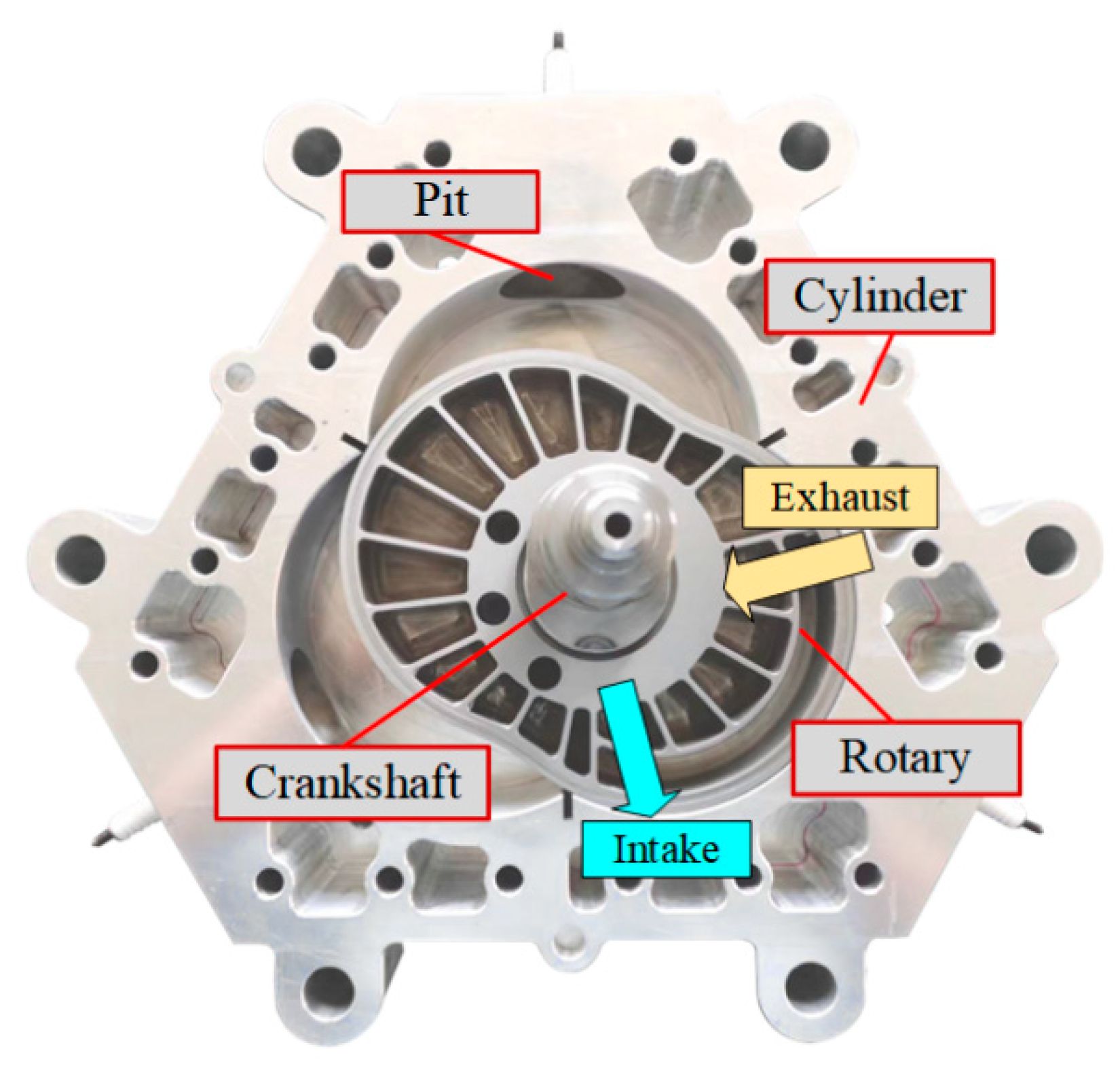
Figure 1. Structure of the HEHC rotary engine.
Energies 15 07948 g001
Figure 2. Schematic of the engine profile line. (a) Profile of cylinder; (b) profile of rotor.
Energies 15 07948 g002
Figure 3. Energy flow and mass flow of the system.
Energies 15 07948 g003
Figure 4. Flowchart of the single-zone model.
Energies 15 07948 g004
Figure 5. The pathways of heat exchange.
Energies 15 07948 g005
Figure 6. Relationship between leakage state, pressure, and phase angle.
Energies 15 07948 g006
Figure 7. Model verification of in-cylinder pressure. (a) Case 1: 9000 [rpm]; (b) case 2: 5000 [rpm].
Energies 15 07948 g007
Figure 8. Variations in combustion duration angles with different operating parameters. (a) Altitude–hydrogen fraction; (b) altitude–ignition angle; (c) altitude–rotational speed.
Energies 15 07948 g008
Figure 9. Variations in in-cylinder pressure with different operating parameters. (a) Altitude; (b) hydrogen fraction; (c) ignition angle; (d) rotational speed.
Energies 15 07948 g009
Figure 10. Effects of ignition angle and hydrogen fraction on indicated power at 7000 [rpm]. (a) Altitude: 0 [km]; (b) altitude: 2 [km]; (c) altitude: 4 [km]; (d) altitude: 6 [km].
Energies 15 07948 g010aEnergies 15 07948 g010b
Figure 11. Effects of ignition angle and hydrogen fraction on indicated thermal efficiency at 7000 [rpm]. (a) Altitude: 0 [km]; (b) altitude: 2 [km]; (c) altitude: 4 [km]; (d) altitude: 6 [km].
Energies 15 07948 g011
Figure 12. Effects of rotational speed and hydrogen fraction on indicated thermal efficiency at an ignition angle of 345 [CA°]. (a) Altitude: 0 [km]; (b) altitude: 2 [km]; (c) altitude: 4 [km]; (d) altitude: 6 [km].
Energies 15 07948 g012
Figure 13. Effects of ignition angle and hydrogen fraction on indicated specific fuel cost at a hydrogen fraction of 0.1. (a) Altitude: 0 [km]; (b) altitude: 2 [km]; (c) altitude: 4 [km]; (d) altitude: 6 [km].
Energies 15 07948 g013
Table 1. Structural characteristics of reciprocating, Wankel, and HEHC rotary engines.
TypeReciprocating EngineWankel EngineHEHC Rotary Engine
Two-StrokeFour-Stroke
Moving componentPistonTriangle rotor“8” shaped rotor
Kinematic pairCrank and rod mechanismPlanetary gear mechanism
CylinderBarrel cylinder“8” shaped cylinderTriangle cylinder
Crankshaft angle of per cycle [CA°]/cycle3607201080720
Number of chambers13
Stroke2464
Table 2. Profile equations of the cylinder and rotor.
Component Coordinate SystemProfile Equation
Rotor (epitrochoid)xr-or-yr x r = e cos ( δ ) + R g cos ( δ 3 ) y r = e sin ( δ ) + R g sin ( δ 3 )
Cylinder (outer envelope)x-o-y x = e cos ( ω ) + e cos ( δ ω 2 ) + R g cos ( δ 3 ω 2 ) y = e sin ( ω ) + e sin ( δ ω 2 ) + R g sin ( δ 3 ω 2 )
Table 3. Shape parameters and operating parameters of HEHC engine.
ParametersValue
TypeNaturally aspirated, air-cooled
FuelHydrogen, gasoline
Shape factor /K6.85
Eccentric distance/e13 [mm]
Cylinder thickness/B40.1 [mm]
Rotational speed/n7000 [rpm]
Displacement (single cylinder)/Vd235 [cm3]
Volume of pit (single cylinder)/Vpit26 [cm3]
Ignition angle15 [CA°] BTDC
Intake valve close angle135 [CA°] BTDC
Exhaust valve open angle162 [CA°] ATDC
Table 4. Leakage mass flow at different periods of system 1.
AeraAB
Object system (system 1)End stage of expansionCombustion
Adjacent system (system 2)Start period of intakeEnd period of exhaust
Psys_1/Psys_2 < ( 2 γ + 1 ) γ 1 γ > ( 2 γ + 1 ) γ 1 γ
Air leakage stateSubcriticalSupercritical
Leakage mass flow [dm/dφ]Subcritical: π 30 n P sys _ 1 A l 2 γ γ 1 M R T sys _ 1 [ ( P sys _ 2 P sys _ 1 ) 2 γ ( P sys _ 2 P sys _ 1 ) γ + 1 γ ]
Supercritical: π 30 nP sys _ 1 A l γ M R T sys _ 1 ( 2 γ + 1 ) γ + 1 γ 1
Table 5. Parameter selection of different cases.
AltitudeOperating ParametersObjective Parameter
Ignition AngleRotational SpeedHydrogen Fraction
Case 10~6 [km]330~360 [CA°]7000 [rpm]0~0.3Indicated power
Case 20~6 [km]330~360 [CA°]7000 [rpm]0~0.3Indicated thermal efficiency
Case 30~6 [km]345 [CA°]5000~9000 [rpm]0~0.3
Case 40~6 [km]330~360 [CA°]5000~9000 [rpm]0.1Specific fuel cost
Publisher’s Note: MDPI stays neutral with regard to jurisdictional claims in published maps and institutional affiliations.