Article

A Novel Hybrid Excitation Doubly Salient Generator with Separated Windings by PM Inserted in Stator Slot for HEVs

1
Department of Electrical Engineering and Automation, Harbin Institute of Technology, Harbin 150080, China
2
Harbin Electric Power Design Institute, State Grid Harbin Electric Power Supply Company, Harbin 150080, China
*
Author to whom correspondence should be addressed.
Energies 2022, 15(21), 7968; https://doi.org/10.3390/en15217968
Submission received: 26 September 2022 / Revised: 21 October 2022 / Accepted: 25 October 2022 / Published: 27 October 2022
(This article belongs to the Special Issue Advanced Permanent-Magnet Machines for Electric Vehicles)

Abstract

:
Aiming to design a generator with high reliability, high efficiency, and especially a constant output voltage over a wide speed range for hybrid electric vehicles (HEVs), this paper proposes a novel topology of a hybrid excitation doubly salient generator with separate windings (HEDSGSW). The topology herein utilizes a hybrid excitation type of PMs and DC windings to generate parallel magnetic circuits. In addition, PMs are embedded in the magnetic bridge to insulate the excitation windings with armature windings. This design can achieve compactness, efficiency, and especially constant output capability over a wide speed range. The geometry and flux regulation principles, including magnetic flux circuits, are elaborated. After comparing three power generation modes, the most suitable mode, namely, the doubly salient generation 2 (DSG2) mode, is confirmed to ensure a stable voltage output performance. Then, considering the non-uniformity effect of the stator and rotor slots, the no-load back electromotive force (EMF) expressions are derived based on the EMF to air-gap relative permeance method. Furthermore, a 1 kW HEDSGSW FEA model, with an output voltage of 42 V and a rated speed of 6000 rpm, is built to demonstrate the effectiveness of the proposed method. Finally, the operating properties of the HEDSGSW, such as no-load characteristics and adjustment characteristics, are analyzed to further verify the rationality of its magnetic flux circuit and the flexibility of the excitation regulation capability.

1. Introduction

Limited by their current battery life, power, and other key technologies, hybrid electric vehicles (HEVs), due to their advantages of low fuel consumption, low noise, sufficient momentum, etc., have gradually become a hot spot for research and development in recent years [1]. HEVs utilize a series power system consisting of a power battery unit and an auxiliary power supply unit (containing a combustion engine and a generator) [2]. As the kernel part of the battery charging system, constant output voltage capability over a wide speed range (e.g., 0.25–4 times the rated speed range) directly determines the operating efficiency of HEVs [3,4]. Therefore, determining how to design a generator for HEVs with high reliability, high power densities, and especially constant output performance is a challenge for researchers.
The original concept of doubly salient permanent magnet machines (DSPMMs) can be traced back to 1955, when they were named flux-switching machines and had PMs embedded in the stator [5]. This class of alternators has the inherent advantages of a simple structure, high efficiency, and especially excellent speed regulation performance over a wide speed range. However, the batch application was influenced by the limitations of PM demagnetization, the unignored tipple of output, and flexible flux regulation. With the advent of rare-earth permanent magnet (PM) materials, DSPMMs were then redeveloped in the early 1990s [6,7,8,9,10]. This class of DSPMMs has a structure similar to that of Variable Reluctance Motors (VRMs), except that PMs are buried in the stator core, stator slots, or in between the stator poles. The principle of installing PMs is to circumvent putting in the main magnetic circuit in order to avoid irreversible demagnetization. However, the irreconcilability of PM flux limits the application of DSPMMs, especially for high-speed operation. In particular, in the power generation state, there are difficulties in voltage regulation and demagnetization, while in the electric state, the ability of weakened magnetism is poor, and the speed range of constant power operation is narrow. For this reason, a doubly salient reluctance motor, which is essentially a doubly salient electrically excited machine (DSEM), was designed by Prof. Lipo’s group in early 1991 [11]. The researchers replaced the PMs with DC excitation windings to achieve a wide range of output voltages, fault protection, and flux regulation capability [12,13,14]. However, this topology inevitably requires a high-excitation EMF to achieve the required magnetic field intensity, hence degrading the power density and efficiency. Therefore, a hybrid excitation doubly salient generator (HEDSG) was proposed to maintain good flux regulation capability and wide-speed-range operation.
HEDSGs combine the advantages of DSPMMs and DSEMs by adopting the concept of installing PMs in the stator pole, core, or slots as a dual excitation source [15]. The idea of HEDSGs was first proposed by Prof. Lipo et al. in [16] and [17]. Excitation windings are placed in the stator slots, while PMs are embedded in the E-shaped stator yoke, forming a series magnetic circuit and increasing the reluctance of the main magnetic circuit. Although the operating speed range is wider, efficiency is sacrificed. Prof. Lipo et al. then designed an alternative topology to weaken the magnetic field using mechanical structures, such as short-circuit rings [18]. HEDSGs can inherently offer high power densities and a simple magnetic circuit, but this configuration needs relatively high excitation currents, resulting in low efficiency and the irreversible demagnetization of PMs. To solve the problem described above, an HEDSG with a special magnetic bridge was proposed in [19]. The researchers added a magnetic bridge under each PM to realize wider magnetic flux regulation, even with a small excitation current, thus naturally reducing the loss of electric excitation and improving efficiency. In addition, the literature [20] presented a novel DSPMM with a double-fed stator, essentially an HEDSG. This topology was designed with an additional magnetic barrier, that is, an additional air gap beside the PMs, which is equivalent to adding a parallel magnetic circuit to reduce the reluctance of the excitation circuit. To further improve the performance and reduce the cost of the machines, Prof. Zhu et al. designed a novel E-core flux-switching PM brushless AC machine [21]. The middle tooth of the E-shaped stator is no longer wound with the armature winding, and it also has no PMs embedded in the stator core. Compared with the traditional flux-switching PM motor, this topology reduced the volume of PMs and increased the area of stator slots, thus significantly cutting the cost and increasing the back EMF and electromagnetic torque by about 15%. In addition, to solve the problem of short circuits between excitation windings and armature windings, Prof. Hua et al. designed a hybrid-excited E-shaped flux-switching motor [22]. The excitation windings are located on spaced teeth of the E-shaped core without armature windings, thus providing physical isolation between phases, as well as magnetic isolation. To solve the problem of the irreversible demagnetization of PMs, a magnetic flux-switching type of HEDS reluctance motor with a parallel magnetic circuit was proposed, and it combined the principles of the switched reluctance machine (SRM) and the variable flux machine (VFM) [23,24,25]. By applying the concepts of using PMs as a dual excitation source, configuring PMs to avoid the main magnetic circuit, and using the PM flux to counteract the DC excitation flux, the torque density was determined, and the problem of the irreversible demagnetization of PMs was solved. Subsequently, based on this configuration of a 12/10 pole HEDSG, Prof. Zhu’s group systematically studied electromagnetic characteristics, PM eddy currents, and iron consumption and optimized the combination of stator and rotor poles [26]. However, the batch application of HEDSGs is influenced by their features or limitations: the complicated stator structure for processing, the risk of PM demagnetization, and the insulation of the field windings and armature windings in the stator slots. To date, there are still few systematic and general studies on the design, optimization, and control strategy of such HEDSGs.
Aiming to design a generator for HEVs with high reliability, high efficiency, and especially constant output over a wide speed range, the main contributions of this paper are twofold: First, a novel topology with a hybrid-parallel magnetic circuit and separate windings is proposed. Specifically, PMs are installed in the magnetic bridge to effectively separate the excitation windings from the stator windings, which not only results in a compact structure but also provides ideal insulation and facilitates flux control. The topology proposed herein is reliable and efficient, and it can also achieve a stable output voltage. The second contribution is the use of the air-gap relative permeance to the electromotive force (EMF) method to derive the no-load EMF expressions. The method is efficient and accurate, and it can provide a theoretical basis for analyzing operating performance, the initial design, and the optimization of such generators.
The remainder of this paper is organized as follows: Section 2 elaborates on the geometry, the magnetic flux path, and the flux regulation principle of the HEDSGSW. Section 3 compares three power generation modes. Section 4 utilizes an analytical model based on air-gap relative permeance to derive the expression of back EMF. Section 5 uses the FEA for model verification and further analyzes the working performance of the HEDSGSW. Finally, Section 5 concludes this paper.

2. Geometry and Flux Regulation Principle of the Proposed HEDSGSW
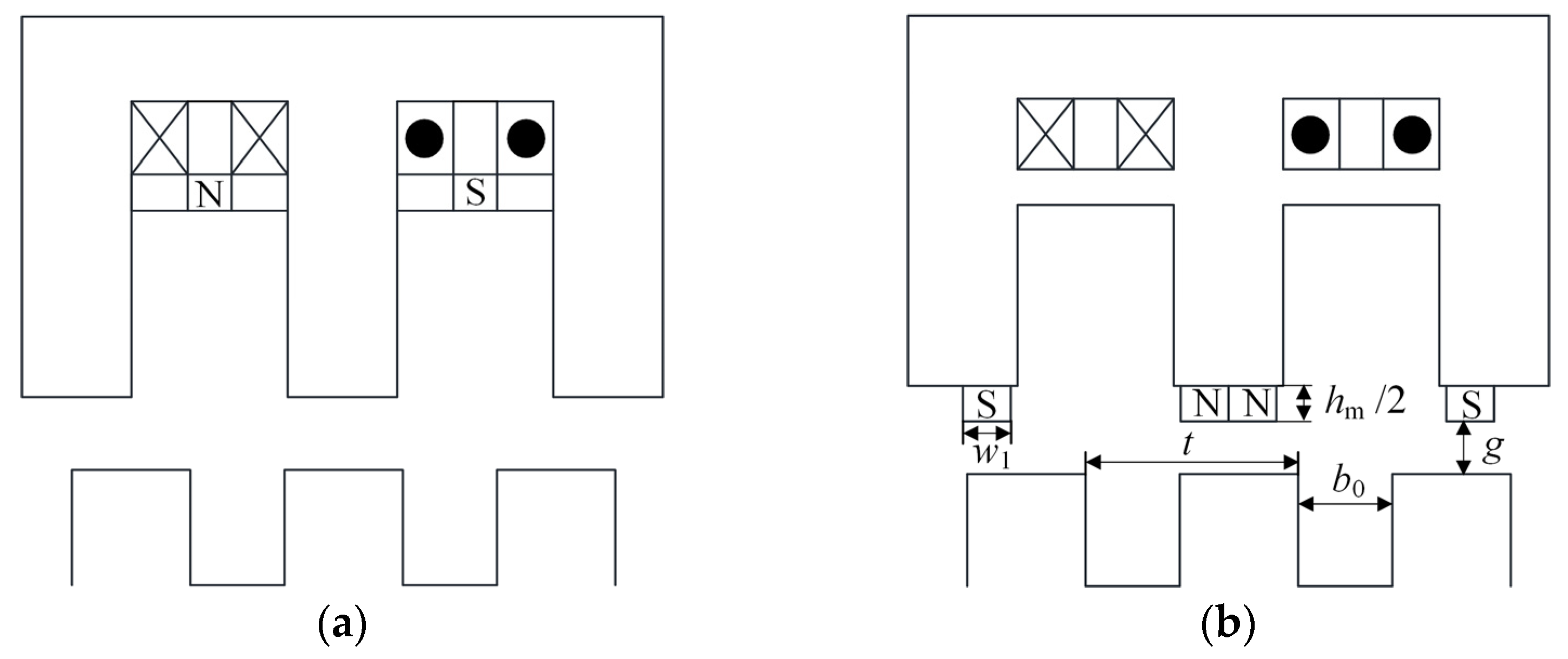
2.1. Geometry

Figure 1 depicts the geometry of the proposed HEDSGSW. The stator and rotor are both doubly salient types. The three-phase windings on the stator connect in a Y shape, and the windings on the two spatially opposite stator teeth connect in series. Moreover, no windings are on the rotor, which makes the structure simple and dependable. In addition, the excitation windings are installed in slot 1 (the inner slot), while the armature windings are installed in slot 2 (the outer slot). This layout separates these two windings in space, thereby providing better insulation. Moreover, PMs are embedded in the magnetic bridge between adjacent stator teeth, and the magnetization directions of the adjacent PMs are opposite. This arrangement makes the dimension optimization of PMs more flexible. Furthermore, the DC currents in the excitation windings flow in opposite directions, and they are arranged on adjacent teeth. The magnetic circuit in parallel results in small magnetic resistance. In general, the hybrid and parallel excitation approaches of PMs and DC excitation windings can achieve flux regulation, reduce excitation loss, and optimize efficiency. Compared with the configuration of [26], the pros of the proposed HEDSGSW are (1) insulation for the armature winding and DC winding; (2) less fringing flux that exists between the stator and the rotor poles; and (3) the flexible optimization of PMs, while the torque density is influenced by the slot filling rate due to the PM configuration, and the winding process is more complicated.

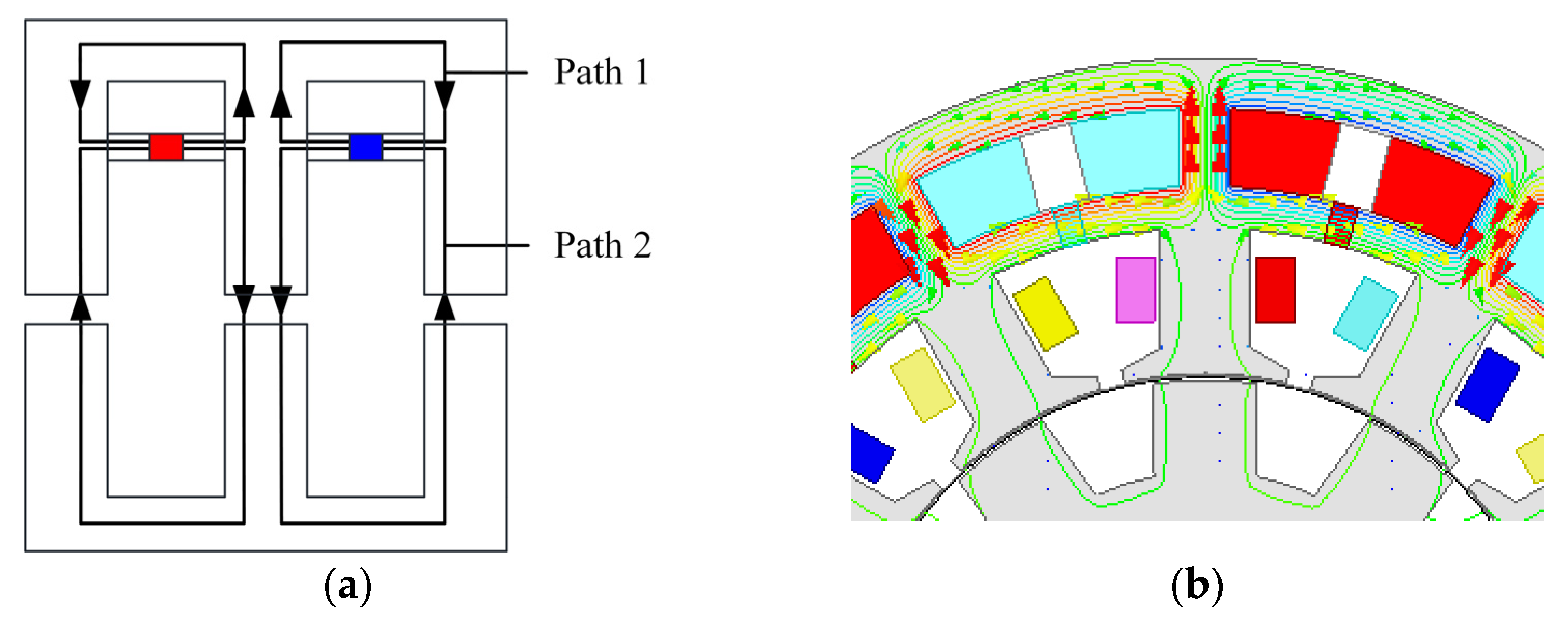
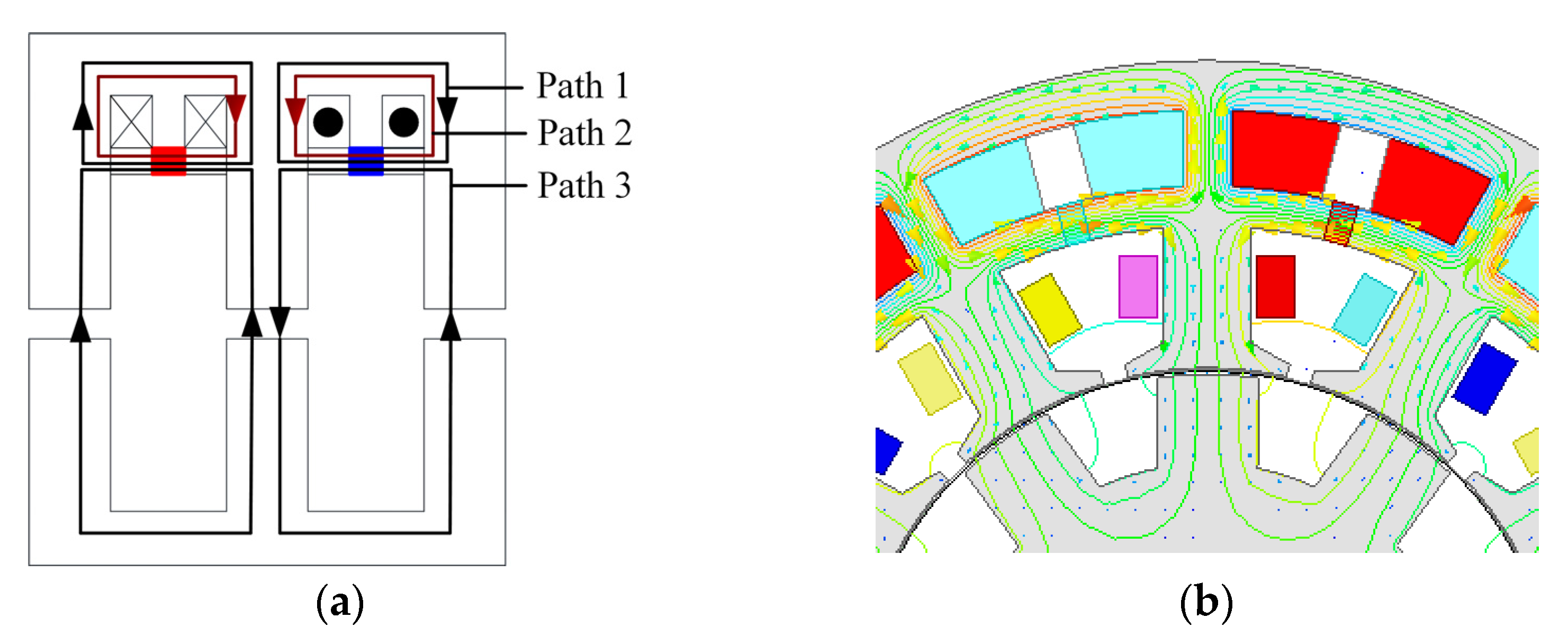
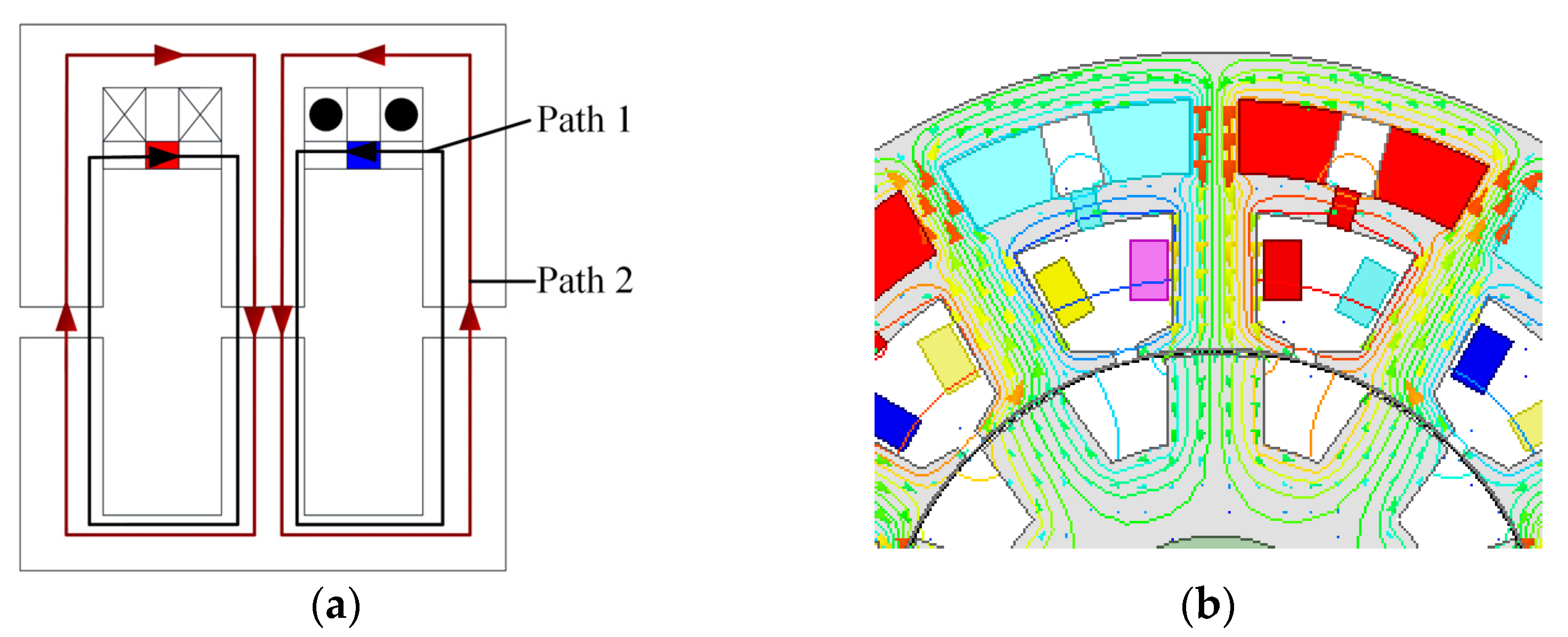
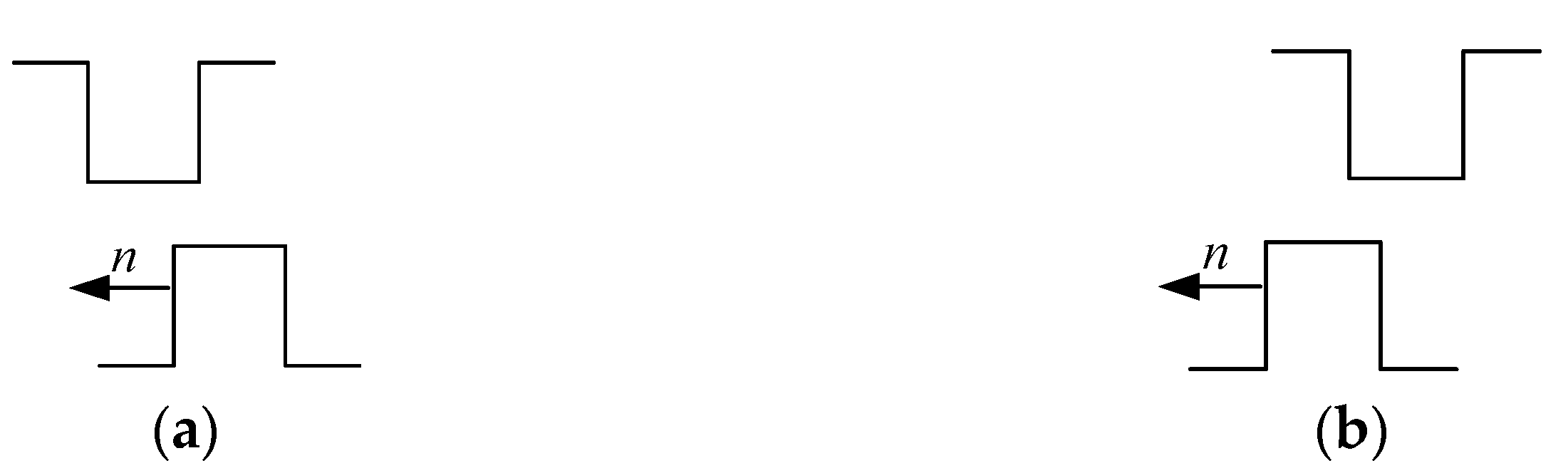
2.2. Magnetic Flux Regulation Principle

In this section, we adopt the approach of a theoretical analysis combined with FEA simulation verification to illustrate the magnetic flux regulation principle of the proposed HEDSGSW. The flux regulation principle of the proposed topology is similar to that of the reluctance generator abiding by the principle of the minimum reluctance path.
The proposed generator is configured with two excitation sources, i.e., an electric excitation source and a PM excitation source. The magnitude of the EMF will have a direct impact on the magnetic flux circuits. The magnetic flux path when only PM excitation is used is depicted in Figure 2a. At this point, the magnetic flux lines form the closed loops of path 1 and path 2. As path 2 passes through the air gap, the resistance of this path is relatively high, so the majority of flux lines form a closed loop of path 1, and only a small portion forms a closed loop of path 2, establishing the main magnetic field. The simulation result is shown in Figure 2b, and it is consistent with the preceding analysis.
Figure 3a illustrates the magnetic flux path generated by the excitation windings alone. The flux lines form the closed loops of path 1 and path 2. Herein, we assume that the PM permeability is similar to that of the vacuum, as the air-gap length is much smaller than the PM thickness. Thus, the majority of the flux lines generated by the excitation windings form a closed flux loop of path 2, while only a small portion of the flux lines form a closed loop through path 1, reducing the risk of PM demagnetization. The simulation results are shown in Figure 3b. Due to the tooth shoe, the distance between adjacent teeth is small, so some of the flux lines do not pass through the air gap but rather form a closed circuit through the tooth shoe.
When PM excitation and electric excitation are used in tandem, the situation becomes more complicated. As shown in Figure 2 and Figure 3 above, the flux lines of the two excitation sources flow in opposite directions in the stator yoke; hence, the magnitude of the adjustable excitation current determines the flux lines’ directions. Herein, the excitation current density is defined as the critical excitation current density Jf0 when the excitation current density is high enough to prevent the magnetic flux generated by the PMs from traveling through the stator yoke. Figure 4 depicts the magnetic flux path of hybrid excitation and the simulation results when Jf < Jf0. PM excitation generates the closed loops of paths 1 and 3, while electric excitation generates the closed loop of path 2. The magnetic flux generated by the PM gradually passes through path 3, forming a closed loop as the excitation current density increases. The flux paths of hybrid excitation when Jf < Jf0 are shown in Figure 5. Both the magnetic flux path 2 generated by the excitation current and the magnetic flux path 1 generated by the permanent magnets pass through the air gap to form a parallel magnetic circuit. Thus, the efficiency of the electrical excitation increases.

2.3. Overall Magnetic Flux Distribution

Herein, taking the case of Jf < Jf0 as an example, the overall magnetic flux distribution is demonstrated in terms of A-phase winding, as shown in Figure 6.
The 2-D FEA simulation results show that the armature windings with the same winding direction have a higher back EMF at the same excitation current density. In this case, the series winding of A1 and A2 can be equivalently regarded as a single winding, winding A. Then, the magnetic flux of winding A is equivalent to the magnetic flux of windings A1 and A2, and the same analysis can be carried out for windings A3 and A4. In Figure 6a, at a 0 electric angle, the magnetic flux of A2 is maximum, and the magnetic flux of A2 is zero, so the equivalent flux of winding A is the maximum. In Figure 6a, at a 0 electric angle, the magnetic flux of A2 is maximum, whereas the magnetic flux of A1 is nearly zero, so the magnetic flux of phase A winding is maximum. In Figure 6b, at a 90 electric angle, the total magnetic flux of A1 and A2 is exactly zero. In Figure 6c, at a 180 electric angle, the magnetic flux of A1 is almost zero, and the magnetic flux of A2 is maximum; hence, the magnetic flux of winding A is maximum. Finally, in Figure 6d, the total magnetic flux of A1 and A2 is exactly zero. Thus, the generator, by changing the rotor position, changes the reluctance of the magnetic flux circuit, which in turn changes the magnetic chain intersecting the stator winding, generating the back EMF.

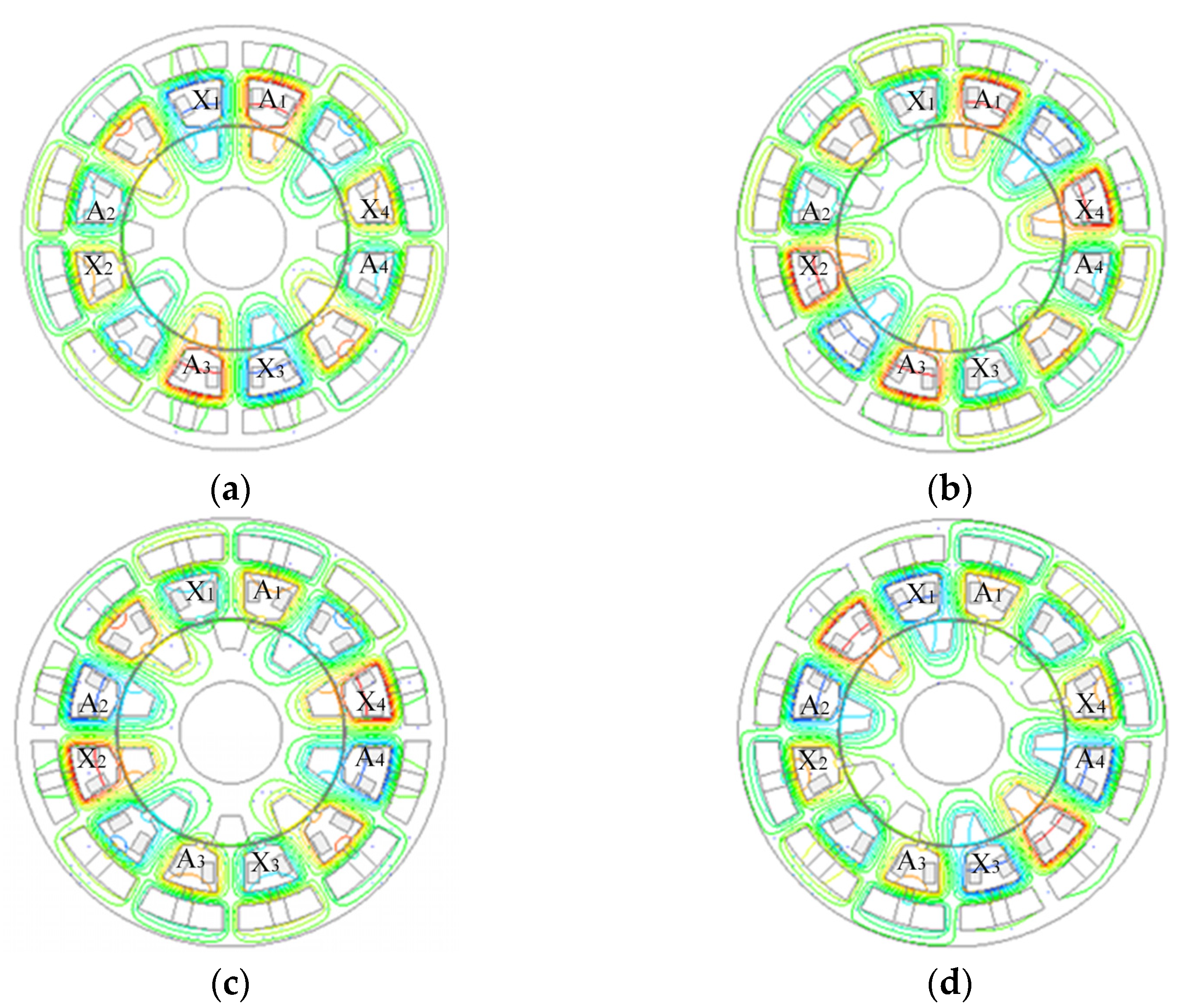
3. Analysis of Generation Mode

The generation mode determines the output performance of the generator. In this section, we theoretically analyzed the working principle of three generation modes, then built the three-phase bridge uncontrolled rectifier circuit using the FEA platform, and finally determined the most suitable generation mode with output voltage stability.
Traditional doubly salient generators often utilize three power generation modes based on the rotor position and rectifier unit connection: switched reluctance generation (SRG), doubly salient generation 1 (DSG1), and doubly salient generation 2 (DSG2) [27,28].
Herein, we introduced the concepts of the slip-in and slip-out processes to clearly describe the relative position relationship between the rotor tooth and the stator tooth when the rotor rotates. The slip-in process of the rotor, as shown in Figure 7a, refers to the process by which, as the rotor rotates, the rotor tooth gradually approaches the stator tooth, and the overlap between the two increases until the maximum value is reached. The slip-out process of the rotor is shown in Figure 7b. When the rotor rotates, the rotor teeth gradually move away from the stator teeth, and the overlapping portion of the two shrinks until it reaches the minimum value.

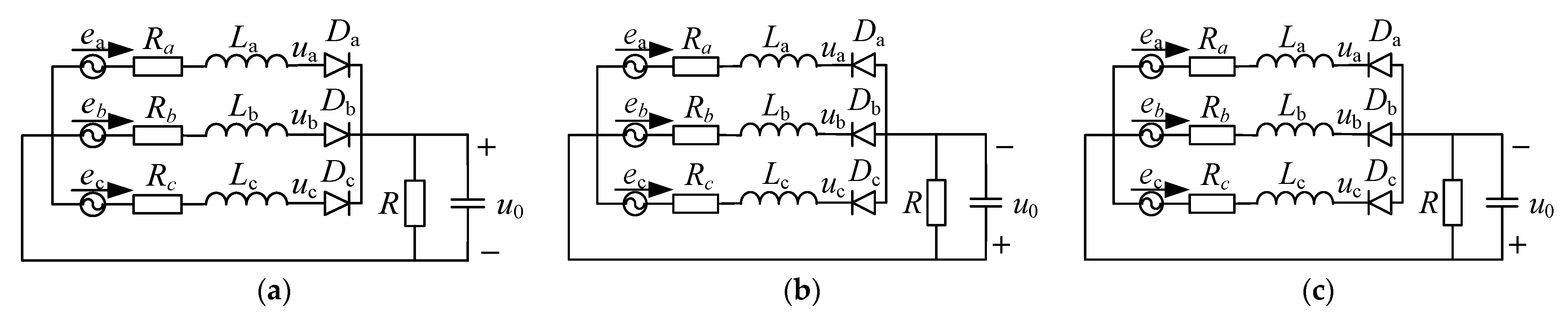
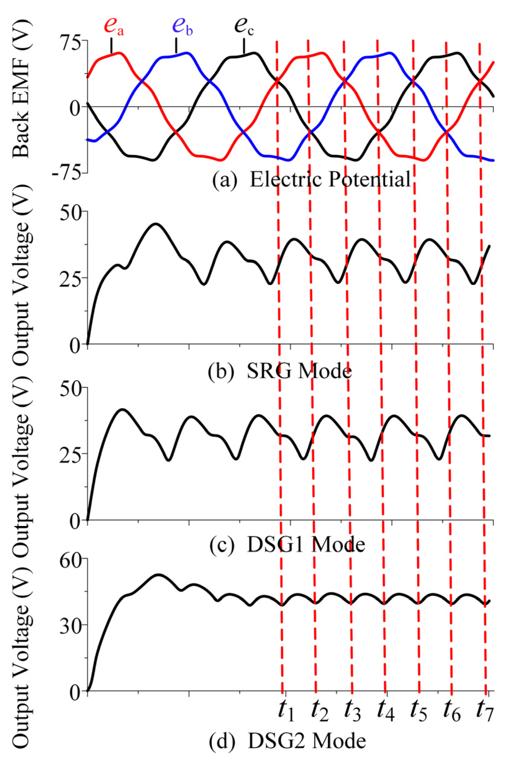
3.1. Principle of Three Generating Modes

The rectification circuits of the three generation methods, as depictured in Figure 8, are analyzed and explained below.
In terms of the SRG mode in Figure 8a, diodes are utilized as uncontrolled rectifiers. The diodes employ the common anode connection; that is, their cathodes are connected to the corresponding ends of the armature winding. Half-wave rectification produces DC, and capacitance then filters the voltage after rectification. When the rotor pole slips out of the stator pole, the flux linkage of the cross-link with the armature winding decreases. According to the Lenz law, the armature current will prevent the flux linkage from being reduced, so the armature current has the effect of magnetic enhancement at this time. Without taking internal resistance into account, the output voltage of SRG is shown as follows:
u 0 = max ( u a , u b , u c ) U D
where ua, ub, and uc are the three-phase voltages of a, b, and c, respectively, and UD is the voltage drop of the rectifier diode.
Then, in Figure 8b portraying the DSG1 mode, which is different from the SRG mode, the diodes employ a common cathode connection. When the rotor pole slides into the stator pole, the flux linkage interconnected with the armature winding increases. As is well-known, the armature current always obstructs this increasing trend, that is, the increase in the flux linkage, so the armature current has a demagnetizing effect at this time. If the influence of internal resistance is ignored, the output voltage of DSG1 is as follows:
u 0 = min ( u a , u b , u c ) U D
The DSG2 mode is depicted in Figure 8c. This mode is a hybrid of the SRG and the DSG1 modes. It uses a full-bridge circuit with six rectifier diodes to generate electricity as the rotor moves in and out. As a result, it possesses the properties of the first two power generation methods, namely, armature. When the rotor slips out, the current magnetizes, and when the rotor slips in, the current demagnetizes. If the influence of internal resistance is ignored, the output voltage of DSG2 is as follows:
u 0 = max ( u a , u b , u c ) min ( u a , u b , u c ) 2 U D

3.2. Comparison of Three Generation Modes

A three-phase bridge rectifier circuit model is built using finite element software. The external circuit is connected in series with a resistive load, while the DC side is connected in parallel with a filter capacitor. The output voltage waveforms of the HEDSGSW are compared under three power generation modes. The output voltage performances of the three generation modes are depicted in Figure 9, with (a), (b), and (c) showing the SRG, DSG1, and DSG2 output voltages curves, respectively.
In Figure 9a, the output voltage fluctuates 3 times in one cycle. Due to the higher voltage regulation of the generator at the rated load, the resulting output voltage is reduced compared to the no-load back EMF. The amplitude of the back EMF of phase a is greatest during t1 to t3, and the output voltage is the phase a voltage. Similarly, the output voltage is the phase b voltage from t3 to t5, and then the phase c voltage is from t5 to t7. Note that, in the SRG mode, the waveform of the output voltage leads the waveform of the back EMF by a certain angle because the armature current has a magnetizing effect with a load.
Similarly, with the SRG mode, the output voltage of DSG1 also fluctuates 3 times in one cycle, as shown in Figure 9b. The difference is that, during t2 to t4, the amplitude of the back EMF of phase c is the smallest, and the output voltage is the voltage of phase c. Then, from t4 to t6, the back EMF of phase a is the smallest, and the output voltage is the voltage of phase a. The armature current has a demagnetization effect in this power generation mode, causing the output voltage to lag behind the no-load back EMF by a certain angle.
In Figure 9c, the output voltage fluctuates 6 points in one cycle. The amplitude of the back EMF of phase a is the greatest during t1 to t2, the amplitude of the back EMF of phase b is the smallest, and the output voltage is uab. Then, from t2 to t3, the amplitude of the back EMF of phase a is the greatest, while that of phase c is the smallest, and the output voltage is uac. Next, during t3 to t4, the greatest amplitude of the back EMF is phase b, while the smallest is phase c, and the output voltage is ubc. In the following period, t4 to t5, t5 to t6, and t6 to t7, the greatest amplitudes of the back EMF are phase b, phase c, and phase c, while the smallest amplitudes of the back EMF are phase a, phase a, and phase b, respectively. The output voltage is uba, uca, and ucb. In conclusion, in the DSG2 mode, the armature current has different effects at different positions of the rotor; that is, it has a demagnetization effect when the rotor slides in and a magnetization effect when the rotor slides out. The angles by which the output voltage leads and lags cancel each other out so that the phase of the output voltage is the same as that of the no-load back EMF. In addition, the output voltage is more stable at this time, and the fluctuation is smaller compared with the two previous power generation methods.
Figure 9 also illustrates that the output voltages of the SRG and DSG1 modes are essentially the same, with an average value of about 32 V. The armature reaction is the primary cause of this phenomenon. The rectified output voltage of the DSG2 mode is higher, which causes the armature current to increase, eventually resulting in a decrease in the output voltage. DSG2 has the highest efficiency and output voltage in terms of efficiency. Based on the above comparative analysis, it was finally determined to use the power generation method of DSG2 for the proposed generator.

4. Analytical Model of Back EMF

Figure 10a shows one pair of poles for the stator structure. It is not possible to specifically determine the flux paths generated by the permanent magnets to establish the analytical expressions of the PM potential. Therefore, referring to the permanent magnet equivalence method in References [29,30], we equate the single permanent magnet between the stator teeth to two sub-permanent magnets, which are placed at the end of the stator teeth, and the equivalent structure is shown in Figure 10b. It should be noted that the magnetic field strength of the air gap before and after the equivalence is equal.
In Figure 10a from the previous analysis, it can be seen that the magnetic flux generated by the PMs does not form a closed loop through the air gap. The structure in Figure 10a indicates that only part of the MF of the PMs acts on the air-gap magnetic field, while the structure in Figure 10b indicates that the magneto-motive forces of the PMs all act on the air-gap magnetic field. The corresponding relationship between these structures can be equal.
The following assumptions need to be made when deriving the back EMF expressions:
  • Core saturation is ignored;
  • End effects and edge effects are ignored;
  • The air-gap magnetic field changes along the tangential direction and remains unchanged along the radial direction.

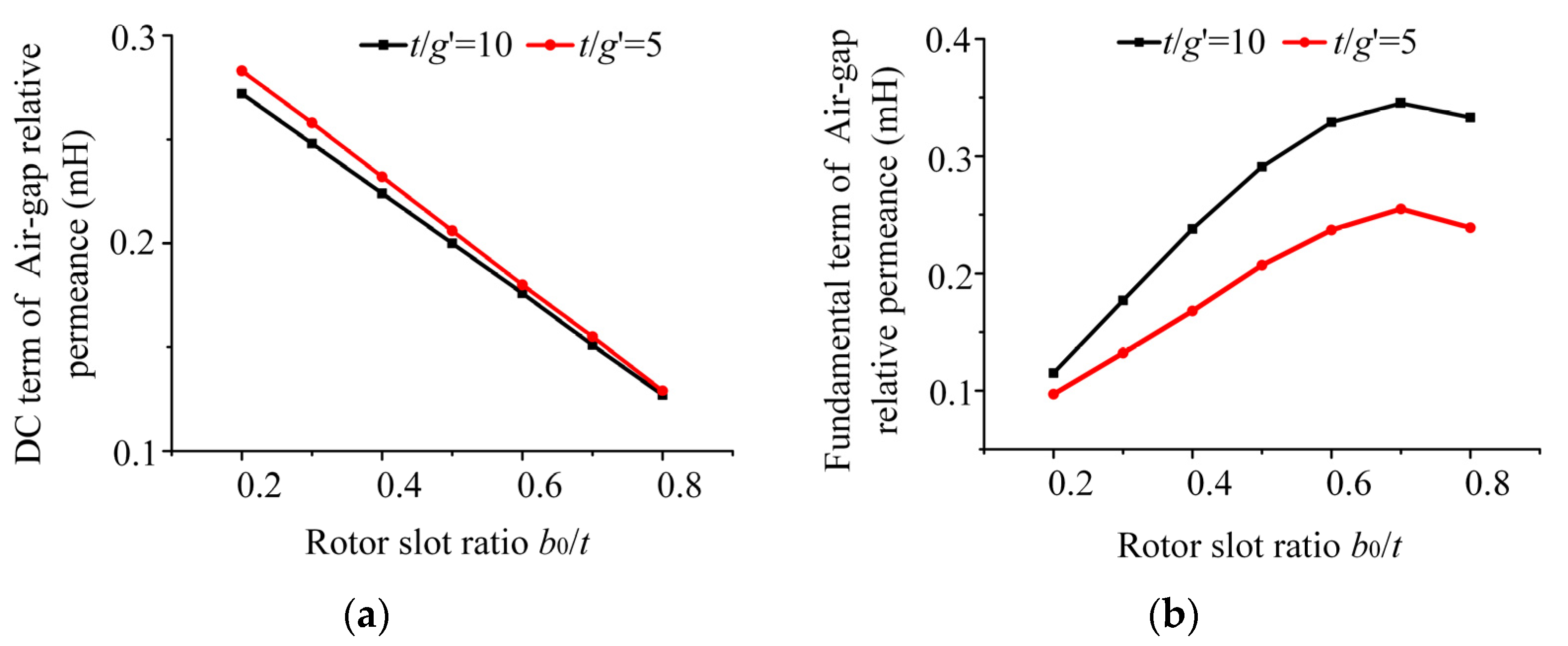
4.1. Relative Magnetic Permeance of Air Gap

Before the analysis, we first introduced the notion of air-gap relative permeance, i.e., the air-gap permeance per unit area, to characterize the non-uniformity of the air-gap permeance due to the slotting of the stator [31,32,33]. In the calculation below, this is represented by the symbol λ.
Without considering the excitation magnetic field, the no-load flux density in the air gap B(θs) can be calculated using (4):
B ( θ s , θ ) = F PM ( θ s ) λ ( θ s , θ )
where θs represents the angle between the axis of the A-phase winding and a certain position of the stator; θ is the angle between the axis of the A-phase winding and the axis of the rotor.
For an ideal salient-pole generator, when only the constant and fundamental components are considered, the air-gap permeance per unit area is calculated as follows:
λ ( θ s , θ ) = λ 0 + λ 1 cos [ Z r ( θ s θ ) ]
where λ0 is the constant or DC term of the air-gap relative permeance; λ1 is the fundamental term of the air-gap relative permeance; and Zr is the number of rotor slots.

4.2. Magnetic Potential

The MF of the HEDSG consists of two parts, one is generated by the PM, which can be calculated using (6), and the other is generated by the electric excitation, which can be calculated using (7).
F c = H c h m / 2 = B r μ 0 μ r h m / 2
F f = N f I f
where Br is the magnetic remanence of the PMs; Hc is the coercivity; hm is the thickness of the PMs; μr is the relative permeability; Nf is the number of turns of the excitation winding; If is the excitation current.
According to Figure 10b, the magnetizing directions of the PMs on adjacent teeth of the generator stator are opposite, so the N and S directions of the PMs are arranged in sequence, and a pair of N and S PMs form a complete period 2π. There are Zs/2 periods in total, and one period is 4π/Zs, so the MF of PM FPM(θs) is a periodic function with a period of 4π/Zs. The expression of MF in the PMs is given below:
F PM ( θ s ) = F c 0 θ s < 4 π S 0 / Z s 0 4 π S 0 / Z s θ s < 2 π / Z s F c 2 π / Z s θ s < ( 1 + 2 S 0 ) 2 π / Z s 0 ( 1 + 2 S 0 ) 2 π / Z s θ s < 4 π / Z s
where Zs is the number of stator slots, and S0 is the ratio of PM width to stator slot pitch.
F PM ( θ s ) = a 0 2 + n = 1 [ a n cos ( n Z s 2 θ s ) + b n sin ( n Z s 2 θ s ) ]
a n = 0
b n = F c n π [ 1 + ( 1 ) n + 1 ] [ 1 cos ( 2 S 0 n π ) ]
As the rotor is slotted, the coefficients of the air-gap relative permeance can be obtained using conformal transformation:
λ 0 = μ 0 g ( 1 1.6 β b 0 t )
λ 1 = 4 μ 0 β π g [ 0.5 + ( b 0 / t ) 2 0.78125 2 ( b 0 / t ) 2 ] sin ( 1.6 π b 0 / t )
g = g + h m 2 μ r
β = 0.5 1 2 1 + ( b 0 2 t t g ) 2
where g, g′, b0, and t are the air-gap length, the equivalent air-gap length, the rotor slot width, and the rotor slot pitch, respectively.

4.3. Magnetic Flux Density and Back EMF

Then, the flux density in the air gap is determined through the PM potential of (9) and the relative permeance of (12) and (13), as shown in the following:
B ( θ s , θ ) = λ 0 + λ 1 cos [ Z r ( θ s θ ) ] n = 1 b n sin ( n Z s 2 θ s )
Since the DC component of the relative permeance does not generate the counter-EMF, the air-gap tour can also be simplified as follows:
B ( θ s , θ ) = n = 1 λ 1 b n 2 sin [ ( n Z s 2 + Z r ) θ s Z r θ ] + sin [ ( n Z s 2 Z r ) θ s + Z r θ ]
The flux linkage of the stator winding can be calculated as follows:
ψ ph ( θ ) = r si l ef 0 2 π N ( θ s ) B ( θ s , θ ) d θ s
where rsi and lef are the stator inner radius and lamination length, respectively. N(θs) represents the A-phase winding function.
N ( θ s ) = i = 1 N i cos ( i P θ s )
Moreover, Ni is the winding function of the i-th harmonic:
N i = 2 i π N s P k wi
where Ns is the number of series turns per phase winding, and P is the number of the stator winding pole pairs. kwi is the winding coefficient of the i-th harmonic, which can be calculated with the following (22) short-pitch coefficient and (23) distribution coefficient:
k wi = k p i k d i
k pi = sin ( i y 1 τ π 2 )
k di = sin ( i π 2 m ) / q 2 sin ( i α 2 )
τ = Q 2 p
α = p 360 Q
where y1, τ, α, q, and Q are the pitch of the coil, the winding pole distance, the electric angle between the EMF of adjacent slots, the number of slots per phase of the generator, and the number of stator slots, respectively. When calculating the generator flux linkage (see (18)), since the integral interval of the function is on the circumference of the inner diameter of the stator, the integral of the sine function is not zero only when the coefficient before the θs variable is zero. Therefore, if the generator can generate back EMF, the number of stator winding pole pairs and the number of stator and rotor slots should satisfy the following constraint:
P = i Z s / 2 ± Z r i = 1 ,   3 ,   5
Then, we finally obtain the generator flux linkage equation:
ψ ph ( θ ) = N s r si l ef i = 1 λ 1 b i ( k w n n k w m m ) sin ( Z r θ )
n = i Z s / 2 Z r P i = 1 ,   3 ,   5 m = i Z s / 2 + Z r P i = 1 ,   3 ,   5
where kwn and kwm are the winding coefficients of the n-th and m-th harmonics, respectively.
Differentiating the flux linkage of (27), we can obtain the expression for the phase back EMF:
E ph ( θ ) = d d t [ ψ ph ( θ ) ]
E ph ( θ ) = ω m Z r N s r si l ef / P n = 1 λ 1 b n ( k w m m k w n n ) sin ( Z r ω m t )
where ωm is the mechanical angular velocity of the rotor.
Through the previous magnetic circuit analysis, it can be seen that phase back EMF is proportional to the excitation MF. It is finally simplified as
E ( θ ) = E ph ( θ ) F f / F c

5. Model Evaluation and Working Performance Analysis

5.1. FEA Verification

To verify the correctness of the analytical model of the back EMF in the previous section, a 1 kW HEDSGSW FEA model, with an output voltage of 42 V and a rated speed of 6000 rpm, was built as an illustrated example. The parameters of the studied HEDSGSW are shown in Table 1.
The results illustrated in Figure 11a clearly show that, as the rotor slot ratio increases, the magnitude of the back EMF first increases and then decreases, and it reaches the maximum value when the slot ratio is about 0.7. Based on the curves, it can be seen that the trend of the analytical model and the FEA results is the same, but there is a certain amount of difference between them. Figure 11b illustrates the variations in the back EMF with an excitation current. When the excitation current is low, the analytical solution corresponds well with the FEA results. However, when the excitation current is large, due to the saturation of the magnetic circuit of the generator, the back EMF amplitude of the FEA solution does not increase, while the analytical solution still increases linearly because the magnetic circuit saturation is not considered. In this case, the analytical model has a large deviation.

5.2. Air-Gap Relative Permeance Analysis

From Equations (12)–(15), it is clear that the air-gap relative permeance is related to the three coefficients, namely, the rotor slot distance to effective air-gap length ratio t/g’, the rotor slot occupation ratio b0/t, and the effective length of the air gap g′. When g′ decreases, the values of the constant term λ0 and the fundamental term λ1 increase. However, g′ cannot be infinitely small due to factors of mechanical reliability, harmonics, and losses of the generator.
Figure 12 shows the variation in the air-gap relative permeance with the rotor slot ratio. As illustrated in Figure 12a, with an increase in the rotor slot ratio, the DC term of the air-gap relative permeance decreases inversely. This is mainly because, when increasing the rotor slot ratio, the air-gap magnetic permeance becomes much smaller than that of the silicon steel sheet, which is equivalent to increasing the effective length of the air gap, resulting in a decrease in the DC term of the relative permeance. In addition, when the effective length of the air gap is constant, the variation in t/g’ has a minor effect on the DC term of the air-gap relative permeance. It can also be seen from Equation (15) that t/g′ has little effect on the value of the coefficient β. As shown in Figure 12b, with an increase in the rotor slot ratio, the fundamental term of the relative permeance first increases and then decreases. The slot ratio reaches a maximum value when the ratio of the slots is around 0.7, and when t/g′ increases, the curve moves up.

5.3. Working Performance Analysis

To further illustrate the rationality of the magnetic flux circuits and the flexibility of the excitation regulation capability of HEDSGSW, in this section, we focus on analyzing the working performance, i.e., the no-load characteristics and adjustment characteristics.

5.3.1. No-Load Characteristic

The no-load characteristic (i.e., U = f (If)) refers to the relationship between the load terminal voltage U and the excitation current If when working at the rated speed n and when the load current Ia is zero. Whether the magnetic circuit design of the machine is reasonable and accurate can be determined using this characteristic.
For a wide speed range analysis of the actual condition of the generator, the simulation speeds are set as 1500 rpm, 6000 rpm, and 12,000 rpm. The value of the excitation current is adjusted at the same speed to obtain the no-load back EMF amplitude, and a no-load characteristic diagram is obtained, as shown in Figure 13. This diagram shows that, when the excitation current is small, the no-load characteristic curve is a straight line. This is because the stator and rotor cores of the generator are not saturated under this working condition, and the core reluctance can be ignored, so the magnetic flux is proportional to the excitation current, and the no-load back EMF is linearly related to the excitation current. As the excitation current gradually increases, the no-load characteristic curve reaches the peak and then gradually declines. This is due to the increase in the magnetic flux on the stator and rotor teeth; the iron core becomes gradually saturated, and the no-load back EMF amplitude therefore peaks. At the same time, with the deepening of the saturation degree, the reluctance on the stator and rotor teeth increases, causing the no-load back EMF amplitude to start to decrease after the peak. Note that, as the rotational speed increases, the magnitude of the back EMF decreases faster. A possible explanation for this trend is as follows: when the generator operates at high speed, the stator and rotor teeth are more saturated, resulting in a greater reluctance of the magnetic circuit, which leads to an increase in the EMF drop on the stator and rotor teeth.

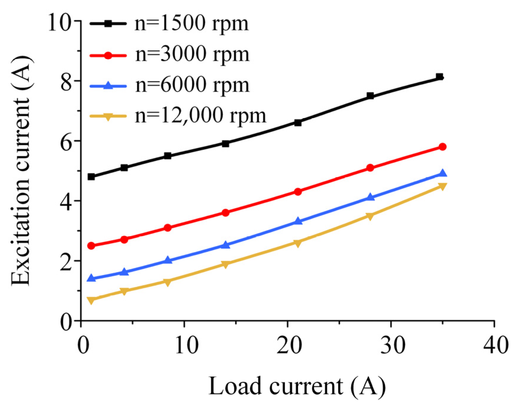
5.3.2. Adjustment Characteristic

The adjustment characteristic (i.e., If = f (Ia)) refers to the relationship between the load current Ia and the excitation current If when the generator works at the rated speed n and when the output voltage U and the load power factor cosϕ are constant. This characteristic reflects the adjustment ability of the excitation current to keep the output voltage constant when the load varies.
The relationship between the load currents and excitation currents was determined when the generator was operating in the DSG2 mode with an output voltage of 42 V and a constant speed.
As shown in Figure 14 there is a clear increasing trend between the excitation current and the load current. The load current is set from 1 to 35 A. When the speed is 1500 rpm, the excitation current ranges from 4.8 A to 8.1 A. When the speed is 3000 rpm, the excitation current range is reduced from 2.5 A to 5.8 A. As the speed increases up to 6000 rpm, the excitation current is reduced from 1.4 A to 4.9 A. When the speed is 12,000 rpm, the excitation current changes from 0.7 A to 4.5 A. It can be concluded that a constant output voltage can be guaranteed under the above excitation conditions. Moreover, the upper side of the adjustment characteristic curves is sparser, whereas the lower side is denser and not equally spaced; that is, with an increase in the speed, the variation in the excitation current gradually decreases under the same load. The main reason for this is that, as the speed increases, the frequency of the generator keeps increasing, and the reactance of the straight shaft armature increases, while the load resistance remains the same. This makes the generator’s voltage regulation increase at high speeds, resulting in the requirement of a higher excitation current to compensate. That is why the adjustment characteristic curve has an unequally spaced distribution.

6. Conclusions

In this paper, a novel HEDSGSW was proposed for HEVs. We studied the flux regulation principle by analyzing the geometry, magnetic circuit, and three generation modes. The no-load back EMF expressions were then derived using the EMF to air-gap relative permeance method. The feasibility of this approach was then demonstrated using a 14 V/1 kW generator FEA model, the working performance of which was also discussed for further illustration. The following conclusions were drawn:
  • The hybrid and parallel excitation approach of PMs and DC excitation windings, which is suitable for wide and high-speed range operating conditions, can achieve flux regulation, reduce excitation loss, and optimize efficiency.
  • The proposed topology is compact and reliable. The structure of the doubly salient poles is simple, and the separation of excitation windings and armature windings is more beneficial for insulation.
  • The most suitable generation mode, namely, the DSG2 mode, was determined to ensure a stable voltage output performance for the HEDSGSW.
  • The EMF to air-gap relative permeance method is efficient and accurate for deriving the no-load back EMF expression. This paper provides a theoretical basis for analyzing the operating performance, the initial design, and the optimization of such generators.

Author Contributions

Conceptualization, formal analysis, funding acquisition, and supervision, L.Z. and B.K.; methodology, software, investigation, and writing—original draft, M.W. and Y.Z.; verification and writing—review and editing, M.W., J.X. and L.Z. All authors have read and agreed to the published version of the manuscript.

Funding

This research was funded by the National Natural Science Foundation of China 52077042 and the National Natural Science Foundation of China 51877051.

Data Availability Statement

Not applicable.

Conflicts of Interest

The authors declare no conflict of interest.

References

  1. Williams, C. Comparison and review of electric machines for integrated starter generator applications. In Proceedings of the IEEE IAS Annual Meeting, Seattle, WA, USA, 3–7 October 2004; pp. 386–396. [Google Scholar]
  2. Hu, M. Research on Power System Design and Energy Efficiency Optimization of an Extended-Range Electric Vehicle. Master’s Thesis, Peking University, Beijing, China, 2011. [Google Scholar]
  3. Amara, Y.; Vido, L.; Gabsi, M.; Hoang, E.; Ahmed, A.H.B.; Lecrivain, M. Hybrid Excitation Synchronous Machines: Energy-Efficient Solution for Vehicles Propulsion. IEEE Trans. Veh. Tech. 2009, 58, 2137–2149. [Google Scholar] [CrossRef]
  4. Kou, B.; Zhao, X.; Wang, M. Overview of negative-saliency permanent magnet synchronous motors and its control technology. Proc. CSEE 2019, 39, 2414–2425. [Google Scholar]
  5. Rauch, S.E.; Johnson, L.J. Design Principles of Flux-Switch Alternators [includes discussion]. IEEE Trans. Ind. Appl. 1955, 74, 1261–1268. [Google Scholar] [CrossRef]
  6. Liao, Y.; Liang, F.; Lipo, T.A. A novel permanent magnet motor with double salient structure. IEEE Trans. Ind. Appl. 1995, 31, 1069–1074. [Google Scholar] [CrossRef]
  7. Luo, X.; Qin, D.; Lipo, T.A. A novel two-phase doubly salient permanent magnet motor. In Proceedings of the IEEE Industry Applications Conference Thirty-First IAS Annual Meeting, San Diego, CA, USA, 6–10 October 1996. [Google Scholar]
  8. Sarlioglu, B.; Zhao, Y.; Lipo, T.A. A novel doubly salient single-phase permanent magnet generator. In Proceedings of the IEEE Industry Applications Society Annual Meeting, Denver, CO, USA, 2–6 October 1994. [Google Scholar]
  9. Zha, S. Operation analysis of four-phase 8/6-pole doubly salient permanent magnet generator. Micro Spec. Mot. 2005, 3, 15–23. [Google Scholar]
  10. Fan, Y.; Chau, K.T.; Niu, S. Development of a New Brushless Doubly Fed Doubly Salient Machine for Wind Power Generation. IEEE Trans. Magn. 2006, 42, 3455–3457. [Google Scholar] [CrossRef] [Green Version]
  11. Xu, L.; Liang, F.; Lipo, T.A. Transient model of a doubly excited reluctance motor. IEEE Trans. Energy Convers. 1991, 6, 126–133. [Google Scholar] [CrossRef]
  12. Liang, F.; Xu, L.; Lipo, T.A. D-q analysis of a variable speed doubly AC excited reluctance motor. Electr. Mach. Power Syst. 1991, 19, 125–138. [Google Scholar] [CrossRef]
  13. Chen, Z.; Wang, H.; Yan, Y. A doubly salient starter/generator with the two-section twisted-rotor structure for potential future aerospace application. IEEE Trans. Ind. Electron. 2011, 59, 3588–3595. [Google Scholar] [CrossRef]
  14. Wang, L.; Meng, X.; Cao, X. Nonlinear Model of Electrically Excited Doubly Salient Generator. Proc. CSEE 2005, 25, 137–143. [Google Scholar]
  15. Zhang, G.; Hua, W.; Cheng, M. Design and comparison of two six-phase hybrid-excited flux switching machines for EV/HEV applications. IEEE Trans. Ind. Electron. 2016, 63, 481–493. [Google Scholar] [CrossRef]
  16. Shakal, A.; Liao, Y.; Lipo, T.A. A permanent magnet AC machine structure with true field weakening capability. In Proceedings of the IEEE International Symposium on Industrial Electronics Conference, Budapest, Hungary, 1–3 June 1993. [Google Scholar]
  17. Lipo, T.A.; Liao, Y.; Liang, F. Field Weakening for a Doubly Salient Motor with Stator Permanent Magnets. U.S. Patent 5,455,473, 3 October 1995. [Google Scholar]
  18. Li, Y.; Lipo, T.A. A doubly salient permanent magnet motor capable of field weakening. In Proceedings of the IEEE Power Electronics Specialist Conference, Atlanta, GA, USA, 18–22 June 1995. [Google Scholar]
  19. Zhu, X.; Cheng, M. A novel stator hybrid excited doubly salient permanent magnet brushless machine for electric vehicles. In Proceedings of the 2005 International Conference on Electrical Machines and Systems, Nanjing, China, 27–29 September 2005. [Google Scholar]
  20. Li, Y.; Jiang, J.; Zou, T. Research on a new stator double-fed biconvex permanent magnet motor. Proc. CSEE 2005, 25, 119–123. [Google Scholar]
  21. Chen, J.; Zhu, Z.; Iwasaki, S.; Deodhar, R. A novel E-core flux-switching PM brushless AC machine. In Proceedings of the 2010 IEEE Energy Conversion Congress and Exposition, Atlanta, GA, USA, 12–16 September 2010. [Google Scholar]
  22. Hua, W.; Zhang, G.; Cheng, M. Flux-Regulation Theories and Principles of Hybrid-Excited Flux-Switching Machines. IEEE Trans. Ind. Electron. 2015, 62, 5359–5369. [Google Scholar] [CrossRef]
  23. Kou, B.; Xie, D.; Cheng, S.; Li, M. Torque Characteristic of Magnetic Flux Switching Hybrid Excitation Reluctance Motor. Proc. CSEE 2007, 15, 1–7. [Google Scholar]
  24. Kou, B.; Li, L.; Cheng, S.; Li, X. Hybrid Excitation Switched Reluctance Motor. CN Patent 2,681,432, 23 February 2005. [Google Scholar]
  25. Kou, B.; Xie, D.; Li, L.; Cheng, S. Hybrid Excitation Switched Reluctance Motor with A Short Circuit. CN Patent 2,847,653, 13 December 2006. [Google Scholar]
  26. Afinowi, I.A.; Zhu, Z.; Guan, Y.; Mipo, J.C.; Farah, P. Hybrid-excited doubly salient synchronous machine with permanent magnets between adjacent salient stator poles. IEEE Trans. Magn. 2015, 51, 1–9. [Google Scholar] [CrossRef]
  27. Qin, H. Research on Basic Performance of Hybrid Excitation Doubly Salient Motor. Ph.D. Dissertation, Nanjing University of Aeronautics and Astronautics, Nanjing, China, 2006. [Google Scholar]
  28. Yu, L.; Zhang, Z.; Bian, Z.; Gerada, D.; Gerada, C. Dual-Pulse Mode Control of a High-Speed Doubly Salient Electromagnetic Machine for Loss Reduction and Speed Range Extension. IEEE Trans. Ind. Electron. 2020, 67, 4391–4401. [Google Scholar] [CrossRef]
  29. Gao, Y.; Li, D.; Qu, R.; Fang, H.; Ding, H.; Jing, L. Analysis of a novel consequent-pole flux switching permanent magnet machine with flux bridges in the stator core. IEEE Trans. Energy Convers. 2018, 33, 2153–2162. [Google Scholar] [CrossRef]
  30. Zhu, J.; Wu, L.; Zheng, W.; Zhou, Q.; Li, T. Magnetic Circuit Modeling of Dual-Armature Flux-Switching Permanent Magnet Machine. IEEE Trans. Magn. 2021, 57, 1–13. [Google Scholar] [CrossRef]
  31. Zarko, D.; Ban, D.; Lipo, T.A. Analytical calculation of magnetic field distribution in the slotted air gap of a surface permanent-magnet motor using complex relative air-gap permeance. IEEE Trans. Magn. 2006, 42, 1828–1837. [Google Scholar] [CrossRef]
  32. Zheng, M.; Zhu, Z.; Cai, S.; Li, H.Y.; Liu, Y. Influence of Stator and Rotor Pole Number Combinations on the Electromagnetic Performance of Stator Slot-Opening PM Hybrid-Excited Machine. IEEE Trans. Magn. 2019, 55, 1–10. [Google Scholar] [CrossRef]
  33. Babe, A.S.; Lanfranchi, V.; Vivier, S.; Missoum, R.; Zaim, M.E. Analytical Modelling of Doubly Salient Electric Machines using Conformal Mapping Method. In Proceedings of the 2020 International Conference on Electrical Machines (ICEM), Gothenburg, Sweden, 23–26 August 2020. [Google Scholar]
Figure 1. The geometry of the proposed HEDSGSW.
Energies 15 07968 g001
Figure 2. Magnetic flux paths of PM excitation: (a) theoretical paths; (b) FEA paths.
Energies 15 07968 g002
Figure 3. Magnetic flux paths of electric excitation: (a) theoretical paths; (b) FEA paths.
Energies 15 07968 g003
Figure 4. Magnetic flux paths of hybrid excitation when Jf < Jf0: (a) theoretical paths; (b) FEA paths.
Energies 15 07968 g004
Figure 5. Magnetic flux paths of hybrid excitation when Jf > Jf0: (a) theoretical paths; (b) FEA paths.
Energies 15 07968 g005
Figure 6. Distribution of magnetic flux lines at different rotor positions: (a) rotor at 0 electric angle; (b) rotor at 90 electric angle; (c) rotor at 180 electric angle; (d) rotor at 270 electric angle.
Energies 15 07968 g006
Figure 7. Sliding in (a) and out (b) processes of the rotor.
Energies 15 07968 g007
Figure 8. Rectification circuit of three power generation modes: (a) SRG mode; (b) DSG1 mode; (c) DSG2 mode.
Energies 15 07968 g008
Figure 9. The output voltages of three power generation modes.
Energies 15 07968 g009
Figure 10. Part structure diagram of the generator: (a) original structure; (b) equivalent structure.
Energies 15 07968 g010
Figure 11. Comparison of FEA and analytical result of the back EMF: (a) rotor slot ratio; (b) excitation current.
Energies 15 07968 g011
Figure 12. Variation in air-gap relative permeance with rotor slot ratio: (a) DC term of Air-gap relative permeance versus Rotor slot ratio; (b) Fundamental term of Air-gap relative permeance versus Rotor slot ratio.
Energies 15 07968 g012
Figure 13. Curves of no-load characteristic.
Energies 15 07968 g013
Figure 14. Curves of adjustment characteristics.
Energies 15 07968 g014
Table 1. Parameters of the studied HEDSGSW.
SymbolQuantityValueSymbolQuantityValue
ZsSlots of stator12lefStack length of the stator yoke5 mm
ZrSlots of rotor10hfDepth of excitation slots14 mm
NsTurns of armature winding28hsDepth of armature slots9.5 mm
NfTurns of excitation winding80DSDiameter of excitation winding1.38 mm
gAir-gap length1 mmDfDiameter of armature winding1.95 mm
DsiInner diameter of the stator93 mmhmPM thickness3 mm
DsoOuter diameter of the stator160 mmwmPM width5 mm
wwWidth of stator teeth10 mmlmPM axial length140 mm
DriInner diameter of the rotor60 mmDroOuter diameter of the rotor92 mm
Publisher’s Note: MDPI stays neutral with regard to jurisdictional claims in published maps and institutional affiliations.

