1. Introduction
The energy consumption of electromechanical systems, including robots, depends on the quality of control, and that is influenced by the control system architecture. This article delves into the problem of producing the architecture of the control system by analysing the task, or the category of tasks, that the system has to accomplish. Those tasks provide guidance for the system decomposition. Systems are decomposed into modules (agents in this case); however, those modules need to communicate to produce an integrated system. All these aspects influence the optimality of energy consumption of the overall system, thus it is necessary to study them. The presented design method addresses the pre-specification design phase, which is the basis for the creation of system specification, which in turn is the foundation of its implementation.
The spectrum of approaches to robotic system design stretches from purely implementation-based to specification-based. Implementation-based approaches encompass: (1) coding the system software in a universal programming language (e.g., C, C++, Python) targeting a specific implementation platform, (2) composing the system out of library modules (e.g., functions, procedures, software objects) coded in a universal programming language (e.g., RCCL [
1], PASRO [
2]), (3) utilising a programming framework, which is composed of a library of modules supplemented by use patterns (e.g., Player [
3], MRROC++ [
4]), (4) composing the system out of components [
5] (usually software black-boxes, or less frequently white-boxes, providing services through well defined interfaces), which form a programming framework (e.g., OROCOS [
6], ORCA [
7], GenoM [
8], ROS [
9]). In all implementation-based cases, the system specification is formulated as a general architecture defined in terms of boxes and arrows diagrams. At the other end of this spectrum, systems are built using model driven approaches [
10]. The system specification is provided as a system model that can be used for either manual or automatic code generation. In the manual mode, the model is a blueprint for the developers writing the system code. In the automatic mode, a compiler transforms the model into code automatically, usually in many transformation steps—tool-chains are used for that purpose [
11]. This article addresses the problem of providing adequate guidance to the designer by proposing a specification method rationalising the design decisions, at the same time facilitating the system architecture design.
This article aspires to provide means for reasoning about the composition of the designed system, both from the point of view of constituent elements and the point of view of the communication between them. The problem tackled in this article is further aggravated by the fact that, although many robotic systems have been created, there is no single method of describing their architecture, e.g., [
12,
13,
14,
15,
16,
17,
18,
19]. References [
20,
21] suggest the decomposition of the architecture presentation into structure and activities (style). Nevertheless, Reference [
20] acknowledges that it is difficult to distinguish between those two elements in the presentation of the majority of systems. Formal descriptions of robotic systems also exist, e.g., [
22,
23,
24,
25,
26,
27,
28]; however, this approach is not popular in the robotics community. This is unfortunate as, besides a clear presentation, they enable formal verification of some system properties at the specification stage of their design, e.g., [
29,
30]. As most robotics systems have been designed using implementation-based methods, the composition of modules or components dominates, i.e., bottom-up design prevails.
However, the method postulated here uses a decomposition-based top-down approach. In the bottom-up method, the system’s task emerges from the composition of modules, while in the top-down method, the system’s task is the design-guiding principle. Instead of using an implementation-guided approach, the task-guided approach is favoured here. This approach focuses on the system-specification stage.
It should be noted that even if formal system specification methods are employed, the communication aspect is treated as an implementation detail, e.g., [
31,
32].
As robotic systems are usually inherently complex, the first problem the designer faces is how to tackle this complexity. System engineering provides a hint—use decomposition. Decomposition implies a division of the system into modules or components, allowing the designer to subsequently focus on those elements. However, this subdivision also implies that communication between them will have to be established. Although this communication aspect of system design is of paramount importance, it tends to be hidden behind the computational aspects of individual system modules. The services that the modules or components provide are at the forefront. Thus, this inter-module communication should gain a prominent position in the design process, but usually is treated as subordinate. Communication has to be discussed from two perspectives: (1) who communicates with whom, (2) what is being communicated, i.e., the contents of the communication. The design methodology proposed here takes into account all of these aspects of system design. The novelty of the proposed design methodology lies in the rationalisation of the decomposition process and putting inter-module communication on equal terms with computational aspects of modules.
Reference [
20] points out that, for the majority of created systems, it is difficult to determine both their structure and activities. Usually architectures are presented by using informal textual descriptions and block diagrams with a very varied level of detail. This usually leads to problems during implementation and documentation of such systems. This is the consequence of the fact that the robotic system controller design lacks well-established design methodology. Sometimes the design relies on the software specification methods based on general software engineering practice, e.g., the specification is expressed in terms of UML diagrams [
33]. However, there is no hint as to how to create the system architecture and how the task influences it. Knowing the hardware system composition and the tasks that it will be put to, there is no standard procedure leading to the specification of the structure and description of activities of the designed system. This paper tries to fill this gap and formulate such a methodology, simultaneously taking into account the abundant communication that appears in complex systems. The focus on communication is its unique feature.
The theses of the article are as follows. The proposed design method leads to an organised analysis of the communication at an abstract agent-level. The so-organised communication and its properly defined specification facilitate further system development. The proposed method uses a standard message structure for communication within robotic systems composed of agents. It is based on the IEEE FIPA standard, as utilised by multi-agent systems. The work contributes to the design of robotic systems in terms of: (i) standardization of the message structure for communication within robotic systems composed of agents applying IEEE FIPA standards (Foundation for Intelligent Physical Agents, brings together the creators of the agent technology); (ii) top-down, binary, communication focused design method for robotic systems. However, our work does not concern either the distribution of the system on multiple physical platforms [
34,
35] or the security of communication [
36,
37,
38,
39].
The structure of the article is as follows.
Section 3 introduces the notation used in the article and presents the formal approach to the communication within robotic systems composed of embodied agents.
Section 4 describes the proposed communication-focused design of robotics systems.
Section 5 provides an example of the use of this approach.
Section 6 draws the conclusions.
2. Related Work
Many architectures of robotic systems have been proposed (e.g., reactive [
40], behaviour-based [
12,
29] subsumption [
41]; however, layered architectures dominate. The decomposition into layers is conducted either based on the frequency of subsystem behaviour repetition or on the subdivision into subtasks the system is to execute [
20]. Three-layered structures dominate, e.g., Sense–Plan–Act (SPA), subsumption [
42], hybrid planning–reactive [
43], hierarchic [
44,
45]), biologically inspired [
22,
23,
46], using belief–desire– intension (BDI) approach [
47,
48]. Two-layered structures also have been proposed [
49]. However, all of them provide guidance to the designer only as templates that can be used for the purpose of imitation.
Ahmad and Babar [
50] presented a systematic classification of software architectural solutions for robotic systems. They suggest that architectural solutions support operations enabling information and resource distribution and development such as modelling, designing and programming robotic software.
Among component-based approaches, the Robot Operating System (ROS) is becoming the standard programming framework for developing robotic applications [
9,
51]. The ROS-based software architecture is composed of components and connectors between them, that are partially specified in the code and created at run-time. However, there are no generally accepted rules and guidelines for developing applications to perform the required task. Moreover, static information about the architecture during system configuration is limited, and consistency checking during development is usually very difficult or even impossible. The quality of the created software depends primarily on the skills and experience of the developers and is mostly a matter of trial and error [
52].
The service-driven architecture model or Service-Oriented Architecture (SOA) for robotics relies on loosely connected, heterogeneous and dynamically composed services [
53], which are typically located in the cloud. SOA involves using Internet technologies to define services through which robots can be accessed or robots can access the resources of other machines. Service-based robotics enables robot operations by utilizing powerful computing capacities, virtually unlimited storage, and communication resources available from cloud-based infrastructures.
Model Driven Engineering (MDE) is a formal methodology that can be used for the design of robotics software, which involves a transition from code-based software development to model-based development [
52]. MDE for robotics provides an opportunity to systematically and simultaneously bring together different levels of abstraction at which developers can work to improve the quality of the system in terms of security, reliability and reusability. The model is defined in terms of formal meta-models (or generic models). Software languages for the specification of system models play a similar role to that of meta-models (e.g., [
54]). In rare cases, meta-models are provided, guiding the developers in the design of the system model (e.g., [
55]). The problem is that the above mentioned approaches must strike a balance between too much freedom of choice and too little—this is termed proper freedom from choice [
56,
57]. Unfortunately, there is no one generally accepted definition of a meta-model. Another major problem among existing model-based robotic system design methodologies is their complexity. The software development process is multi-stage, and the number of models required is significant. In consequence, multiple domain languages and tools are needed to support the development process of robotic systems.
3. Inter-Agent Communication
3.1. Notational Convention
Formalisation of the discussion of any subject requires adequate notation. The numerosity of discussed abstract objects necessitates an introduction of a naming convention to facilitate the decryption of the symbols used. The article discusses both the system structure and its activities. The system structure is described in terms of agents and their subsystems . Each agent has its own name, which, in general, is represented by j used as a right subscript of the central symbol, i.e., , or its control subsystem . Similarly, a subsystem of may have its own name v; thus, to distinguish it is used. Subsystems interact with each other using input (left subscript x) and output (left subscript y) buffers, i.e., , . Usually the type of subsystem from which the information is received or to which it is dispatched is denoted by a left superscript of a buffer symbol, i.e., , , where and , i.e., control subsystem c, virtual effector e, virtual receptor r, real effector E, real receptor R or an inter-agent transmission buffer T. The internal memory of a subsystem is denoted by . As it is not connected to other subsystems, no leading subscript x or y is used. As the values contained in the buffers change in time, a discrete time index has to be introduced for each of the subsystems separately. If the time counter is i, the contents of a specific buffer are labeled with a right superscript, e.g., or , to denote that the contents are considered at the current instant i or the next one , respectively.
The activities of an agent result from the activities of its subsystems and their interaction through the abovementioned buffers. The activities of a subsystem of an agent are described hierarchically by using the following concepts. At the lowest level appear transition functions , terminal conditions , error conditions , where is the name of a particular function. At the intermediate level, behaviours appear, where is the name of a particular behaviour. At the highest level, a finite state machine (FSM) appears. is represented by a graph containing nodes/states (where is a particular state designator) and directed arcs labeled by initial conditions , where is its name. In general all functions are symbolised by f. Terminal, error and initial conditions are predicates and are distinguished by the right superscript , and , respectively. Such a superscript is missing in the case of a transition function.
A group of agents , where q is the group name, aggregates one or more agents or subgroups. A group of agents is used as a component of a robotic system when the exact internal structure is unknown or when this component will be decomposed. Communication between groups and is carried out through the communication channel , where k is its name, and q and are the names of the communicating groups of agents. One or more communication channels may exist between a pair of agent groups. The communication channels and are identical.
3.2. Influence of Communication on System Activities
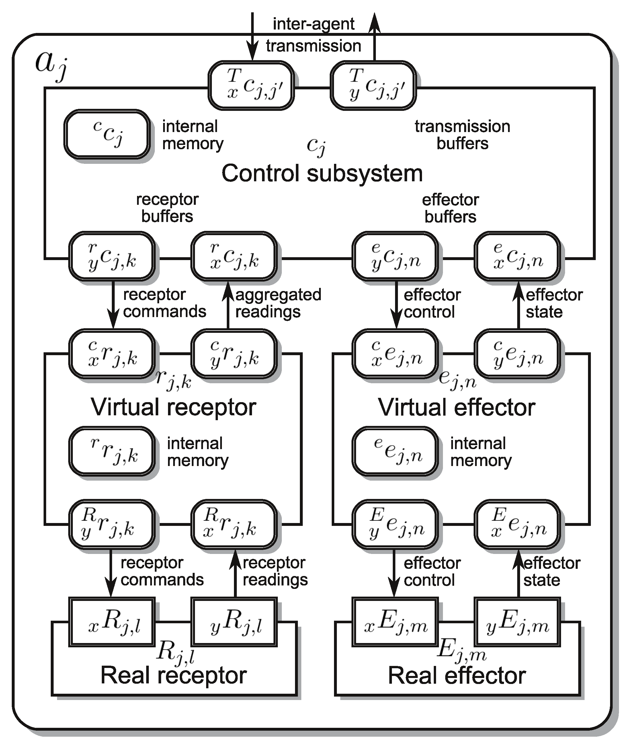
An embodied agent
a is subdivided into subsystems, namely: a single control subsystem
c and zero or more virtual and real effectors (
e and
E, respectively) and zero or more virtual and real receptors (
r and
R, respectively) (
Figure 1) [
27,
28,
58,
59,
60]. As only the control subsystem of an agent has the capability of interacting with other agents (precisely speaking with their control subsystems) this subsystem will be the focus of our attention. The primary activity of the control subsystem
of an agent
, is the computation of the control subsystem transition function
(
m is the name of the particular function), which in the decomposed form can be presented as:
From the point of view of inter-agent communication, the utilisation of the transmission input buffer
and output buffer
is most important. Whenever
is used,
is the only partial function producing the contents of the output buffer
. Thus, only the partial transition function
produces the response of the agent
to the messages inserted into
by the other agents. However, all partial transition functions use
to compute the commands for other subsystems of the agent
; thus, the obtained message influences all the activities of the agent. The transition function (
1) takes in its arguments at discrete time
i and computes the values dispatched to the other subsystems at time
. This defines the subsystem sampling time. Hence the elementary action of a subsystem is defined for a single sampling period and consists of:
Computation of the transition function and assigning the computed values to appropriate components of the output buffer and internal memory ,
Dispatching the contents of to the associated subsystems,
Incrementation of the discrete time counter i,
Acquiring into new input values from the cooperating subsystems.
This elementary action is iterated until a predicate
, called the terminal condition, or
, called an error condition, becomes true. The process of iterating the elementary action is called a behaviour
and can be represented by a graph (
Figure 2). As behaviour depends on the transition function, terminal condition and error condition, it is parameterised by all of them:
(
,
,
); however, for brevity the dependence on
will be neglected. Once behaviour
terminates its actions, another behaviour has to be chosen. This choice is based on a predicate
, called the initial condition (
m and
are the designators of the nodes connected by the directed arc labeled by
). Initial conditions label the directed arcs connecting the nodes of a graph representing a Finite State Machine (FSM)
. With each of its nodes (states)
, a behaviour
is associated; thus, switching states switches behaviours. As initial conditions are parameterised by the contents of input buffers, here again the acquired message influences the activities of the agent. Hence the messages introduced into the input buffer
can influence the activities of an agent in three ways:
In each iteration of the behaviour through the influence on the values computed by the iterated transition function (
1),
By terminating the behaviour, i.e., by causing the terminal condition to be satisfied,
By selecting a new behaviour, i.e., by causing an adequate initial condition to become true.
All these ways of influencing the activities of an agent result from the assumed model of an embodied agent. However, the designer of the system can also exert influence on the structure of the FSM . Some of its states can be distinguished as communication states (a single such state is quite common), in which the behaviour of the agent waits for a message. Once a message is obtained, the FSM reacts to it by directing the execution to an appropriate section of the FSM, which is responsible for the execution of a set of behaviours that compose a service—a service-oriented architecture (SOA) results. At each of the four mentioned communication levels, FIPA messages can be utilised.
It should be noted that this propagation of the received message through the four levels of the agent execution structure is beneficial from the point of view of the agent’s reactivity to outside stimuli, i.e., incoming messages. Each message can be accessed at the control subsystem sampling rate. If the currently executed service has to be interrupted, e.g., due to the request for a higher priority service, this subsystem, and hence the agent, will detect this through the evaluation of the terminal condition associated with the currently executed behaviour. The satisfaction of the terminal condition will cause the current behaviour to be aborted, and that in turn will initiate the evaluation of the initial condition, what will result in switching the FSM state, e.g., the state responsible for invoking the newly requested service. Such an instantaneous switch from one service to the other might not be possible, e.g., if the current service consists in the delivery of a cup of tea to the user, this cup cannot be simply dropped to start the execution of the higher priority service. In this case the FSM will need to pass through an intermediate state, in which it will execute a behaviour of placing the cup in a safe location, and only then proceeding to the execution of a new service.
It is worth noticing that in the case of complex robotic systems, e.g., cognitive robots, their control systems contain many CT type agents [
28,
61], i.e., computational agents, having the capability of communicating with other agents, but lacking effectors and receptors. In this case (
1) becomes:
In other words, the activities of the FSM of such an agent (its control subsystem, to be precise) mainly rely on the inter-agent communication, i.e., the contents of the messages transferred between such agents. Thus, is of paramount importance.
3.3. Structure of a Communicate
To take into account all the necessary possibilities of message contents, we propose that the contents of the output and input buffers—a communicate—be set in accordance with the IEEE FIPA standards. The partial transition function
should produce the content of the output buffer
as a message
(where
j and
are the designators of the communicating agents) and accept the content of the input buffer
in the format of
(see
Figure 3). A communicate transmitted from agent
to agent
at instant
i is a tuple:
The tuple
, according to FIPA ACL Message Structure Specification standard [
62], contains the following items:
Performative verb
, where
is a set of possible performative verbs defined by [
62]:
accept-proposal, agree, cancel, cfp, confirm, disconfirm, failure, inform, inform-if, inform-ref, not-understood, propagate, propose, proxy, query-if, query-ref, refuse, reject-proposal, request, request-when, request-whenever, subscribe}. It defines the intention of sending the communicate (request, inquiry, statement, etc.), and how the recipient of the message should interpret it.
Content of the communicate. If the language is provided, the content should conform to the syntax and semantics of that language.
Name of language used to formulate the content, where is a set of languages used for the formulation of contents of the communicates. Proper indication of the language expressing the content of each message helps the sender of the message to correctly formulate the content of the message, and the recipient to correctly understand this content. The FIPA standard does not require a language to be defined (no syntax and semantics are required). Different languages can be assigned to different communicative acts between pairs of agents.
Name of the ontology , where is a set of ontologies. An ontology defines the meaning and relations between symbols used in the message content. An ontology is needed when it is not enough to define the language and performative verb to understand the message content correctly, and also when the agent does not have the common knowledge required for its operation. The ontology determines for the agent how to understand the message in the context of knowledge that the ontology specifies.
Name of the interaction protocol
, where
is a set of possible interaction protocols defined by [
62]:
query, request, subscribe, request-when, cfp, icfp, propose,...}. It defines the pattern of interaction governing the conversation. The protocol organizes the exchange of messages and determines their order. Conversation between agents is usually bi-directional, and the goal is not only to pass an information item, but also to request and obtain a piece of information, to query the other agent, subscribe to a specific piece of information, etc. Thus, pairs of input and output buffers are considered (
,
); and for the sake of brevity, the pair is denoted as
.
Reply-by , is a timestamp indicating the latest time by which the reply to this communicate should be produced.
Reply-with identifier and in-reply-to identifier . The pair of identifiers is used to combine messages into short-term conversations. If the sender of the message wants the recipient’s reply to match the message it sent, it should set the identifier value. In turn, the recipient who wants to refer to the message with the identifier should set this value in .
Conversation identifier identifies the ongoing sequence of communicative acts that together form a conversation.
The figure is a set of timestamps, and is a set of identifiers of communicates sent. While is a set of all communicates. The symbol is a function mapping a message to its identifier. The set of all messages that can be sent by the agent is denoted as . The set of all messages that can be received by the agent is denoted as .
5. Illustrative Example: Robot Companion
The herein presented illustrative example shows how to apply the proposed design method. It is purposefully kept simple to let the reader concentrate on the method, however the resulting system is of utility. The purpose of a robot companion is to assist users (usually elderly) at their homes. A survey of robot tasks that the elderly person might request is presented in [
64]. A robot companion, as pointed out in [
65,
66], should exhibit the following capabilities: (1) moving around in the user’s home; (2) being safe for humans, household appliances and furniture; (3) being aware of the dynamic environment; (4) having a simple and intuitive human-robot interface (e.g., voice, display, gestures, tactile); (5) possessing manipulation capability; (6) having a friendly look; (7) having its own task management. A robot companion should be versatile and address as many requests of the elderly as possible. However, there are still technology limitations that force robot specialization. The mentioned range of tasks for a companion robot is wide, therefore an analysis of the requirements set for a specific robot should be carried out and a selection has to be made.
5.1. Formulation of Requirements
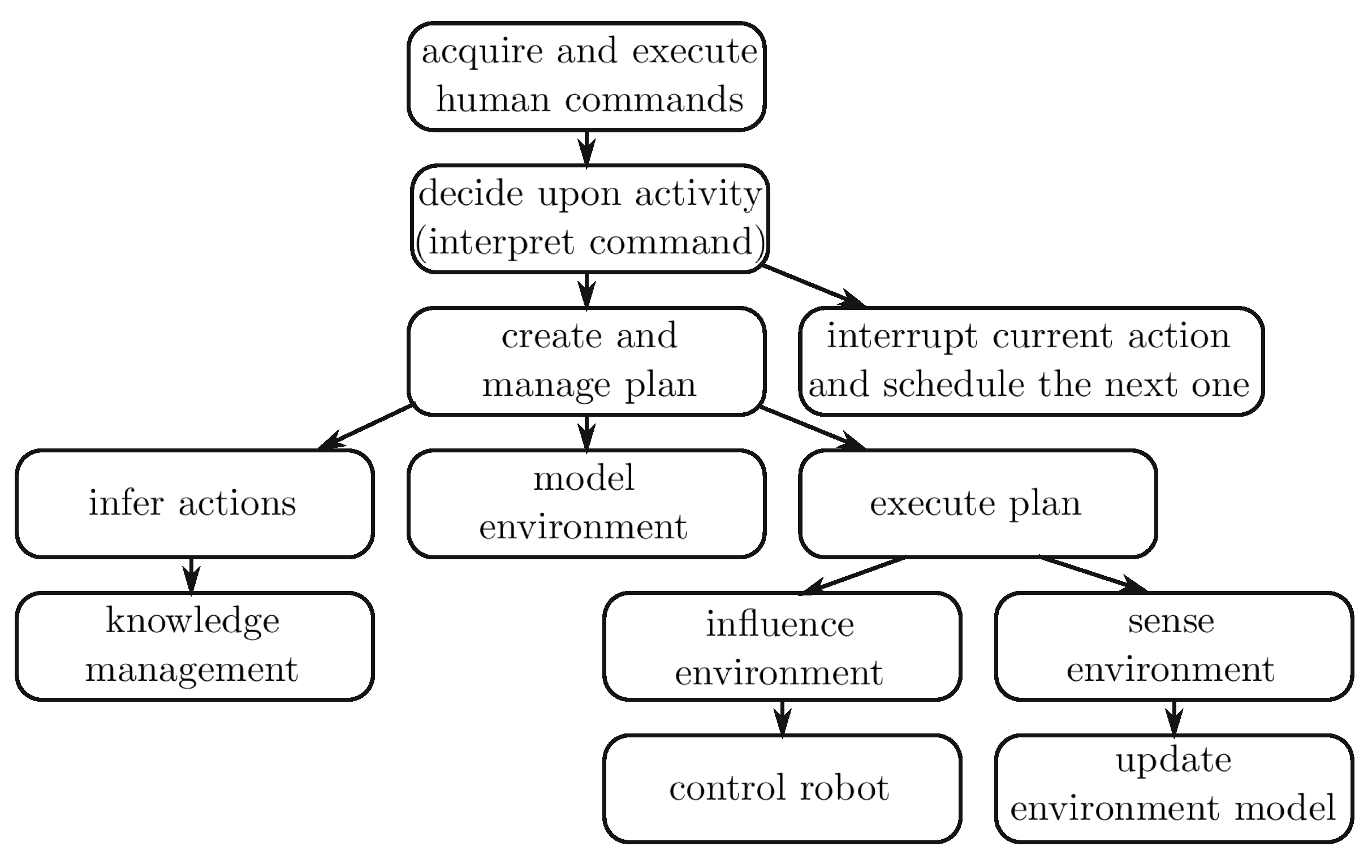
For brevity, we shall focus on the Robot Companion helping in a kitchen. The above general requirements should be analysed from the point of view of the chosen task. The most general requirement for the Robot Companion is that it should be able to acquire and subsequently execute human commands. Next, the robot should decide upon the necessary activity, i.e., interpret the command. To be able to perform the activity, there is a need for creating and managing a plan and afterwards executing it. As the Robot Companion interacts with an elderly person, who can change his/her mind, it is crucial for it to be able to interrupt the action currently performed and schedule the next one. To plan in a kitchen environment, the Robot Companion must be able to model this environment. The environment in which it works is dynamic, so in order to correctly plan its activities, the Robot Companion should deduce what activities it should perform. Moreover, it must identify and understand relationships (including spatial ones) between objects, both existing currently and those that will result from the execution of the plan. To execute the plan, it has to be able to sense and influence the environment using appropriate sensors and actuators. The environment is dynamic, because the robot and other agents change the positions and orientations of objects, thus, the Robot Companion should be able to update the environment model. The hierarchy of proposed requirements is presented in
Figure 5.
5.2. Decomposition of the Robot Companion
The Robot Companion can be treated as a monolithic system represented as a group of agents . For brevity, only two decomposition steps (the first and fourth) are described in detail, the remaining are only outlined.
The first decomposition is due to the requirement at the root of the tree (see
Figure 5) that says that a robotic system should acquire and execute human commands. The division
results in two agent groups:
These two groups communicate by sending commands and responses. In general, communication channels
created in the successive steps of the decomposition process are marked by consecutive integers
k. Those numbers remain unchanged during the design process. Moreover, those channels are also marked with the symbols of the groups, however, those will evolve. The communication channel
is created between groups
and
(
Table 1).
The second division results from the requirement that the robotic system interprets the commands obtained from a human, and decides about the command to be executed first. The group is decomposed into: (human-machine interface), and (decides upon command to be executed). It results in reallocation of the communication channel , and creation of the new one: , that is used to pass interpreted human commands.
The third division results from the requirements that demand the creation and management of a plan, and allow the interruption of the current action and scheduling the next one. The group is divided into (coordinates command execution and scheduling), and (creates and manages a plan). Two channels are reallocated: , . Also, a new one is created: , that is used to request for plan generation.
In the fourth step the designer takes into account that the Robot Companion should infer actions, model the environment and manage the knowledge (see
Figure 5). Inference of actions requires a component responsible for creating abstract plans:
(pl for planner). In turn, the group responsible for knowledge management will provide knowledge about the objects and relationships between them:
(km for knowledge manager). Thus, the group
is split into two:
(see
Table 2). There is a need to reallocate the channel
and it is obvious that it will be handled by the group responsible for creating the plan:
. A new channel
must be created between the new groups to enable the transfer of knowledge extracted from the knowledge base.
In the fifth step, we take into account that the robotic system must execute the plan, influence and sense the environment by controlling the robot. Thus, is decomposed into: (responsible for influencing and sensing the environment by operating the hardware) and (responsible for executing the plan). is reallocated: . Two communication channels are created: , where the low-level commands for the hardware, i.e., acquiring sensor readings and controlling the actuators, are transmitted, and passing the knowledge needed by .
The last step takes into account that the robotic system should update the environment model. As there already exists a group responsible for managing the environment model (), and sensor data are provided by , and a communication channel exists already; thus, only the content transmitted by this channel has to be supplemented.
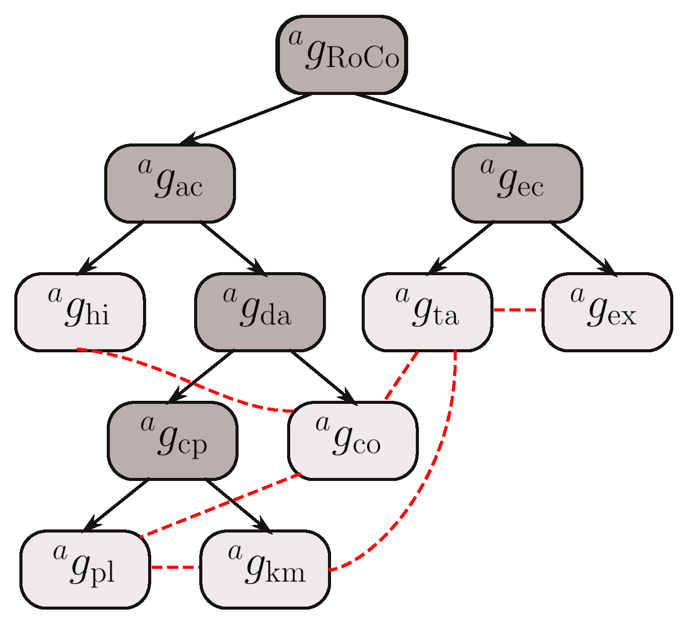
After exhausting the requirement tree, the decomposition process is complete. Six groups of agents emerged (see
Figure 6). Again for brevity the description of decomposition of
, that controls the robot hardware, has been omitted here. Hardware configuration is described below. Five groups (
,
,
,
,
) are transformed into respective agents:
. Those agents have clearly defined and coherent tasks.
generates a plan based on problem definition;
manages the knowledge database;
coordinates a set of commands received from a human, orders plans from
, and schedules their execution;
executes the plan and dispatches low-level instructions to
;
acts as a human-machine interface. Further decomposition would result in too much fragmentation and too much communication effort. Moreover, during decomposition, six communication channels were identified:
.
5.3. Hardware Configuration
The Velma robot (
Figure 7) has adequate capabilities to satisfy
requirements. Thus, it became the hardware part of the Robot Companion [
67]. It is the torso of a humanoid robot with two KUKA LWR arms and additional F/T sensors embedded in the wrists to which three-fingered BarrettHand grippers are attached. The torso is mounted on a 1 DOF revolute column which also supports a 2 DOF neck equipped with cameras and Kinect sensor (the head). Arms are torque controlled, employing impedance control [
67,
68]. The control laws offer two basic modes of operation: Cartesian and configuration space [
69]. The neck and grippers are position-controlled. The control system is implemented using the FABRIC programming framework [
70].
5.4. Specification of Communication Channels
At this stage of design, the messages sent between pairs of agents need to be refined, leading to the specification of the interaction protocols. Each communication channel should have a specified set of interaction protocols according to which the conversations take place. Moreover, every interaction protocol should contain: performative verbs, languages that specify the content of the messages, and possibly the ontologies. Due to the limited space, only two communication channels are described. However, the creation of the remaining follows the same pattern.
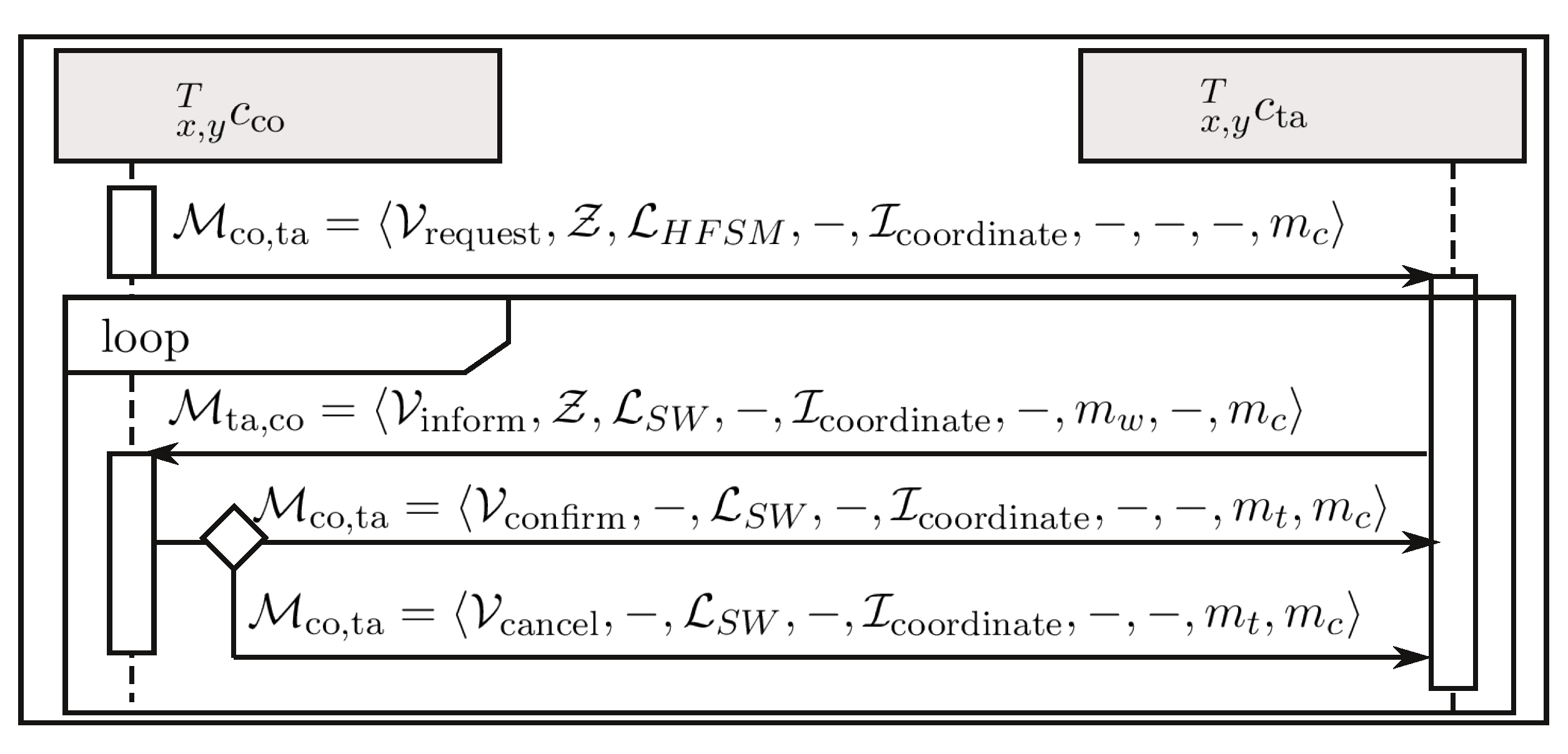
The communication channel is used to send plans to be executed. The first message deals with requesting from to execute the plan. The plan should be understandable to the agents; therefore, the task notation using HFSM (HFSM for Hierarchical Finite State Machine) is chosen. As requests from , the performative verb is , and the content is expressed using . is used for requesting the execution of the generated plan; thus, a typical message is up to dozens of kB.
While executing the plan, sends its status (name of its current state). Together with the performative verb it sends from a specified set of states: {Idle, Run, Error, Terminating, Finished, Failed, Replan}. The language (SW for Supervised Worker) was proposed to organize the list, thus, should be formulated using . The detailed description of is as follows. Idle—awaiting for the next plan. Running—executing a plan. Error—the plan execution ended with an error. Terminating—the plan execution is being terminated. Succeeded—the plan is finished with success. Preempted—the plan is preempted due to an interruption from . Replan—the plan cannot be further executed and a new plan is required.
The agent confirms each message it receives from by a message with the performative verb and empty content, as the intention provides complete information.
In the case when the plan has to be interrupted,
sends an interrupting message to
. The performative verb is
, and again sending any content is not necessary. The messages sent with
have no content, so their size is 100 to 200 bytes, and are sent every time
modifies its internal state. The detailed specification is presented as follows.
These four messages make up the interaction protocol
. The interaction protocol managing the conversation between
and
, together with the detailed formulation of the messages is shown in
Figure 8.
The communication channel
is used to transmit knowledge, in the form of queries produced by
, and answers formulated and sent by
. For both agents, to understand the queries and knowledge, the language
(WM for World Model) is proposed. The agent initiating the conversation is
, asking for knowledge using
expressed using
. The ontology
specifies the knowledge about the robot’s environment. It is built from scratch in OWL to keep it as simple as possible. The ontology was inspired by the KnowRob2 project [
71]. It was used to implement a simple knowledge base. The performative verb for the message is
. Agent
formulates the answer to the query, and informs the inquirer; thus, the performative verb is
.
The interaction protocol
, together with the detailed formulation of the messages is presented in
Figure 9. After designing the six communication channels, the system shown in
Figure 10 results.
The size of the content formulated using depends on the purpose of the message, e.g., requests are up to 250 bytes, but the size of answers depends on particular knowledge—from 250 bytes (in the case of, e.g., state of the gripper) up to 1 MB (in the case of complex or accurate information about the environment). The messages are sent every time the knowledge is needed, i.e., mainly during plan generation.
5.5. Agents in the Robot Companion System
Having defined the communication between agents, we can proceed to the specification of the embodied agents themselves. A crude specification of the agents arises from the system decomposition, however, a more detailed description is required. Thus, a brief description of key behaviours and specification of the FSMs governing them, for each agent, is presented below (
Figure 11). All of the agents considered here (
Figure 10) contain only their control subsystem—they are purely computational agents.
The objective of the coordinator agent
is to select one task out of all the tasks requested and coordinate its execution. The problem of task execution coordination and its solution for service robots is published in [
72,
73].
Based on configurable parameters and the scheduling algorithm,
decides when to switch the plan being executed by
to another one. The agent manages the procedure of suspending the current and starting the next plan execution. The FSM
of the control subsystem
of the agent
is tailored to fit the Robot Companion requirements. The FSM has 5 states (
Figure 11a). A brief description of the behaviours executed in each of them is shown in
Table 3. The agent receives the communicates from
in state
, from
in state
, and from
in all states.
The purpose of
is to generate the plan on demand of
, in response to
. During plan generation it may need additional knowledge, so it queries
using
. The activities of the control subsystem
of the agent
are governed by the FSM shown in
Figure 11b. In each state of the FSM, an associated behaviour is executed (
Table 4).
The agent
is responsible for query answering and for updating the knowledge database. At initialization the agent starts the
protocol, which results in receiving updates on the environment states. Its activity is governed by the FSM shown in
Figure 11c. In each state of the FSM, a corresponding behaviour is executed (
Table 5).
The agent
communicates with
,
, and
. It receives plans and plan execution interruption messages from
by means of
. In reaction to the plan execution and interruption requests the
states are switched. For the sake of brevity the communication with
is not presented. The FSM that governs the activity of
is shown in
Figure 11d. In each state of the FSM, a corresponding behaviour is executed (
Table 6).
5.6. Implementation
The system is implemented using ROS 1. The message exchange was performed using the Remote Procedure Call (RPC) mechanism. Agents are implemented as ROS nodes.
The standardized message format, proposed by IEEE FIPA standards, and specified in this article, is treated as a design pattern from the system implementation point of view. It is implemented as an ROS service, and used for all agents. The interaction protocols of the agents are specified with the ClassInterfaceInfo class. Thus, communicates of any agent are specified by filling elements of IEEE FIPA standard communicate. For example, the interaction protocol
is specified as:
where ‘request’ is the performative, ‘generatePlan’ is the query name, ‘[GroundTaskNetwork]’ is the request content class expressed in
, ‘HierarchicalPlan’ is the response content class given in
. Besides enforcing IEEE FIPA communicate standard, the ClassInterfaceInfo class verifies if the content follows the specified language. The part of the code responsible for communication has been separated, and used as programming modules. The modules implement, e.g., the ClassInterfaceInfo class, all interfaces for all agents and variety of world model objects being transmitted between the agents.
The standardization of interaction protocols enabled verification of the implementation against the specification. It made it easier to verify the implementation of agents by checking that all kinds of queries are supported at the agent code level and that the arguments and returned value comply with the specification. Due to structured messages and well-organised communication at the abstract agent-level, it is straightforward to implement query checks in the agents and analyse inter-agent communication abstracting from the implementation details. The approach presented in this article requires the definition of six communication languages used in the system. Due to that the organization of data structures into a hierarchy of classes emerged.
5.7. Experiment
In the previous sections, the proposed method was used to design a robotic system, then its implementation was described. The experiment presented herein verifies that the thus-produced specification conforms to the requirements. Moreover, the characteristics of the designed communication are assessed. The mentioned characteristics are as follows: the size of communicates, number of them, and frequency of their occurrence in specific timeframes.
The sizes of the messages were estimated in
Section 5.4, but their true sizes, their number and frequency of occurrence, depend on particular tasks that the robotic system executes. Therefore, in order to determine whether the communication between the individual components of the system is efficient, these characteristics should be verified in simulations, and then in the real robotic system. The approach for testing the communication is also sketched. Due to limited space, only one test case is described.
The designed robotic system was run under the following conditions. The group
is built of robot hardware components and software running on a machine with 4 core CPU and Linux OS with RT (real time) kernel. The software is semi-automatically generated from the specification using FABRIC [
70] and it meets hard RT requirements. The remaining agents, i.e.,
,
,
,
,
do not require hard RT, and they are deployed on another machine with Linux OS and ROS 1. Both machines are connected by a LAN using an Ethernet cable.
In the presented experiment, a complex task was performed that employs interleaved planning and execution. The experimental task was to pour content of a jar into a bowl. Both objects were initially located in an open cabinet. A video of the experiment is available at the link:
https://vimeo.com/720200335 (accessed on 21 October 2022). The provided video, as well as
Table 7, show that the requirements imposed on the system, as stated in
Section 5.1, are fulfilled.
During the experiment the occurrence of each message was logged along with the metadata (size, sender, recipient, performative, and interaction protocol) and the time at which it was sent. Based on this information, the detailed analysis presented below was carried out.
The execution of a given task took 778 s. and required 1856 messages to be exchanged between the agents. A timetable summarizing the experiment is shown in
Table 7.
Agents
,
,
,
and
share the same codes for inter-agent communication. The intensity of communication in the whole system is presented in
Figure 12. There is intense communication from 97 up to 152 s. (planning #1), and a few other communication episodes. There are two planning processes. In the first one (#1) the robot plans how to take the jar and bowl out of the cabinet, and put the bowl on the table. In the second one (#2) the robot plans how to pour the contents of the jar into the bowl.
86% of the sent messages is below 0.5 kB, but there are larger ones too, going up to 852 kB. This shows a great variety of the size of communicates. During execution of a command, agents apply specific communication, depending on the current situation (see
Table 7). The difference in the size of the communicates is in line with the estimates of the various types of them made in
Section 5.4.
The number of messages sent and received by particular agents is presented in
Table 8. Most of the communication is carried out by agents
and
through the communication channel
. For the whole planning process #1 the required bandwidth is on average 32 kbps, but the peak (150 kbps) is at the end of the first planning process (sec. 153) (see
Figure 13). The number of communicates sent in planning #1 is equal to 1598. Later on, the channel is not used (154–680 s), up to 681–682 s. where the planning #2 is done. 57 communicates are exchanged, with average bandwidth equal to 32 kbps. In total, the minimum size of the communicate is 231 b, the maximum is equal to 98 kb, and the average size is 654 b. It shows the accuracy of the predictions made during the construction of the communication channels (see
Section 5.4). The distribution of messages over time is difficult to estimate accurately. The size of the message querying
is small, as it contains only the specification of the knowledge needed. However, the size of the reply from
depends on the specific piece of knowledge. The communicate size can be small (up to 1 kb), e.g., information on the gripper state, or creation of the hypothetical state of the knowledge base; large (dozens of kb), e.g., sequence of positions of the bowl held by the gripper, possible grasps of the jar; or even very large (up to 100 kb), e.g., the current state of the whole environment.
6. Conclusions
The article presents a method of designing robotic systems, which puts the communication between system components at the forefront. This systematic design method facilitates system implementation and enables experimental evaluation of its characteristics, thus confirming that it fulfills the requirements, and that the communication between the system components is correct. This strengthens the authors’ claim that the communication-focused top-down robotic system design method based on binary decomposition is correct and useful. Decomposition based top-down design methods, if applied systematically, assure that the resulting system fulfils the requirements, as opposed to bottom-up synthesis techniques, which produce emergent system properties, which have to be deduced and subsequently tested against the requirements. Moreover, it uses the standardization of the message structure for communication within robotic systems composed of agents based on the IEEE FIPA standard, known from multi-agent systems. In contrast to a commonly used bottom-up approach, where designers take components from a library or a framework and connect them complying with their interfaces, the proposed method is strictly top-down. It separates the specification of the system from its implementation. It shows how to systematically decompose groups and connect them by communication channels.
The communication focused system decomposition enables the analysis of the communication on the abstract agent-level. Organized communication and its properly defined specification facilitates the system’s further development. System-specific messages and language definitions are grouped and separated from the implementation. The implementation of the software that handles the communication process is generic. Therefore, there is no need to test the software multiple times. Only verification against the system specifications is required.
Highlighting communication in the design process shows the critical aspects of its operation. The bandwidth of communication channels and communication intensity can be estimated in the development. On their basis, it is possible to properly define or redefine the architecture of the entire robotic system and avoid bottlenecks. Application of the communication focused system decomposition method, with adequately defined requirements, allows for designing a robotic system with optimal control and energy consumption.


