Abstract
Ultra-supercritical circulating fluidized bed (CFB) boilers are taking up an increasing proportion of the CFB boiler fleet in China, making the safety concern about the heating surfaces in this type of boilers under sudden electricity failure draw more and more attention from the industry. For the time being, however, few studies have made efforts to resolve this concern. Given this, the physical process in a 660 MW ultra-supercritical boiler during the electricity failure accident was precited with a comprehensive model composed of mass and energy conservation equations in this work. The tube temperature of the boiler components with the highest safety risk, i.e., the water wall and a superheater, was obtained to evaluate the safety of the heating surfaces. The results revealed that the tube temperature (about 516 °C and 544 °C) would be obviously lower than the maximum permissible temperature of the tube material (600 °C and 630 °C) even when electricity could be restored at the power plant, indicating that the heating surfaces in the 660 MW ultra-supercritical CFB boilers would generally be recognized to be safe under sudden electricity failure.
1. Introduction
To achieve its carbon peaking and carbon neutrality goals, great efforts have been paid by China to increase the share of renewables in power generation in the past few years. Even so, out of the consideration of ensuring the security of the energy supply, the share of thermal power generation still stands at 70% in China. Among all types of thermal power plants, circulating fluidized bed (CFB) power plants, especially the ones equipped with boilers of large capacity and high parameters (supercritical or ultra-supercritical), have gained increasing popularity for their higher energy efficiency and lower emission [1,2,3,4,5], and take up approximately 17% of China’s total power generation. Currently, over 20% of existing CFB power plants in China are equipped with supercritical or ultra-supercritical boilers. Since supercritical boilers are all once-through boilers, steam separators take the place of boiler drums in these types of boilers, which greatly reduces the water storage and heat capacity of the main steam system. This significantly increases the risk of a safety accident called sudden electricity failure for supercritical boilers.
The electricity failure accident refers to a situation where the electricity supply to a power plant is suddenly cut off. For a CFB power plant, the boiler would immediately shut down, meaning that the primary and secondary air fans, induced draft fan, coal feeders, and feed water pumps would all stop operating. Even though combustion has been basically inhibited at this point, tons of high-temperature bed materials in the furnace would continue to heat the heating surfaces. Contrarily, no fresh working fluid would flow through the heating surfaces to cool them down because of the shutdown of the feed water pumps, leading to the continuous increase in the tube temperature of the heating surfaces. Given the relatively low heat capacity of the main steam system in supercritical CFB boilers, questions have been posed by the industry on whether the heating surfaces, such as the water wall, would face over-temperature or even tube burst after an electricity failure accident happens.
Unlike most of supercritical CFB boilers, ultra-supercritical CFB boilers are usually equipped with external heat exchangers (EHEs) to provide extra heating surfaces. Therefore, under sudden electricity failure, not only the heating surfaces in the furnace, i.e., the water wall, but also the tube panels in the EHEs, i.e., the superheater, should be paid close attention to (the reason why the reheater could be excluded is that it is heated by the flue gas and thus has a lower heating rate). In this sense, although a couple of studies have been conducted on this topic, there still lacks a convincing conclusion for the safety of the heating surfaces in ultra-supercritical CFB boilers. Deng et al. [6,7] established a zero-dimensional model capable of predicting the tube temperature of the water wall during the electricity failure accident; however, the model was only applicable to supercritical CFB boilers without EHEs. Yao et al. [8] deeply analyzed the three-dimensional temperature field in the furnace of a 170 t/h CFB boiler during the electricity failure accident; however, the physical process in the water side was oversimplified in that work. Li et al. [9,10,11] carried out an electricity failure experiment in a 660 MW supercritical CFB boiler and established a mathematical model depicting the flow and heat transfer in the heating surface with the aid of the obtained measurement results. The effect of different parameters of the emergency supply pump on the safety of the heating surfaces was carefully investigated; however, in the model, the heat fluxes to the heating surfaces were simply derived from experimental data, making it difficult to be applied to other boilers despite having similar structures. Other studies have also been conducted on the transient process in supercritical boilers [12,13,14,15,16,17,18,19,20]; however, they are of little referential significance.
In light of this, it is of great importance to conduct research on the physical process in ultra-supercritical CFB boilers, especially the water side of the furnace and EHEs, during the electricity failure accident. In this work, aiming to provide insights into the safety of the heating surfaces under such conditions, the coupling effect between the working fluid in the water wall and superheater was described in detail. Based on this, a mathematic model that consisted of mass and energy conservation equations was developed, and the variation of the tube temperature of the water wall and superheater in a 660 MW ultra-supercritical CFB boiler was simulated. It turned out that even 2 h after the accident happened, the tube temperature of the water wall and superheater still did not reach the permissible value, which means that the heating surfaces in the 660 MW ultra-supercritical CFB boiler could be considered to be safe during the accident.
2. Physical Process in Typical Ultra-Supercritical CFB Boilers under Sudden Electricity Failure
2.1. Basic Information of the Investigated Ultra-Supercritical CFB Boiler
To ensure the representativeness of the investigated boiler, the 660 MW ultra-supercritical CFB boiler located in the Binchang Power Plant, Shanxi Province, China, is taken as the research object in this work. The boiler is manufactured by Harbin Boiler Company Limited and is mainly composed of a furnace with a single air distribution plate, four steam-cooled cyclones, four EHEs, and a twin tail dust. The schematic diagram of the boiler is shown in Figure 1, whereas the main design parameters of it are listed in Table 1.
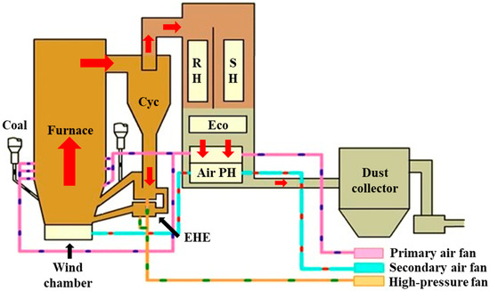
Figure 1.
Schematic diagram of 660 MW ultra-supercritical CFB boiler. PH: preheater, SH: superheater, RH: reheater.

Table 1.
Main design parameters of boiler.
The design fuel for the boiler is a mixture of coal gangue, slime, and raw coal, and its basic parameters are demonstrated in Table 2.
Table 2.
Basic parameters of the design fuel.
2.2. Steam and Water Flow Circuit of the Investigated Ultra-Supercritical CFB Boiler
To provide fundamental information for the simulation of the physical process in the water side during the electricity failure accident, the steam and water flow circuit of the investigated boiler should be analyzed first. As shown in Figure 2, after being preheated in the economizer located at the tail dust, the feed water would flow through the water wall and directly go into the steam separator. Then the separated steam would enter the low-temperature superheater at the tail dust, the medium-temperature superheater I and II in the EHEs, and the high-temperature superheater in the furnace, in turn, before leaving the main steam system. From the steam and water flow circuit, it can be found out that for all the heating surfaces in the boiler, only the water wall and medium-temperature superheater I and II are in direct contact with the bed materials and thus have larger heat transfer coefficients. In other words, the water wall and medium-temperature superheater I and II have the highest risk of over-temperature and tube burst among all the heating surfaces. In light of this, only the physical process in the water wall and medium-temperature superheater I and II are considered in this work. In addition, for the sake of convenience, the medium-temperature superheater I and II are assumed to be one entirety (hereinafter, the superheater) in the follow-up simulation.
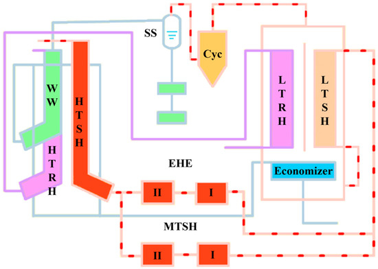
Figure 2.
Schematic of steam and water flow circuit of typical ultra-supercritical CFB boiler. LT: low-temperature, MT: medium-temperature, HT: high-temperature, WW: water wall, SS: steam separator, SH: superheater, RH: reheater.
2.3. Physical Process in the Bed Material Side
2.3.1. Physical Process in the Boiler Furnace
Considering that the primary and secondary air fans, induced draft fan, and coal feeders all immediately shut down after the electricity failure accident happens, the vast majority of bed materials would fall and stack on the air distributor because of gravity, forming a stationary bed at the bottom of the furnace. At the same time, combustion would be quickly inhibited due to the rapid reduction of oxygen concentration in the furnace. Therefore, it can be assumed that only the heat transfer process between the stacked bed materials and water wall exists in the furnace during the electricity failure accident, and this process is predominantly achieved by conduction between the fixed bed and bottom heating surfaces as well as surface radiation of the fixed bed.
2.3.2. Physical Process in the EHEs
Similar to the situation in the furnace, only heat transfer process exists in the EHEs during the electricity failure accident. Owing to the cutoff of fluidizing air, a fixed bed is formed at the bottom of the EHEs as well. Therefore, the heat transfer between the bed materials in the EHEs and superheater is achieved through two mechanisms: particulate phase convection and radiation between the bed materials and immersed heating surfaces as well as surface radiation between the fixed bed and exposed heating surfaces.
2.4. Physical Process in the Water Side
Under the condition of no manual intervention, the physical process in the water side would heavily depend on the dynamic response characteristic of a solenoid valve called the pressure control valve (PCV). The PCV is a type of overpressure protection device and is usually installed at the outlet of the superheater [7]. When the main steam pressure exceeds a preset value, i.e., the set pressure, the PCV would jump up to exhaust extra steam to the environment at a rate proportional to its certified capacity to lower the pressure in the steam–water system. On the other hand, when the main steam pressure falls below another preset value, i.e., the re-seating pressure, the PCV would shut again to avoid wasting the working fluid. Based on the aforementioned response characteristic of the PCV and the assumption that the main steam valve remains closed during the electricity failure accident, it can be inferred that the physical process in the water side would alternate between the following two steps:
- (1)
- Step 1: the gradual increase in the temperature and pressure in the main steam system. During this step, the PCV remains closed as the main steam pressure is still below the set pressure of the PCV. In this process, although there is no working fluid flowing out of the main steam system as the main steam valve is also closed (which is often the case), the pressure in the water wall is not always equal to that in the superheater, which leads to a non-negligible working fluid mass flow rate between these two devices. In the meantime, the working fluid in the main steam system is continuously heated by the bed materials in the furnace and EHEs, causing the incessant increase in the temperature and pressure in the system.
- (2)
- Step 2: the exhaust of the working fluid through the PCV. During this step, since the main steam pressure is higher than the set pressure of the PCV, the PCV would jump up and the working fluid in the main steam system would be exhausted to the environment, bringing about the decrease in pressure in the superheater. The PCV would shut again when the main steam pressure is reduced to the re-seating pressure of the PCV, making the physical process in the water side reenter step one. The physical process in the water side would continue to switch between these two steps until the boiler reaches thermal equilibrium.
3. Model Description
3.1. Modeling Approach and Hypothesis
To give an accurate description of the physical process in the furnace and EHEs during the electricity failure accident, the following modeling approach and hypotheses are adopted:
- (1)
- The physical process in the furnace and EHEs are considered, and both include three components: bed materials, tube wall, and working fluid.
- (2)
- The working fluid in the water wall and superheater as regarded as two entireties.
- (3)
- Mass and energy conservation are both taken into account.
- (4)
- The heat transfer between the furnace (EHEs) and environment is ignored.
The interactions between different components are demonstrated in the below figure (Figure 3).
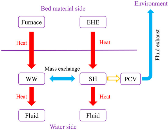
Figure 3.
Schematic of interactions between different components.
3.2. Governing Equations for the BED Materials
3.2.1. Governing Equations for the Bed Materials in the Furnace
Given that the primary and secondary air fans and induced draft fan all stop operating at the start of the physical process, the mass of the bed materials in the furnace can be assumed to remain unchanged during the process. Thus, there is no need to set up the mass conservation equation for the bed materials in the furnace.
As for the energy conservation equation, based on the first law of thermodynamics for closed systems, it is formulated as follows [7]:
where Qbt,fur is the heat flux between the bed materials and tube wall in the furnace, mb,fur is the mass of the bed materials in the furnace, Cb,fur is the specific heat capacity of the bed materials in the furnace, Tb,fur is the temperature of the bed materials in the furnace, while t refers to time.
Qbt,fur is composed of two parts, namely the conduction and radiation heat flux, and can be determined as
where hbt,c,fur and hbt,r,fur are the convective and radiative heat transfer coefficients between the bed materials and tube wall in the furnace, respectively, Abt,c,fur and Abt,r,fur are the convective and radiative heat transfer area between the bed materials and tube wall in the furnace, respectively, and Tt,fur is the tube temperature of the water wall.
According to previous literature [21], hbt,c,fur and hbt,r,fur can be given by
where hre is the heat transfer coefficient between the bed materials and refectory in the furnace, and δre and λre are the thickness and thermal conductivity of the refractory in the furnace, respectively.
where σ is the Stefan–Boltzmann constant, εb,fur and εt,fur are the emissivity of the bed materials and tube wall in the furnace, respectively, whereas Ab,fur and At,fur are the surface area of the bed materials and tube wall in the furnace (the former is equal to Abt,r,fur). Tb,eff,fur is the effective temperature of the bed materials in the furnace and is defined as
3.2.2. Governing Equations for the Bed Materials in the EHEs
Similarly, owing to the cutoff of the fluidizing air, only energy conservation needs to be considered for the bed materials in the EHE. Based on the first law of thermodynamics for closed systems, the energy conservation equation for the bed materials in the EHE can be formulated as follows:
where Qbt,EHE is the heat flux between the bed materials and tube wall in the EHE, mb,EHE is the mass of the bed materials in the EHE, Cb,EHE is the specific heat capacity of the bed materials in the EHE, and Tb,EHE is the temperature of the bed materials in the EHE.
Qbt,EHE consists of two parts as well, i.e., the heat flux between the bed materials and immersed and exposed tube wall in the EHE, and can be determined as
where hbt,i,EHE and hbt,e,EHE are the heat transfer coefficients between the bed materials and immersed and exposed tube wall in the EHE, Abt,i,EHE and Abt,e,EHE are the heat transfer areas between the bed materials and immersed and exposed tube wall in the EHE, respectively, and Tt,EHE is the tube temperature of the superheater.
According to the heat transfer model developed by Zhang [22], hbt,i,EHE can be calculated as
where hbt,p,cv, hbt,g,cv, and hbt,p,r are the heat transfer coefficients for particulate phase convection, gas phase convection, and particulate phase radiation, respectively. It should be noted that hbt,g,cv can be assumed to be zero as there is no macro flow in the EHE.
Moreover, hbt,p,cv and hbt,p,r can be given by [22]
where 1/hbt and 1/hbc represent the interface and internal thermal resistance of the bed materials in the EHE.
where εb,EHE and εt,EHE are the emissivity of the bed materials and tube wall in the EHE, respectively. Tb,eff,EHE is the effective temperature of the bed materials in the EHE and is defined as
As regard hbt,e,EHE, it has a similar form as hbt,r,fur:
where Ab,EHE and At,EHE are the surface area of the bed materials and tube wall in the EHE (the former is equal to Abt,e,EHE).
3.3. Governing Equations for the Tube Wall
During the process, unless tube burst occurs, the mass of the tube wall can be assumed to remain unchanged. Therefore, only the energy conservation equation needs to be set up for the tube wall.
3.3.1. Governing Equations for the Tube Wall in the Furnace (Water Wall)
By analogy to the derivation of the energy conservation equation for the bed materials, the equation for the water wall is obtained as follows:
where Qtw,fur is the heat flux between the water wall and the working fluid inside it, mt,fur is the mass of the water wall, and Ct,fur is the specific heat capacity of the water wall.
where htw,fur is the heat transfer coefficient between the tube wall and the working fluid in the water wall, Atw,fur is the heat transfer area between the tube wall and the working fluid in the water wall, and Tw,fur is the temperature of the working fluid in the water wall.
The Mokry correlation [23] is adopted to determine htw,fur:
where dt,fur is the diameter of the water wall, λt,fur is the thermal conductivity of the water wall, Ret and Prt are the Reynolds number and Prandtl number at reference temperature Tt,fur, respectively, while ρw,t and ρw,w are the density of the working fluid at reference temperature Tt,fur and Tw,fur, respectively.
Ret in Equation (15) is defined as
where is the working fluid mass flow rate between the water wall and superheater, and μw,t is the viscosity of the working fluid at reference temperature Tt,fur. In view of the fact that the average fluid mass flow in the water wall is actually 0.5 , the numerator in Equation (16) should be multiplied by a factor of 0.5.
3.3.2. Governing Equations for the Tube Wall in the EHEs (Superheater)
Using the same derivation method as in Section 3.3.1, the energy conservation equation for the superheater can be formulated as follows:
where Qtw,EHE is the heat flux between the superheater and the working fluid inside it, mt,EHE is the mass of the superheater, and Ct,EHE is the specific heat capacity of the superheater.
where htw,EHE is the heat transfer coefficient between the tube wall and the working fluid in the superheater, Atw,EHE is the heat transfer area between the tube wall and the working fluid in the superheater, and Tw,EHE is the temperature of the working fluid in the superheater.
htw,EHE can also be calculated by the Mokry correlation [23]; however, it should be noted that the Ret here should be defined as
where is the exhaust mass flow rate through the PCV and is calculated as
where wcer is the certified capacity of the PCV, Pw,EHE is the pressure in the superheater, Pw,cer is the rated pressure of the PCV, while vw,EHE and vw,cer are the specific volume of the working fluid at reference pressure Pw,EHE and Pw,cer, respectively.
3.4. Governing Equations for the Working Fluid
3.4.1. Governing Equations for the Working Fluid in the Water Wall
(1) Mass Conservation Equation
The change of the mass of the working fluid in the water wall originates from the mass exchange between the water wall and superheater, and thus the mass conservation equation can be given by
where mw,fur is the mass of the working fluid in the water wall.
(2) Energy Conservation Equation
Based on the first law of thermodynamics for open systems, the energy conservation equation for the working fluid in the water wall can be formulated as follows:
where Uw,fur is the specific internal energy of the working fluid in the water wall, and Hw,fur is the specific enthalpy of the working fluid in the water wall.
3.4.2. Governing Equations for the Working Fluid in the Superheater
(1) Mass Conservation Equation
Unlike the working fluid in the water wall, the variation of the mass of the working fluid in the superheater is the result of the mass exchange between the two devices and the exhaust of the working fluid, and thus the mass conservation equation can be given by
where mw,EHE is the mass of the working fluid in the superheater.
(2) Energy Conservation Equation
Based on the first law of thermodynamics for open systems, the energy conservation equation for the working fluid in the superheater can be formulated in the same way:
where Uw,EHE is the specific internal energy of the working fluid in the superheater, and Hw,EHE is the specific enthalpy of the working fluid in the superheater.
3.5. Determination of Working Fluid Mass Flow Rate between Water Wall and Superheater
The working fluid mass flow rate between the water wall and superheater has a significant impact on the physical process during the electricity failure accident as it largely determines the heat transfer coefficient between the tube wall and the working fluid inside it. Therefore, it is of great importance to accurately predict this parameter. To obtain , the following hypothesis and approach is adopted in this work:
- (1)
- For the sake of simplicity, among the three categories of pressure drop, only frictional pressure drop (accounts for the majority) is considered in this work.
- (2)
- The frictional pressure drop between the water wall and superheater ΔPfur,EHE is assumed to be directly proportional to , and thus ΔPfur,EHE can be calculated aswhere is the average specific volume of the working fluid in the water wall and superheater, vBMCR is the specific volume of the working fluid under the boiler maximum continuous rate (BMCR) condition, is the working fluid mass flow rate between the water wall and superheater under the BMCR condition, and ΔPfur,EHE,BMCR is the frictional pressure drop between the water wall and superheater under the BMCR condition.
- (3)
- Suppose a possible working fluid mass flow rate , use Equations (1)–(24) and the two below equations to determine the pressure in the water wall and superheater (Pw,fur and Pw,EHE) under the given .where vw,fur is the specific volume of the working fluid in the water wall.
- (4)
- Compare Pw,fur − Pw,EHE and ΔPfur,EHE (calculated from through Equation (25)). If the difference between these two values is lower than a preset threshold ε, then can be seen as . Otherwise, repeat (3) and (4) until |Pw,fur − Pw,EHE − ΔPfur,EHE| < ε.
4. Results and Discussion
4.1. Initial Values of the Simulation
Based on the design value of this 660 MW ultra-supercritical CFB boiler, the initial values of the simulation are listed in Table 3.
Table 3.
Initial values of simulation.
4.2. Physical Process under Sudden Electricity Failure
With the aid of the built-in ode113 solver in Matlab, the equation system composed of Equations (1)–(24) can be solved, and the total simulation time is set as 8000 s as electricity should able to be restored after this period of time.
4.2.1. Physical Process in the Bed Material Side
As demonstrated in Figure 4, during the electricity failure accident, the furnace and EHE bed temperature both gradually drop but at a decreasing speed. This phenomenon is more obvious for the EHE bed temperature as the heat flux between the bed materials and tube wall in the EHE declines much faster throughout the process. This is partly due to the larger percentage reduction in the temperature difference between the bed materials and tube wall in the EHE (58.6%) than that in the furnace (51.8%) from start to finish.
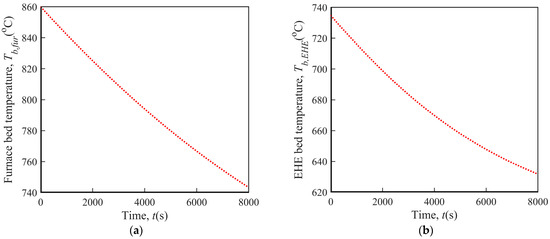
Figure 4.
Variation of bed temperature under sudden electricity failure. (a) Furnace bed temperature; (b) EHE bed temperature.
4.2.2. Physical Process in the Water Side
(1) Fluid Pressure
As illustrated in Figure 5, the fluid pressure in the water wall has a similar variation trend to that in the superheater. After reaching their maximum values (close to 35.2 MPa) at the start of the process, these two parameters enter a period of approximately equal-amplitude oscillation due to the intermittent exhaust of the working fluid. The upper and lower bound of the oscillation value are about 30.7 Mpa and 29.8 Mpa, which corresponds to the set and re-seating pressure of the PCV. Based on the premise that the main steam valve is closed during the electricity failure accident, the rapid increase in the fluid pressure in the water wall and superheater at the beginning of the process is caused by the sudden decrease in the fluid outflow rate from the main steam system as the PCV has a much lower certified capacity than the main steam valve (392 t/h vs. 1914 t/h).
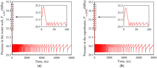
Figure 5.
Variation of fluid pressure under sudden electricity failure. (a) Water wall; (b) Superheater.
(2) Tube Temperature
Different from the furnace and EHE bed temperature, as shown in Figure 6, the tube temperature of the water wall and superheater takes on a first falling then rising trend. The reason why the tube temperature drops at first is that after the electricity failure accident happens, the heat flux between the bed materials and tube wall would rapidly decrease owing to the cutoff of the fluidizing air. Meanwhile, however, as a result of the exhaust of working fluid, the heat flux between the tube wall and working fluid would basically remain unchanged as before the accident occurs (heat transfer still occurs by forced convection). Therefore, the heat flux between the tube wall and working fluid would be larger than that between the bed materials and tube wall, making the tube wall lose some of its heat. Shortly afterward, with the gradual decrease in the temperature difference between the tube wall and working fluid inside it, the heat flux between the bed materials and tube wall would be higher than that between the tube wall and working fluid again, bringing about the simultaneous rise in the temperature of the tube wall and the working fluid inside.
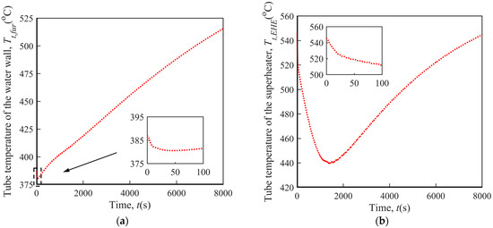
Figure 6.
Variation of tube temperature under sudden electricity failure. (a) Water wall; (b) superheater.
Moreover, for the tube temperature of the water wall, the length of the downward phase is relatively short as the initial temperature difference between the tube wall and the working fluid inside it is already quite small (<20 °C), meaning that there is not much room for a reduction in the tube temperature. Contrarily, the temperature difference between the superheater and the working fluid flowing through it is much larger as a portion of the working fluid is from the water wall and thus has a relatively low temperature. The larger temperature difference results in a longer downward phase for the tube temperature of the superheater.
In light of the facts that the tube temperature of the water wall and superheater is still well below the corresponding maximum permissible temperature (600 °C and 630 °C) when electricity can be restored and the maximum pressure in the main steam system during the accident is less than 9% higher than the normal operating pressure, the heating surfaces in the 660 MW ultra-supercritical CFB boilers can be considered to remain safe under sudden electricity failure.
(3) Fluid Mass
Surprisingly, the mass of the working fluid in the water wall shows a completely different variation trend to that in the superheater. As demonstrated in Figure 7, the fluid mass in the water wall presents an overall descending trend, while on the whole, the fluid mass in the superheater increases first and then decreases. The initial increase in the fluid mass in the superheater is caused by the reduction in the fluid temperature during this period, which is the result of the influx of lower-temperature working fluid from the water wall (the cooling effect of the influx fluid still plays a bigger role than the heating effect of the tube wall because of the relatively large temperature difference between the fluid in the water wall and superheater at this point). However, along with the decrease in the mass in the water wall, the working fluid mass flow rate between the water wall and superheater drops as well, the fluid mass in the superheater then progressively decreases due to the subsequent rise in the fluid temperature. In addition, it turns out that the interval between two adjacent drops in the fluid mass in the superheater becomes longer, indicating that the fluid exhaust frequency would decrease with time during the electricity failure accident.
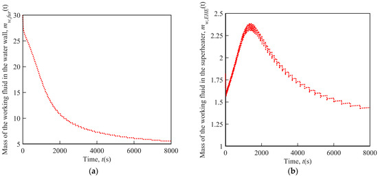
Figure 7.
Variation of fluid mass under sudden electricity failure: (a) Water wall; (b) superheater.
5. Conclusions
The safety of the heating surfaces in ultra-supercritical CFB boilers under sudden electricity failure has remained to be an unresolved question in the industry. Nevertheless, existing studies cannot fully address this issue. Therefore, in this work, based on the in-depth analysis on the physical process in both the bed material and water side during the electricity failure accident, a mathematical model that consisted of mass and energy conservation equations was set up. Using this model, the variation of a few key parameters in a 660 MW ultra-supercritical CFB boiler during the accident was predicted, and a preliminary conclusion on the safety of the heating surfaces under sudden electricity failure can be made.
To sum up, the main conclusions of this work are shown as follows:
- During the electricity failure accident, the bed temperature gradually dropped but at a decreasing speed, whereas the tube temperature took on a first falling then rising trend. In contrast, after reaching the maximum value, the fluid pressure in the heating surfaces went through a process of approximately equal-amplitude oscillation.
- Under the steam and water flow circuit design reported in this work, the safety of the heating surfaces in the 660 MW ultra-supercritical CFB boiler could be guaranteed for there is enough time for electricity to be restored.
Author Contributions
Conceptualization, B.D.; Data curation, T.Z.; Methodology, X.J.; Supervision, M.Z.; Validation, H.W.; Visualization, S.Z.; Writing—original draft, B.D.; Writing—review & editing, H.Y. All authors have read and agreed to the published version of the manuscript.
Funding
This work was financially supported by the National Key Research Plan (2019YFE0102100) and the Heilongjiang Key Achievements Transformation Project (CG18A002).
Data Availability Statement
Not applicable.
Conflicts of Interest
The authors declare no conflict of interest.
Nomenclature
| A | Area (m2) |
| C | Specific heat capacity (J/kg·K) |
| d | Diameter (m) |
| H | Specific enthalpy (J/kg) |
| h | Heat transfer coefficient (W/m2·K) |
| m | Mass (kg) |
| Mass flow rate (kg/s) | |
| Pr | Prandtl number (-) |
| Q | Heat flux (W) |
| Re | Reynolds number (-) |
| T | Temperature (K) |
| t | Time (s) |
| U | Specific internal energy (J/kg) |
| v | Specific volume (m3/kg) |
| w | Capacity (kg/s) |
| Greek letters | |
| δ | Thickness (m) |
| ε | Emissivity (-) |
| λ | Thermal conductivity (W/m·K) |
| μ | Viscosity (kg/m·s) |
| ρ | Density (kg/m3) |
| Subscripts and superscripts | |
| b | Bed materials |
| BMCR | Boiler maximum continuous rate |
| bt | Bed materials to tube wall |
| c | Conduction |
| cer | Certified |
| cv | Convection |
| e | Exposed |
| eff | Effective |
| EHE | External heat exchanger |
| exh | Exhaust |
| f | Flow |
| fur | Furnace |
| g | Gas phase |
| i | Immersed |
| p | Particulate phase |
| r | Radiation |
| re | Refractory |
| t | Tube wall |
| tw | Tube wall to working fluid |
| w | Working fluid |
| Abbreviations | |
| BMCR | Boiler maximum continuous rate |
| BRL | Boiler rated load |
| CFB | Circulating fluidized bed |
| EHE | External heat exchanger |
| PCV | Pressure control valve |
| PH | Preheater |
| RH | Reheater |
| SH | Superheater |
| SS | Steam separator |
| WW | Water wall |
References
- Cai, R.; Zhang, H.; Zhang, M.; Yang, H.; Lyu, J.; Yue, G. Development and application of the design principle of fluidization state specification in CFB coal combustion. Fuel Process. Technol. 2018, 174, 41–52. [Google Scholar] [CrossRef]
- Ke, X.; Cai, R.; Zhang, M.; Miao, M.; Lyu, J.; Yang, H. Application of ultra-low NOx emission control for CFB boilers based on theoretical analysis and industrial practices. Fuel Process. Technol. 2018, 181, 252–258. [Google Scholar] [CrossRef]
- Lyu, J.; Yang, H.; Ling, W.; Nie, L.; Yue, G.; Li, R.; Chen, Y.; Wang, S. Development of a supercritical and an ultra-supercritical circulating fluidized bed boiler. Front. Energy 2019, 13, 114–119. [Google Scholar] [CrossRef]
- Wang, W.; Li, Z.; Lyu, J.; Zhang, H.; Yue, G.; Ni, W. An overview of the development history and technical progress of China’s coal-fired power industry. Front. Energy 2019, 13, 417–426. [Google Scholar] [CrossRef]
- Liu, X.M.; Yang, H.R.; Lyu, J.F. Optimization of fluidization state of a circulating fluidized bed boiler for economical operation. Energies 2020, 13, 376. [Google Scholar] [CrossRef]
- Deng, B.Y.; Zhang, M.; Lyu, J.F.; Yang, H.R. Analysis on the safety of the water wall in a 350MW supercritical CFB boiler under electricity failure condition. Proc. CSEE 2019, 39, 4799–4807. [Google Scholar]
- Deng, B.Y.; Zhang, M.; Lyu, J.; Li, S.; Yang, H. Safety analysis on the water wall in the 350 MW supercritical CFB boiler under sudden electricity failure. Energy 2019, 189, 116364. [Google Scholar] [CrossRef]
- Yao, Y.; Jiang, L.; Deng, B.; Zhang, M.; Zhang, Y.; Yang, H.; Lyu, J. Heat transfer analysis of stationary bed materials in a CFB boiler after a sudden power failure. Fuel Process. Technol. 2021, 211, 106587. [Google Scholar] [CrossRef]
- Li, Y.L.; Dong, L.; Niu, T.T.; Yang, D.; Gong, L.M.; Zhou, X.; Lu, J.Y. Calculation and analysis on the safety of heating surfaces for a 660MW supercritical CFB boiler under boiler trip. Proc. CSEE 2021, 41, 5957–5965. [Google Scholar]
- Li, Y.L.; Yang, D.; Li, W.C.; Deng, Q.G.; Zhou, X.; Lu, J.Y.; Zhou, Q. Safety analysis of heating surfaces and selection of emergency water supply pump for a 660 MW ultra-supercritical CFB boiler under power failure condition. J. Chin. Soc. Power Eng. 2022, 42, 393–401. [Google Scholar]
- Li, Y.; Xie, B.; Bi, L.; Yang, H.; Nie, C.; Qing, H.; Yang, D. Experimental study and safety analysis on the heating surfaces in the 660 MW supercritical CFB boiler under sudden electricity failure. Energy Sci. Eng. 2022, 10, 2088–2105. [Google Scholar] [CrossRef]
- Tian, W.; Qiu, S.; Su, G.; Jia, D.; Liu, X.; Zhang, J. Thermohydraulic and safety analysis on China advanced research reactor under station blackout accident. Ann. Nucl. Energy 2007, 34, 288–296. [Google Scholar] [CrossRef]
- Go, G.; Moon, U.C. A water-wall model of supercritical once-through boilers using lumped parameter method. J. Electr. Eng. Technol. 2014, 9, 1900–1908. [Google Scholar] [CrossRef]
- Wang, D.F.; Xiao, K. Theoretical analysis and calculation of the unsteady heat transfer process of supercritical circulating fluidized bed boiler furnace under the emergency conditions. Boil. Technol. 2015, 46, 35–38. [Google Scholar]
- Zima, W.; Nowak-Oclon, M.; Oclon, P. Simulation of fluid heating in combustion chamber waterwalls of boilers for supercritical steam parameters. Energy 2015, 92, 117–127. [Google Scholar] [CrossRef]
- Li, G.; Zhou, X.; Zhou, Q.; Song, G.; Zheng, X.; Guo, Q. Study on the safety of water-wall after the BT of water supply interruption of supercritical CFB boiler. Dongfang Electr. Rev. 2016, 4, 43–46. [Google Scholar]
- Xie, B.; Yang, D.; Xie, H.; Nie, X.; Liu, W. Numerical analysis of flow instability in the water wall of a supercritical CFB boiler with annular furnace. J. Therm. Sci. 2016, 25, 372–379. [Google Scholar] [CrossRef]
- Deng, K.; Yang, C.; Chen, H.; Zhou, N.; Huang, S. Start-Up and dynamic processes simulation of supercritical once-through boiler. Appl. Therm. Eng. 2017, 115, 937–946. [Google Scholar] [CrossRef]
- Taler, J.; Zima, W.; Ocłoń, P.; Grądziel, S.; Taler, D.; Cebula, A.; Jaremkiewicz, M.; Korzeń, A.; Cisek, P.; Kaczmarski, K.; et al. Mathematical model of a supercritical power boiler for simulating rapid changes in boiler thermal loading. Energy 2019, 175, 580–592. [Google Scholar] [CrossRef]
- Zima, W. Simulation of rapid increase in the steam mass flow rate at a supercritical power boiler outlet. Energy 2019, 173, 995–1005. [Google Scholar] [CrossRef]
- Lyu, J.F. Investigation on Heat Flux and Hydrodynamics of Water Wall of a Supercritical Pressure Circulating Fluidized Bed Boiler. Ph.D. Thesis, Tsinghua University, Beijing, China, 2005. [Google Scholar]
- Zhang, R.Q. Research on Bed-to-Wall Heat Transfer in Gas-Solid Flow with Various Flow Patterns. Ph.D. Thesis, Tsinghua University, Beijing, China, 2014. [Google Scholar]
- Mokry, S.; Pioro, I.; Farah, A.; King, K.; Gupta, S.; Peiman, W.; Kirillov, P. Development of supercritical water heat-transfer correlation for vertical bare tubes. Nucl. Eng. Des. 2011, 241, 1126–1136. [Google Scholar] [CrossRef]


Publisher’s Note: MDPI stays neutral with regard to jurisdictional claims in published maps and institutional affiliations. |
© 2022 by the authors. Licensee MDPI, Basel, Switzerland. This article is an open access article distributed under the terms and conditions of the Creative Commons Attribution (CC BY) license (https://creativecommons.org/licenses/by/4.0/).