Abstract
This communication discusses the energy, exergy, and economic feasibility of novel heat storage based on a single-slope solar still coupled with a solar air heater (SAH). The analysis was conducted on three different solar stills, i.e., a single-slope solar still (SSSS), single-slope solar still with latent heat storage, and a single-slope solar still with latent heat storage coupled with a solar air heater. The performance evaluation of all types of solar still has been compared to evaluate the best-performing solar still. Paraffin wax as a phase change material (PCM) has been used at the bottom of the solar still to provide proper thermal storage. The experiments were conducted on different depths, i.e., 3 cm, 6 cm, 9 cm, 12 cm, and 15 cm. The efficiency of a single-slope solar still with PCM and SAH was 65.58% higher than a conventional solar still. The average exergy efficiency of a single-slope solar still with latent heat storage coupled with a solar air heater is 83.19% higher than a traditional solar still. Additionally, the maximum hourly output was found to be 735 mL/m2 h for the solar still customized with PCM and solar heater for a depth of 3 cm. This shows that the still (single-slope solar still with latent heat storage coupled with a solar air heater) has higher thermal performance than the other two solar stills. Therefore, the proposed solar still is very suitable for desalination.
1. Introduction
The acute scarcity of freshwater is faced by mankind around the globe. However, water bodies are there, but it is not drinkable. One such technique for purifying water is by using solar stills. Solar still systems distill the water and then evaporate it using solar energy [1]. The evaporated water is collected and purified in condensation traps, which can be utilized for drinking and other purposes. The solar distillation method is economical and pollution free compared to the other existing desalination methods [2]. Higher productivity is obtained in the case of the conventional methods of desalination, which are energy intensive. Lower productivity was obtained by conventional solar stills through the existing desalination methods, and research was carried out extensively for improving the system by installing condensers, basins, reflectors, etc.
Single-slope single-basin solar stills are very easy to construct and operate [3]. The principle on which solar still works is evaporation and condensation. The evaporated water produces vapor in the basin, which is then allowed to condensate on a tilted glass cover. This method is easy and environmentally friendly because the prime source of energy is from the Sun.
Many investigations are being carried out across the world to increase the productivity of solar stills by using various heat storage materials. Numerous methods are being devised to understand the effect of heat storage materials on the productivity of solar stills by examining various storage materials applied to different still designs. One such promising material is a phase change material (PCM), which is latent heat storage (LHS), and attracts the interest of researchers.
Deshmukh and Thombre [4] analyzed the performance of a single-slope single-basin solar still with sand and servotherm medium oil (heat transfer oil) as a passive storage material beneath the basin liner. The performance of a single-slope solar still is compared with the base unit, i.e., without storage. It has been observed that all the units with passive storage, such as sand and SM oil, yield higher overnight productivity. Additionally, with passive storage, overnight productivity was found to be enhanced, while daylight productivity was lowered.
Yousef et al. [5] investigated the use of hollow cylindrical pin fins implanted in PCM to increase the heat transfer properties of PCM storage units, which are suitable for solar still systems. The findings showed that the addition of PCM significantly increases the still’s overall freshwater output while having a detrimental impact on daytime freshwater productivity. Additionally, solar stills, which combine PCM-based pin fins with conventional stills and solar stills using solely PCM, achieve the best thermal performance.
Madiouli et al. [6] explored the performance of conventional single-slope solar stills as well as the influence of incorporating a flat plate collector (FPC) as well as a parabolic trough collector (PTC) backed by a packaged glass ball layer (PLGB), which works as a thermal storage medium in the systems. The incident solar energy from the PTC–FPC is collected in a still basin by two independent loops of finned pipes that operate as heat exchangers. The results showed that the solar still integrated with PTC, FPC, and PLGB has a greater freshwater production rate of 6.036 kg/m2/day during the summer and 2.775 kg/m2 during the winter. Furthermore, as compared to conventional solar, FPC–PTC–PLGB solar boosted productivity by 172% in the winter and 203% in the summer. The efficiency of the solar still with FPC–PTC–PLGB is found to be 16.24% in winter and 21.83% in summer, which is greater than the efficiency of a traditional solar still, which is 8.1% in winter and 12.15% in summer (summer).
Shanmugan et al. [7] studied the performance of single-slope solar stills under various operating conditions, such as coating the basin liner with TiO2 nanoparticles mixed with Cr2O3 and different combinations of hybrid bond adsorption. A copper sheet that was used as the basin liner was employed to absorb energy both in the winter and the summer (W and S). The results showed that throughout the winter and summer, respectively, the solar still’s average daily productivity was 5.39 and 7.89 L. The system’s average daily efficiency was 57.16% in the summer and 36.69% in the winter.
Modi et al. [8] evaluated the performance of a single-slope double-basin solar still with and without Al2O3 nanoparticles at the coordinates of 20.61° N and 72.91° E. Two identical single-slope double-basin solar stills with the same basin area were built for the experiment. The yield of the solar stills, one without nanoparticles and one with Al2O3 nanoparticles, was measured for various weight concentrations of Al2O3 nanoparticles, such as 0.01%, 0.05%, 0.10%, and 0.20%. In comparison to the solar still without nanoparticles, the results reveal that using nanoparticles enhances the distilled output by 17.6%, 12.3%, 7.2%, and 2.6% for weight concentrations of 0.01%, 0.05%, 0.10%, and 0.20%, respectively.
Estahbanati et al. [9] evaluated the effect of an internal reflector (IR) on the productivity of a single-slope solar still (during the summer and winter) experimentally and theoretically. A mathematical model that examined the impact of the solar still’s north, south, west, and east walls on the amount of solar radiation received by brine was provided. The model was validated using experimental data. The model is able to determine the yield of the still on varied walls both with and without IR. The findings reveal that applying IR to the front and side walls at the same time increases the still’s efficiency by 18%. On the other hand, mounting an IR on the back wall can boost annual efficiency by 22%. In comparison to a still without IRs, installing IRs on all walls can boost distillate production by 65%, 22%, and 34% over the winter, summer, and entire year, respectively. Additionally, the impact of the cloud factors on the installation of IRs on all walls was investigated. The findings show that increasing the cloud factor reduces the impact of IRs considerably.
Numerous studies have been conducted to improve solar still production throughout the day and at night [10,11,12,13,14]. The literature survey made it evident that many researchers had employed paraffin wax, pebbles, sand, and other heat-storing materials to raise the temperature of the water in the basin and enhance the efficiency of a single-slope solar still [15,16]. It has been observed from the above literature survey that no work has been undertaken to enhance solar still performance using latent heat storage material with a solar air heater. Hence, the primary goals of the current experimentation are to undertake the comparative study of a single-slope solar still, a single-slope solar still with latent heat storage, and a single-slope solar still with latent heat storage coupled with a solar air heater (SAH); additionally, to analyze the performance of solar still at different depths, i.e., 3 cm, 5 cm, 9 cm, 12 cm, and 15 cm, respectively. Lastly, the exergy and economic analyses were conducted to analyze the overall analysis of the system.
2. Experimental Work
An arrangement is made to compare and examine the effect on the yield of the phase change material (PCM) when incorporated in a traditional solar still. The thermos-physical properties of PCM is presented in Table 1. For a better understanding of the experiment, its schematic view is depicted in Figure 1. The solar stills were fabricated, and the variation of the parameters, such as incident radiation and ambient temperature, were analyzed. The effective area of the absorber plates for each solar is 1 m2. The liner of the basin is made using galvanized iron with a thickness of 4 mm and painted black to maximize the capture of incident solar radiation. To prevent heat loss, insulation was fabricated using Armaflex insulation sheets with a thickness of 3 cm. The lateral walls and the top of the still were fabricated using commercial transparent glass with a thickness of 5 mm, and it was used to fabricate the top cover of the solar still and walls. The glass used had the specifications of a solar heat gain coefficient (SHGC) of 0.86 and a transparency of 0.82. To prevent vapor leakage, a rubber gasket was used to seal off the edges and to make it airtight. To absorb the maximum incident solar intensity, the stills were kept in the East–West axis and fixed along the south direction. Additionally, the condensing glass’s slope is equivalent to the latitude of the spot finalized for conducting the experiment. Two small channels with 5 degrees of inclination in a downward direction are welded to the still’s inner walls. This slope facilitates the collection of the condensate water that is guided down by the above-mentioned channels. The condensate water was collected in a 5 L bottle, and a calibrated flask was used to measure the condensed water. For this research work, five different arrangements have been customized to conduct the experiments. As shown in Figure 2, the still with PCM has a heat reservoir made of galvanized steel with a thickness of 26 mm, which was placed under a basin line that was completely sealed off with paraffin wax, and acted as a thermal storage unit. The PCM reservoir was fabricated with15 kg of paraffin wax. Additionally, it was predicted that the paraffin wax would expand by 12% of its volume due to the absorption of the incident solar energy. Thus, to maintain uninterrupted contact between the PCM and basin liner, 2 kg extra wax was deployed. This also facilitated the heat exchange processes. So, the total amount of wax used was 17 kg. The PCM tank was calibrated in such a way that effective contact was established between the PCM and the basin liner’s bottom surface. To prevent leakages, a rubber gasket was used to seal off the bottom surface of the absorber plate and the edges of the PCM reservoir. All important experimental data were recorded in hourly basis with standard equipment. Details of equipment are presented in Table 2.

Table 1.
Thermo-physical properties of paraffin wax and black gravel.
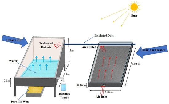
Figure 1.
Schematic View of Latent Heat Storage Based Single-Slope Solar Still Assisted with Solar Air Heater.
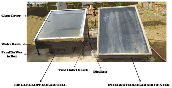
Figure 2.
Experimental View of Latent Heat Storage Based Single-Slope Solar Still Assisted with Solar Air Heater.
Table 2.
Technical specifications of instruments.
3. Numerical Analysis
3.1. Uncertainty Analysis
The uncertainties introduced by the instruments during the experimental measurements are investigated in this paper. Few values are considered from the datasheet for the instrument, while others are acquired from the instrument’s supplier. The uncertainties and errors of the experiment are calculated using Taylor’s methods [17,18,19]. The uncertainties of variables such as temperature and productivity are directly measured to account for both the random and systematic sources of inaccuracy. The uncertainty of δ value e, such as still efficiency, determined from the experimental results, is calculated using the following Equation [20].
where, δ2 and δ1 = the measured values of uncertainty y and x, respectively.
The above equation may be utilized for more than two measured values. By referring to this equation, the efficiency uncertainty is calculated to be 1.9%. Table 3 provides an illustration of the measured values of uncertainty.
3.2. Theoretical Analysis
The various heat transfer coefficients are:
= heat transfer coefficients for water surface and glass,
= heat transfer coefficient for glass and environment and
= heat transfer coefficient for water-basin lining [20].
= heat loss coefficient by evaporation from the water surface
The saturated partial pressure of glass is denoted by Pg, whereas Pw represents the saturated partial pressure of the water [6,7];
The evaporative heat transfer coefficient can be evaluated as follows:
While the hourly output of the solar still can be evaluated as:
The solar still’s overall thermal efficiency is the ratio between the evaporative heat transfer to the solar irradiation on the absorber plate and is calculated by the following equation.
3.3. Exergy Analysis
The exergy analysis function is derived from the second law of thermodynamics and acts as an indicator of the energy’s ability to convert into work. The exergy can be explained as the maximum work a system can produce when it approaches thermodynamic equilibrium in a particular environment. The general equation for the exergy balance is given below [7]:
The solar irradiance exergy is used to estimate the exergy input to the solar still as shown in below Equation (9):
where, Ts = 6000 K temperature of the Sun, Ex,s = input of exergy to the solar still from solar insulation, Ab = effective still basin area in m2, Additionally, the accumulated incident solar irradiance on solar still is measured in W/m2. For the still used in this work, Equation (10) shows the exergy output of the product, which here is distilled water.
where Ex,ev is the exergy due to evaporation, and λlt is the latent heat of evaporation.
where,
The exergy efficiency is calculated as the difference between the input and output exergy, and it is written as [8].
4. Result and Discussion
During the experiment, parameters such as the temperature of the glass cover, ambient temperature, the temperature of the basin, the PCM temperature, and solar radiation were recorded on an hourly basis. Additionally, the quantity of desalinated water was recorded hourly. On 7 April 2021, a comparison between three identical SSSS with latent heat storage and without latent heat storage was undertaken. Then, a second experiment was conducted between the optimum PCM percentage SSSS and a traditional solar still without PCM.
Solar radiation, ambient temperature, wind velocity, and relative humidity are plotted as a function of time, and they are shown in Figure 3a–d. It can be observed from the figure that the peak values of various dependent variables are 48 °C, 1.6 m/s, 68%, and 1350 W/m2, respectively.
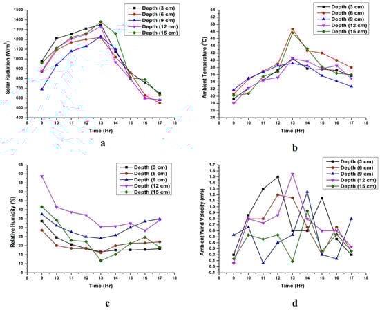
Figure 3.
(a–d) Variation of Solar radiation, Ambient temperature, Relative humidity, and Ambient wind velocity vs. time.
Figure 4a–e shows the variation in the water temperatures inside the still with respect to experiment time at different depths. The peak temperature of the water in the solar stills with 3 cm, 6 cm, 9 cm, 12 cm, and 15 cm depths are 65 °C, 57 °C, 55 °C, 56 °C, and 54 °C, respectively, for SSSS (LH) with SAH. It was observed that due to the release of thermal energy from PCM, the temperature of the water in the solar still with PCM remains constant, while the temperature in the solar still without PCM decreases at off-sunshine hours.
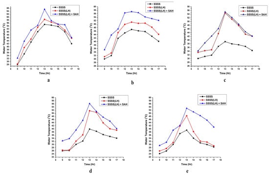
Figure 4.
(a–e) Variation of water temperature vs. time at the depth of 3 cm, 6 cm, 9 cm, 12 cm and 15 cm, respectively.
Figure 5a–e shows the glass temperature with respect to time during the experimentation. The peak temperatures can be recorded as 63 °C, 54 °C, 54 °C, 56 °C, and 55 °C for solar stills with depths of 3 cm, 6 cm, 9 cm, 12 cm, and 15 cm, respectively. Figure 6 shows the dependence of PCM (Paraffin wax) and SAH on the temperature of the proposed solar stills with respect to time. The SSSS (LH) with SAH between 9 a.m. and 2 p.m. shows higher temperatures with PCM in comparison to other solar still. Additionally, between 4 p.m. and 5 p.m., the temperature remains higher due to the release of heat from PCM.
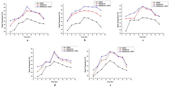
Figure 5.
(a–e) Variation of glass temperature vs. time at the depth of 3 cm, 6 cm, 9 cm, 12 cm, and 15 cm, respectively.
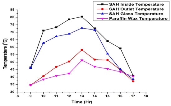
Figure 6.
Variation of SAH and Paraffin wax temperature vs. time.
The hourly freshwater productivity per m2 for three SSSS is shown in Figure 7a–e. It was observed that the hourly output of fresh water between 9 a.m. and 12 p.m. was higher for solar still having PCM with SAH in comparison to solar still without SAH. Additionally, the thermal energy stored in PCM provides higher output per hour between 12 p.m. and 5 p.m. in comparison to a solar still without PCM.
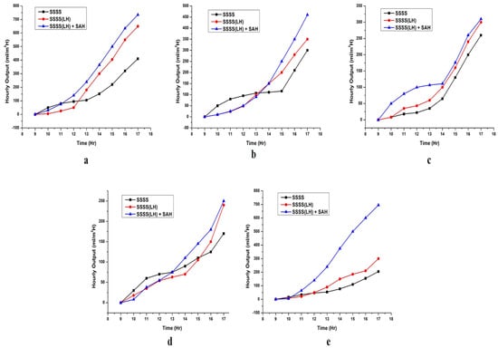
Figure 7.
(a–e) Variation of hourly output vs. time at the depth of 3 cm, 6 cm, 9 cm, 12 cm, and 15 cm, respectively.
Figure 8a–e shows the variation in the basin temperature as a function of time. It can be observed from the graph that the productivity of the solar still equipped with PCM and SAH was more in comparison to a conventional solar still. It is also observed that solar still productivity equipped with PCM increases between 1 p.m. and 5 p.m. from 18.6% to 27.7% due to the release of stored thermal energy by PCM, which increases the temperature difference between the distilled water and glass and ultimately attracts more vapor to condensate on the glass wall. Concluding from the above discussion, it is clear that the highest productive solar still is equipped with PCM and SAH. Another experiment is carried out to compare the solar still with PCM and a traditional solar still. The variation in the hourly productivity of freshwater per m2 from 9 a.m. to 2 p.m. was similar in both traditional SSSS and the still equipped with PCM. However, as discussed, due to the release of stored thermal energy by PCM, the productivity of freshwater was higher in the solar still equipped with PCM than conventional SSSS.
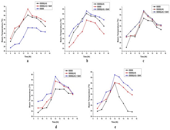
Figure 8.
(a–e) Variation of basin temperature vs. time at the depth of 3 cm, 6 cm, 9 cm, 12 cm, and 15 cm, respectively.
The Average Daily efficiency of all three solar stills was analyzed. The efficiency of the solar still with PCM and SAH is higher than the efficiency of the other two configured stills. The efficiency of the solar still with PCM and SAH was higher at 65.58% than conventional solar still efficiency. The efficiency for the solar still with PCM and SAH is 4.21% more than a solar still with PCM only. The exergy efficiency and solar still efficiency increases at higher water temperature. Additionally, few other parameters also affect exergy and efficiency, such as the temperature of the glass surface and the atmospheric temperature. The efficiency of all three solar stills at different depths is shown in Figure 9.
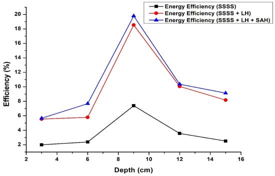
Figure 9.
Variation of efficiency at different depth.
The impact of the modifications to the system’s design and operational parameters on its exergy efficiency is covered in this section. The mass flow rate of the water, the quantity of PV/T collectors, the mass of the water in the basin, and the mass of the PCM were the design and operational parameters that were examined. In order to assess the irreversibility of the various system components and the exergy fractions, the desirable values for the design and operating parameters were established.
Relatively high exergy is seen due to solar irradiation. However, the same is not true for the exergy efficiency of a solar collector. Moreover, exergy efficiency improved with increases in the temperature of the solar collector. The highest increase in exergy efficiency was achieved at the highest temperature. Therefore, considering the economic aspect and increased costs, heat storage-based materials were considered for the system to provide a constant temperature. Table 3, Table 4, Table 5, Table 6 and Table 7 depict the daily exergy output and exergy efficiency. Equation (14) provides the daily exergies according to varying depths, as shown in Table 3, Table 4, Table 5, Table 6 and Table 7.
Table 3.
Exergy analysis of SSSS, SSSS (LH) and SSSS (LH + SAH) at the depth of 3 cm.
Table 4.
Exergy analysis of SSSS, SSSS (LH) and SSSS (LH + SAH) at the depth of 6 cm.
Table 5.
Exergy analysis of SSSS, SSSS (LH) and SSSS (LH + SAH) at the depth of 9 cm.
Table 6.
Exergy analysis of SSSS, SSSS (LH) and SSSS (LH + SAH) at the depth of 12 cm.
Table 7.
Exergy analysis of SSSS, SSSS (LH) and SSSS (LH + SAH) at the depth of 15 cm.
Table 3 depicts the hourly variation of Exin, Exout, and ᶯ for all types of solar still at a depth of 03 cm. The variation in Exin is 606.22–1258.44, 0–10.37 for Exout, and 0–1.71% for ᶯ for SSSS. Exin is found to be highest (1258.44) at 13.00 due to the highest ambient temperature during experimentation because Exin depends primarily on the ambient temperature. Exin was found to be lowest (606.22) at 17.00 p.m. due to the minimum ambient temperature. Exout was found to be highest at 17.00 (10.37) due to the high water condensation process inside the solar still. Since exergy efficiency is the ratio of Exout and Exin, the ratio of these two parameters is the highest (1.71%) at 17.00 and the lowest (0) at 9.00 a.m.
Similarly, the variation in Exin is 111.71–1139.6, 0–14.88 for Exout, and 0–13.33% for ᶯ SSSS (LH). Exin was found to be highest at 13.00 and lowest at 17.00. However, Exout was found to be highest at 17.00 (14.88) and lowest at 9.00 (0). Similarly, the exergy efficiency is highest at 17.00 (13.33%) and minimum at 9.00 (0%).
The variation in SSSS (LH + SAH) for Exin is 92.58–1161.24; 0–16.05 for Exout, and 0–17.33% for ᶯ. Exin was found to be the highest at 13.00 (1161.24) and lowest at 17.00 h (92.58). Exout was found to be highest at 17.00 h (16.05) and lowest at 9 a.m. (0). The exergy efficiency follows the same pattern as the exergy outlet. The exergy efficiency is highest at 17 h (17.38%) and zero at 9 a.m.
From a comparison of all three types of solar stills, it can be concluded that both Exout and ᶯ are found to be highest for SSSS (LH + SAH) due to the combined effect of LH and SAH and the lowest SSSS due to no additional effect.
Table 4 presents the exergy analysis of SSSS, SSSS (LH), and SSSS (LH + SAH) at 6 cm basin water depth. The variations in all parameters were found to be similar for the system performance at a depth of 3 cm. The exergy efficiency is found to be highest for SSSS (LH + SAH), i.e., 2.60%, and lowest for SSSS (1.18%).
Table 5, Table 6 and Table 7 represent the exergy analysis for all three systems at the basin water depth of 9 cm, 12 cm, and 15 cm. It follows the same trend as Table 3 and Table 4. The highest exergy efficiency for SSSS (LH + SAH) at a depth of 9 cm, 12 cm, and 15 cm are 1.46, 0.87, and 2.25, respectively. Additionally, the minimum exergy efficiency for SSSS (LH + SAH) at the depth of 9 cm, 12 cm, and 15 cm are 0.07, 0.02, and 0.03, respectively
From the above study, it is concluded that the highest ᶯ was obtained for all three systems at the 3 cm basin depth and lowest at 12 cm and 15 cm water depth, as the heat obtained at a depth of 3 cm is higher due to the presence of a lower amount of water in comparison to the depth of 12 cm and 15 cm.
The cost of the solar still was analyzed, as shown in Table 8. It was found that the maximum percentage of the cost was utilized in paraffin wax for the fabrication of the system, i.e., USD 50, while the minimum cost was utilized in the freshwater tank, i.e., USD 5. The total sum expended for fabricating the SSSS (SAH + LH) amounted to USD 224. The fabrication cost of the solar still, when compared to the other article, is high in heat storage based SSSS assisted with SAH because of the presence of solar air heater and paraffin wax as a phase change material. However, the heat storage material and assisted solar air heater provide constant heat throughout the desalination process.
Table 8.
Cost of Latent heat storage-based SS.
5. Conclusions
Two types of latent heat storage materials were used to increase the yield of SS. For both, the stills energy, exergy, and yield were analyzed. Additionally, an economic analysis was performed while concluding the investigation. After due investigation, it may be concluded that heat storing material, which in this case was paraffin wax, had a noticeable effect on the productivity and performance of SS. The important conclusions are summarized below:
- The efficiency of still with PCM and SAH was higher at 65.58% than a conventional still efficiency.
- The heat storage medium had sourced heat to the solar still in the absence of sunshine and provided a supplementary source of heat throughout the daytime.
- The definite shape of latent heat storage material in the cubical section is identified as one of the best techniques to augment production.
- The daily yield of the conventional still increased by 44% with respect to the conventional solar still.
- The average exergy efficiency of a single-slope solar still with latent heat storage coupled with a solar air heater is 83.19% higher than a traditional solar still.
- Since melting is a lengthier process than solidification, this allows the warm water to flow approximately at a constant temperature that is close to the melting point of PCM for a longer period.
- A slope of 23.34° was found optimum for the collector, as the yield collected at this slope was found to be maximum.
- As we know, for solar applications tilt angle is fixed. A better option is to keep the slope of the still at an angle close to the site’s latitude.
- The incident solar radiation on the still comprises much of the irreversibility caused due to the basin, water, and the absorbing plate of the solar collector.
Hence, from the above inferences, it is concluded that the utilization of a solar still with SAH and PCM as energy storage is a sustainable and viable choice for potable water production.
Author Contributions
Conceptualization, O.P.; methodology, S.K.; validation, S.K. And O.P.; formal analysis, O.P.; investigation, O.P.; data curation, S.K.; writing—original draft preparation, S.K.; writing—review and editing, O.P.; visualization, O.P.; supervision, O.P.; project administration, O.P.; funding acquisition, S.K. All authors have read and agreed to the published version of the manuscript.
Funding
This research received no external funding.
Data Availability Statement
All are original data taken from fabricated experimental setup.
Conflicts of Interest
The authors declare no conflict of interest.
References
- Durkaieswaran, P.; Murugavel, K.K. Various special designs of single basin passive solar still–A review. Renew. Sustain. Energy Rev. 2015, 49, 1048–1060. [Google Scholar] [CrossRef]
- Fathy, M.; Hassan, H.; Ahmed, M.S. Experimental study on the effect of coupling parabolic trough collector with double slope solar still on its performance. Sol. Energy 2018, 163, 54–61. [Google Scholar] [CrossRef]
- Prakash, O.; Ahmad, A.; Kumar, A.; Hasnain, S.M.; Kumar, G. Comprehensive Analysis of Design Software Application in Solar Distillation Units. Mater. Sci. Energy Technol. 2022, 5, 171–180. [Google Scholar] [CrossRef]
- Deshmukh, H.S.; Thombre, S.B. Solar distillation with single basin solar still using sensible heat storage materials. Desalination 2017, 410, 91–98. [Google Scholar] [CrossRef]
- Yousef, M.S.; Hassan, H.; Kodama, S.; Sekiguchi, H. An experimental study on the performance of single slope solar still integrated with a PCM-based pin-finned heat sink. Energy Procedia 2019, 156, 100–104. [Google Scholar] [CrossRef]
- Madiouli, J.; Lashin, A.; Shigidi, I.; Badruddin, I.A.; Kessentini, A. Experimental study and evaluation of single slope solar still combined with flat plate collector, parabolic trough and packed bed. Sol. Energy 2020, 196, 358–366. [Google Scholar] [CrossRef]
- Shanmugan, S.; Essa, F.A.; Gorjian, S.; Kabeel, A.E.; Sathyamurthy, R.; Manokar, A.M. Experimental study on single slope single basin solar still using TiO2 nano layer for natural clean water invention. J. Energy Storage 2020, 30, 101522. [Google Scholar] [CrossRef]
- Modi, K.V.; Shukla, D.L.; Ankoliya, D.B. A comparative performance study of double basin single slope solar still with and without using nanoparticles. J. Sol. Energy Eng. 2019, 141, 031008. [Google Scholar] [CrossRef]
- Estahbanati, M.R.K.; Ahsan, A.; Feilizadeh, M.; Jafarpur, K.; Ashrafmansouri, S.-S.; Feilizadeh, M. Theoretical and experimental investigation on internal reflectors in a single-slope solar still. Appl. Energy 2016, 165, 537–547. [Google Scholar] [CrossRef]
- Bazri, S.; Badruddin, I.A.; Naghavi, M.S.; Bahiraei, M. A review of numerical studies on solar collectors integrated with latent heat storage systems employing fins or nanoparticles. Renew. Energy 2018, 118, 761–778. [Google Scholar] [CrossRef]
- Beemkumar, N.; Karthikeyan, A.; Yuvarajan, D.; Lakshmi Sankar, S. Experimental Investigation on Improving the Heat Transfer of Cascaded Thermal Storage System Using Different Fins. Arab. J. Sci. Eng. 2017, 42, 2055–2065. [Google Scholar] [CrossRef]
- Hawlader, M.N.A.; Uddin, M.S.; Khin, M.M. Microencapsulated PCM thermal-energy storage system. Appl. Energy 2003, 74, 195–202. [Google Scholar] [CrossRef]
- Zhao, C.Y.; Lu, W.; Tian, Y. Heat transfer enhancement for thermal energy storage using metal foams embedded within phase change materials (PCMs). Sol. Energy 2010, 84, 1402–1412. [Google Scholar] [CrossRef]
- Khodadadi, J.M.; Hosseinizadeh, S.F. Nanoparticle-enhanced phase change materials (NEPCM) with great potential for improved thermal energy storage. Int. Commun. Heat Mass Transf. 2007, 34, 534–543. [Google Scholar] [CrossRef]
- Ahmad, A.; Prakash, O. Performance evaluation of a solar greenhouse dryer at different bed conditions under passive mode. J. Sol. Energy Eng. 2020, 142, 1–23. [Google Scholar] [CrossRef]
- Ahmad, A.; Prakash, O. Thermal analysis of north wall insulated greenhouse dryer at different bed conditions operating under natural convection mode. Environ. Prog. Sustain. Energy 2019, 38, e13257. [Google Scholar] [CrossRef]
- Ahmad, A.; Prakash, O.; Kumar, A. Drying kinetics and economic analysis of bitter gourd flakes drying inside hybrid greenhouse dryer. Environ. Sci. Pollut. Res. 2021, 1–15. [Google Scholar] [CrossRef] [PubMed]
- Ahmad, A.; Prakash, O.; Kumar, A.; Hasnain, S.M.; Verma, P.; Zare, A.; Dwivedi, G.; Pandey, A. Dynamic analysis of daylight factor, thermal comfort and energy performance under clear sky conditions for building: An experimental validation. Mater. Sci. Energy Technol. 2022, 5, 52–65. [Google Scholar] [CrossRef]
- Prakash, O.; Bhushan, B.; Kumar, A.; Ahmed, A. Thermal analysis of domestic type single slope–basin solar still under two different water depths. Mater. Today Proc. 2021, 46, 5482–5489. [Google Scholar] [CrossRef]
- Kabeel, A.E.; El-Agouz, E.-S.; Athikesavan, M.M.; Duraisamy Ramalingam, R.; Sathyamurthy, R.; Prakash, N.; Prasad, C. Comparative analysis on freshwater yield from conventional basin-type single slope solar still with cement-coated red bricks: An experimental approach. Environ. Sci. Pollut. Res. 2020, 27, 32218–32228. [Google Scholar] [CrossRef] [PubMed]
Publisher’s Note: MDPI stays neutral with regard to jurisdictional claims in published maps and institutional affiliations. |
© 2022 by the authors. Licensee MDPI, Basel, Switzerland. This article is an open access article distributed under the terms and conditions of the Creative Commons Attribution (CC BY) license (https://creativecommons.org/licenses/by/4.0/).