

Analysis of Electromagnetic–Mechanical Characteristics according to Shaft Materials of Permanent Magnet Synchronous Motor
Abstract
:1. Introduction
2. Comparison of Electromagnetic Characteristics according to Shaft Materials
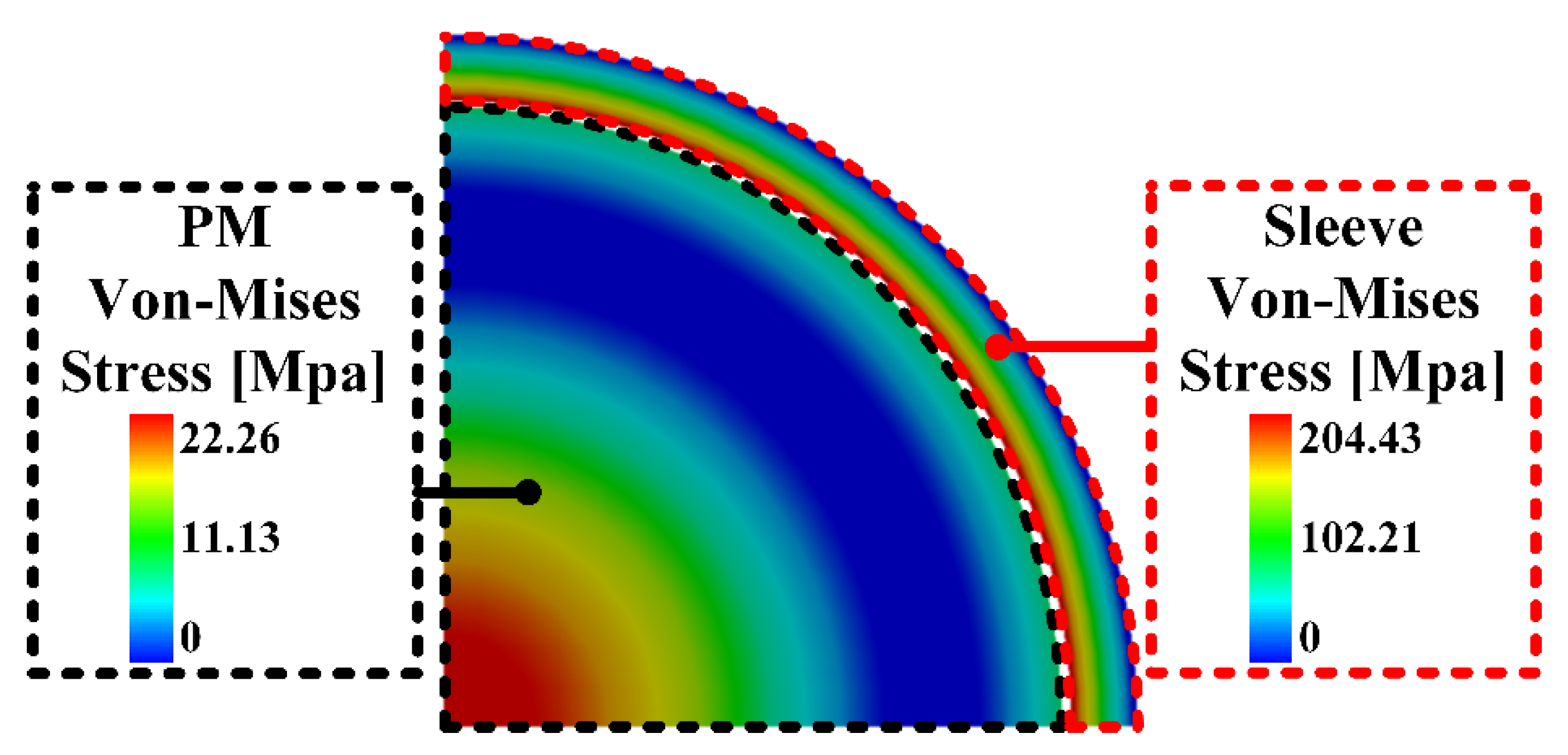
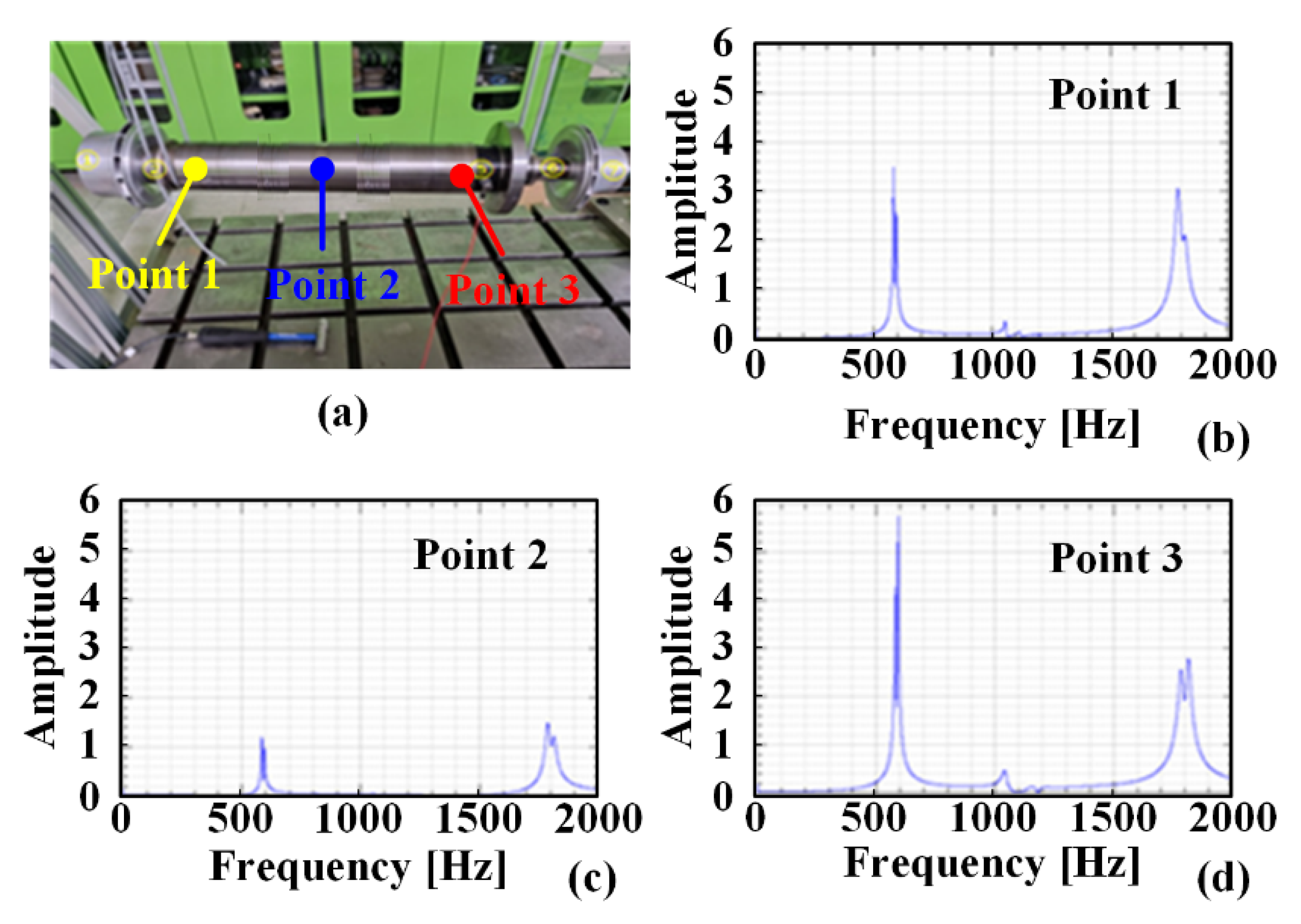
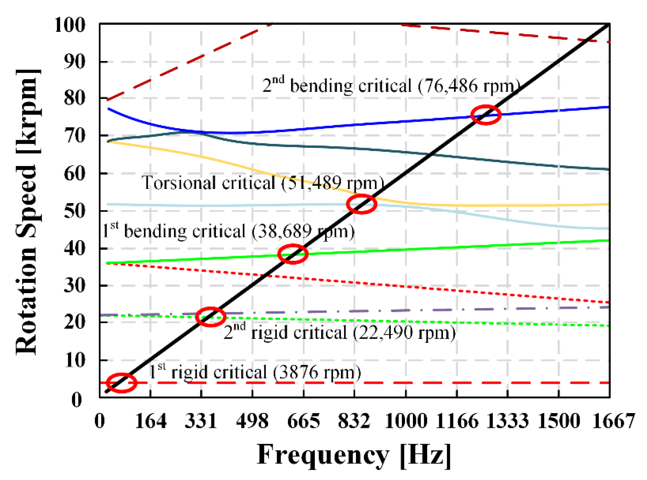
3. Comparison of Mechanical Characteristics according to Shaft Materials
4. Conclusions
Author Contributions
Funding
Data Availability Statement
Conflicts of Interest
References
- Jing, L.; Tang, W.; Wang, T.; Ben, T.; Qu, R. Performance Analysis of Magnetically Geared Permanent Magnet Brushless Motor for Hybrid Electric Vehicles. IEEE Trans. Transp. Electrif. 2022, 8, 2874–2883. [Google Scholar] [CrossRef]
- Paul, S.; Chang, J. Fast Model-Based Design of High Performance Permanent Magnet Machine for Next Generation Electric Propulsion for Urban Aerial Vehicle Application. CES Trans. Electr. Mach. Syst. 2021, 5, 143–151. [Google Scholar] [CrossRef]
- Lee, Y.H.; Hsieh, M.F.; Chen, P.H. A Novel Variable Flux Spoke Type Permanent Magnet Motor with Swiveling Magnetization for Electric Vehicles. IEEE Access 2022, 10, 62194–62209. [Google Scholar] [CrossRef]
- Mahmouditabar, F.; Vahedi, A.; Takorabet, N. Design and Analysis of Interior Permanent Magnet Motor for Electric Vehicle Application Considering Irreversible Demagnetization. IEEE Trans. Ind. Appl. 2022, 58, 284–293. [Google Scholar] [CrossRef]
- Sun, X.; Shi, Z.; Cai, Y.; Lei, G.; Guo, Y.; Zhu, J. Driving-Cycle-Oriented Design Optimization of a Permanent Magnet Hub Motor Drive System for a Four-Wheel-Drive Electric Vehicle. IEEE Trans. Transp. Electrif. 2020, 6, 1115–1125. [Google Scholar] [CrossRef]
- Li, W.; Cao, Z.; Zhang, X. Thermal Analysis of the Solid Rotor Permanent Magnet Synchronous Motors With Air-Cooled Hybrid Ventilation Systems. IEEE Trans. Ind. Electron. 2022, 69, 1146–1156. [Google Scholar] [CrossRef]
- Xu, Y.; Ai, M.; Xu, Z.; Liu, W.; Wang, Y. Research On Interior Permanent Magnet Synchronous Motor Based on Performance Matching of Electric Bus. IEEE Trans. Appl. Supercond. 2021, 31, 5204304. [Google Scholar] [CrossRef]
- Tak, B.-O.; Ro, J.-S. Analysis and Design of an Axial Flux Permanent Magnet Motor for in-Wheel System Using a Novel Analytical Method Combined With a Numerical Method. IEEE Access 2020, 8, 203994–204011. [Google Scholar] [CrossRef]
- Dong, B.; Wang, K.; Han, B.; Zheng, S. Thermal Analysis and Experimental Validation of a 30 kW 60000 r/min High-Speed Permanent Magnet Motor With Magnetic Bearings. IEEE Access 2019, 7, 92184–92192. [Google Scholar] [CrossRef]
- Zhang, C.; Chen, L.; Wang, X.; Tang, R. Loss Calculation and Thermal Analysis for High-Speed Permanent Magnet Synchronous Machines. IEEE Access 2020, 8, 92627–92636. [Google Scholar] [CrossRef]
- Liu, Z.; Chiba, A.; Irino, Y.; Nakazawa, Y. Optimum Pole Number Combination of a Buried Permanent Magnet Bearingless Motor and Test Results at an Output of 60 kW With a Speed of 37000 r/min. IEEE Open J. Ind. Appl. 2020, 1, 33–41. [Google Scholar] [CrossRef]
- Cheng, X.; Xu, W.; Du, G.; Zeng, G.; Zhu, J. Novel rotors with low eddy current loss for high speed permanent magnet machines. CES Trans. Electr. Mach. Syst. 2019, 3, 187–194. [Google Scholar] [CrossRef]
- Bhuiyan, N.A.; McDonald, A. Optimization of Offshore Direct Drive Wind Turbine Generator With Consideration of Permanent Magnet Grade and Temperature. IEEE Trans. Energy Convers. 2018, 34, 1105–1114. [Google Scholar] [CrossRef] [Green Version]
- Gerada, D.; Huang, X.; Zhang, C.; Zhang, H.; Zhang, X.; Gerada, C. Electrical Machines for Automotive Electrically Assisted Turbocharging. IEEE/ASME Trans. Mechatron. 2018, 23, 2054–2065. [Google Scholar] [CrossRef]
- Wu, S.; Tong, W.; Li, W.; Yu, S.; Tang, R. Electromagnetic Vibration Analysis of High-Speed Permanent Magnet Synchronous Machines With Amorphous Metal Stator Cores Considering Current Harmonics. IEEE Trans. Ind. Electron. 2020, 67, 10156–10167. [Google Scholar] [CrossRef]
- Zhang, Z.; Deng, Z.; Sun, Q.; Peng, C.; Gu, Y.; Pang, G. Analytical Modeling and Experimental Validation of Rotor Harmonic Eddy-Current Loss in High-Speed Surface-Mounted Permanent Magnet Motors. IEEE Trans. Magn. 2019, 55, 8100811. [Google Scholar] [CrossRef]
- Lee, J.-I.; Shin, K.-H.; Bang, T.-K.; Choi, B.-S.; Kim, B.-O.; Choi, J.-Y. Experiments and Design Criteria for a High-Speed Permanent Magnet Synchronous Generator With Magnetic Bearing Considering Mechanical Aspects. IEEE Trans. Appl. Supercond. 2020, 30, 5204205. [Google Scholar] [CrossRef]
- Qiu, H.; Tang, B.; Yu, W.; Yuan, S.; Wu, J.; Yang, C.; Cui, G. Analysis of the super high-speed permanent magnet generator under unbalanced load condition. IET Electr. Power Appl. 2017, 11, 1492–1498. [Google Scholar] [CrossRef]
- Zhang, Y.; McLoone, S.; Cao, W.; Qiu, F.; Gerada, C. Power Loss and Thermal Analysis of a MW High-Speed Permanent Magnet Synchronous Machine. IEEE Trans. Energy Convers. 2017, 32, 1468–1478. [Google Scholar] [CrossRef] [Green Version]
- Jang, S.-M.; Ko, K.-J.; Cho, H.-W.; Choi, J.-Y. Electromechanical Parameters Calculation of Permanent Magnet Synchronous Motor Using the Transfer Relations Theorem. IEEE Trans. Magn. 2007, 43, 2495–2497. [Google Scholar] [CrossRef]
- Ahn, J.-H.; Han, C.; Kim, C.-W.; Choi, J.-Y. Rotor Design of High-Speed Permanent Magnet Synchronous Motors Considering Rotor Magnet and Sleeve Materials. IEEE Trans. Appl. Supercond. 2018, 28, 5201504. [Google Scholar] [CrossRef]
- Jang, G.-H.; Ahn, J.-H.; Kim, B.-O.; Lee, D.-H.; Bang, J.-S.; Choi, J.-Y. Design and Characteristic Analysis of a High-Speed Permanent Magnet Synchronous Motor Considering the Mechanical Structure for High-Speed and High-Head Centrifugal Pumps. IEEE Trans. Magn. 2018, 54, 8204906. [Google Scholar] [CrossRef]
- Ou, J.; Liu, Y.; Breining, P.; Gietzelt, T.; Wunsch, T.; Doppelbauer, M. Experimental Characterization and Feasibility Study on High Mechanical Strength Electrical Steels for High-Speed Motors Application. IEEE Trans. Ind. Appl. 2021, 57, 284–293. [Google Scholar] [CrossRef]
- Shin, K.-H.; Bang, T.-K.; Cho, H.-W.; Choi, J.-Y. Design and Analysis of High-Speed Permanent Magnet Synchronous Generator With Rotor Structure Considering Electromechanical Characteristics. IEEE Trans. Appl. Supercond. 2020, 30, 5204305. [Google Scholar] [CrossRef]
- Lee, J.-I.; Bang, T.-K.; Lee, H.-K.; Woo, J.-H.; Nah, J.; Choi, J.-Y. Design of the High-Speed PMSG with Two Different Shaft Material Considering Overhang Effect and Mechanical Characteristics. Appl. Sci. 2021, 11, 7670. [Google Scholar] [CrossRef]
- Shin, K.-H.; Jung, K.-H.; Cho, H.-W.; Choi, J.-Y. Analytical Modeling and Experimental Verification for Electromagnetic Analysis of Tubular Linear Synchronous Machines With Axially Magnetized Permanent Magnets and Flux-Passing Iron Poles. IEEE Trans. Magn. 2018, 54, 8204006. [Google Scholar] [CrossRef]
- Zhang, F.; Du, G.; Wang, T.; Liu, G.; Cao, W. Rotor Retaining Sleeve Design for a 1.12-MW High-Speed PM Machine. IEEE Trans. Ind. Appl. 2015, 51, 3675–3685. [Google Scholar] [CrossRef] [Green Version]
- Zheng, J.; Zhao, W.; Ji, J.; Zhu, J.; Lee, C.H.T. Sleeve design of permanent-magnet machine for low rotor losses. IEEE Chinese Journal of Electrical Engineering. 2020, 6, 86–96. [Google Scholar] [CrossRef]
- Han, T.; Wang, Y.-C.; Shen, J.-X. Analysis and Experiment Method of Influence of Retaining Sleeve Structures and Materials on Rotor Eddy Current Loss in High-Speed PM Motors. IEEE Trans. Ind. Appl. 2020, 56, 4889–4895. [Google Scholar] [CrossRef]
- Zhu, Z.; Huang, Y.; Dong, J.; Peng, F.; Yao, Y. Rotor Eddy Current Loss Reduction With Permeable Retaining Sleeve for Permanent Magnet Synchronous Machine. IEEE Trans. Energy Convers. 2020, 35, 1088–1097. [Google Scholar] [CrossRef]
- Zhang, H.; Zhang, X.; Gerada, C.; Galea, M.; Gerada, D.; Li, J. Design Considerations for the Tooth Shoe Shape for High-Speed Permanent Magnet Generators. IEEE Trans. Magn. 2015, 51, 8112904. [Google Scholar] [CrossRef]
- Woo, J.-H.; Bang, T.-K.; Kim, C.-W.; Yoon, I.-J.; Choi, J.-Y. Experimental and comparative study of mechanical and electromagnetic aspects of a high-speed permanent magnetic motor with two different magnetic materials. AIP Adv. 2020, 10, 015217. [Google Scholar] [CrossRef]
- Cho, H.-W.; Ko, K.-J.; Choi, J.-Y.; Shin, H.-J.; Jang, S.-M. Rotor Natural Frequency in High-Speed Permanent-Magnet Synchronous Motor for Turbo-Compressor Application. IEEE Trans. Magn. 2011, 47, 4258–4261. [Google Scholar] [CrossRef]
- Bang, T.-K.; Shin, K.-H.; Lee, J.-I.; Woo, J.-H.; Cho, H.-W.; Choi, J.-Y. Design of high-speed permanent magnet synchronous machines considering thermal demagnetization and mechanical characteristic of permanent magnet. AIP Adv. 2021, 11, 025129. [Google Scholar] [CrossRef]
- Huang, Z.; Fang, J. Multiphysics Design and Optimization of High-Speed Permanent-Magnet Electrical Machines for Air Blower Applications. IEEE Trans. Ind. Electron. 2016, 63, 2766–2774. [Google Scholar] [CrossRef]
- Fang, H.; Qu, R.; Li, J.; Zheng, P.; Fan, X. Rotor Design for High-Speed High-Power Permanent-Magnet Synchronous Machines. IEEE Trans. Ind. Appl. 2017, 53, 3411–3419. [Google Scholar] [CrossRef]
- Ede, J.; Zhu, Z.; Howe, D. Rotor resonances of high-speed permanent-magnet brushless machines. IEEE Trans. Ind. Appl. 2002, 38, 1542–1548. [Google Scholar] [CrossRef]


| Parameters | Value | Unit |
|---|---|---|
| Rated power | 145 | kW |
| Rated speed | 28,000 | rpm |
| Current density | 10–12 | A/mm2 |
| Operation temperature | 100 | °C |
| Outer diameter of rotor | 85 | mm |
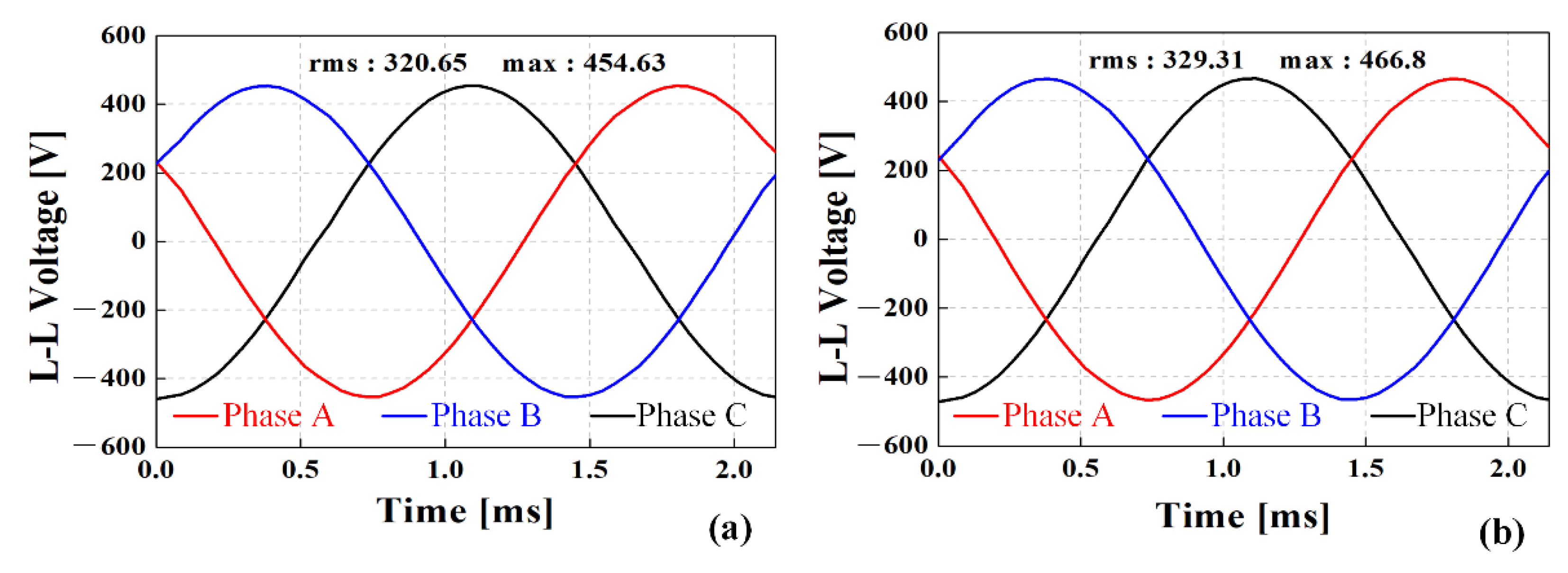
| Line-to-line back-EMF | 330 | Vrms |
| Parameters | SCM440 | Titanium |
|---|---|---|
| Self-inductance (μH) | 157.03 | 131.56 |
| Mutual inductance (μH) | 35.92 | 23.55 |
| Synchronous inductance (μH) | 192.95 | 155.11 |
| Parameters | SCM440 | Titanium |
|---|---|---|
| Output power (kW) | 145.1 | 145.7 |
| Current (Arms) | 270 | 260 |
| Torque (Nm) | 49.5 | 49.7 |
| Core loss (W) | 858.3 | 790.2 |
| Eddy current loss (W) | 298.8 | 289.6 |
| Copper loss (kW) | 1.95 | 1.81 |
| Current density (A/mm2) | 9.76 | 9.4 |
| Efficiency (%) | 97.9 | 98.05 |
| Materials | Yield Strength (MPa) | Poisson’s Ratio | Cost (kg/USD) |
|---|---|---|---|
| SCM440 | 830 | 0.284 | 2.71 |
| Titanium | 1100 | 0.33 | 38.46 |
| Materials | Sleeve Titanium | PM Sm2Co17 | |
| Parameters | |||
| Density (kg/m3) | 4430 | 8400 | |
| Poisson’s ratio | 0.33 | 0.24 | |
| Young’s modulus (Gpa) | 1.14 | 120 | |
| Yield strength (MPa) | 1100 | 35 | |
| Parameters | Value | Unit |
|---|---|---|
| Outer diameter of stator | 210 | mm |
| Outer diameter of rotor | 85 | mm |
| Thickness of sleeve | 4 | mm |
| Air gap length | 1.8 | mm |
| Axial length | 84 | mm |
Publisher’s Note: MDPI stays neutral with regard to jurisdictional claims in published maps and institutional affiliations. |
© 2022 by the authors. Licensee MDPI, Basel, Switzerland. This article is an open access article distributed under the terms and conditions of the Creative Commons Attribution (CC BY) license (https://creativecommons.org/licenses/by/4.0/).
Share and Cite
Lee, J.-I.; Kim, Y.-C.; Choi, J.-Y.; Cho, H.-W. Analysis of Electromagnetic–Mechanical Characteristics according to Shaft Materials of Permanent Magnet Synchronous Motor. Energies 2022, 15, 8046. https://doi.org/10.3390/en15218046
Lee J-I, Kim Y-C, Choi J-Y, Cho H-W. Analysis of Electromagnetic–Mechanical Characteristics according to Shaft Materials of Permanent Magnet Synchronous Motor. Energies. 2022; 15(21):8046. https://doi.org/10.3390/en15218046
Chicago/Turabian StyleLee, Jeong-In, Young-Cheol Kim, Jang-Young Choi, and Han-Wook Cho. 2022. "Analysis of Electromagnetic–Mechanical Characteristics according to Shaft Materials of Permanent Magnet Synchronous Motor" Energies 15, no. 21: 8046. https://doi.org/10.3390/en15218046