Article

Study on the Slurry Diffusion Law of Fluidized Filling Gangue in the Caving Goaf of Thick Coal Seam Fully Mechanized Caving Mining

1
College of Energy Science and Engineering, Xi’an University of Science and Technology, Xi’an 710054, China
2
Shaanxi Coal and Chemical Industry Technology Research Institute Co., Ltd., Xi’an 710100, China
3
The National Joint Engineering Research Center of the Green, Safe and Efficient Coal Mining, Xi’an 710065, China
4
Shaanxi Shanmei Hancheng Mining Co., Ltd., Hancheng 715400, China
*
Authors to whom correspondence should be addressed.
Energies 2022, 15(21), 8164; https://doi.org/10.3390/en15218164
Submission received: 22 September 2022 / Revised: 25 October 2022 / Accepted: 29 October 2022 / Published: 1 November 2022
(This article belongs to the Special Issue Advances in Coal and Water Co-mining)

Abstract

:
Because of the problem of gangue discharge and surface subsidence during coal mining, the current research on underground filling mainly focuses on the paste filling, solid filling, and grouting filling of the overburden separation layer after scaffolding. We proposed the technology of fluidization gangue grouting for filling the collapse area based on our previous research. The prediction method of residual space in the collapse area and the diffusion law of gangue fluidization filling slurry are two essential points for successfully implementing the technology and maximizing the use of goaf for gangue backfilling and reducing overburden settlement. To further explore the remaining space distribution law of the collapsed goaf in thick seam fully mechanized top coal caving mining and the effect of coal gangue fluidization filling, the caving goaf of the 3307 fully mechanized top coal caving face in Sangshuping No. 2 coal mine in the Weibei mining area was detected by the transient electromagnetic method. We studied the distribution law of the measured abnormal area in the caving goaf, which reflects the distribution law of the remaining space from one aspect. The coefficient of the remaining space was calculated to be 19.5%. Then, we applied COMSOL simulation software. The diffusion law of coal gangue fluidized slurry in the caving goaf was simulated and analyzed. It shows that the most obvious diffusion direction of the coal gangue slurry is the trend of the gradual expansion of the “cavity pore” multi-type residual space, indicating that with the increase in the diffusion distance, the diffusion resistance gradually increases, and the slurry morphology gradually presents the “claw” form. According to the space theory and fractal dimension theory, the prediction method of the remaining space in the caving goaf is given, and the design basis of the filling drilling parameters is determined. Finally, the field-filling test was carried out. The results show that the high- and low-level fluidized filling in the caving goaf can safely and efficiently handle the gangue in the mine, and the residual space characteristics and slurry diffusion law in the caving goaf are consistent with the above. The research results provide theoretical support for the fluidization filling technology of coal gangue in thick seam fully mechanized top coal caving areas.

1. Introduction

Coal accounts for approximately 26.5% of the world’s primary energy consumption. In the energy market of developing countries and regions in Asia, coal is the main resource. China, for example, produced 4.13 billion tons of raw coal in 2021, up 5.7% from the previous year. Large-scale mining of coal resources causes surface subsidence, soil erosion, damage to surface buildings, and a large amount of solid waste of coal gangue [1,2]. In recent years, China has accumulated more than 4.5 billion tons of coal gangue piles, forming more than 2600 coal gangue mountains, covering an area of 13,000 hectares. The casual landfilling or disordered heaping of coal gangue not only occupies vast land resources, but also triggers a series of environmental threats, such as soil deterioration, geological disaster, and leaching and diffusion of heavy metal ions into underground water [3]. Even worse, massive coal gangue dumps are inclined to suffer spontaneous combustion and release toxic gas consisting of SO2, CO, NOx, H2S, etc. [4], arising from a continuous heat generation by exothermic oxidations of pyrite (FeS2), unburnt coal, and organic matter when exposed to the atmosphere [5], and these pose a continuous hidden danger to people’s lives and their environment [6,7]. Thereby, the disposal of coal gangue waste has become a worldwide concern, especially in China.
At present, domestic and foreign scholars have organically combined gangue underground treatment with coal mining methods, forming a variety of coal filling methods such as comprehensive mechanized solid filling [8], paste filling [9], and overburden separation grouting filling [10,11], which have effectively solved the problem of water resource losses in mining area caused by gangue discharge and overburden subsidence [12]. However, the current filling method has higher requirements in terms of filling equipment and material properties, which leads to an increase in filling cost. In addition, the filling process of mining with filling and the combination of mining and filling is relatively complex, which makes the application and promotion of the current filling technology more difficult [13]. With the increase in mining depth, the availability of grouting and filling technology in overlying strata also decreases.
The fluidized filling technology of goaf coal gangue is mainly aimed at treating coal gangue, and the method is a new technology of filling by simply cementing the broken gangue or directly adding water to the pulping pump and filling it into the goaf underground. Compared with the traditional paste-filling method, the filling technology is simple, the material preparation is simple, and the investment is small. This technology has a broad application prospect in low-cost scale treatment of gangue, reduction of over-burden subsidence, and protection of water resources in mining areas [14,15].
The caving goaf is formed after the overburden above the goaf caves; it includes irregular rock mass, rock block, and the void formed by the caving. In the application process of gangue fluidization backfilling technology in a goaf, the study of residual space size, shape, and slurry diffusion law of the caving goaf is an essential point for the smooth implementation of gangue fluidization backfilling technology and guarantees the filling effect. Given such problems, some scholars at home and abroad have done much research on the subsidence law of overlying strata in stopes [16]; the fracture morphology of overlying strata in caving goaves [17,18]; and the law of crushing, swelling, and compaction of fractured rock mass by using similar material simulation and numerical simulation methods [19,20]. For example, Qian et al. [21] showed that the overburden fracture in the caving goaf would form an “O” ring pattern. Guo et al. [22] proposed four structural types of fractured rock mass in an old goaf and pointed out the inhomogeneity of pore distribution in the fractured rock mass. In addition, some scholars have made the latest progress in the ratio of coal gangue slurry, slurry flow transport, and mechanical properties, as well as the permeability law of slurry in rock mass fractures [23,24]. The free diffusion of slurry in the goaf under different flow conditions and the influencing factors of the diffusion state have been analyzed [25,26]. More importantly, the coal mining technology of gangue filling has a good effect in reducing the development of cracks in the overlying strata and protecting the surface and groundwater resources in the mining area [27,28].
Until now, great achievements have made been in coal gangue filling mining technology in the field of the mining industry, but the mechanism of coal gangue fluidized goaf filling technology still needs further study; in particular, the study of the goaf caving with residual space calculation method and gangue slurry in the diffusion rule of the caving zone will provide theoretical support for the application of coal gangue fluidized packing technology. In Section 2, the residual space of the 3307 caving goaf is presented. In Section 3, the diffusion law of slurry in a caving goaf under different conditions is studied. Section 4 presents the results of an industrial test carried out on the filling process of convective gangue. The fifth part summarizes the conclusion of this study.
To carry out the fluidized filling of gangue in the caving goaf to realize green mining, this paper studies the residual space in the caving goaf and the diffusion law of gangue slurry and presents the results of an industrial test implemented in Sangshuping No. 2 coal mine, providing technical support for the fluidized filling of gangue in the caving goaf.

2. Measurement of Residual Spatial Distribution in the Caving Goaf

2.1. Layout of Measuring Points

The coal mine stratum is usually continuously deposited, and its resistivity is generally stable or continuously changing in the transverse direction. When the coal mine stratum collapses due to the influence of mining, there will be relatively complete coal pillars, goaf filled with water, goaf not filled with water, and three other areas. The original stable and continuous apparent resistivity characteristics will be broken, showing the different characteristics of local relative high resistance, low resistance, or high resistance. This kind of stratum electrical difference will provide a good geophysical premise for the application of the transient electromagnetic method in detecting goaf. Therefore, the transient electromagnetic method was selected to measure the caving goaf of the 3307 working face of the Sangshuping No. 2 coal mine in the Weibei mining area [29,30,31].
The mining of this working face has been completed, and the collapse of the goaf tends to be stable. Through field survey and actual terrain conditions, 21 transient electromagnetic main survey lines were designed on the 3307 working face, and 23 side survey lines were arranged near the main survey line. There were a total of 44 transient electromagnetic survey lines and a total of 1806 brief electromagnetic physical points. The FCTEM100-1 towed high-resolution transient electromagnetic system was used for detection. The detection diameter was set according to D = H/10, and the actual detection total area was 40,484.5m2. The surface survey line layout and detection range are shown in Figure 1.

2.2. Exploration Results and Analysis

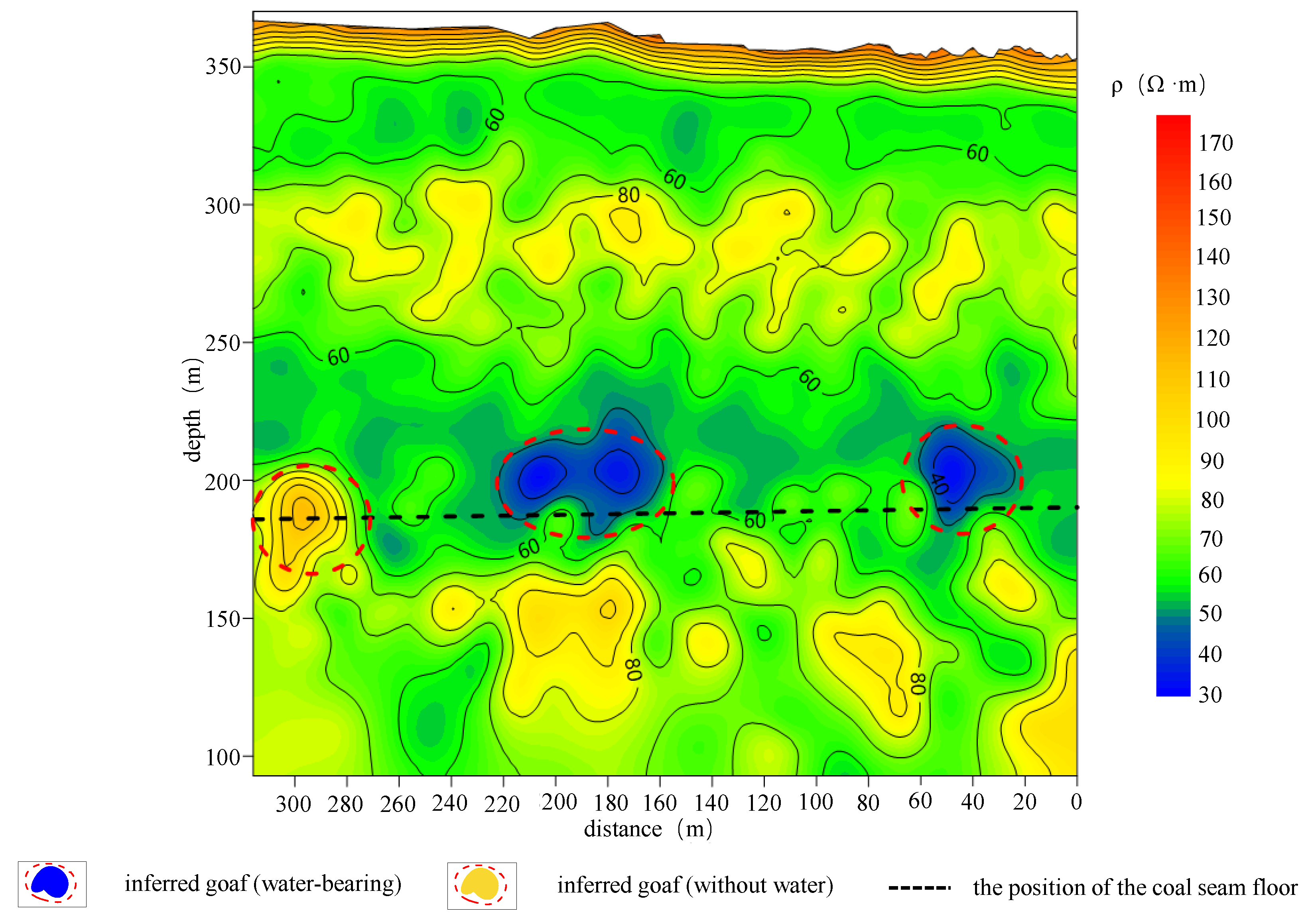
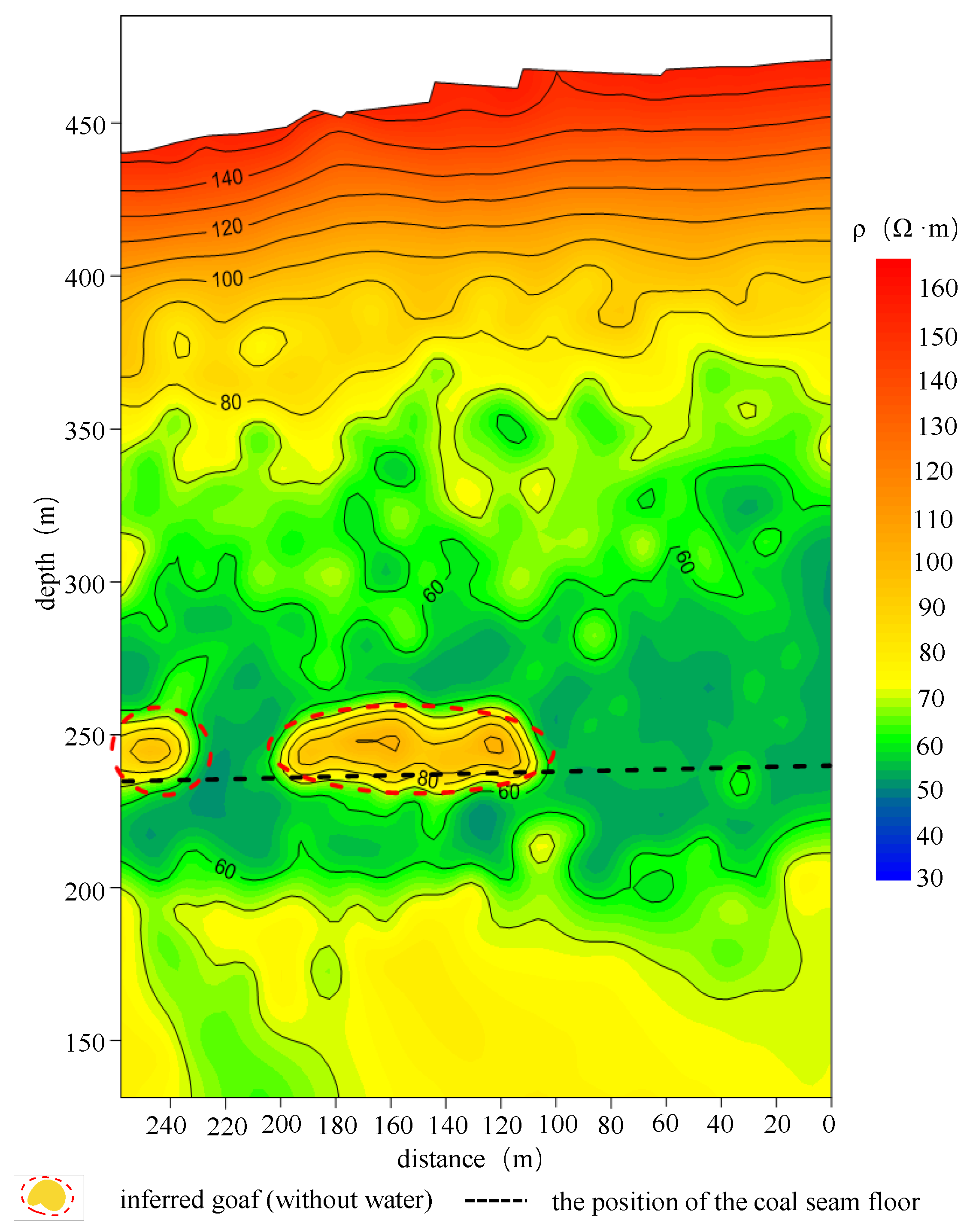
The apparent resistivity cross-section results were obtained for all transient electromagnetic survey lines (TMP-Z1~TMP-Z21, TMP-P1~TMP-P23) in the detection area. The results of the transient electromagnetic apparent resistivity of the survey lines TMP-Z14 and TMP-Z19 are shown in Figure 2 and Figure 3.
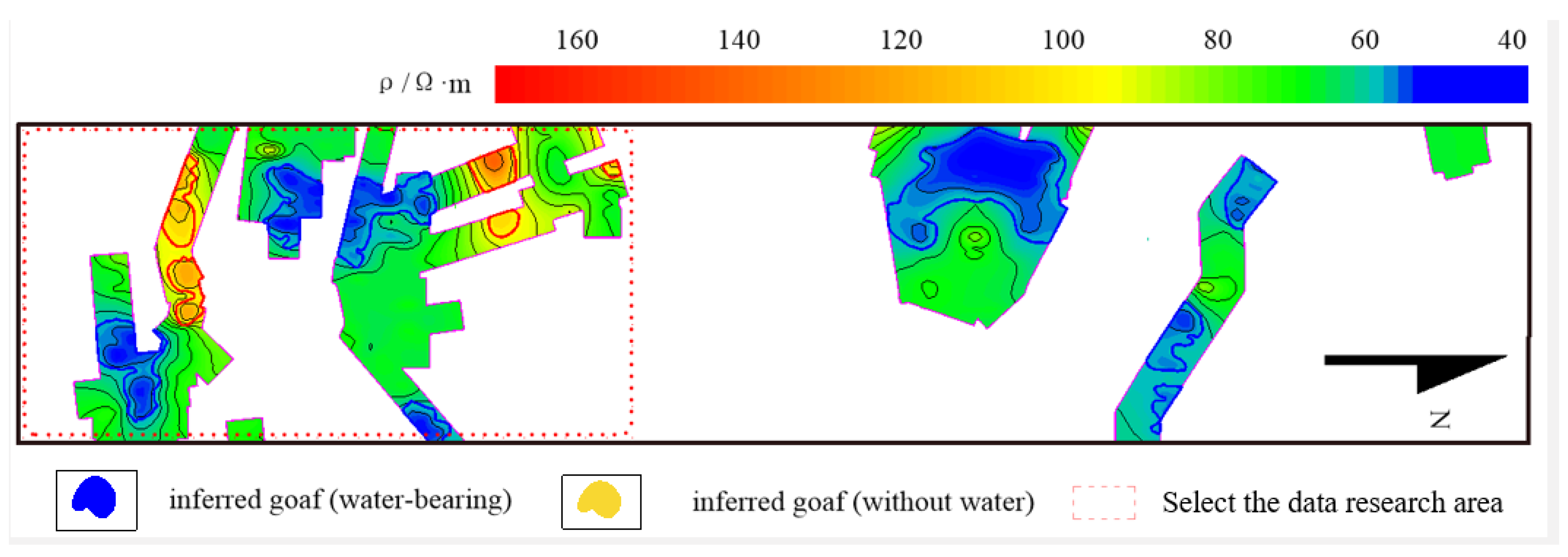
The evident resistivity values of all measuring points at 250 m elevation were extracted, and the noticeable resistivity slice results at 250 m depth of the working face were drawn according to the total detection range, as shown in Figure 4. The 3307 working face geological interpretation floor plan is shown in Figure 5. For the detection principle and detection equipment of the transient electromagnetic method, and in the process of interpretation of results, this paper will not repeat the anomaly identification features of Quaternary overburden, bedrock, coal, water-bearing voids, and non-aqueous voids.
According to the above distribution law of abnormal area, the roof caving form of goaf shows the principle of empty on both sides and dense center, and the shape conforms to the distribution law of the “O” ring. The residual space in the caving goaf is mainly concentrated on both sides of the gateway, and most of them are hollow. The actual detected residual space in the caving goaf accounts for 23.5% of the entire study area. The distribution law of the above-mentioned abnormal areas also represents the accumulation state of caving rocks at different positions in the caving goaf. The void-type residual space is mainly in a natural caving state without compaction, and the bulking factor is relatively significant, generally between 1.2 and 1.65. However, this coefficient will not cause the caving rock to fill the goaf under normal circumstances, so there will still be a specific space between the caving zone and the bedrock interface. The formula for calculating the stay height hv of this space is as follows [32]:
h v = h h w n 1 γ
In the above formula, h is the mining height, 6 m; hw is the direct roof caving height, taking the average value of 4m; n is the caving zone bulking factor, taking the value of 1.45; γ is the residual factor, which is related to the lithology and mining method of the caving rock, and is taken as 1.3 here. The stagnant height of the goaf of the mining face is calculated as 1.17 m. The residual coefficient of goaf is characterized by the ratio of the residual space of goaf to the theoretical space of goaf, the residual space coefficient is calculated to be 19.5%.

3. Numerical Simulation Test on the Diffusion Law of Gangue Slurry in Caving Goaf

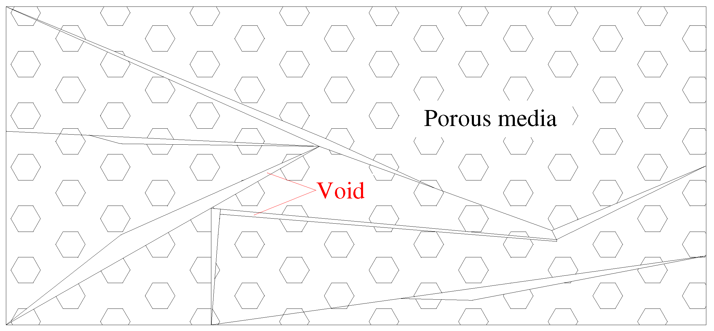
In terms of grouting in the caving zone, there are mainly porous medium theory, equivalent continuous medium theory, discrete fracture network medium theory, and fracture–pore dual-medium theory. In terms of grouting in the caving zone, there are mainly porous medium theory, equivalent continuous medium theory, discrete fracture network medium theory, and fracture–pore dual-medium theory. The dual-medium theory is the most widely used in slurry; it objectively reflects the seepage mechanism of fractured rock mass and is more suitable for problems in regions with large spatial and temporal scales [33,34,35]. The schematic diagram of the porous medium and fracture model is shown in Figure 6 below.
Based on the actual situation of gangue caving in the caving goaf and the dual-medium theory, the COMSOL simulation software [36,37,38] was used to simulate and analyze the slurry diffusion law within 200 m around the pipeline with the pipeline position as the center. The basic assumptions are as follows:
(1)
The slurry is a homogeneous, isotropic, incompressible fluid, and the flow pattern remains unchanged during motion.
(2)
The fissures are distributed horizontally, the opening of the gap remains unchanged, and the rock mass on both sides of the crack is an isotropic porous medium.
(3)
The fissure network cuts the rock mass, and the fissures have strong water conductivity.
(4)
Neglecting the influence of the partial flow of the grout perpendicular to the crack on the grout crack flow, it is considered that the grout in the crack is centered on the grouting hole and diffuses in a radial circle, and the flow direction is parallel to the crack surface.
(5)
The influence of the slurry flow on the mechanical properties of the surrounding rock mass is ignored, and the surrounding rock structure and geometric characteristics remain unchanged.
The slurry can be regarded as a Newtonian fluid, and the slurry constitutive equation based on the Newtonian fluid is as follows:
τ = μ t γ
where τ is the fluid shear stress, μ t is the liquid viscosity coefficient, and γ is the fluid shear rate; γ = d ν / d h , where ν is the fluid flow velocity and h is the spatial distance.
The boundary conditions of the model are as follows:
(1)
The left and right boundaries of the model are defined as the maximum critical boundary of slurry diffusion.
(2)
The bottom boundary of the model is the wall boundary (the slurry cannot penetrate).
(3)
The upper boundary of the model is the coal pillar boundary, and the middle is the grouting hole, which is set as the inflow boundary.
A 2D Bingham fluid infiltration diffusion model was established. The model size is as follows: The geometric center of the grouting pipe is taken as the center, and the radius of the grouting pipe is 0.1 m. The grouting slurry diffusion radius should be taken as an unlimited range in the theoretical model. However, for the convenience of modeling and calculation, according to the data and field tests, the slurry diffusion radius is about 30–60. For the convenience of modeling and calculation, the range of the slurry taken in this model is within 100 m. A simple Bingham fluid diffusion model was established.

3.1. Slurry Tendency Diffusion Law

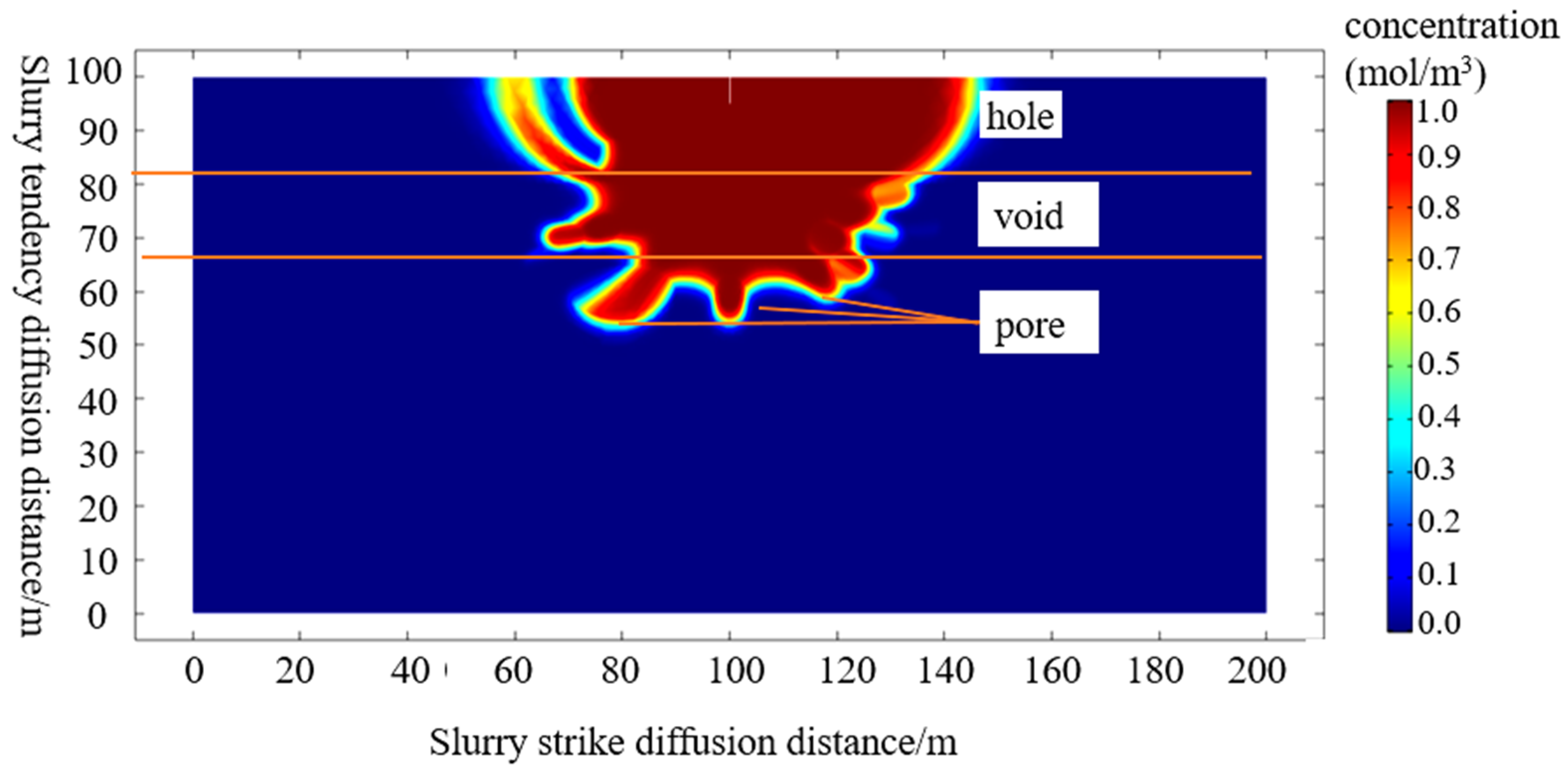
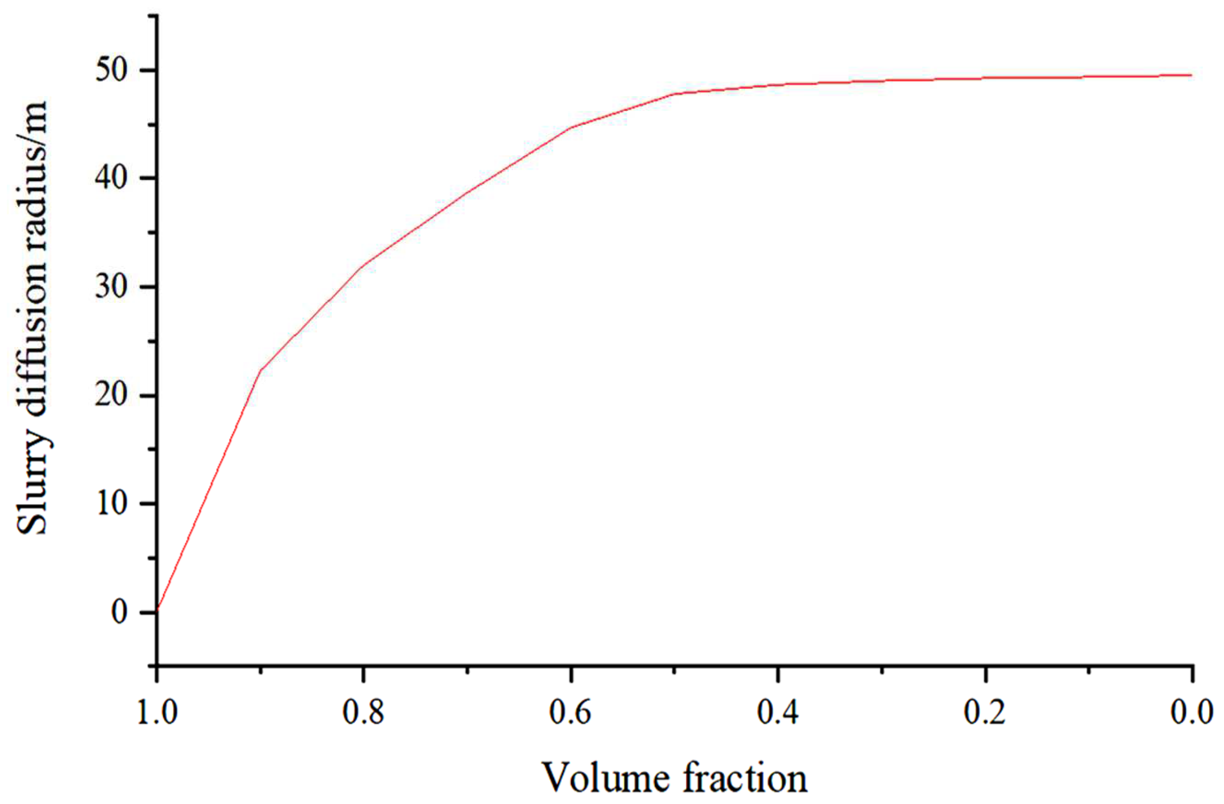
According to the shape and scope of the slurry diffusion, cavities will appear at the nozzle when the slurry extends along the inclination direction of the working face. The slurry also flows in the form of slop. The diffusion radius becomes smaller until the middle of the caving zone, the gangue tends to be compacted in the caving zone, and the slurry gradually penetrates the pores; that is, the slurry tends to diffuse along the working face with the “cavity–void–pore” multi-type residual space slowly. At the same time, the diffusion resistance and slurry morphology changed considerably. The diffusion radius of the slurry is about 50 m. The diffusion cloud map of the slurry in the direction of tendency and the attenuation curve of the volume fraction of the slurry with the diffusion radius are shown in Figure 7 and Figure 8.

3.2. Slurry Strike Diffusion Law

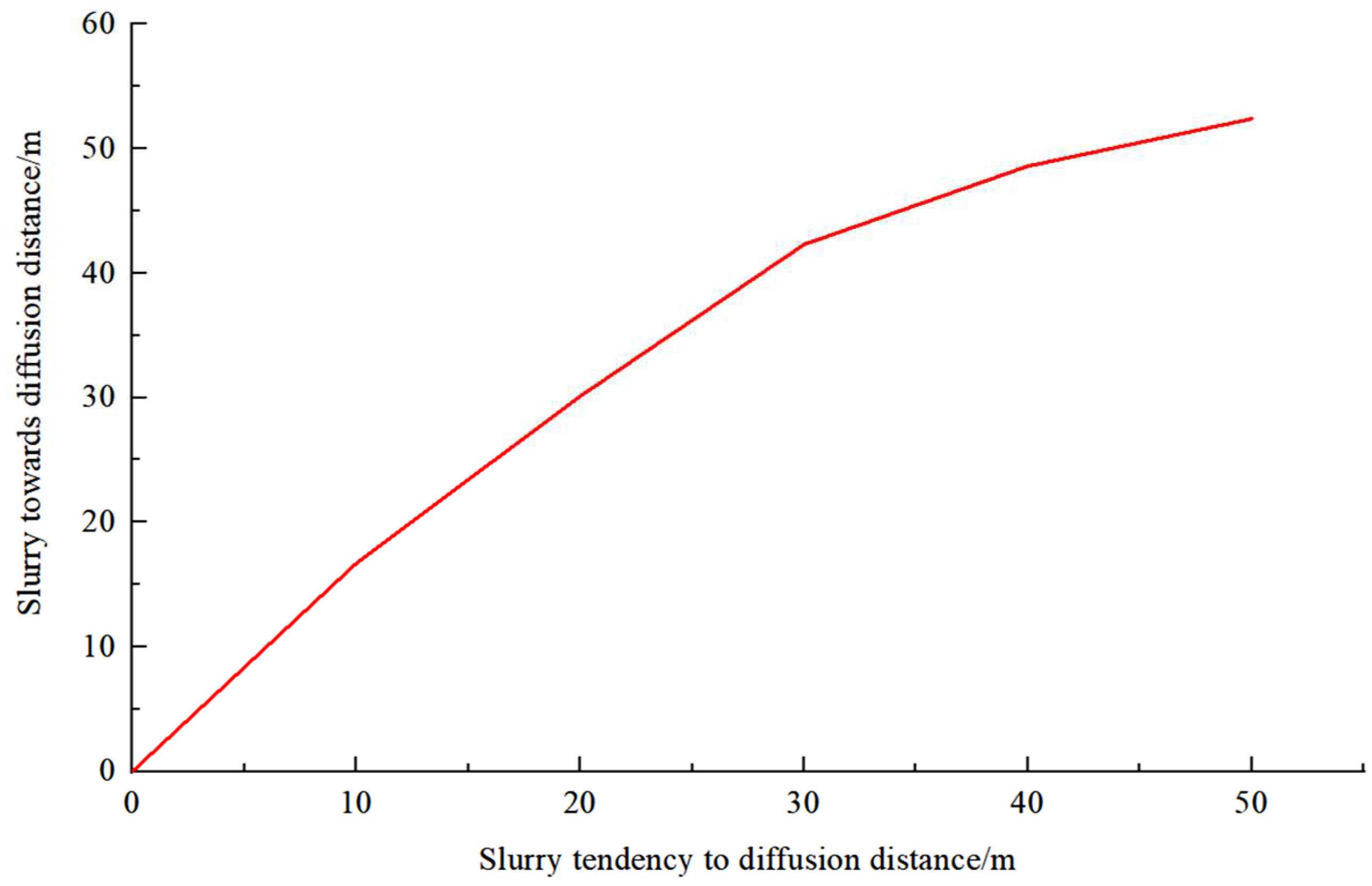
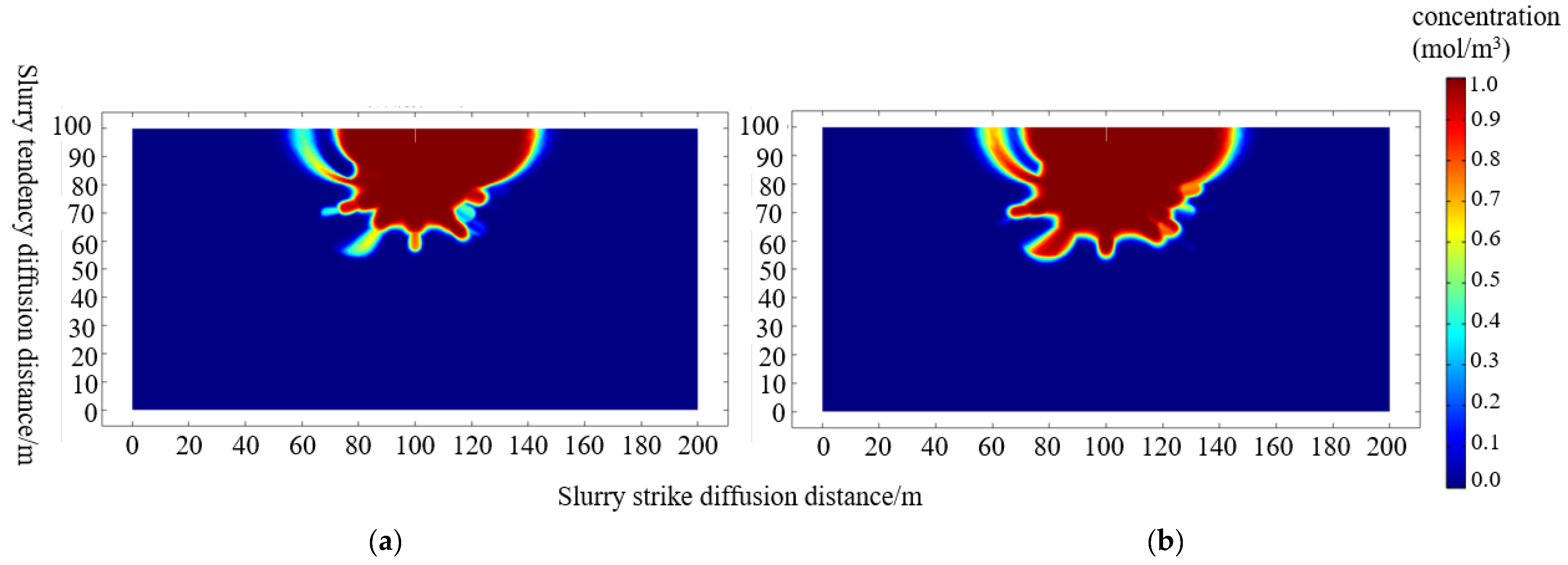
When the slurry spreads along the working face direction, the longitudinal direction of the caving zone is supported by the coal wall, the caving goaf is primarily hollow, the slurry diffuses in the form of flowing in the longitudinal direction, and the diffusion is the most obvious. The diffusion radius is about 52 m; comparing the diffusion patterns of the slurry at 30 min and 60 min, we found that the longitudinal diffusion distance of the slurry in the matrix pore medium increases with the increase in the grouting time. The increase rate is shown in Figure 9. At the same time, because of the coal wall, in the process of slurry diffusion, the slurry diffusion along the trend is slower than the trend diffusion, and the change curve of the slurry trend diffusion distance with the slurry trend diffusion distance is shown in Figure 10.

3.3. Influencing Factors of Slurry Diffusion Radius

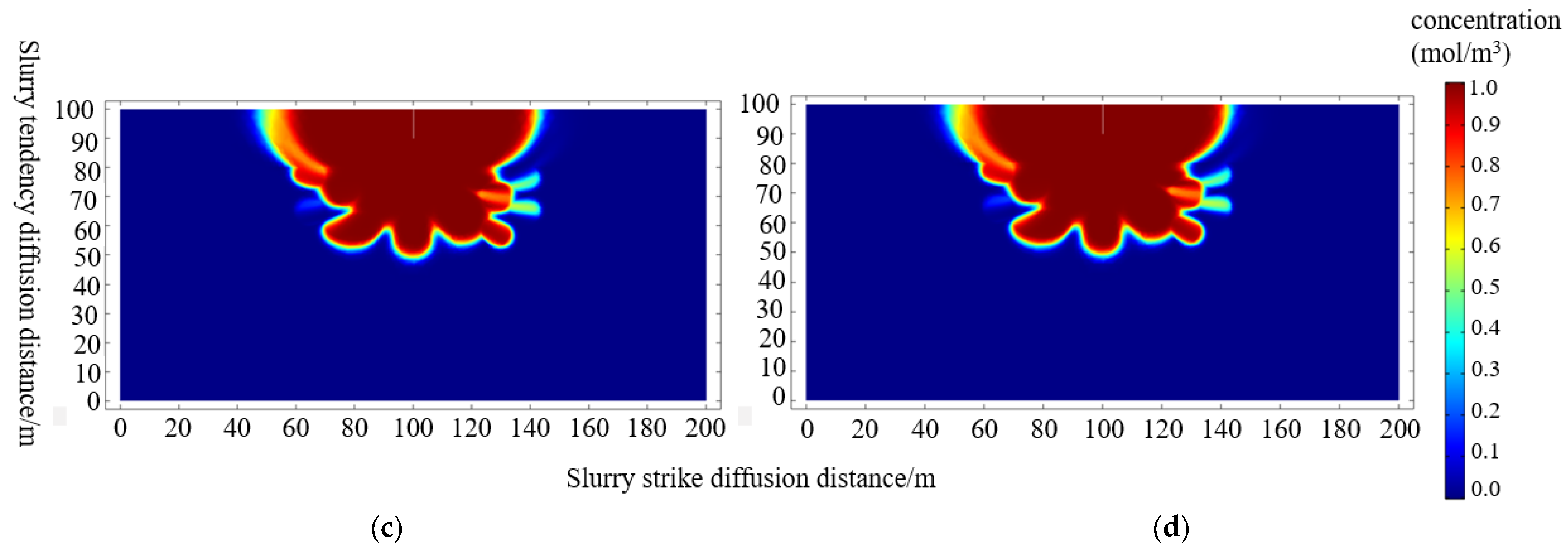
Under constant filling concentration, the diffusion range of slurry under the state and gradient change of inlet pressure was studied. However, when the limit value is reached, the slurry diffusion radius does not change significantly with the pump pressure. When the filling orifice pressure is 2 MPa, the maximum diffusion radius of a single hole is 51.58 m. The cloud map of the slurry diffusion radius under the isobaric gradient is shown in Figure 11.
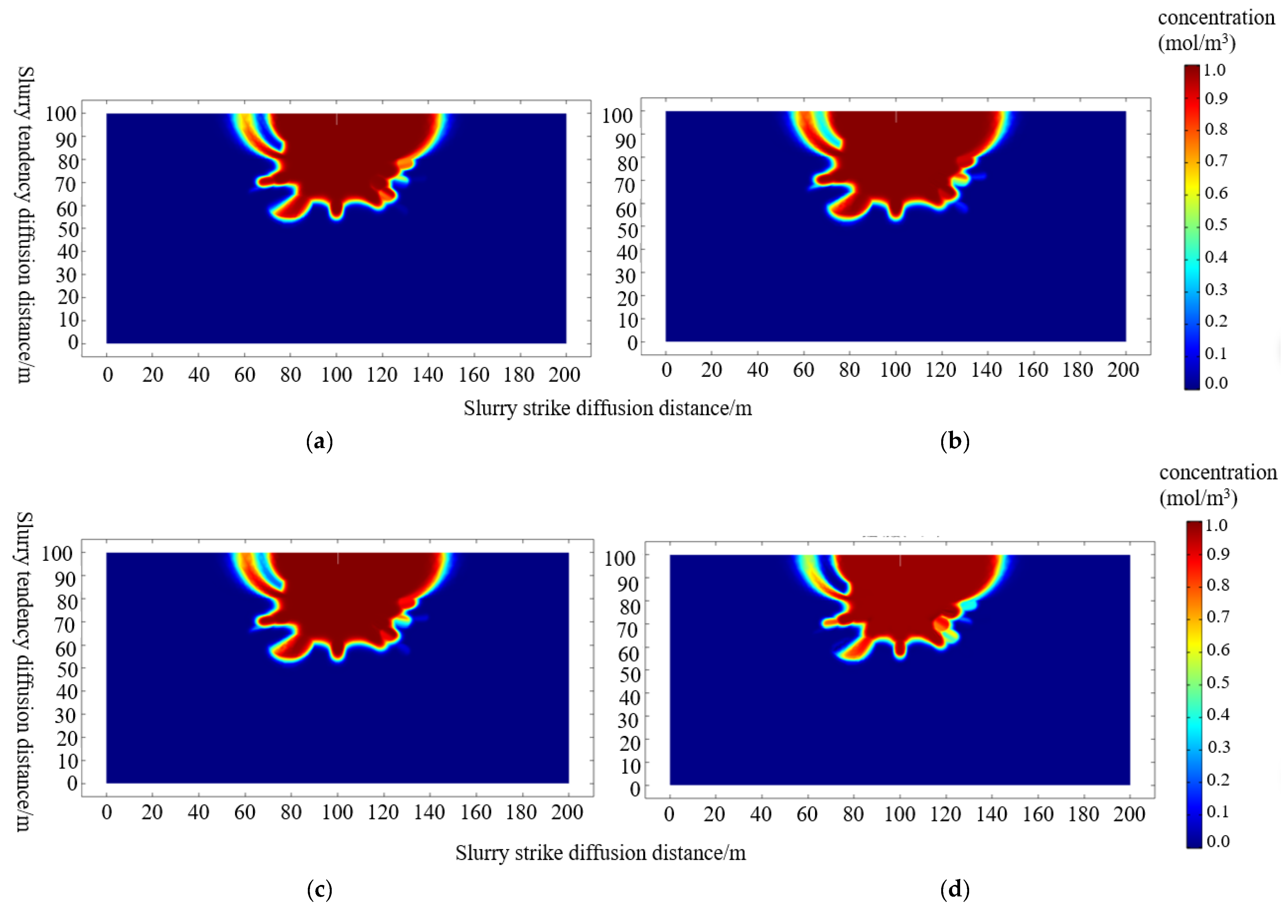
Under the constant pressure of 2 MPa, the diffusion range of slurry density under the gradient concentration state was studied. The study found that the larger the slurry concentration under continuous pressure, the smaller the diffusion radius. However, the effect of attention is small, and the radius is maintained at about 47~52 m. Figure 12 shows the cloud diagram of the impact of concentration on slurry diffusion.

3.4. Diffusion Rule of High and Low Pore Filling Slurry

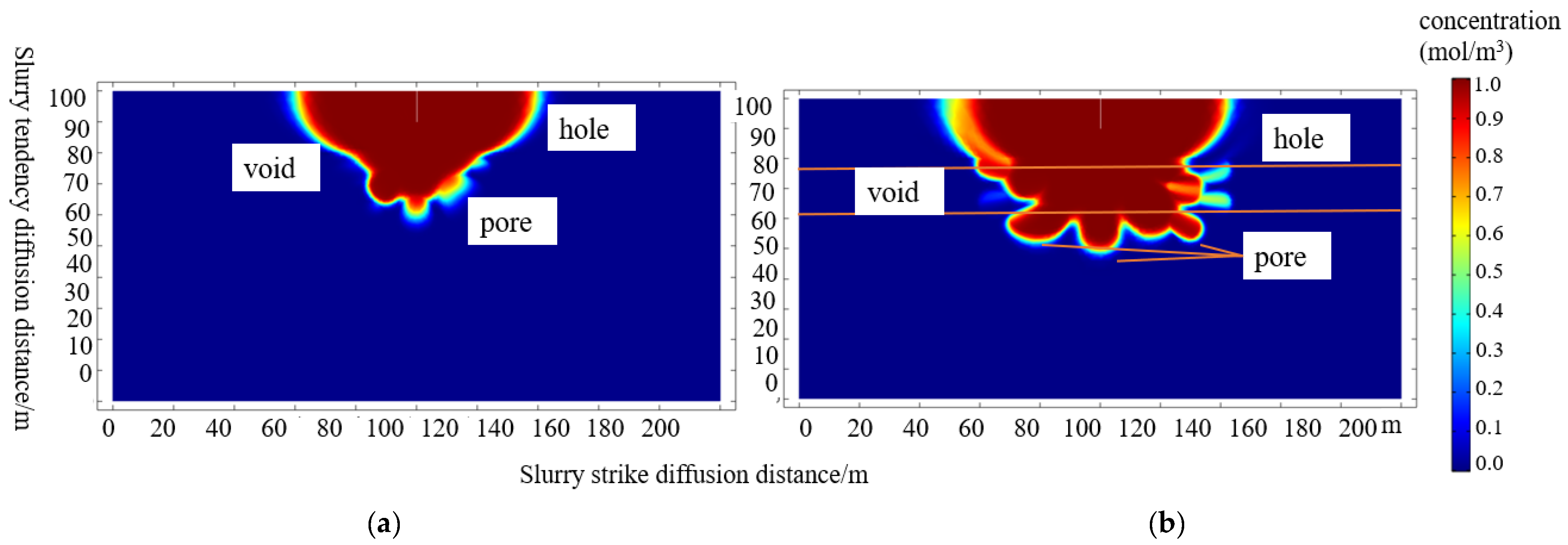
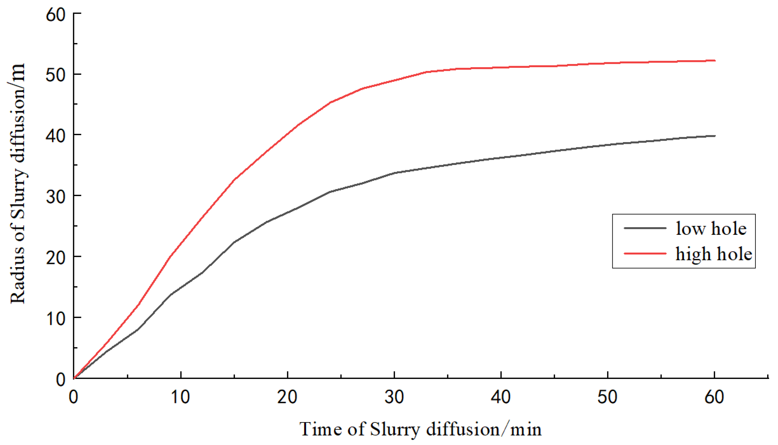
When the high-position hole is filled with slurry, because the final spot is located at the top of the caving zone, after the slurry enters the filling hole, the pump pressure and gravity will help the slurry to spread in the inclination direction. The volume of the slurry that can be filled is also significantly better than that of the low-position hole; the diffusion radius of the filling slurry of the high-position hole is about 51 m. When the low-position hole is filled with slurry, the slurry mainly flows in the cavities along the strike in the caving zone, and the diffusion pattern slows. The low-position hole grouting slurry has a diffusion radius of about 40 m. Figure 13 shows the diffusion cloud diagram of the grouting slurry in high- and low-position holes. Figure 14 shows the trend relationship between the filling slurry diffusion radius and the slurry diffusion time of the caving zone’s high and low filling holes.

4. Fluidization Filling Space in the Caving Goaf

4.1. Overview of Working Face

Taking the 3305 working face in the third mining area of Sangshuping well 2 as an example, the residual space in the caving goaf is calculated. The working face is a result of the comprehensive mechanized top coal caving mining process, with a coal thickness of 6 m and an overall inclination of 1°. The working face is arranged along the coal seam. The designed length of the two lanes is 920 m, the cutting width is 165 m, the recoverable length is 870 m, and the recoverable area is 143,550 m2. The coal seam floor elevation of the working face is +218~244 m, with an elevation difference of 26 m. There are 50 m coal pillars left in the east stoping line and the central auxiliary transportation main roadway, and there are 10 m coal pillars left in the south air inlet roadway and the return air of the 3304 fully mechanized top coal caving face; the north is adjacent to the design 3306 fully mechanized top coal caving face. The overview of the top and bottom plates is shown in Table 1 below.

4.2. Theoretical Prediction of Residual Space

According to [39], the 3307 working face is subcritical mining. It can be simplified as the superposition of two critical minings when subcritically mined. Then the simplified calculation formula of the residual voids and voids in the goaf is as follows:
h k = M M q M n cos α s x x D / 2 h k = M M q M n cos α s D x x D / 2
n = n 1 n 3                 n 1 / n 3 = k D H 0
In the formula, M is the mining thickness, m; q is the subsidence coefficient; n is the coefficient of mining influence; α is the coal seam angle, °; s is the distribution range of voids, s = H0/tanφ, where H0 is the average mining depth and φ is the angle of complete subsidence. D is the working face inclination and strike length D1 and D3; k is a coefficient related to the lithology of the overlying rock, taking the values 0.9, 0.8, and 0.7 for the soft, medium-hard, and hard rock layers, respectively.
According to the geological data, the mining thickness M is 6 m; the subsidence coefficient q is 0.85; the coal seam angle α is 0°; tanφ is the tangent of the main influence angle, which is 2.2; D is the working face inclination and strike length D1 and D3, 155 m and 868 m, respectively; k is 0.7. D1, D3, k, and H0 are substituted into Equation (2) to obtain n1 = 0.34, n3 = 1.90, and n = 0.80; M, q, n, α, and s are substituted into Equation (2) to obtain the following:
h k = 6 0.013 x x D / 2 h k = 6 0.013 D x x D / 2
When x = D/2, the residual void in the goaf and the void height hk = 0.358 m are calculated. Then the residual holes and invalid volumes in the goaf are obtained.
Considering that the fillable space utilization rate of the remaining voids and void volumes in the goaf is about 0.4, the actual fillable space is VL = 171,000 m3. The calculated residual space coefficient is 19.8%.

4.3. Calculation of Residual Space in Caving Zone by Fractal Dimension Theory

The voids inside the caving zone are usually irregular and disordered. According to the relationship between fractal dimension and porosity of caving rock blocks [40], the relationship between porosity and fractal dimension D is obtained as follows:
P = V M / ρ V = 1 ρ r max 3 - D ρ 0 r max 3 - D - r min 3 - D
ρ = H - h H ρ 0
r max = b H L 3
where P is the porosity, %; ρ0 is the density of the caving rock block, kg/m3; rmin is the diameter of the most severely broken, most numerous, and most minor rock blocks in the caving heap, m; ρ is the loose bulk density in the caving goaf, kg/m3; D is the fractal dimension; H is the height of the caving zone, m; h is the mining coal seam height, m; b is coal seam inclined length, m; L is coal seam strike length, m.
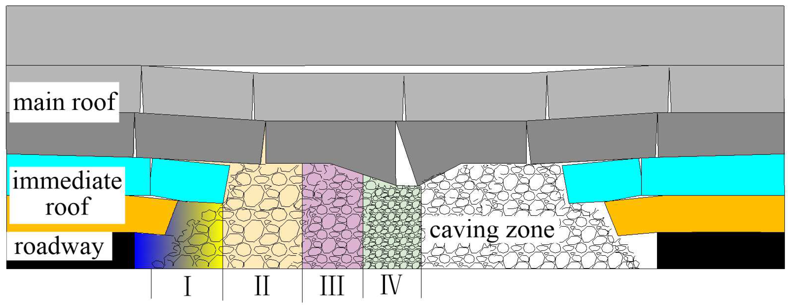
According to the stratum conditions of the test working face and the sampling observation of the gangue in the caving goaf, the false roof and the direct roof of the working face are easy to collapse, and the mudstone, sandy mudstone, fine sandstone, and medium sandstone in the gangue in the caving goaf are seriously broken, as shown in Figure 15. According to the step-by-step distribution law of “cavity void pore” in the residual space in the caving goaf of the working face, the goaf is divided into zones I, II, III, and IV according to the caving amount of the roof rock layer and the density of gangue. According to the Menger sponge fractal model, the statistical fractal dimension D of gangue in the caving goaf is calculated to be 2.765, and the corresponding porosity in areas I, II, III, and IV can be calculated from Equation (2): 32.6%, 20.27%, 12.33%, and 8.60%, respectively.
It can be known from the fissures in the caving goaf and the height of the stagnant space in the caving goaf [41] that after caving in the caving zone, the pore volume is mainly distributed in the caving zone and fracture zone, and the residual space height hv is obtained by integrating the porosity in the vertical direction from the caving zone floor to the top of the fracture zone, as shown in the following formula:
p z = e e Z H h v e 1 e 2 Z H ρ 0
h v ʹ = 0 H p z d z
The above equations are combined to obtain the following:
h v ʹ = p H e 1 2 e
The residual space in the caving goaf is obtained as follows:
V = S h v ʹ
The formula includes the working face area, m2; the residual height, m; and V, which is the residual space volume of the caving site, m3. Substituting the calculated porosity of the caving zone into Equation (6), it can be obtained that the retention heights at different positions in the caving zone are 2.47 m, 1.54 m, 0.94 m, and 0.65 m, respectively.
According to theoretical calculation, the volume of residual space in the caving goaf of the whole test working face is about 20,0970 m3, the residual space coefficient is 23.3%, and the filling volume of the slurry within 1 m on one side of the goaf strike direction is represented by the linear meter filling volume, so the filling volume of the single side of the working face is 97.1 m3.

4.4. Filling Borehole Design

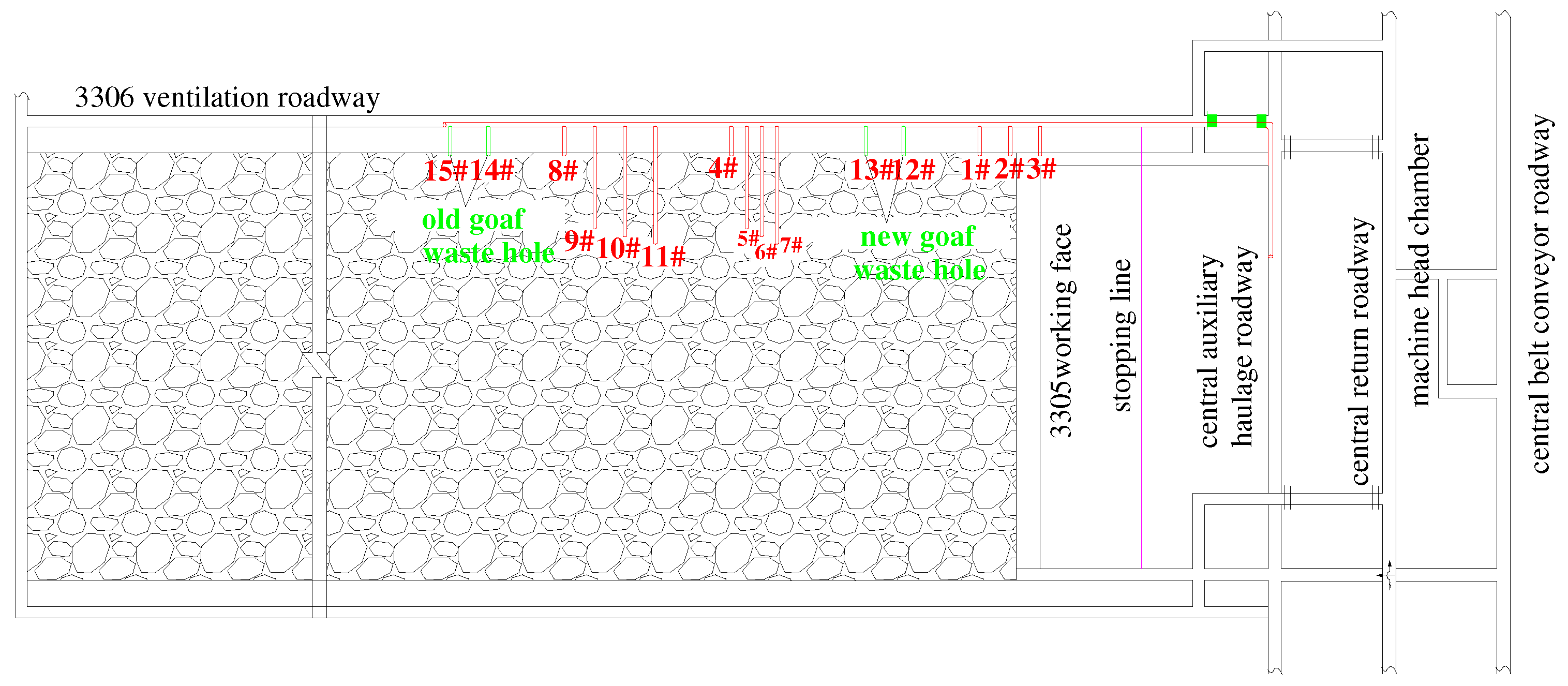
The backfill drilling design is mainly based on the research results of the “two belts” development law in the mine. The position of the final hole of the high-level hole is determined at the upper limit of the caving zone, the low-level horizontal hole is designed to pass through the coal pillar, and the end hole is located at the top of the coal seam. To thoroughly investigate the slurry diffusion law and ensure the effectiveness of filling holes, the three low-level horizontal filling holes are #1, #2, and #3, and the spacing is 12 m; the high-level hole group is #5, #6, and #7, with a spacing of 6 m and elevation angles of 31°, 45°, and 40°. The actual construction hole depths are 18 m, 20 m, and 40 m, respectively, and the final hole heights are 15.3 m, 20.1 m, and 31.7 m for holes #1, #2, and #3, respectively, and 5.1 m, 2.6 m, and 19.1 m for holes #5, #6, and #7, respectively. The #12, #13, and #4 horizontal holes are used as emergency waste holes, and the others are spare holes. The overall arrangement of the drilling holes is shown in Figure 16.
The depth of the on-site hole sealing shall not be less than 10 m. During the construction, steel pipes shall be used to protect the holes. After the holes are sealed, the casing shall be drilled to the design level. Each hole shall be equipped with valves and flanges [42,43,44].

5. Test Verification

5.1. Test Plan

In this test, the caving goaf of the test face was filled with grouting by filling the drilling holes in the adjacent roadway across the coal pillar. To simplify the test process, the gangue slurry used in the test was prepared in the commercial mixing station and then transported to the ground pump station by a tanker. The test used a KOS25100HP industrial filling pump, the maximum pumping pressure was 14 MPa, the entire delivery volume was 150 m3/h, the main filling pipeline was DN245 × 22Q345B (16 MN), the total length was 1840 m, and the real elevation difference was about 175 m. The process flow of the field-filling test is shown in Figure 17.
Two kinds of slurry, H-2 and S-1, were selected on-site to fill the caving goaf, the gangue aggregate used was for mine gangue discharge, and the crushed particle size was less than 5 mm. To avoid pipe blockage, a certain amount of additives were added to the test, and mortar was configured to lubricate the pipes before and after filling. The slurry ratio parameters are shown in Table 2. The depth of the on-site hole sealing was not less than 10 m. During the construction, steel pipes were used to protect the holes. After the holes were sealed, the casing was drilled to the design level. Each hole was equipped with valves and flanges.

5.2. Test Result

The field test lasted 15 days, with a total of 4949 m3 slurry filled and about 6414 t of gangue treated. The high-level holes were filled with 2421 m3, and the low-level horizontal holes were filled with a total volume of 2545 m3 slurry, of which the maximum amount of gangue slurry filled in the #5 hole reached 2183 m3. The filling test data are shown in Table 3.
(1)
Low-Level Horizontal Hole Filling Test
According to the filling test data, there is no pressure feedback at the orifice during the filling process of the #2 hole, and the filling is completed at 1103 m3. A small amount of slurry overflows in the retraction channel. At this time, the diffusion distance is 42 m. After the high-level hole filling test, the #13 and #12 holes were filled, the pump was stopped when the orifice pressure increased to 3.5~5 MPa, and a total of 1157 m3 of slurry was filled. Except for the #1 test hole, the average flow rate during the filling test of the low-level horizontal hole was 120~130 m3/h.
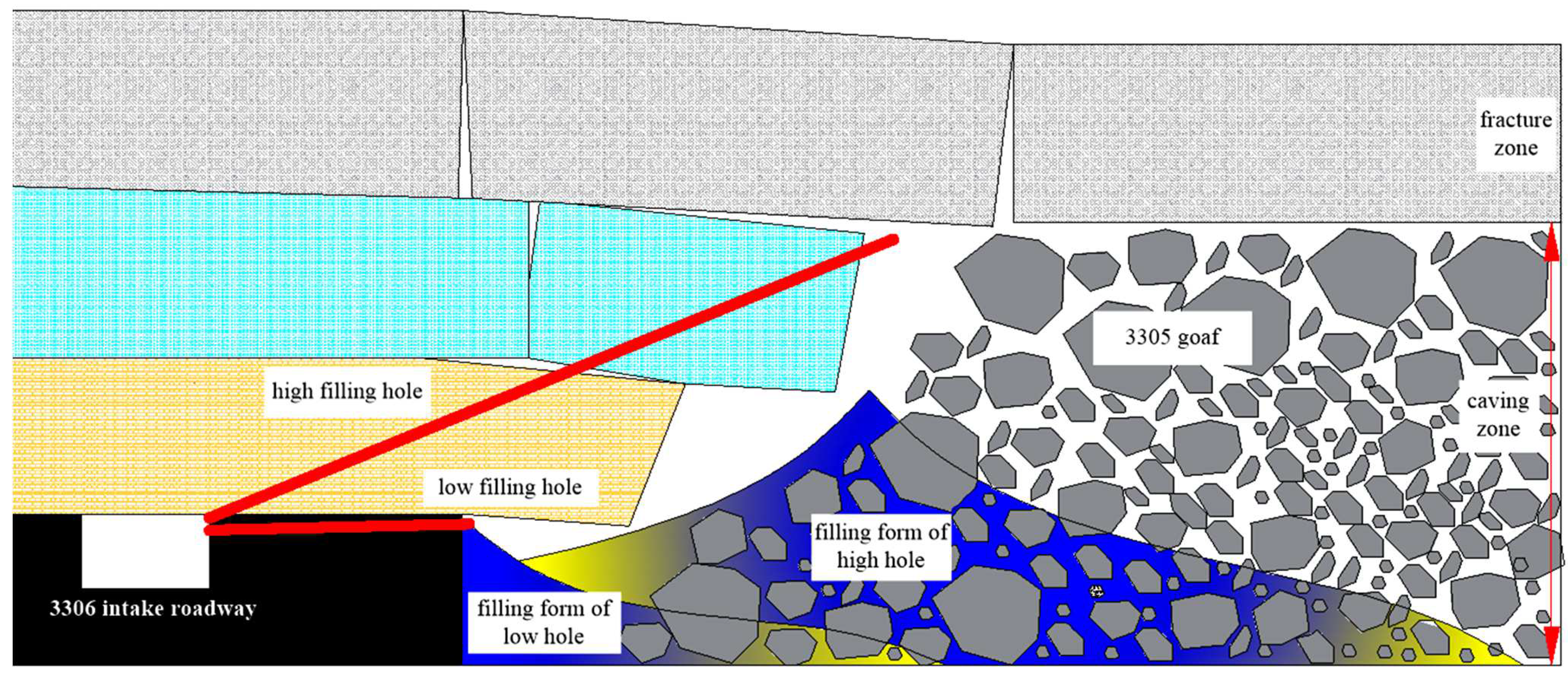
The characteristics of low-level horizontal hole slurry filling are as follows: ➀ The no-pressure stage lasts for a long time. It is mainly dominated by no-pressure flow diffusion in the strike direction. Due to the zoning characteristics of the roof caving shape and rock mass porosity in the caving goaf, there is a “channel effect” in the slurry diffusion. That is, when filling, the slurry is more likely to diffuse in the direction of small diffusion resistance, which is the “cavity” area connected along the path of the coal pillar, resulting in insufficient power for the slurry to diffuse to the depths along the inclination, as shown in Figure 18, ➁ According to the test results of H-2 and S-1 slurry, the proportion of slurry gangue parameters in the pressureless filling stage has little effect on the diffusion distance. At the same time, the significant influencing factor is the filling flow. During the pressing step, full play is given to the fluidity of the slurry so that it can quickly fill the “void” area in the direction of the trend and rapidly accumulate in the vertical order. ➂ Because the non-pressure filling slurry is expanded in the form of a cone when a single hole is used for filling, the slurry directly below the orifice accumulates faster. The thickness is more significant, but the slurry on both sides is thinner. Going to the “void” area, a porous arrangement should be adopted to make the slurry fill the weak spots on both sides of the orifice as soon as possible. ➃ The low-level horizontal holes are filled with 2545 m3 of slurry and 132 m3 of mortar. The rice filling volume is 31.9 m3.
(2)
High-Position Hole Filling Test
The #5 head hole was filled with 2183 m3 accumulatively, during which the pressure at the orifice did not increase sharply, and the actual diffusion distance of the slurry was about 47 m. The diffusion radius is basically the same as that of the COMSOL simulation slurry. Because the #7 hole was filled with high-parameter gangue slurry, the pump was stopped when the orifice pressure increased to 7 MPa.
In contrast, the characteristics of high-level hole filling are as follows: ➀ According to the test data of the #5 and #7 hole filling, it is believed that high-level hole filling is more suitable for slurry filling with medium flow and good fluidity, and slurry diffusion also has a “channel effect”. ➁ Due to the increased vertical height of the high-level hole, the diffusion time in the vertical and horizontal directions is longer, and the scope is more comprehensive. ➂ Due to the gravity effect of the high-level hole slurry, the slurry cannot easily accumulate in and block the cracks of the rock mass after the pump is stopped halfway, facilitating on-site construction management. ➃ According to the field test, the cumulative grouting volume of high-level holes is 2404 m3, and the mortar is 132 m3. According to the actual diffusion range of 94 m, the filling volume of high-level spots is 27.0 m3.
To further reduce the influence of the “channel effect” and ensure the filling effect, the following principles are followed: First, the high-position filling holes are preferred to increase the utilization rate of the residual space in the direction of the caving zone. Second, when high-level and low-level holes are co-filled, a small number of low-level horizontal holes should be used to fill the “cavities” along the strike in the caving goaf, and the “channel effect” should be reduced or eliminated through high-level filling holes. “Void–pore” and other residual spaces are efficiently filled.
(3)
Test Conclusion
In summary, it can be concluded that gangue slurry can be filled safely and efficiently through high- and low-level filling holes. According to the slurry diffusion law of high- and low-level hole filling, considering that the high- and low-level hole collaborative filling method is often used in the engineering scale, it can be preliminarily concluded that the linear meter filling volume on one side of the caving goaf of the test working face is 31.9~58.9 m3. Since the test filling amount is far less than the residual space in the caving goaf of the test working face, the test area is equivalent to no boundary constraint. During the filling test, the slurry only diffuses in the horizontal direction. In addition, in theory, the slurry diffusion range is controlled by pressure, but the actual filling port pressure is low, and there is no obvious pressurization stage. The slurry diffusion in the vertical direction does not play the role of slurry lifting. The residual space in the caving goaf of this test is not fully utilized. Therefore, the actual linear meter filling amount is less than the theoretical calculation amount.
Considering the actual situation of gangue fluidization filling in the caving goaf, when giving full play to the advantages of pumping equipment and ensuring the effect of gangue slurry filling under pressure, the influence of coal seam angle on slurry distribution can be ignored; that is, the difference of diffusion radius in strike direction and tilt direction is not considered.

6. Conclusions

(1)
Based on the results of transient electromagnetic exploration, there were four empty abnormal areas (containing water) and five empty abnormal areas (containing no water) in the study area. The actual residual space area of the detected caving goaf accounted for 23.5% of the whole study area. The detection results provided guidance for the accurate use of the residual space in the caving goaf.
(2)
The COMSOL simulation software was used to simulate and analyze the diffusion law of gangue slurry in the caving goaf. It is concluded that the gangue slurry spreads most obviously in the direction of the caving zone during the filling process, and diffusion in the inclination direction extends step by step in the multi-type residual space of “cavity–void–pore”. It is manifested that with the increase in diffusion distance, the diffusion resistance and slurry shape change significantly.
(3)
The industrial filling test was carried out. The test verified that the high and low filling holes in the caving goaf can safely and efficiently fill the gangue slurry. The technological characteristics of filling high- and low-level filling holes were summarized. Comprehensive numerical simulation and industrial tests were conducted. It is considered that there is a significant “channel effect” in the progressive extension of the multi-type residual space of “cavity–void–pore” in the gangue slurry, and reducing or removing the “channel effect” is an effective way to make efficient use of the residual space in the caving goaf.
This study has practical guiding significance for the application of gangue fluidization filling technology in thick seam caving goaves and enriches the research results of gangue fluidization filling technology.

Author Contributions

Conceptualization, Q.H. and L.L.; Experimental Design, Q.H., X.Z., J.W., J.Z.; Validation, L.L. and Y.H.; Data Curation, Y.H., B.W. and W.Z.; Supervision, Q.H. and L.L.; Writing—Original Draft Preparation, Q.H. and J.W.; Writing—Review and Editing, L.L., X.Z. and Y.H.; Project Administration, L.L. All authors have read and agreed to the published version of the manuscript.

Funding

This research was funded by the National Natural Science Foundation of China, grant No. 52074211, and the Natural Science Basic Research Program of Shaanxi, program No. 2019JLP-08.

Data Availability Statement

Not applicable.

Acknowledgments

We thank the National Natural Science Foundation of China and the Natural Science Basic Research Program of Shaanxi for their support of this study.

Conflicts of Interest

The authors declare no conflict of interest.

References

  1. Zhou, N.; Yao, Y.N.; Song, W.J.; He, Z.W.; Meng, G.H.; Liu, Y. Present situation and prospect of coal gangue treatment technology. J. Min. Saf. Eng. 2020, 37, 136–146. [Google Scholar]
  2. Rybak, J.; Gorbatyuk, S.M.; Kongar-Syuryun, C.B.; Khairutdinov, A.M.; Tyulyaeva, Y.S.; Makarov, P.S. Utilization of Mineral Waste: A Method for Expanding the Mineral Resource Base of a Mining and Smelting Company. Metallurgist 2021, 64, 851–861. [Google Scholar] [CrossRef]
  3. Zhang, Y.; Ling, T.C. Reactivity activation of waste coal gangue and its impact on the properties of cement-based materials e a review. Constr. Build. Mater. 2020, 234, 117424. [Google Scholar] [CrossRef]
  4. Tcvetkov, P.; Cherepovitsyn, A.; Fedoseev, S. Public perception of carbon capture and storage: A state-of-the-art overview. Heliyon 2019, 5, e02845. [Google Scholar] [CrossRef] [PubMed] [Green Version]
  5. Qin, L.; Gao, X.; Su, A.; Li, Q. Effect of carbonation curing on sulfate resistance of cement-coal gangue paste. J. Clean. Prod. 2021, 278, 123897. [Google Scholar] [CrossRef]
  6. Chen, W.; Liu, Y.; Wang, H.; Hnizdo, E.; Sun, Y.; Su, L.; Zhang, X.; Weng, S.; Bochmann, F.; Hearl, F.J.; et al. Long-term exposure to silica dust and risk of total and cause-specific mortality in Chinese workers: A cohort study. PLoS Med. 2012, 9, e1001206. [Google Scholar] [CrossRef]
  7. Field, R.W.; Withers, B.L. Occupational and environmental causes of lung cancer. Clin. Chest Med. 2012, 33, 681–703. [Google Scholar] [CrossRef] [Green Version]
  8. Miao, X.X. Progress of fully mechanized mining with solid backfilling technology. J. China Coal Soc. 2012, 37, 1247–1255. [Google Scholar]
  9. Cavusoglu, I.; Yilmaz, E.; Yilmaz, A.O. Sodium silicate effect on setting properties, strength behavior and microstructure of cemented coal fly ash backfill. Powder Technol. 2021, 384, 17–28. [Google Scholar] [CrossRef]
  10. Holmquist, D.V.; Thomas, D.B. Subsidence mitigation using void fill grouting. Geol. Soc. Lond. Spec. Publ. 2003, 120, 1103–1114. [Google Scholar]
  11. Ma, H.W.; Sui, W.G.; Ni, J.M. Environmentally sustainable mining: A case study on surface subsidence control of grouting into overburden. Environ. Earth. Sci. 2019, 78, 320. [Google Scholar] [CrossRef]
  12. Cao, W.H.; Wang, X.F.; Li, P.; Zhang, D.S.; Sun, C.D.; Qin, D.D. Wide Strip Backfill Mining for Surface Subsidence Control and Its Application in Critical Mining Conditions of a Coal Mine. Sustainability 2018, 10, 700. [Google Scholar] [CrossRef] [Green Version]
  13. Zorychta, A.; Chojnacki, J.; Krzyzowski, A.; Chlebowski, D. Potentials of mining in remnants in polish coal mines. Gospod. Surowcami Miner. (Miner. Resour. Manag.) 2008, 24, 169–184. [Google Scholar]
  14. Fall, M.; Celestin, J.; Sen, H.F. Potential use of densified polymerpastefill mixture as waste containment barrier materials. J. Waste Manag. 2010, 30, 2570–2578. [Google Scholar] [CrossRef] [PubMed]
  15. Wang, X.M.; Zhao, B.; Zhang, C.S.; Zhang, Q.L. Paste-like self-flowing transportation backfilling technology based on coal gangue. Int. J. Min. Sci. Technol. 2009, 19, 137–143. [Google Scholar] [CrossRef]
  16. Rybak, J.; Khayrutdinov, M.M.; Kuziev, D.A.; Kongar-Syuryun, C.B.; Babyr, N.V. Prediction of the geomechanical state of the rock mass when mining salt deposits with stowing. J. Min. Inst. 2022, 253, 61–70. [Google Scholar] [CrossRef]
  17. Yu, G.G.; Mi, W.R.; Wang, D.N.; Gao, L.Y.; Lu, S.B.; Li, G. Research on the Relationship between the Surface Dynamic Subsidence and Overburden Separated Strata of Coal Mine and Its Model. Procedia Eng. 2017, 191, 196–205. [Google Scholar] [CrossRef]
  18. Andre, Z.; Anderson, W. Subsidence over room and pillar retreat mining in a low coal seamInternational. J. Min. Sci. Technol. 2019, 29, 51–57. [Google Scholar]
  19. Ren, W.S.; Qiu, W.Z. Analysis of Separation and Dislocation Characteristics of Layered Roof in the Mined-Out Areas. Appl. Mech. Mater. 2012, 256–259, 75–78. [Google Scholar]
  20. Zhu, L.; Gu, W.Z.; Pan, H.; Liu, Z.C.; Chai, J.; Ouyang, Y.B. Calculation model of overburden rock failure volume in mined-out area based on Brillouin optical time-domain analysis technology. Opt. Fiber Technol. 2021, 66, 102640. [Google Scholar] [CrossRef]
  21. Qian, M.G.; Xu, J.L. Study on “O” ring characteristics of mining induced fracture distribution in overburden. J. China Coal Soc. 1998, 5, 20–23. [Google Scholar]
  22. Guo, G.L.; Miao, X.X.; Zhang, Z.N. Research on Ruptured Rock Mass Deformation Characteristics of Longwall Goafs. J. Eng. Sci. Technol. 2002, 5, 44–47. [Google Scholar]
  23. Zhu, L.; Pan, H.; Gu, W.Z.; Zhao, M.Y.; Zhang, X.F.; Xu, K. Experimental study on flow and diffusion law of gangue filling slurry in caving zone. J. China Coal Soc. 2021, 46, 629–638. [Google Scholar]
  24. Chang, G.F.; Hua, X.Z.; Liu, X.; Li, C.; Wang, E.Q.; Sun, B.G. Fluidity Influencing Factor Analysis and Ratio Optimization of New Filling Slurry Based on the Response Surface Method. J. Renew. Mater. 2022, 10, 1439–1458. [Google Scholar] [CrossRef]
  25. Liu, Q. Regularity Research of Goaf Grouting Diffusion of Yang-Yi Freeway; Xi’an University Of Science And Technology: Xi’an, China, 2013. [Google Scholar]
  26. Wu, D.; Zhang, Y.L.; Wang, C. Modeling the thermal response of hydrating cemented gangue backfill with admixture of fly ash. Thermochim. Acta 2016, 623, 86–94. [Google Scholar] [CrossRef]
  27. Sun, W.B.; Wang, Y.; Qiu, H.F.; Ding, Z.W. Numerical simulation study of strip filling for water-preserved coal mining. Environ. Sci. Pollut. Res. 2020, 27, 12899–12907. [Google Scholar] [CrossRef]
  28. Michalczyk, Z.; Chmiel, S.; Glowacki, S.; Borowska-Pakula, J. Water resources threats in the leczna-wlodawa lake district as the result of mining activity. Monogr. Kom. Gospod. Wodnej Pol. Akad. Nauk 2018, 41, 161–171. [Google Scholar]
  29. Wang, L.H. Application Research of High Density Electric Method and Transient Electromagnetic Method on Colliery Gob; Chengdu University Of Technology: Chengdu, China, 2020. [Google Scholar]
  30. Liu, H. Research on Transient Electromagnetic Method Detection in Goaf of Hangshaotai Railway; China University Of Geosciences: Wuhan, China, 2019. [Google Scholar]
  31. Yang, Y. Study of Mechanism of Controlling. The Overlying Rock by Injecting Ash Thick Liquid into the Mining Collapse Zone; Liaoning Technical University: Fuxin, China, 2007. [Google Scholar]
  32. Chen, Z.M.; Luo, X.; Yin, Z.X.; Li, W. Electrical method exploration technology for goaf in Pingshuo mining area. J. Liaoning Tech. Univ. 2021, 40, 112–119. [Google Scholar]
  33. Wang, Y.; Su, B.; Xu, Z.Y. Review on seepage model of fractured rock mass. J. Adv. Water Sci. 1996, 3, 93–99. [Google Scholar]
  34. Biot, M.A. General of Propagation of elastic waves in a fluid-sat-urated porous solid Low-frequency range. Acoust. Soc. Am. 1956, 28, 168–178. [Google Scholar] [CrossRef]
  35. Long, J.; Remer, J.; Wilson, C. Porous media equivalents for networks of discontinuous fractures. Water Resour. Res. 1982, 18, 645–658. [Google Scholar] [CrossRef]
  36. Wang, Q.S. Study on the Numerical Simulation of the Goaf Grouting of the South-to-North Water Transfer Project; Tianjin University: Tianjin, China, 2014. [Google Scholar]
  37. Zheng, D.Z. Study on Grout Diffusion in Fracture-Pore Medium; Shandong University: Jinan, China, 2016. [Google Scholar]
  38. Wang, Q.; Feng, Z.Q.; Wang, L.X.; Tang, D.H.; Feng, C.; Li, S.H. Numerical analysis of grouting radius and grout quantity in fractured rock mass. J. China Coal Soc. 2016, 41, 2588–2595. [Google Scholar]
  39. Zhang, H.Z.; Deng, K.Z.; Gu, W. Study on the distribution law of residual voids in old goaf. J. Min. Saf. Eng. 2016, 33, 893–897. [Google Scholar]
  40. Li, X.S. Study on Mechanism of the Grouting Backfill in Caving Area with Strip Mining under Buildings; China University of Mining and Technology: Xuzhou, China, 2008. [Google Scholar]
  41. Wang, Y.T. Three-dimensional spatial dynamic distribution model on porosity and permeability characteristics of porous media in goaf. J. Saf. Sci. Tech. 2020, 16, 40–46. [Google Scholar]
  42. Gu, W.Z.; Zhu, L.; Liu, Z.C.; Song, T.Q.; Pan, H.; Zhang, X.F.; Qiu, F.Q.; Zhao, M.Y.; Huang, J.B. Fluidization slurry backfilling technology of coal mine solid waste. J. Coal Sci. Technol. 2021, 49, 83–91. [Google Scholar]
  43. Zhu, L.; Song, T.Q.; Gu, W.Z.; Xu, K.; Liu, Z.C.; Qiu, F.Q.; Yuan, C.F. Experimental research on transport resistance characteristics of gangue slurry and its flow trend in the goaf. J. China Coal Soc. 2022, 47, 39–48. [Google Scholar]
  44. Pei, L. Research on Slurry Diffusion Law of Horizontal Grouting Hole in Ordovician Karst Fissure Aquifer; General Coal Research Institute: Beijing, China, 2018. [Google Scholar]
Figure 1. Plan of surface survey lines and detection range in the caving goaf of the 3307 working face.
Energies 15 08164 g001
Figure 2. Section results of the transient electromagnetic apparent resistivity of survey line TMP-Z14.
Energies 15 08164 g002
Figure 3. Section results of the transient electromagnetic apparent resistivity of survey line TMP-Z19.
Energies 15 08164 g003
Figure 4. Results of apparent resistivity slice at 250 m depth of the caving goaf.
Energies 15 08164 g004
Figure 5. Geological interpretation floor plan at 250 m depth of the caving goaf.
Energies 15 08164 g005
Figure 6. Schematic diagram of pore media and fractures.
Energies 15 08164 g006
Figure 7. Diffusion cloud diagram of slurry tendency direction in caving goaf.
Energies 15 08164 g007
Figure 8. Attenuation curve of slurry volume fraction with diffusion radius.
Energies 15 08164 g008
Figure 9. Diffusion program of slurry strike direction in the caving goaf.
Energies 15 08164 g009
Figure 10. The increasing curve of slurry trend diffusion distance with slurry tendency diffusion distance in the caving goaf within 60 min.
Energies 15 08164 g010
Figure 11. Slurry diffusion program of goaf: (a) pressure 0.5 MPa, radius 42.38 m; (b) pressure 1 MPa, radius 46.63 m; (c) pressure 2 MPa, radius 51.58 m; (d) pressure 3 MPa, radius 52.02 m.
Energies 15 08164 g011aEnergies 15 08164 g011b
Figure 12. Concentration affects the slurry diffusion program: (a) concentration 73%, radius 49.45 m; (b) concentration 75%, radius 51.34 m; (c) concentration 78%, radius 50.89 m; (d) concentration 80%, radius 47.23 m.
Energies 15 08164 g012
Figure 13. Nephogram of filling slurry diffusion in low and high filling holes in goaf: (a) grouting slurry in a low position; (b) grouting slurry in the high position.
Energies 15 08164 g013
Figure 14. Trend curve of slurry diffusion radius and slurry diffusion time in high and low filling holes in caving zone.
Energies 15 08164 g014
Figure 15. Schematic diagram of strike profile of residual space in caving goaf.
Energies 15 08164 g015
Figure 16. Design plane drawing of backfill drilling in test working face.
Energies 15 08164 g016
Figure 17. Process flow of field-filling test.
Energies 15 08164 g017
Figure 18. Profile of slurry diffusion and filling direction of high-level hole and low-level hole.
Energies 15 08164 g018
Table 1. Overview of top and bottom plates of 3305 working face.
CategoryComponentThickness (m)Nature
False RoofMudstone–sandy mudstone0.05–0.5Soft, broken, joint development, easy to collapse
Direct RoofSandy mudstone–fine sandstone2.5–5.5Thick layered, horizontal bedding, plant stem and leaf fossils can be seen on the bedding surface, joints and fissures are developed
Old RoofMedium and fine-grained sandstone2.5–5.5Medium sorting, poor roundness, calcium and mud cementation, parallel bedding, oblique bedding
First RoofSiltstone or argillaceous siltstone1.3–2.5Medium–thick layered, clayey cemented, with plant fossils
Table 2. Slurry proportioning parameters.
GroupMass Fraction (%)Mass
Concentration
(%)
Slurry Density (kg·m−3)Characteristic
GangueOther
Materials
Water
H-255.520.524761850The slurry has high viscosity, good fluidity, and low amount of gangue
S-175223761820Poor fluidity and viscosity, moderate diffusivity, high amount of gangue
Y-17600761800Poor fluidity, weak diffusivity, and the highest amount of gangue
mortar0604060 Homogeneous slurry, used for lubricating and flushing before and after filling
Table 3. Statistics of filling test.
Filling
Sequence
Filling Hole
Number
FrequencyProportion
Number
Filling Slurry
Volume (m3)
Fill Mortar
Volume (m3)
Average Flow
(m3/h)
Orifice
Pressure (MPa)
Remark
#11H-228524600.2debugging
#21S-11103601200.2
#51S-11063491010.3
#71Y-1221481007plugging holes
#52H-21120241000.3
#131S-1540121103.5
#121S-1617361204plugging holes
Publisher’s Note: MDPI stays neutral with regard to jurisdictional claims in published maps and institutional affiliations.