Abstract
Adaptive façades represent a viable and effective technological solution to reduce the building energy demand for cooling while achieving interesting aesthetic effects on the building envelope to screen solar radiation. During the last decade, many different design solutions, including those based on shape memory alloys, have been experimented to obtain appropriate responses without being dependent on electro-mechanically actuated systems. Several recent and ongoing studies have been published in the scientific literature regarding the different actuator typologies, as well as the different properties of the materials used, which usually determine the adaptive solution characteristics after a series of complex and time-consuming simulations using specialised dynamic modelling software. Due to the time and resources required, this kind of evaluation is usually delivered during the last and more advanced design stage as a form of assessment of already-taken architectural and technological choices. The study reported in the paper aims to offer a quick, time-saving simplified algorithm to calculate the response of an adaptive façade, according to the ISO 13790 standards, to be adopted during the early design stage to evaluate the possible effects of design decisions. The study includes three main steps: (a) the conceptualisation of the adaptive solution considering the context conditions; (b) the definition of the calculation algorithm; (c) the application of the method to a test room in a case study building located in Bologna for supporting the discussion of the related outcomes.
1. Introduction, Context and Background
The increasing awareness regarding the need to effectively support the transition towards energy-efficient models in the building sector and the attention paid during the last decade to the shift towards nearly zero energy buildings (NZEB) [1] and positive energy buildings (PEB) gave a new impulse to the research on better performing building envelope solutions with the purpose of possibly optimising their response capacity to varying environmental conditions. This is potentially true for most of building systems and sub-systems, but it is particularly relevant with reference to building façades, where innovative and experimental solutions able to adapt to externally driven changes have been explored to replace or integrate the conventional “static” ones, and curtain walls particularly.
The main scope of “adaptive” façades basically deals with reducing summer overheating—which is largely increasing due to the impacts of climate change [2,3,4]—while maximising passive solar gains during winter [5]. Despite the importance of reducing energy demand during winter, which has always been a priority in most design strategies, the ever-increasing effects of global warming are rapidly moving the attention towards the energy demand for cooling during the hot summer period, which represents the most urgent scenario to cope with in many countries. This is usually achieved—even in conventional solutions—by adopting shielding systems to be placed over the glazed or opaque wall surfaces to reduce the amount of incident solar radiation. In both cases, it is particularly important to define the shading or screening percentage to calculate the reflected solar radiation during summer and the loss of solar gain (if any) during winter. This strictly depends on the shading system configuration and characteristics, which can be very different in the case of static or dynamic solutions [6]. The introduction of dynamic systems represents the designers’ attempt to provide a proper response to the variations in the involved environmental parameters, which usually occur on a daily or seasonal basis. It can be argued that a number of different manually operated options can be observed in the history of architecture and movable shading systems are not innovative themselves. The novelty lies in the ambition to automatically manage the process to adjust the shading system configuration according to the detected external environmental conditions. This was initially achieved by adopting electro-mechanical centralised systems operated according to input data registered by dedicated sensors.
According to Loonen et al. [7], the term “adaptive” is, therefore, to be regarded as the capacity to dynamically vary the façade’s configuration as a response to environmental changes according to the detection of specific parameter variations, to which climate-adaptive building shells [CABS] basically refers, with a specific focus on how to define intelligent skin façades by Wigginton and Harris [8] and Michael and Jude [9], performance assessments by Basurto et al. [10] and mechanism examples of CABS by Fattahi, Tabasi and Banihashemi [11].
The scientific literature provides several studies about many different adaptive envelopes, covering the broad domain of kinetic systems and linked to traditional materials [12,13] focusing on the control typologies, the relation between the dynamism and the effect on the architectural layout [14,15], the prototyping and self-shaping building skin [16,17], the functional features [9] and the perceptive issues [18].
Despite the progress made during the last decades, electro-mechanical systems still suffer from their dependence on a supplied energy source and from quite high maintenance costs, which reduce their diffusion at a larger scale. Alternative options were explored to possibly avoid the use of any electric sources, leading to the distinction [19,20] between:
- Active systems when dynamism is remotely controlled by a CPU-driven electrical stimulus;
- Passive systems when dynamism is directly induced by the capacity of the material itself.
In this second case, the device is strictly associated with the so-called “smart material” which operates as a sensor, processor and actuator at the same time [21]. Although a shared definition in this field is still lacking [22,23,24], passive systems typically react to environmental parameters such as temperature, humidity, light, etc., providing an instant or very rapid response to their variations. Smart materials include shape memory alloys [25], phase change materials [26], photovoltaic [27] and photochromic glass [28], thermo-bimetal, etc., and others inspired by biology [29,30] and phytobiology [31].
When the adaptive capacity is an intrinsic feature of the building envelope sub-system, it is usually classified as an intrinsic control system, self-adjusting according to temperature, humidity, light, etc., or whatever the driving stimuli [32,33,34]. This led many studies to focus on the specific response of materials: Aresta (2018) [35] and Yoon (2018) [36,37,38] on temperature-responsive materials; Li (2018) [39] on shape memory polymers [SMP]; Holstov et al. (2015) [40] on thermo-bimetals; Reichert et al. (2015) [41], Holstov et al. (2017) [42] and Abdelmohsen (2019) [43] on wood/natural fibre-based systems; and Vazquez et al. (2019) [44] on other possible combinations. Other studies (Persiani et al., 2016 [32]; Formentini and Lenci, 2018 [45]; Barozzi et al., 2016 [46]; Loonen, 2013; Ricci et al., 2020 [47,48]) focused more on the energy implications in terms of demand for operating and/or saving potential derived from the adoption of adaptive solutions. Because active systems largely depend on energy infrastructure, passive systems are preferable in the case that a very NZEB or PEB concept is targeted. Accordingly, the study reported in the present paper mainly focuses on the use of this second typology despite the fact that it can be reasonably expanded to include the first one.
The initial design assumption is, therefore, the use of a self-sufficient system, passively actuated to possibly optimise indoor thermal comfort according to daily environmental condition variations and without the end-users being asked to contribute to setting the system. However, as evidenced by Bakker et al. (2014) [49], a fully automated system can reduce the level of acceptance and satisfaction of the occupants, especially in relation to visual requirements.
Another significant limitation of passive solutions is generally that the system’s responsiveness is “set” during the fabrication process and cannot be changed during the time following (Khoo et al., 2011 [50]).
The effectiveness of any adaptive system, particularly of self-sufficient ones, strictly depends on the façade concept and the actuator typology. As evidenced by Persiani et al. (2016) [32] and Vazquez et al. (2019) [44], this can lead to very different classifications of system behaviour. However, according to Lopez et al. [51], four main categories can be identified: temperature-responsive, light-responsive, humidity-responsive, and CO2-responsive solutions. In most cases, the solution belongs to the first two categories, sometimes also considering seasonal variations according to Correa and Augustin [52].
Passive actuators operate as transducers exploiting the capacity of the sensitive material to convert a certain typology of energy into motion, generating the dynamic effect of the kinetic component. The conversion into kinetic energy is mainly due to thermal expansion, hygroscopicity and the shape memory effect.
Due to their conductivity properties, thermal expansion is mainly associated with metals (or bimetal) and also with other materials such as paraffin wax, by Molter et al. [53], XPS panels, by Barrett and Barrett [54] and hydrogel, by Khoo and Shin, 2018 [31,50].
Wood has been recently experimented among hygroscopic materials, for both its reduced costs and the potential to customise the bending pattern, by Abdelmohsen et al. [43,55] and Anis [56]. Shape memory materials—mainly shape memory alloys (SMAs), shape memory polymers (SMPs) or shape memory hybrids (SMHs)—have a dual solid phase actuated by the specific environmental trigger.
These materials have two main phases: in the first one, they are inert and easily deformed, while in the second, they recover the initial molecular structure and the related shape that can be set “at will” according to a predefined layout [13,21,57].
The adoption of passive actuators in shading systems of adaptive shells represents a viable and cost-effective solution to improve energy savings, reduce the remote control implications, formally characterise the architectural façade layout by Drozdowski [58], Moloney [59] and Elghazi [60], or integrate energy production devices by Dewidar [61] and early design stages by Negendhal and Nielsen [62]. However, the very basic scope is to reduce the incident solar radiation and the derived overheating during the summertime while allowing for maximum solar gains during wintertime, keeping the optimal natural light levels during both seasons. If evaluating the behaviour of the building by considering the impact of the adaptive façade adoption is possible using dynamic software (such as Trynsys, EnergyPlus or others), estimating the benefit derived by a single shielding element (or module) during the design stage is more difficult, particularly regarding actuation settings. The outcomes strictly depend on the relationship between the actuator and the system components, both in terms of language and in terms of technical complexity. The actuator can be a separate independent part of the entire kinetic component or embedded into its structure, although it is still a separate part, or be perfectly coincident with the kinetic component itself.
The scientific literature does not provide comparative studies about the use of building simulations as most of the papers are strictly focused on a specific issue (heat transfer, computational fluid dynamics (CFD), energy performance, etc.) adopting a different software. Abu-Zidan focuses on the computational implications of the CFD simulation of tall buildings [63], while Lv et al. focus on naturally ventilated livestock buildings [64], and Zheng et al. [65] on simulation at the urban scale. A common consequence is the need for a considerable amount of time for both the preparation of the model and the computation, which is an issue even in experimental contexts (and even more in the ordinary design market). As evidenced by Blazquez et al. [66], CPU computation time in building energy performance is largely dependent on the number of equations derived from the modelling approaches. As remarked by Magni et al. [67] and other studies [68,69], not only do the modelling approaches influence computation time but they are time-consuming themselves, shifting the attention to the so-called doftware usability of computing algorithm (SUCA). Particularly with reference to complex solutions—as adaptive façades could be—SUCA refers to:
- (a)
- The training time as the time needed to train the personnel to the software use (i.e., Energyplus [70], Trynsys, ESP-r, IES.VE, Designbuilder, ACAD Multiphysics, COMSOL, FLUENT);
- (b)
- The time to insert data (depending on the involved parameters) during the modelling phase [71];
- (c)
- The computation time, which is influenced by the software architecture and the calculation capacity of the workstation.
Training time may range from a couple of weeks to months depending on the targeted skill level and the user capacity, which can belong to the ICT or building sector with different limitations according to the background. On average, modelling can take hours or weeks, depending on the technical solution complexity and related features. Computation time may vary, accordingly, from less than an hour to one week with ordinary calculation machines.
Although extensive comparative studies on this topic are not yet available—representing a gap itself—modelling and computation time emerge as critical aspects during the design process, especially when referring to preliminary studies. This represents an interesting and underestimated issue that deserves more attention.
Starting from the calculation algorithms derived from ISO 13790 [72] “Calculation of energy use for space heating and cooling” modified by ISO 52016, the research described in this paper intends to provide a time-saving application for the steady-state calculation of adaptive façades in line with the methodology conventionally adopted for the simplified calculation of solar greenhouses or Trombe walls.
2. Scope and Objectives
The main goal of the study reported in this paper is to define a quick and time-saving methodology for evaluating the contribution of adaptive façades to the improvement of the building’s energy performance, in compliance with the calculation standards and the above-mentioned predefined actuation criteria, to be adopted during the early design stage. The proposed methodology is based on the use of Excel software which, compared to the outcomes of the literature review, allows us to largely reduce the training time, the modelling and input time and the computing time. The software is well-known in architectural studios, the input phase can be reduced to a few hours or a day in case of more complex geometries and the results require a few seconds, drastically shortening computation time. It can be said that the results are not detailed and comparable with the ones from more sophisticated simulation software. However, as demonstrated in previous studies [47,73,74,75,76], the development and adoption of a quick, time-saving methodology is not aimed at replacing the use of professional simulation software, but at rapidly exploring alternative design scenarios and solutions during the early stage without investing a huge amount of time and resources to possibly address the design process towards the most promising alternatives, which can be analysed with software simulation at a further stage to obtain more sophisticated, precise and reliable results. This different approach represents a novelty in the current conventional process, considering the gap related to the time invested for simulation purposes which emerged from the literature review. The limitations of the proposed methodology are balanced by the less resource- and time-consuming nature of the process typically thought to be adopted during preliminary studies. Figure 1 compares the conventional workflow with the one adopting the proposed simplified algorithm.
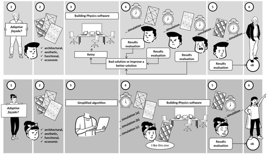
Figure 1.
Comparison between standard workflow (above) and workflow following the proposed simplified algorithm (below).
The research focuses on using steady-state calculation models required by the standards for calculating energy performance. The adaptive façade “adapts”, or better, “changes” its configuration according to the external climatic conditions, which depend on some variables, such as solar radiation in summer and winter, natural outdoor lighting and the level of indoor lighting. In this research, only the incident solar radiation was considered as the primary driving variable (being the one largely influencing the overall energy performance). The research focuses on how to manage the adaptive response capacity with the aim to evaluate the benefit of the shielding system on transparent, absorbing surfaces according to a simplified steady-state calculation model compliant with the ISO 13790 standard [72] and EN 52016 [17].
The paper structure includes the following sections corresponding to the main steps of the study: (a) methodology development, where the shielding system conceptualisation is described, and the genesis and the use of the algorithm for modelling and analysing the shielding system effects are explained; (b) applicative case study description, where a demo in a test room of a building located in Bologna is reported; (c) results discussion, where the outcomes are critically commented on to demonstrate the effectiveness of the proposed method with the support of evidence-based numerical results; and (d) conclusions.
3. Methodology
The starting position assumed as the design brief is to define a quick, time-saving, simplified method to investigate the main characteristics of an adaptive façade system based on modular elements able to comply with the different orientations of the building façades and considering the environmental condition variations. Accordingly, the methodology focuses on the key factors determining the energy performance of the façade following the ISO 13790 standard calculation algorithm. In other words, the research intends to translate the geometric configuration and the materials of the adaptive façade into the evaluation process based on standard calculation, working, in particular, on two factors:
- The shielding coefficient Fsh;
- The absorption factor α.
This allows for the determination of the thermal energy requirement, useful for summer cooling. Thus, the main aim is basically addressed to support the design conceptualisation for the summer period, although the possible impacts on the passive gains during the winter period are considered as well.
Methodologically speaking, the design phases can be listed as follows:
- Conceptualisation and definition of the geometry of the shielding system, of the technology and of the properties of the shielding materials;
- Calculation of the Fsh and α values related to the adaptive façade under investigation;
- Elaboration of a quick, time-saving algorithm for calculating energy needs for cooling (QC,gn) according to ISO 13790.
3.1. Conceptualisation and Definition of the Geometry of the Shielding System
The assumed design challenge is the definition of an adaptive building shell based on floor-to-floor modular panels replicated on the façades of a multi-storey building with a variable exposition to identify a flexible solution coherent with a relatively homogeneous architectural elevation layout.
The modules cover both the building’s transparent and opaque surfaces, which are assumed to be properly insulated and glazed. After some different possible configurations were explored, a few typologies were then selected to enter the simulation phase. During the process, some key elements were assumed as particularly relevant for both user preferences and indoor comfort:
- The module was required to have the same pattern in order to maintain the same aspect in the different façades, allowing a quite clear vision of the landscape in each direction;
- The module was expected to provide a good contribution to the opaque ventilated façade while ensuring adequate natural light levels inside the building when placed in front of the glazed surfaces;
- The module was supposed to be manually operated in a fully open position to allow a system override according to the occupants’ preferences (which is not the scope of the adaptive shell optimisation but is considered a priority by the end-users).
The final module is 3.2 m tall (assuming the supporting structure is fixed at the edge beam level of each floor) and 0.8 m long to make it easily operable in case of need (Figure 2). For the same reason, and to reduce the overall façade weight, each module is obtained by an aluminium frame (whose squared section hosts the actuators) supporting a perforated aluminium sheet with a pattern of circular openings in two different sizes. The larger one (0.08 m) hosts a rotating aluminium flap, which acts as an adaptable, dynamic element, and a smaller one is introduced to ensure adequate natural light levels and to balance the panel openness factor. Each flap can rotate on its vertical or horizontal axis depending on the façade orientation (horizontally in the south direction and vertically in the east or west direction). All the flaps in the same row or column are driven by the same actuator placed within the module framework.
The actuator is made of two springs, one conventional spring and one SMA spring. Shape memory alloys have the characteristic of deforming according to temperature variation, and the SMA spring works as an antagonist of the conventional one. When the temperature increases, the SMA spring is deformed, consequently compressing the second. This generates a rotation in the axis that connects all the same row or column flaps, which varies from an angle of 90° (open flaps) to an angle of 0° (closed flaps). The dynamism is fully controlled in a passive way depending on the solar radiation levels: as it varies, the orientation of the shielding system varies.

Figure 2.
Dimensions of the module, of the flaps and of the activation system according to façade orientation: horizontal rotation in the case of south orientation, vertical rotation in the case of east or west orientation. (Credits: Camilla Lucchetti and Cristian Montevecchi).
As Figure 2 summarises, the two adaptive modules are accompanied by a third module of corrugated metal sheet with the same pattern of flaps to be used on the north-oriented façades. This third typology can be moved manually, rotating on its side vertical axis, and is thought as a full blind device only.
As already mentioned, the side rotation of the whole module is also possible for the adaptive modules in case occupants need an override to obtain a full open view of the landscape.
The geometry of the different shielding configurations must be modelled considering the orientation of the façade (east, west, south) and the opening angle of the flaps (0°, 45° and 90°) for a total of nine possible configurations.
3.2. Calculation of the Fsh and α Values Related to the Adaptive Façade under Investigation
The shielding coefficient Fsh, calculated according to ISO 13790 [72], takes into account the open area for each of the three opening angles of the mobile elements of the façade according to the formula:
where:
Fsh = 100 − (Af/Ap) [m2]
Ap is the module area [m2];
Af is the area of the unshielded holes given by the Formula (2) [m2].
The area of the holes is given by
where:
Af = n × π × r2 [m2]
r is the radius of the moving part of the shield, in meters;
n is the number of moving parts of the shield.
The Fsh values are equal to 0.05 when the flap is rotated by 0°; 0.22 when the flap is rotated by 45°; and 0.62 when the flap is rotated by 90°. These values are used for calculation purposes.
Adaptive façade shielding transparent glazed surfaces—the role of Fsh value
The flaps’ rotation influences the shielding factor Fsh, which will necessarily vary depending on the period of the year and on the related solar radiation. For example, in August, Fsh << 1, while in January, Fsh = 1.
The flaps of each module can assume various configurations depending on the summer or winter regime as follows:
- -
- All closed (shielding is 100%);
- -
- All open (shielding is about 30%);
- -
- Flaps 45° rotated (the shielding is about 70%).
In winter, as there is no overheating risk, the number of total flaps opening will be assumed to maximise the natural light inflow.
The role of the modules is not only relevant in investigating the shielding capacity in front of the glazed surfaces, but also in understanding how much solar radiation is reflected when it is placed in front of the opaque wall.
Adaptive façade shielding transparent glazed surfaces—the role of α value
Similar to the Fsh factor, the absorption coefficient α must also be determined for the specific case based on the material of the shield (e.g., aluminium) and of the openings/holes.
The calculation of the absorption coefficient α takes into account the two materials that characterise the absorption of the shield:
- -
- The value of the material used (anodised aluminium) valid both for the panel (α1) and for the flaps (α2) and for which α1 = α2 = 0.14;
- -
- The value of the free holes with α3 = 1.
The coefficient αm is calculated with Formula (3):
αm = ((Ap − Af) × α1 + Af × α3)/Ap [−]
The values of αm are equal to αm = 0.186 for flaps rotated 0°, αm = 0.327 for flaps rotated 45° and αm = 0.669 for flaps rotated 90°. These values will be used for calculation purposes.
3.3. Elaboration of the Simplified Algorithm for the Calculation of QC,gn
The thermal energy needs in summer, according to ISO 13790, are calculated with Formula (4):
where:
QC,gn = Qint + Qsol [kWh]
Qint is the sum of the internal heat gains;
Qsol is the sum of the solar heat gains due to solar radiation.
As part of the simplified algorithm for calculating the contribution of the shielding system, we consider the internal contributions as constants, while the contributions due to solar radiation (Qsol) are calculated according to the Formula (5):
where:
Qsol = (Σk φsol,mn,k) t + [Σl (1 − btr,l) × φsol,mn,u,l] t [kWh]
φsol,mn,k is the time-average heat flow rate from solar heat source k, expressed in W, calculated according to Formula (6);
φsol,mn,u,l is the time-average heat flow rate from solar heat source l in the adjacent unconditioned;
space, expressed in watts (negligible in the case study);
btr,l is the adjustment factor for the adjacent unconditioned space with a heat source;
l, defined in ISO 13789 (negligible in the case study);
t is the time period of the considered month or season, expressed in megaseconds.
where:
φsol,k = Fsh,ob,k × Asol,k × Isol,k − Fr,k φr,k [W]
Fsh,ob,k is the shading factor of reduction for external obstacles for the effective solar collecting area of surface k;
Asol,k is the effective collecting area of the opaque and transparent surfaces k with a given orientation and angle of inclination in the considered area or space [m2];
Isol,k is the solar irradiance—the mean energy of solar radiation over the time interval—of the calculation, per square meter of collection area of the surface k, with a given orientation and angle of inclination [W/m2];
Fr,k φr,k is the additional heat flow due to the thermal radiation towards the sky from the building element k, expressed in watts (negligible in this specific study).
The catching area can refer to the opaque enclosure, according to Formula (7), and to the transparent enclosure, with Formula (8). In both formulas, the values of Fsh and αm are calculated as in the previous point
where:
Asol,op = αS,c × Rse × Uc × Ac [m2]
αS,c is the dimensionless absorption coefficient to solar radiation of the opaque element [−];
Rse is the external surface heat resistance of the opaque part, determined according to ISO 6946 [77] [m2 K/W];
Uc is the thermal transmittance of the opaque element [W/m2 K];
Ac is the surface of the opaque part, expressed in square meters [m2].
where:
Asol,w = Fsh,gl × ggl × (1 − FF) × Aw,p [m2]
Fsh,gl is the shading reduction factor due to the shielding effect on the absorbing element [−];
ggl is the total solar energy transmittance of the transparent part of the glass element (solar factor) [−];
FF is the frame area fraction given by the ratio between the area of the frame (At) and the area of the glazed part Av, calculated as FF = At/Av [−];
Aw,p is the area of the transparent surface of the window in m2 (glazed surface).
The application of the calculation algorithm allows for the estimation (for each module) of the amount of energy needed for cooling (QC,gn) for a single panel.
The “Results” section describes the outcomes of the application of the algorithm to the geometry of the module described in the conceptualisation section. The algorithm and its simplification criteria can be applied to any other geometry.
3.4. Strengths and Limitations
The proposed methodology investigates the key parameters through equations that can be easily implemented in an Excel file to make the input data process easier and faster. This is the main strength of the process, which reduces the time for both the modelling and the computation compared to the time-consuming performances from the literature. The process allows for an easy check of data and can be divided into sub-sections to make the control of more complex configurations easier. Additionally, the use of Excel does not require particularly qualified users, strongly reducing the training time, which is not usually accounted for as a primary resource in the evaluation process and which, instead, is of great relevance in conventional professional conditions of architectural studios.
The study does not focus on the technological and structural implications of the module and of the adaptive solution. Although some preliminary analyses were performed to ensure the solution could be properly implemented and supported by the substructures, these aspects are not reported in the paper, which only explores the definition of shielding pattern in relation to solar radiation levels. Maintenance and management aspects are not investigated in detail for the same reasons, although the choice to proceed with passive actuators clearly suggests the preference for a system which does not require periodic actions to be totally self-sufficient and embedded in the module frame. Furthermore, it has to be remarked that the calculation of the energy loads does not consider the embodied energy of components and systems which belong to the very specific field of the LCA approach and whose contribution would affect the building envelope anyway and would not be strictly influenced by the adaptive nature of the proposed solution.
The possible effect on the outdoor microclimate, derived by a difference of albedo, was not considered in this research because the study was not focused on this specific scope.
4. Applicative Case Study
The time-saving calculation algorithm described in the methodology was applied to a test room of a residential building located in Bologna. As anticipated in the conceptualisation section, the main objective was to provide an effective adaptive shielding system able to consider the different façade orientations without drastically changing the layout and pattern of the modules within the building elevations.
The test room was located in Bologna, Italy. The city of Bologna (see Figure 3) is located in the north of Italy, 50 m above sea level, classified E according to the Italian climatic zones (DPR 26/08/1993 n.412) with 2502 day degree. The city is characterised by a humid–temperate climate, classified as marine climate subtype Cfb according to the Koppen scale [78,79] with hot humid summers and cold rigid winters. According to ASHRAE 169 [80] classification, the heating degree days (HDD) of Bologna are 2259.
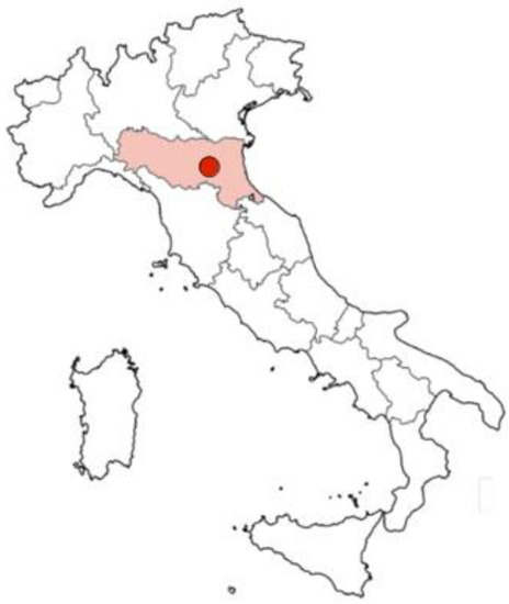
Figure 3.
Bologna location within Emilia Romagna region in Italy.
As Figure 4 suggests, the building is articulated in differently oriented volumes due to the plot constraints and alignment determined by the development plan of the site. However, one of the key points in the design brief was to possibly provide a homogeneous layout of the elevations, ensuring the privacy of dwellings facing each other and considering the surrounding buildings while maximising the view towards the landscape. These limitations and requests influenced the preliminary definition of the adoptable shielding systems, leading us to choose the flat modular second skin described in the conceptualisation section.
According to the typical plan layout, a test room (Figure 5 and Table 1) of 3.7 × 4 m with 2.7 m height was defined, and it was assumed to be exposed with one side to the external environment in three possible alternative configurations: south, west and east orientations.
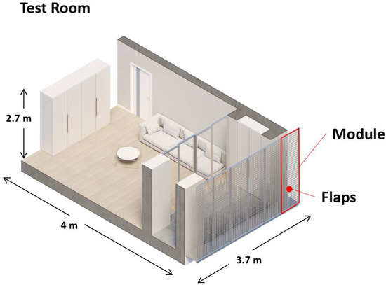
Figure 5.
Typical plan test room.

Table 1.
Room heat transfer coefficients.

Figure 4.
General view of the building articulated in differently oriented volumes for which a homogeneous façade layout was required.
The glazed surface was shielded by the modular adaptive elements, and the three orientations were considered for calculation purposes, assuming the rotation of flaps corresponding to 0°, 45° and 90°, adopting the related Fsh and α values, for a total of nine possible combinations.
5. Results
This section reports the implementation of the proposed methodology in the applicative case study concerning the design solution described in the conceptualisation section applied to the test room. In particular, the results are related to:
- -
- Energy needs for cooling (Qc,gn), which vary according to the orientation and the rotation of the flaps;
- -
- Evaluation of the operating time range of the SMA actuator.
5.1. Energy Need for Cooling Correlated to Test-Room Orientation and Flap Rotation Angles
Regarding energy needs for cooling, Table 2 shows that—in the case of east-oriented modules—the heat flow from solar radiation φsol varies according to the flaps’ rotation angle from a maximum of 7089 kWh with a 90° rotation to a minimum of 636 kWh with a 0° rotation, corresponding to a shielding module completely closed and a 92% reduction in the load due to solar radiation. A reduction of 64% is obtained in the case of 45° rotation.
Very closed proportions are also maintained for the west- and south-oriented modules, with slightly higher values due to the different incident solar radiation with reference to the chosen location.
The results demonstrate that the simplified algorithm can determine the variation in heat contributions due to solar radiation based on the opening level of the shielding flaps.
Table 2.
Resulting solar gains (Qc,gn) with shielding modules oriented to East, South and West according to the three rotation angles of the flaps.
Table 2.
Resulting solar gains (Qc,gn) with shielding modules oriented to East, South and West according to the three rotation angles of the flaps.
| Façade Orientation | EAST | SOUTH | WEST | ||||||
|---|---|---|---|---|---|---|---|---|---|
| Flap Rotation Angle | 90° | 45° | 0° | 90° | 45° | 0° | 90° | 45° | 0° |
| Qc,gn | 9422 | 4893 | 2970 | 12,685 | 6071 | 3263 | 13,170 | 6246 | 3307 |
| Qint | 2333 | 2333 | 2333 | 2333 | 2333 | 2333 | 2333 | 2333 | 2333 |
| Φsol | 7088 | 2559 | 636 | 10,352 | 3738 | 930 | 10,836 | 3912 | 973 |
5.2. Evaluation of the Operating Time Range of the SMA Actuator
The calculation algorithm allows the setting of the opening of the shielding flaps in relation to the incident solar radiation that hits the SMA actuator. According to the available literature on SMA-based solutions [45,81], an actuator operating in a range between 170 W/m2 and 350 W/m2 is adopted. These values determined the rotation angle of the flaps. In particular, it was established that:
- -
- If the solar radiation is less than 170 W/m2, the flaps are fully open, corresponding to a 90° rotation angle and, accordingly, the reduction factor Fsh is 0.62;
- -
- If the solar radiation is more than 350 W/m2, the flaps are closed, corresponding to a 0° rotation angle and, accordingly, the reduction factor Fsh is 0.05;
- -
- If the solar radiation is more than 350 W/m2, but less than 170 W/m2, the flaps are semi-open, corresponding to a 45° rotation angle and, accordingly, the reduction factor Fsh is 0.22;
Assuming these conditions, the daily operating hours (6:00–20:00) have been simulated for four days particularly representative of the seasonal trends: 20th March (equinox); 2nd June (summer solstice); 21st December (winter solstice); and the hottest day of the year according to local climate data set, namely 29th July.
On 20th March (equinox—Figure 6a), between 6 and 10 in the morning, the east-oriented façade is exposed to solar radiation that is less than 170 W/m2 and, consequently, the flaps assume a fully open configuration (90° rotation) to allow for maximum heat and natural light inflow. From 11 to 16, they rotate to a 45° position to reduce the solar radiation, whose intensity in the considered time interval is between 170 W/m2 and 350 W/m2. From 17, when the solar radiation intensity is less than 170 W/m2, the flaps rotate to a 90° position, back to the fully open configuration. On the same day, for the west-facing façade, from 6 to 11 in the morning, the flaps adopt the same fully open configuration, shifting to the 45° and 90° rotations between 12 and 18 due to the increase in incident solar radiation and, of course, a completely closed configuration during the sunset to return to a fully open configuration after 19.
The south-oriented façade assumes a fully open configuration (90° rotation) between 6 and 10 in the morning, shifting to a 45° rotation around 11 to finally assume the completely closed configuration (0° rotation) during the hottest hours of the day between 12 and 15. During the afternoon, when the solar radiation moves in the west direction, the flaps progressively turn into the semi-open and fully open configurations between 16 and 17.
On 21th June (summer solstice—Figure 6b), between 7 and 8 in the morning, immediately after the sun has just risen, the east-oriented façade rapidly moves from a fully open to a semi-open configuration in response to the increase in the solar radiation, which perpendicularly hits the surface from around 9 until 11, when the flaps rotate to a 0° position in order to completely shield the surface and avoid unsuitable passive gains. From 12 to 17, the flaps rotate to a 45° semi-open configuration in response to less intense radiation and finally assume a fully open configuration after 18. The west façade configuration varies during the first half of the day between a fully open and a semi-open condition, finally shifting to a completely closed one after 14 when the intensity of solar radiation increases and stays above 350 W/m2. The graph representing the south façade shows a symmetrical layout describing how, in the hottest hours of the day between 11 and 15, the flaps assume a completely closed configuration (0° rotation) with 2 h of semi-open 45° flap position immediately before and after (during 9–10 and 16–17 time intervals, respectively). During early morning and late afternoon, the façade is, instead, in a fully open configuration.
On the day of 29th July (the hottest day of the year according to a historic dataset—Figure 6d) on the east façade, when the sun has just risen, between 6 and 8 in the morning, the flaps are open and rotated by 90°. From 10 to 12, the flaps are completely closed as the solar radiation impacts the façade perpendicularly, and it is, therefore, necessary to completely shield the surface to minimise solar gains. From 13 to 17, the flaps assume a 45° semi-open configuration, shifting to a fully open one around 18, when the solar radiation mainly hits in the west direction. The west façade assumes fully and semi-open configurations during the first part of the day; from 6 to 13, the flaps are 90° and then 45° rotated. From 14, however, it is necessary to completely shield the surface, and the flaps move to a 0° rotation angle. From 20, when the solar radiation is less than 170 W/m2, the flaps rotate again to a fully open configuration (90° rotation). The south-oriented façade assumes a completely closed configuration during the hottest hours of the day, from 11 to 16, with a slightly asymmetrical 45° semi-open configuration period before and after, corresponding to 9–10 and 17 time intervals. In the remaining time slots, the flaps assume a fully open configuration.
During the whole day of 21st December (winter solstice—Figure 6d), the east-oriented façade requires the flaps to assume a fully open configuration (90° rotation) to ensure the maximisation of heat and natural light inflow; the same can be said for the west-oriented façade except for the time slots between 12 and 16, where the solar radiation is almost perpendicular, and the flaps rotate to a 45° semi-open configuration. The same can be said for the south façade in the time range between 14 and 16. Considering the fact that the intensity of solar radiation during the wintertime is lower, it never exceeds 350 W/m2, there is no need to assume a completely closed configuration (0° rotation) of the shielding elements.


Figure 6.
Operating times of the shielding flaps according to façade orientation, daytime and period of the year. Axis x = daytime, axis y = reduction/shielding factor Fsh. (a) spring and autumn equinox, (b) summer solstice, (c) the hottest day of the year and (d) winter solstice.
6. Discussion
The results achieved by adopting the proposed simplified methodology allow us to properly consider the influence of the investigated parameters in defining the functional characteristics of the adaptive modules and their impacts on the building envelope’s performances. Despite the assumed simplification, it is possible to properly assess the solution’s effectiveness, quantifying the impacts and the operating settings as well as evaluating the responsiveness of the façade’s architectural layout.
The main scope of the study was, however, to demonstrate that these outcomes could be achieved by reducing the time usually required by software simulations.
The preparation of the Excel file according to the methodology required 1.5 h, and the input data process required 3.5 h, for a total time to insert data equal to 5 h and was performed by two junior researchers not specifically trained (training time equal to 0 h) for the purpose but fond of architectural technologies and building energy performance principles. Moreover, the computation time for Excel is nearly 0 h. The technical solution for the adaptive façade was previously defined and provided to the tester as one of the possible alternatives to be explored without any changes being made. Once the input data phase was completed, although the results were immediately available in the Excel file, an extra half an hour was added to check their consistency and to generate the graphical output. Thus, the total time required by the simplified methodology was approximately half a day (approximately 5.5 h.).
As the scientific literature does not provide comparative studies on time performances or on overall time demand for the process, only information on the time of specific analysis, the simplified algorithm was tested against a simulation software assessing the same technical solution.
Two junior researchers, trained in the basic use of the simulation software IES.VE [82], were involved and were asked to model the solution according to the level of detail reported in Figure 2 with reference to the test-room conditions of Figure 5 and Table 1. The test bed site location was assumed the same, and all other parameters were set accordingly. It must be remarked that the scope was not to compare the results (whose level of detail is completely different) but to compare the time required for performing each process. The choice of the software, among the many possible choices in the market, was reliant to the tester’s availability, skills, knowledge and background. The process can be replicated with other commercial products but, on average, the overall time difference is negligible.
The modelling phase meant that the time to insert data required two working days of 8 h, and the computation time was about 1 h. In addition, a past training session of five 4 h slots for each tester was to be considered. The process required a total of 37 h. Each of the two processes was assigned to two people separately, but the time required was almost aligned. Table 3 reports a comparison following SUCA criteria.
Table 3.
Comparison between simplified algorithm, with Excel software, and IES.VE for each SUCA criterion.
Considering that the case study was not particularly complex and the configuration was predefined, the time saved was about 86% and can become even higher in more articulated solutions where both the modelling and computation time are longer. Even without considering the training time required for the simulation software, the saving is about 71%.
7. Conclusions
The simplified calculation algorithm allows us to estimate the effectiveness of the shielding system considering the effects on energy needs (Table 1) and to predict the activation times of the shielding system based on the selected representative days, depending on the orientation of the façade.
The research, applied to a specific case study but replicable in any other context, provides professionals, both the ones involved in the overall building design and those involved in shielding systems, with valuable elements to evaluate whether the investigated option meets the project requirements at an architectural (design and texture) level; a technological/functional (implementation and activation methods) level; and an energy demand (energy saving contribution) level.
The authors are aware that more detailed approaches and the use of dynamic software modelling are needed to fully define the solution deeply considering the effects on the energy demand; however, they are significantly demanding in terms of time and resources needed to be invested for calculation purposes. Therefore, the ambition of the proposed methodology is not to replace these tools but to offer an alternative and rapid approach for the early design stage when alternative options are still on the table and it is not sustainable to undergo in-depth, time-consuming, costly evaluations for all of them with the risk that many are ultimately proven to be ineffective.
The role of the proposed algorithm is to support the initial stage selection of the most promising design solution, i.e., deciding upon a squared or circular shape of the adaptive flaps (or whatever the adaptive system is) or exploring different sizes, leaving their in-depth analysis and dynamic modelling to a further stage.
Author Contributions
Conceptualization, J.G. and K.F.; methodology, J.G. and K.F.; software, K.F.; validation, J.G. and K.F.; formal analysis, K.F.; investigation, J.G. and K.F.; data curation, J.G.; writing—original draft preparation, J.G. and K.F.; writing—review and editing, J.G. and K.F.; supervision, J.G.; project administration, J.G. All authors have read and agreed to the published version of the manuscript.
Funding
This research received no external funding.
Data Availability Statement
Not applicable.
Conflicts of Interest
The authors declare no conflict of interest.
References
- Monzón-Chavarrías, M.; López-Mesa, B.; Resende, J.; Corvacho, H. The NZEB Concept and Its Requirements for Residential Buildings Renovation in Southern Europe: The Case of Multi-Family Buildings from 1961-1980 in Portugal and Spain. J. Build. Eng. 2020, in press. [Google Scholar] [CrossRef]
- IPCC. Summary for Policymakers. In Global Warming of 1.5°C. An IPCC Special Report on the Impacts of Global Warming; IPCC: Geneva, Switzerland, 2018; ISBN 9789291691517. [Google Scholar]
- Devès, M.H.; Lang, M.; Bourrelier, P.; Valérian, F. Why the IPCC Should Evolve in Response to the UNFCCC Bottom-up Strategy Adopted in Paris? An Opinion from the French Association for Disaster Risk Reduction. Environ. Sci. Policy 2017, 78, 142–148. [Google Scholar] [CrossRef]
- Rogelj, J.; Shindell, D.; Jiang, K.; Fifita, S.; Forster, P.; Ginzburg, V.; Handa, C.; Kheshgi, H.; Kobayashi, S.; Kriegler, E.; et al. Mitigation Pathways Compatible with 1.5°C in the Context of Sustainable Development. In Global Warming of 1.5°C. An IPCC Special Report on the Impacts of Global Warming of 1.5°C above Pre-Industrial Levels and Related Global Greenhouse Gas Emission Pathw; IPCC: Geneva, Switzerland, 2018; p. 82. [Google Scholar]
- Selkowitz, S.; Head, D.; Aschehoug, Ø.; Lee, E.S. Advanced Interactive Facades-Critical Elements for Future Green Buildings? In Proceedings of the Annual USGBC International Conference and Expo, Pittsburgh, PA, USA, 12–14 November 2003.
- Gaspari, J. Climate Responsive Building Envelope. From Façade Shading Systems to Adaptive Shells; Franco Angeli, Ed.; Milano: Milan, Italy, 2020. [Google Scholar]
- Loonen, R.C.G.M.; Trčka, M.; Cóstola, D.; Hensen, J.L.M. Climate Adaptive Building Shells: State-of-the-Art and Future Challenges. Renew. Sustain. Energy Rev. 2013, 25, 483–493. [Google Scholar] [CrossRef]
- Wigginton, M.; Harris, J. Intelligent Skins; Routledge: London, UK, 2013; ISBN 9781136394867. [Google Scholar]
- Michael, W.; Jude, H. Intelligent Skins; Architectural Press: London, UK, 2002. [Google Scholar]
- Basurto, C.; Kämpf, J.H.; Scartezzini, J.-L. Multi-Criteria Analysis for the Integrated Performance Assessment of Complex Fenestration Systems. Build. Res. Inf. 2017, 45, 926–942. [Google Scholar] [CrossRef]
- Fattahi Tabasi, S.; Banihashemi, S. Design and Mechanism of Building Responsive Skins: State-of-the-Art and Systematic Analysis. Front. Archit. Res. 2022, in press. [Google Scholar] [CrossRef]
- Doumpioti, C.; Greenberg, E.L.; Karatzas, K. Embedded Intelligence: Material Responsiveness in Façade Systems. In On Responsive Information and Variations in Architecture—Proceedings of the 30th Annual Conference of the Association for Computer Aided Design in Architecture; ACADIA: Wolfville, NS, Canada, 2010. [Google Scholar]
- Doumpioti, C. Responsive and Autonomous Material Interfaces. In Integration Through Computation—Proceedings of the 31st Annual Conference of the Association for Computer Aided Design in Architecture; ACADIA: Wolfville, NS, Canada, 2011. [Google Scholar]
- Fox, M.A.; Yeh, B.P. Intelligent Kinetic Systems in Architecture. In Managing Interactions in Smart Environments; Springer: Berlin/Heidelberg, Germany, 2000; pp. 91–103. [Google Scholar] [CrossRef]
- Nicol, J.F.; Humphreys, M.A. Adaptive Thermal Comfort and Sustainable Thermal Standards for Buildings. Energy Build 2002, 34, 563–572. [Google Scholar] [CrossRef]
- Yi, H.; Kim, Y. Prototyping of 4D-Printed Self-Shaping Building Skin in Architecture: Design, Fabrication, and Investigation of a Two-Way Shape Memory Composite (TWSMC) Façade Panel. J. Build. Eng. 2021, 43, 103076. [Google Scholar] [CrossRef]
- ISO 52016-1; Energy Performance of Buildings—Energy Needs for Heating and Cooling, Internal Temperatures and Sensible and Latent Beat Loads—Part 1: Calculation Procedures. ISO: Geneva, Switzerland, 2017.
- Ramzy, N.; Fayed, H. Kinetic Systems in Architecture: New Approach for Environmental Control Systems and Context-Sensitive Buildings. Sustain. Cities Soc. 2011, 1, 170–177. [Google Scholar] [CrossRef]
- Addington, M.; Schodek, D. Smart Materials and New Technologies; Architectu: Oxford, UK, 2005; Volume 148. [Google Scholar]
- Cattaruzzi, J.; Gaspari, J. Taxonomical Investigation of Self-Sufficient Kinetic Building Envelopes. J. Archit. Eng. 2021, 27, 1–15. [Google Scholar] [CrossRef]
- Abdullah, Y.S.; Al-Alwan, H.A. Smart material systems and adaptiveness in architecture. Ain Shams Eng. J. 2019, 10, 623–638. [Google Scholar] [CrossRef]
- Fiorito, F.; Sauchelli, M.; Arroyo, D.; Pesenti, M.; Imperadori, M.; Masera, G.; Ranzi, G. Shape Morphing Solar Shadings: A Review. Renew. Sustain. Energy Rev. 2016, 55, 863–884. [Google Scholar] [CrossRef]
- Pesenti, M.; Masera, G.; Fiorito, F. Exploration of Adaptive Origami Shading Concepts through Integrated Dynamic Simulations. J. Arch. Eng. 2018, 24, 323. [Google Scholar] [CrossRef]
- Pesenti, M.; Masera, G.; Fiorito, F.; Sauchelli, M. Kinetic Solar Skin: A Responsive Folding Technique. In Energy Procedia; Elsevier: Amsterdam, The Netherlands, 2015. [Google Scholar]
- Yi, H.; Kim, D.; Kim, Y.; Kim, D.; Koh, J.; Kim, M.-J. 3D-Printed Attachable Kinetic Shading Device with Alternate Actuation: Use of Shape-Memory Alloy (SMA) for Climate-Adaptive Responsive Architecture. Autom. Constr. 2020, 114, 103151. [Google Scholar] [CrossRef]
- Luible, A.; Gosztonyi, S.; Overend, M.; Aelenei, L.; Krstic-Furundzic, A.; Perino, M.; Goia, F.; Wellershoff, F.; Attia, S.; Pottgiesser, U.; et al. Facade 2018-Adaptive! TU Delft: Delft, The Netherlands, 2018. [Google Scholar]
- Sun, L.; Lu, L.; Yang, H. Optimum Design of Shading-Type Building-Integrated Photovoltaic Claddings with Different Surface Azimuth Angles. Appl. Energy 2012, 90, 233–240. [Google Scholar] [CrossRef]
- Sun, L.L.; Yang, H.X. Impacts of the Shading-Type Building-Integrated Photovoltaic Claddings on Electricity Generation and Cooling Load Component through Shaded Windows. Energy Build 2010, 42, 455–460. [Google Scholar] [CrossRef]
- Pasold, A.; Foged, I.W. Performative Responsive Architecture Powered by Climate; ACADIA: Wolfville, NS, Canada, 2010. [Google Scholar]
- Schleicher, S.; Lienhard, J.; Poppinga, S.; Masselter, T.; Speck, T.; Knippers, J. Adaptive Façade Shading Systems Inspired by Natural Elastic Kinematics Botany and Paleobotany View Project Adaptive Facades View Project. In Proceedings of the International Adaptive Architecture Conference IAAC (2011), London, UK, 3 March 2011. [Google Scholar]
- Khoo, C.K.; Salim, F. Responsive Materiality for Morphing Architectural Skins; ACADIA: Wolfville, NS, Canada, 2013. [Google Scholar]
- Persiani, S.G.L.; Battisti, A.; Wolf, T. Autoreactive Architectural Facades—Discussing Unpowered Kinetic Building Skins and the Method of Evolutionary Optimization. In Proceedings of the 11th Conference on Adaptive Building Skins, Bern, Switzerland, 28–29 October 2016. [Google Scholar]
- Persiani, S.G.L.; Molter, P.L.; Aresta, C.; Klein, T. Mapping of Environmental Interaction and Adaptive Materials for the Autoreactive Potential of Building Skins. In Proceedings of the 41st IAHS World Congress Sustainability and Innovation for the Future, Albufeira, Portugal, 13–16 September 2016. [Google Scholar]
- Loonen, R.; Rico-Martinez, J.M.; Favoino, F.; Marcin, B.; Ménézo, C.; la Ferla, G.; Aelenei, L. Design for Façade Adaptability: Towards a Unified and Systematic Characterisation. In Proceedings of the 10th Conference on Advanced Building Skins, Bern, Switserland, 3–4 November 2015; pp. 1284–1294. [Google Scholar]
- Aresta, C. Temperature-Responsive Systems: Passive Strategies for Building Envelopes. In Proceedings of the FAÇADE 2018—Final Conference of COST TU1403 “Adaptive Facades Network”, Lucerne, Switzerland, 26–27 November 2018. [Google Scholar]
- Yoon, J. Climate-Adaptive Facade Design with Smart Materials: Evaluation and Strategies of Thermo-Responsive Smart Material Applications for Building Skins in Seoul; PLEA: Hong Kong, China, 2018. [Google Scholar]
- Yoon, J. SMP Prototype Design and Fabrication for Thermo-Responsive Façade Elements. J. Facade Des. Eng. 2019, 7, 41–61. [Google Scholar] [CrossRef]
- Heo, Y.; Choudhary, R.; Augenbroe, G.A. Calibration of Building Energy Models for Retrofit Analysis under Uncertainty. Energy Build 2012, 47, 550–560. [Google Scholar] [CrossRef]
- Li, J.; Duan, Q.; Zhang, E.; Wang, J. Applications of Shape Memory Polymers in Kinetic Buildings. Adv. Mater. Sci. Eng. 2018, 2018, 1–13. [Google Scholar] [CrossRef]
- Holstov, A.; Bridgens, B.; Farmer, G. Hygromorphic Materials for Sustainable Responsive Architecture. Constr. Build Mater. 2015, 98, 570–582. [Google Scholar] [CrossRef]
- Reichert, S.; Menges, A.; Correa, D. Meteorosensitive architecture: Biomimetic building skins based on materially embedded and hygroscopically enabled responsiveness. Comput. Des. 2015, 60, 50–69. [Google Scholar] [CrossRef]
- Holstov, A.; Farmer, G.; Bridgens, B. Sustainable Materialisation of Responsive Architecture. Sustainability 2017, 9, 435. [Google Scholar] [CrossRef]
- El-Dabaa, R.; Abdelmohsen, S. HMTM: Hygromorphic-Thermobimetal Composites as a Novel Approach to Enhance Passive Actuation of Adaptive Façades. In Proceedings of the 18th CAAD Futures 2019 International Conference, Daejeon, Korea, 26–28 June 2019. [Google Scholar]
- Vazquez, E.; Randall, C.; Duarte, J.P. Shape-Changing Architectural Skins A Review on Materials, Design and Fabrication Strategies and Performance Analysis. J. Facade Des. Eng. 2019, 7, 93–114. [Google Scholar]
- Formentini, M.; Lenci, S. An Innovative Building Envelope (Kinetic Façade) with Shape Memory Alloys Used as Actuators and Sensors. Autom. Constr. 2018, 85, 220–231. [Google Scholar] [CrossRef]
- Barozzi, M.; Lienhard, J.; Zanelli, A.; Monticelli, C. The Sustainability of Adaptive Envelopes: Developments of Kinetic Architecture. In Procedia Engineering; Springer: Berlin/Heidelberg, Germany, 2016. [Google Scholar]
- Ricci, A.; Ponzio, C.; Fabbri, K.; Gaspari, J.; Naboni, E. Development of a self-sufficient dynamic façade within the context of climate change. Arch. Sci. Rev. 2020, 64, 87–97. [Google Scholar] [CrossRef]
- Ricci, A. Adaptive Building Envelope Design. Impatcs on Indoor Comfort of a Hostel in Bologna (Progetto Di Un Involucro Adattivo. Effetti Sul Comfort Indoor Di Un Edificio Adibito Ad Ostello a Bologna); University of Bologna: Bologna, Italy, 2018. [Google Scholar]
- Bakker, L.G.; Hoes-van Oeffelen, E.C.M.; Loonen, R.C.G.M.; Hensen, J.L.M. User Satisfaction and Interaction with Automated Dynamic Facades: A Pilot Study. Build Environ. 2014, 78, 44–52. [Google Scholar] [CrossRef]
- Khoo, C.K.; Burry, J.; Burry, M. Soft Responsive Kinetic System. In Proceedings of the 31st Annual Conference of the Association for Computer Aided Design in Architecture (ACADIA), Banff, AB, Canada, 13–16 October 2011. [Google Scholar]
- López, M.; Rubio, R.; Martín, S.; Croxford, B. How plants inspire façades. From plants to architecture: Biomimetic principles for the development of adaptive architectural envelopes. Renew. Sustain. Energy Rev. 2017, 67, 692–703. [Google Scholar] [CrossRef]
- Correa, D.; Augustin, N. Developing Climate-Responsive Envelopes with the Hygroscopic Motion of Wood Veneer. In Proceedings of the International Conference on Emerging Technologies in Architectural Design, Toronto, ON, Canada, 17–19 October 2019. [Google Scholar]
- Molter, P.; Bonnet, C.; Wagner, T.; Reifer, M.; Klein, T. Autoreactive Components in Double Skin Facades. In Proceedings of the 12th Conference on Advanced Building Skins, Bern, Switzerland, 2–3 October 2017; pp. 133–141. [Google Scholar]
- Barrett, R.M.; Barrett, R.P. Thermally Adaptive Building Coverings Inspired by Botanical Thermotropism. In Proceedings of the ASME 2016 Conference on Smart Materials, Adaptive Structures and Intelligent Systems, Stowe, VT, USA, 28 September 2016. [Google Scholar]
- Abdelmohsen, S.; Massoud, P.; Bahaa El-Dabaa, R.; Mokbl, T. A Computational Method for Tracking the Hygroscopic Motion of Wood to Develop Adaptive Architectural Skins, The Socio-Cultural Context of the Design Process View Project Measuring and Monitoring the Future “Greening” of the Middle East View Project. In Proceedings of the 36th Annual Conference on Education and Research in Computer Aided Architectural Design in Europe (eCAADe 2018), Łódź, Poland, 17–21 September 2018. [Google Scholar]
- Anis, M. Designing an Adaptive Building Envelope for Warm-Humid Climate with Bamboo Veneer as a Hygroscopically Active Material. In Proceedings of the ARCC 2019 International Conference, Toronto, ON, Canada, 29 May–1 June 2019. [Google Scholar]
- Lignarolo, L.; Lelieveld, C.; Teuffel, P. Shape Morphing Wind-Responsive Facade Systems Realised with Smart Materials. In Proceedings of the Adaptive Architecture: An International Conference, London, UK, 3–5 March 2011. [Google Scholar]
- Drozdowski, Z. The Adaptive Building Initiative: The Functional Aesthetic of Adaptivity. Archit. Des. 2011, 81, 118–123. [Google Scholar] [CrossRef]
- Moloney, J. Designing Kinetics for Architectural Facades State Change; Routledge: London, UK, 2011. [Google Scholar]
- Elghazi, Y.S. Modelling and Simulation of Integrated Responsive Solar-Shading with Double Skin Facades in Hot Arid Climates. In Proceedings of the BSO 2018: 4th Building Simulation and Optimization Conference, Cambridge, UK, 11–12 September 2018. [Google Scholar]
- Dewidar, K.M.; Mohamed, N.M.; Ashour, Y.S.; Dewidar, K.M.; Mohamed, N.M.; Ashour, Y.S. Living Skins: A New Concept of Self Active Building Envelope Regulating Systems. In Proceedings of the SB 13 Dubahi, Dubahi, United Arab Emirates, 8–10 December 2013. [Google Scholar]
- Negendahl, K.; Nielsen, T.R. Building Energy Optimization in the Early Design Stages: A Simplified Method. Energy Build 2015, 105, 88–99. [Google Scholar] [CrossRef]
- Strelitz, Z. Tall Building Design and Sustainable Urbanism: London as a Crucible. Intell. Build. Int. 2011, 3, 250–268. [Google Scholar] [CrossRef]
- Lv, Y.; Yao, H.; Li, A.; Yi, Q.; Janke, D.; Amon, T.; DS Quoie, G., Jr.; Shen, X.; Long, Z. Comparison of Simulation Methods for Dynamic Internal Air Distribution in Naturally Ventilated Livestock Buildings. Comput. Electron. Agric. 2022, 202, 107427. [Google Scholar] [CrossRef]
- Zheng, Z.; Chen, J.; Luo, X. Parallel Computational Building-Chain Model for Rapid Urban-Scale Energy Simulation. Energy Build 2019, 201, 37–52. [Google Scholar] [CrossRef]
- Foncubierta Blázquez, J.L.; Rodríguez Maestre, I.; González Gallero, F.J.; Mena Baladés, J.D. Reduction of Computation Time in Building Energy Performance Simulation Programs by Applying Tearing Techniques. Energy Build 2016, 130, 667–675. [Google Scholar] [CrossRef]
- Magni, M.; Ochs, F.; de Vries, S.; Maccarini, A.; Sigg, F. Detailed cross comparison of building energy simulation tools results using a reference office building as a case study. Energy Build. 2021, 250, 111260. [Google Scholar] [CrossRef]
- Hong, T.; Chou, S.K.; Bong, T.Y. Building Simulation: An Overview of Developments and Information Sources. Build Environ. 2000, 35, 347–361. [Google Scholar] [CrossRef]
- Magni, M.; Ochs, F.; Streicher, W. Comprehensive Analysis of the Influence of Different Building Modelling Approaches on the Results and Computational Time Using a Cross-Compared Model as a Reference. Energy Build 2022, 259, 111859. [Google Scholar] [CrossRef]
- Crawley, D.B.; Hand, J.W.; Kummert, M.; Griffith, B.T. Contrasting the Capabilities of Building Energy Performance Simulation Programs. Build Environ. 2008, 43, 661–673. [Google Scholar] [CrossRef]
- Elhadad, S.; Radha, C.H.; Kistelegdi, I.; Baranyai, B.; Gyergyák, J. Model Simplification on Energy and Comfort Simulation Analysis for Residential Building Design in Hot and Arid Climate. Energies 2020, 13, 1876. [Google Scholar] [CrossRef]
- ISO 13790:2008; Energy Performance of Buildings Calculation of Energy Use for Space Heating and Cooling. ISO: Geneva, Switzerland, 2008.
- Fabbri, K.; Gaspari, J.; Bartoletti, S.; Antonini, E. Effect of facade reflectance on outdoor microclimate: An Italian case study. Sustain. Cities Soc. 2020, 54, 101984. [Google Scholar] [CrossRef]
- Gaspari, J.; Fabbri, K.; Gabrielli, L. A Study on Parametric Design Application to Hospital Retrofitting for Improving Energy Savings and Comfort Conditions. Buildings 2019, 9, 220. [Google Scholar] [CrossRef]
- Fabbri, K.; Gaspari, J. A Replicable Methodology to Evaluate Passive Façade Performance with SMA during the Architectural Design Process: A Case Study Application. Energies 2021, 14, 6231. [Google Scholar] [CrossRef]
- Fabbri, K.; Gaspari, J.; Felicioni, L. Climate Change Effect on Building Performance: A Case Study in New York. Energies 2020, 13, 3160. [Google Scholar] [CrossRef]
- ISO 6946:2017; Building Components and Building Elements—Thermal Resistance and Thermal Transmittance—Calculation Methods. ISO: Geneva, Switzerland, 2017.
- Kottek, M.; Grieser, J.; Beck, C.; Rudolf, B.; Rubel, F. World Map of the Koppen- Geiger Climate Classification Updated. Meteorol. Z. 2006, 15, 259–263. [Google Scholar] [CrossRef]
- Köppen, W.; Geiger, R. Das Geographische System Der Klimate. Handb. Klimatol. 1936, 59, 7–30. [Google Scholar] [CrossRef]
- ANSI/ASHRAE Standard 169-2013; Climatic Data for Building Design Standards. ASHRAE: Peachtree Corners, GA, USA, 2013.
- Vercesi, L.; Speroni, A.; Mainini, A.G.; Poli, T. A Novel Approach to Shape Memory Alloys Applied to Passive Adaptive Shading Systems. J. Facade Des. Eng. 2020, 8, 43–64. [Google Scholar] [CrossRef]
- IES.VE. Integrated Environmental Solutios. Available online: https://www.iesve.com/ (accessed on 28 October 2022).
Publisher’s Note: MDPI stays neutral with regard to jurisdictional claims in published maps and institutional affiliations. |
© 2022 by the authors. Licensee MDPI, Basel, Switzerland. This article is an open access article distributed under the terms and conditions of the Creative Commons Attribution (CC BY) license (https://creativecommons.org/licenses/by/4.0/).