Article

Novel Hydraulic and Aerodynamic Schemes of Coil Type Steam Generator: A Mathematical Model and Experimental Data

by
Sulpan Kuskarbekova
,
Konstantin Osintsev
and
Sergei Aliukov
*
Institute of Engineering and Technology, South Ural State University, 76 Prospekt Lenina, 454080 Chelyabinsk, Russia
*
Author to whom correspondence should be addressed.
Energies 2022, 15(21), 8203; https://doi.org/10.3390/en15218203
Submission received: 27 September 2022 / Revised: 28 October 2022 / Accepted: 31 October 2022 / Published: 4 November 2022

Abstract

:
Direct-flow steam boilers of the coil type are simple structures in which rather complex processes take place. To study this area, an educational laboratory stand was designed and constructed, which simulates the operation of a boiler of a similar design. In order to optimize the intensification of heat exchange processes in the device, raise its steam capacity, and improve its efficiency, the stand contains hydraulic and aerodynamic circuits for evaluating the movement of the coolant and air flows in the boiler. The proposed mathematical model gave an idea of the nature of the movement of the coolant in a curved pipe. The model takes into account the parameters of the screw channel for a more accurate result. The model can be used to predict the movement of the coolant in such coils with varying degrees of contamination. When designing a laboratory stand, the need for automated control is taken into account. The use of a controller to regulate the rotation speed of the pump motor made it possible to create a virtual desktop with which it is possible to control, regulate, and save all parameters. The results of the first test of the hydraulic system of the stand showed that the nature of movement in the object under study is turbulent, the critical value of the Reynolds number is higher than the generally accepted one due to the occurrence of additional forces in the curved pipe, and the mathematical model can be corrected by amendments for these forces.

1. Introduction

The development of technology in the field of heat exchange allows the use of air-liquid heat exchangers in various fields of industry.
The level of accumulative capacity of such boilers is close to zero due to design features: the coolant makes one stroke in the coil and then goes to the consumer. However, in a short time, the coolant performs a phase transformation from water to steam, thereby representing scientific interest as well as the prospect of intensification of steam generation in steam direct-flow boilers with improved operability and maintenance of these devices [1].
The process of liquid evaporation in the coils of a steam boiler depends on many factors: the composition of the liquid, its volume, the influence of mass transfer and heat exchange processes. Therefore, there are many approaches to its analysis, but there are no studies of the process of vaporization of multicomponent liquid in the coils of steam direct-flow heat exchangers for closed systems. Researchers Boje E. and Marcin Trojan make mention of this in their work [2] and [3], respectively.
The scientific developments of L. Rosendahl, conducted relatively recently, show that the theory of heat and mass transfer, in particular vaporization, has its drawbacks in relation to experimental studies of heat exchangers. L. Rosendahl and M. Mando presented the research results in the form of a developed model [4]. T. Asotani et al. [5] proposed a hypothesis about the behavior of a vapor-liquid mixture, and this hypothesis was partially confirmed by the developed mathematical model, which is consistent with the results of studies by L. Rosendahl and M. Mando [4]. The hypotheses considered in the review have been confirmed through the construction of mathematical models. These models fully correspond to each other as well as to the basic physical laws; in particular, the equations of conservation of mass and energy, as well as the boundary conditions of heat exchange processes.
A. Bruce-Konuah et al. in the work [6] consider the issues of energy saving in boiler installations and heat supply systems at residential facilities and point out the shortcomings of hot water boiler units. In their work, D. Dixon and A. Nguyen [7] studied forecasting algorithms and models of hot water and steam production systems, and the authors came to the conclusion that there are opportunities to optimize the design of boilers and heat supply systems. I. Kusumastuti et al. in the work [8] considered the processes of vaporization and injection of condensate into steam to change its parameters and concluded that the systems of vaporization and steam supply require improvement [9].
Modeling of the aerodynamic system of the stand consists of observing and fixing the values of the air velocity flowing between the coils of the coil, which is placed in the cylinder [10]. This model simulates the movement of flue gases between coils in a direct-flow boiler [11].
To design and assemble a laboratory stand that repeats the operation of a direct-flow coil-type boiler in idle mode without heating the coolant, it is necessary to perform the following tasks:
  • The laboratory stand should include two systems: hydraulic and aerodynamic. The final experimental data should be: coolant flow rate (cubic meters/h) at a known pump speed (rpm) and coil pressure (MPa); and volumetric air flow (cubic meters/h) at three stages of passage along the length of the cylinder (inlet, middle, and outlet);
  • The algorithm of operation of both systems of the stand should be simple and intuitive to work for both scientific and educational purposes for students;
  • The design of the electrical circuit;
  • The design of the thermal mechanical circuit;
  • The selection of hydraulic and electrical equipment, as well as the design of the metal structure, must be carried out, taking into account the fulfillment of the conditions of similarity;
  • Installation and adjustment of equipment;
  • Data collection and analysis.

2. Materials and Methods

Mathematical Model

A direct-flow steam boiler of the coil type with a steam capacity of 2000 kg/h is taken as the basis for the design of the laboratory stand. Boiler coils are coaxial cylinders connected to each other by a ceiling coil. To simplify calculations and design, a model of a single cylinder–coil was adopted, with a similarity criterion in height and diameter of turns of 1.3 and 2.5, respectively. In this case, the simulation of the movement of the coolant will be reproduced along the inner coil, and the movement of the air medium through the furnace space and one flue.
The laboratory stand uses pipes bent along a helical line—a coil. A centrifugal force acts on each particle of liquid that moves through a curved pipe. This force increases as the particle’s velocity increases. Under the action of forces, the particles in the center of the pipe move towards the wall, and the particles at the wall, displaced by particles that have penetrated from the middle of the pipe, move towards the center of curvature. According to previously conducted theoretical and experimental studies, the parameter K introduced by Dean determines the effect of curvature in laminar flow:
K = R e d D
where R e = ω ¯ d / ν is the Reynolds number;
D = 2 R , R is the radius of curvature of the coil;
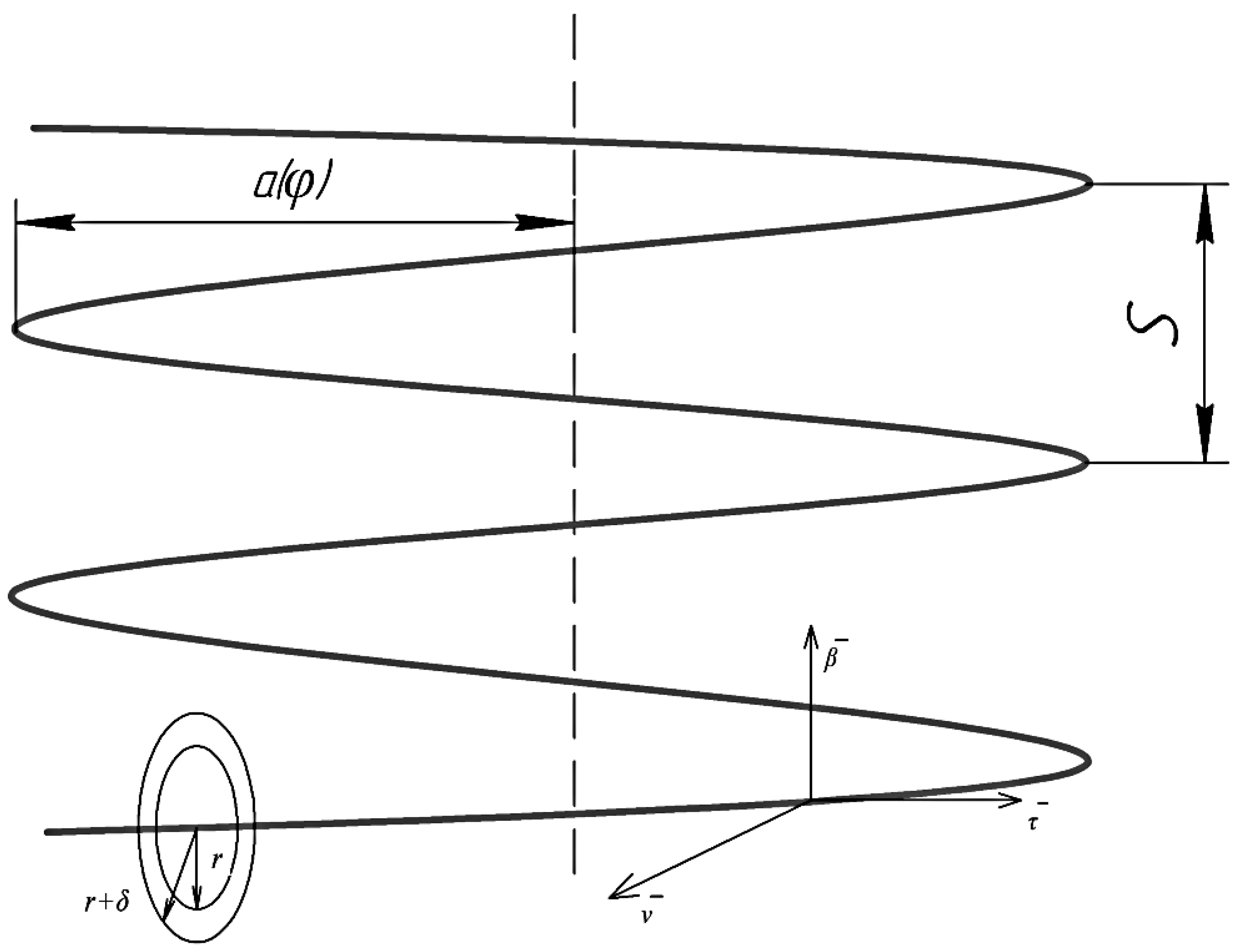
d is the pipe diameter (Figure 1).
When K > 1.35 the curvature of the pipe does not affect the nature of fluid movement. Therefore, R e K p = 13.5 D d . However, this is true for small d/D ratios [12].
When 3 R / d 200 , R = 0.5 D , the critical value of the Reynolds number is calculated as [12,13]:
R e к p = 1500 R d 0.3
Due to the turbulent flow in curved pipes and due to the twist of the flow due to secondary flows and mixing increases, the heat transfer coefficient is higher than in straight pipes. The transition from laminar flow to turbulent flow in coils is presented in [14,15]:
R e к p = 2 · 10 4 d D 0.32
According to the simulated coil, the parameters D and d are performed under boundary conditions, so that the curvature affects the flow regime of the fluid in the pipe, but it can be assumed that there is no transverse circulation in the flow, and the fluid movement is assumed to be axisymmetric.
It is assumed that the motion of an incompressible fluid has a stationary, isothermal, and turbulent character. The density, heat capacity, and thermal conductivity coefficient do not change during the movement of the coolant. Figure 2.
In order to use the geometric symmetry of the coil channels and assuming that the bending radius of the coil is much larger than the diameter of the channel, we use a special orthogonal coordinate system associated with an axial helix with a constant bending radius determined by the equation, taking into account the ratio of torsion to the curvature of the pipe [16]:
ρ φ = a φ e φ + K ρ k ,
In coordinate form, Equation (4) takes the following form:
x = a φ cos φ ; y = a φ sin φ ;       z = ζ K φ .
where ρ φ is the radius-vector of a point on the centerline;
e φ = i cos φ + j sin φ ; i ,   j ,   k –orts of the Cartesian coordinate system;
k is a unit vector directed along the z-axis;
φ is the helix parameter;
ζ is the entered parameter that takes into account the lifting angle of the coil. To simplify the solution, this parameter will not be taken into account in the future;
K = S 2 π , S is the screw channel pitch;
a φ is the bending radius of the helix axis (Figure 2).
The presented system of equations, unlike those considered, can be adapted for any type of coil with a helical movement of a coolant with a circular channel section. The model can be changed for heat exchangers as well as heating surfaces of the same boiler in question, which includes a ceiling coil, by taking into account the angle of rise equal to 0.
By determining the vectors of the accompanying reference point for a given axial line of the coil, and using them as basis vectors τ , β , γ , we obtain new variables b , φ , ψ , which are related to the variables of the Cartesian coordinate system x ,   y , z , ratios [17,18,19]:
x = a φ cos φ + b v x φ cos ψ + θ φ + β x φ sin ( ψ + θ φ ) , y = a φ sin φ + b v y φ φ   cos ψ + θ φ + β y φ sin ( ψ + θ φ ) z = K φ + b v z φ φ   cos ψ + θ φ + β z φ sin ( ψ + θ φ ) , ,
which in the case of a constant bending radius of the channel, a φ = a 0 , expressions are obtained for the vectors of the accompanying reference:
τ = a 0 g φ + K k a 0 2 + K 2
β = K g φ + a 0 k K 2 + a 0 2
v = e φ
κ φ = K K 2 + a 0 2 = c o n s t
where g φ = i sin φ = j cos φ ; and
κ φ is the torsion of the axial line of the channel.
For a given coordinate system b , φ , ψ , we have the following characteristics [20]:
(1) The Lyame coefficient (at a constant radius):
H φ = a 2 + K 2 · 1 a b a 2 + K 2 · cos ψ + θ
(2) Non-zero Christoffel symbols:
Γ φ φ φ = 1 H φ · H φ φ ,   Γ φ ψ φ = 1 H φ · H φ ψ
Γ φ b φ = Γ b φ φ = 1 H φ · H φ b ,   Γ ψ b ψ = Γ b ψ ψ = 1 b
Γ φ φ ψ = H φ b 2 · H φ ψ ,   Γ φ φ b = H φ · H φ b ,   Γ ψ ψ b = b
Thus, in the chosen system, the equation of motion, continuity, and transfer of the amount of energy is written as follows [21]:
ρ [ 1 H φ b · ( φ ( H φ b V φ V φ ) + ψ ( H φ 2 b V ψ V φ ) ) ] + ρ [ 1 H φ b ( b ( H φ 2 b V b V φ ) ) V φ V φ 1 H φ H φ φ ] = P φ + 1 H φ b ( φ ( H φ b T φ φ ) + ψ ( H φ 2 T φ φ ) ) + 1 H φ b ( b ( b H φ 2 T b φ ) ) T φ φ 1 H φ H φ φ
ρ [ 1 H φ b · ( φ ( b 2 V φ V ψ ) + ψ ( H φ b V ψ V ψ ) ) ] + ρ [ 1 H φ b ( b ( H φ b 2 V b V ψ ) ) V φ V φ 1 H φ H φ ψ ] = P ψ + 1 H φ b ( φ ( b 2 T φ ψ ) + ψ ( H φ b T ψ ψ ) ) + 1 H φ b ( b ( b 2 H φ T b ψ ) ) T φ φ 1 H φ H φ ψ
ρ [ 1 H φ b · ( φ ( b V φ V b ) + ψ ( H φ V ψ V b ) ) ] + ρ [ 1 H φ b ( b ( H φ b V b V b ) ) V φ V φ 1 H φ H φ b V ψ V ψ 1 b ] = P b + 1 H φ b φ b   T φ b + ψ H φ T ψ b + + 1 H φ b b b   H φ T b b T φ φ 1 H φ H φ b T φ φ 1 b
φ ρ V φ   b + ψ ρ V Ψ H φ + b ρ V b H φ b = 0
where T i j = 2 μ D i j , i = b , φ , ψ ; j = b , φ , ψ —physical components of the stress tensor deviator; μ is the viscosity, taking into account turbulence.
V i ,   i = b , φ , ψ —physical components of the velocity vector;
D i j = 1 2 V i j + V T i j ,
—physical components of the strain rate tensor; V is the velocity gradient tensor; and V T is the transposed velocity gradient tensor.
Direct numerical modeling was used as a turbulence model.

3. The Main Part

It is necessary to design, select equipment, install, and adjust the automatic control system of an educational laboratory stand, which repeats the operation of a direct-flow coil-type boiler in idle mode without heating the coolant. The main task is to pick up a device with built-in hardware and software. The device must be designed to control sequential logical processes in real time. The number of input variables plays an important role in the selection of the main equipment X1, X2…Xn: water pressure, engine speed, as well as possible connection of new parameters and, in accordance with the requirements of the process, possible changes in the state of the outputs Y1, Y2…Yn: hydraulic system pressure regulation, engine speed change, etc. When choosing equipment, it is also necessary to take into account the optimal price-performance ratio.

3.1. Experimental Setup

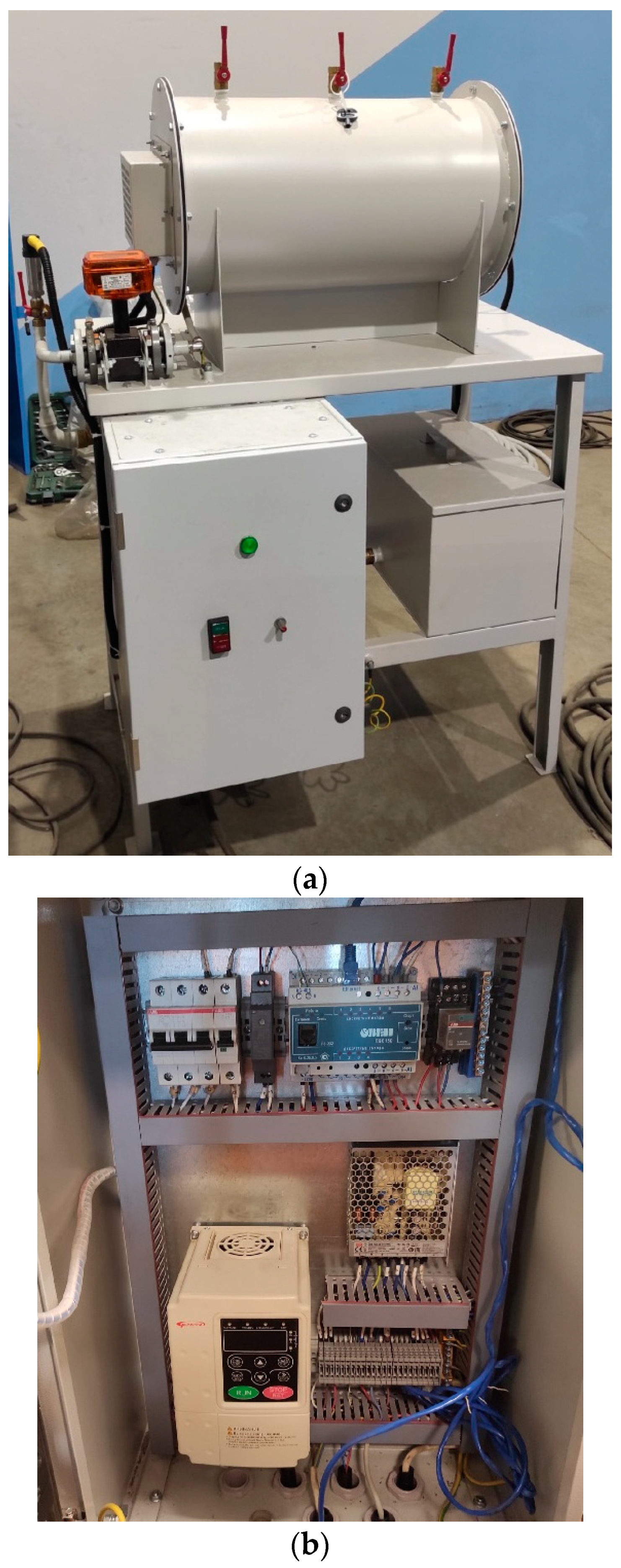
A common working area has been designed to accommodate the equipment—a metal table with attached brackets for a monoblock, pump, control cabinet, flow meter, and other auxiliary equipment. The laboratory stand has been assembled and adjusted (Figure 3).

3.2. Diagrams of the Hydraulic and Aerodynamic Systems of the Stand

A special laboratory workshop has been developed for the designed stand, which, in accordance with the tasks set, should cover the following sections of training [22]:
(1)
An investigation of liquid and air flow modes;
(2)
Pump and fan control;
(3)
Study of the operation of devices for measuring the speed of movement, volume, and temperature of air and liquid in systems.
Laboratory work No. 1, “Investigation of fluid flow modes in a wound coil”, includes the following parts of a monoblock (Figure 4): a wound coil, a container with feed water, a pump, a flow meter, control and measuring and shut-off valves, and a control cabinet.
The liquid (water) is fed into the wound coil by means of a pump from a filled feed water tank. The circuit is closed, the water returns to the tank. The measuring part of the stand allows you to record the parameters of the liquid flow through the scoreboard on the flow meter or with the subsequent output of indicators on the PC screen using software.
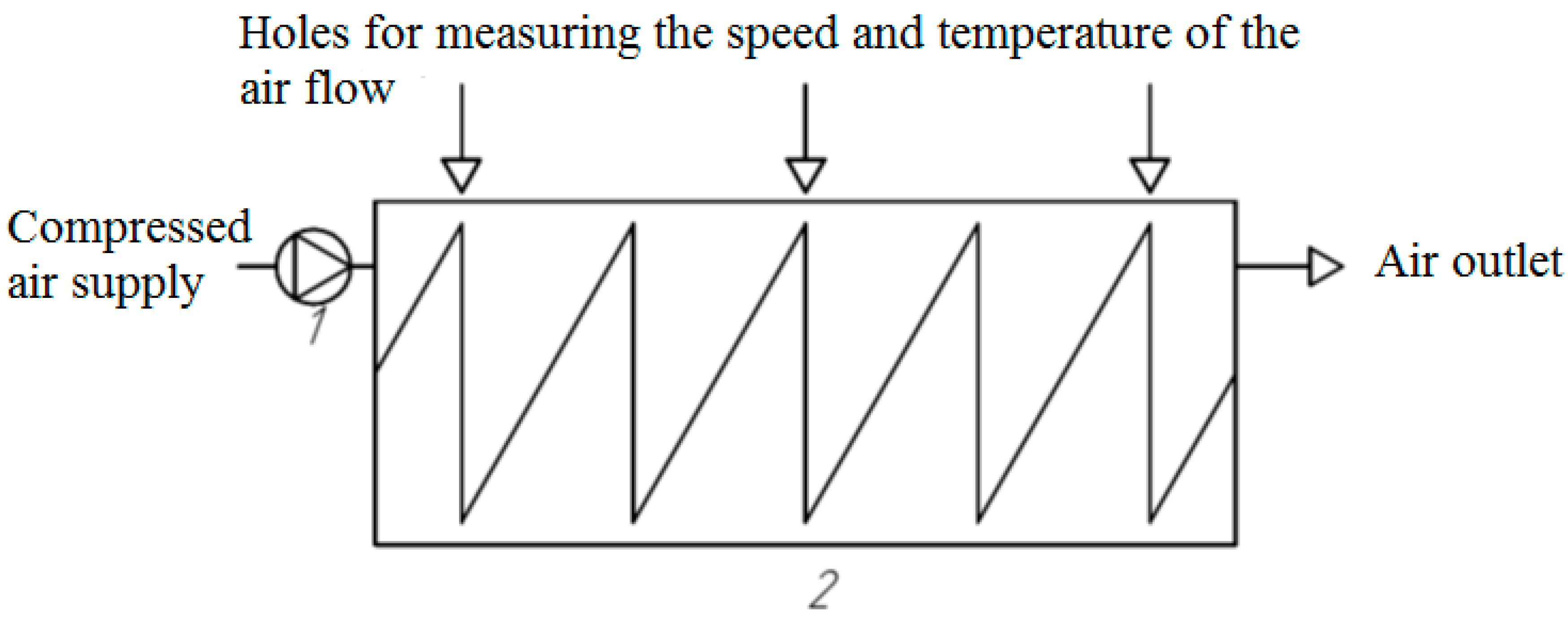
Laboratory work No. 2 “Investigation of gas (air) flow modes in a cylindrical coaxial channel” includes the following parts of a monoblock: a metal cylinder, a wound coil forming a coaxial channel, a fan, an anemometer, shut-off valves, and a control cabinet (Figure 5).
Compressed air is supplied through a channel in the cylinder cover. The air passes through the channel and exits from the other side of the cylinder through a similar hole in the second cylinder cover. The coaxial coil inside the cylinder creates aerodynamic drag, forming a vortex of airflow. The measuring part of the stand allows you to measure the parameters of the speed and temperature of the air flow using an anemometer by placing a telescopic probe in special holes in the cylinder along the movement of the air flow. The anemometer is controlled using a smartphone, followed by uploading summary tables with experimental values to a PC.
  • Stand Operation Algorithm
The pump motor speed is selected as an adjustable variable. The dependent variables are the speed and flow rate of the coolant and the pressure in the coil (1). An indicator of the safe operation of the hydraulic system is the pressure parameter (p, MPa) [23].
ω = f υ d t H = f ω d t Q = f ω d t
In accordance with the task, Figure 6 shows a block diagram of the operation of the laboratory stand on the hydraulic system.

3.3. Stand Management

The control of the laboratory stand is carried out by means of a control device—a controller. An open control is selected as an automatic control system (Figure 7). For ease of control and reading of signals in the system, the control device receives information about the control goal in the form of a time-varying task g(f) and forms a controlling influence on the object in such a way that the control goal is achieved x(t). Since the output value x is not measured, the actual state of the object is not monitored. The control algorithm linking the control action u(t) with a task g(f) is formed on the basis of a mathematical model of the object, which is known with high accuracy.
The advantages of the presented scheme are its ease of operation and the possibility of its further modernization, taking into account the new capabilities of the equipment [24]. The disadvantage is the condition that the object should not be affected by external disturbances, which is a difficult task [25]. The control device is a programmable logic controller of the ARIES brand with CoDeSys 2.3 (integrated development environment (IDE) of applications for programmable controllers). To measure the flow rate, an electromagnetic flow converter of the MasterFlow brand has been selected (Scientific and Production Association «Prompribor», Kaluga City, Russia). A Pedrollo Vortex surface pump was selected as a hydraulic device. Pressure sensors DDM-10 have been selected for pressure monitoring. To measure the air velocity, an anemometer smart probe from TESTO was purchased (Testo SE & Co. KGaA, Lenzkirch, Germany), which sends data to a smartphone, and full information can be downloaded to a PC. For automatic control of the rotation speed of alternating current electric motors, a device from the company MOMENTUM—frequency converter MT-100 has been selected.

3.4. The Practical Part

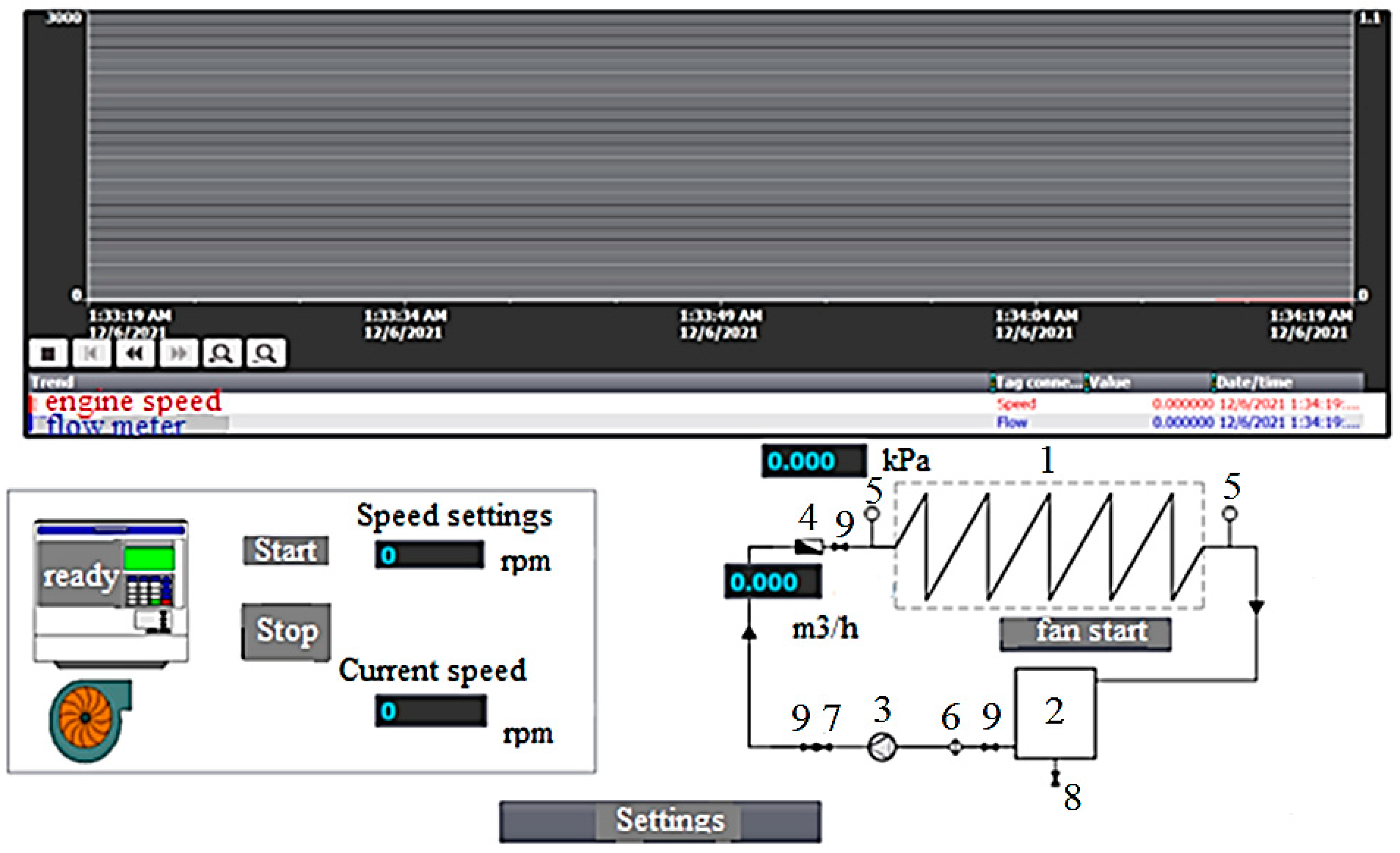
The hydraulic system of the stand was tested at different speeds of the pump motor. The regulation was carried out using a PC and a controller via the Vincc program (Figure 8).
The virtual control desktop assumes the start of the frequency converter (ready for operation), setting the speed of the electric motor (revolutions per minute). The current values on the virtual control change in real time, but with a delay of a couple of seconds [26]. The diagram shows a warning lamp about the pump switching on. The online values of the flow rate (cubic meters per hour) and the pressure at the inlet to the coil (kPa) are recorded. Recording and saving of experimental values is carried out in a journal in Excel format on a connected PC.

4. Results and Discussion

4.1. Experimental Results

The results of the first experiment (a sample without repeating values in terms of speed versus time) are presented in Table 1. The kinematic viscosity of liquid–water at a temperature of 5.6 °C during the experiment is equal to 1.519 × 10⁻⁶ m2/s.
At D/d = 25 (for the stand), based on Equation (3), the number ReKp = 7139.85, which is significantly more than for straight pipes, because it is associated with the stabilizing effect of the centrifugal force and the transverse circulation excited by it on the flow at the wall.
Based on the experimental values obtained, it can be concluded that the motion is turbulent, and the mathematical model requires adjustment for turbulence because, at the moment, it describes laminar motion in curved pipes to a greater extent.

4.2. Simulation Results

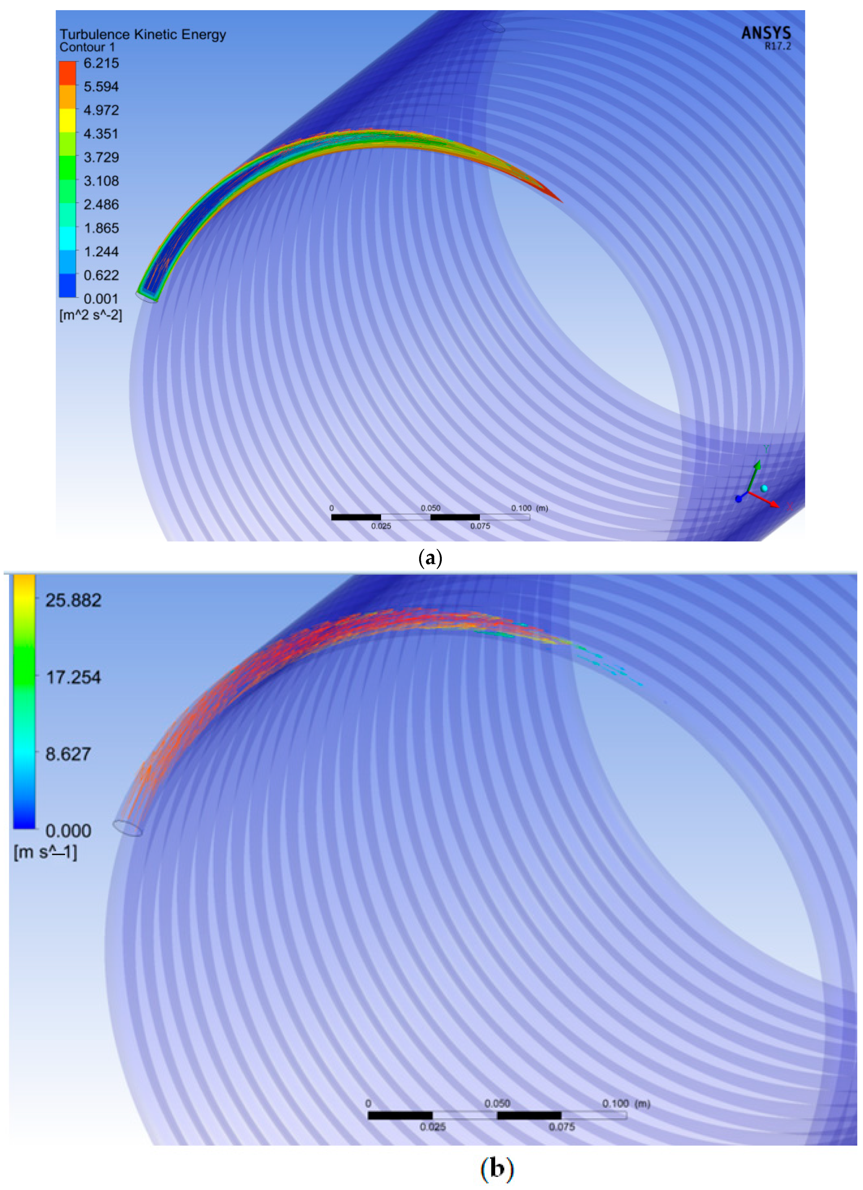
The developed mathematical model made it possible to simulate a complex hydrodynamic process of heat exchange in a coil with a constant bending radius of a screw pipe (Figure 9a,b).
According to the simulation results, it can be seen that for small values of the Dean number, the curvature of the pipe does not yet affect the nature of the movement of the coolant—the vectors indicate a parallel movement of the curved axis of the pipe, there is no transverse circulation in the flow, and the velocity distribution and the law of resistance in curved pipes turn out to be the same as in straight ones.
For a more accurate analysis by the Dean number and an assessment of the nature of the movement of the coolant through curved pipes, depending on the speed, it is necessary to simulate other scenarios that will allow you to see a more complete picture, close to the real processes in a direct-flow steam boiler of a coil type, and for comparison with the results of the experiment. It is possible to predict the movement of coolant in pipes with different bending radius, shape, and degree of contamination using new models, which will allow for future improvements to the system of chemical water purification for coils [27].

5. Conclusions

Within the framework of the presented work, the processes in a direct-flow steam boiler of the coil type were studied. The study is aimed at further improving the steam capacity and energy efficiency of the basic direct-flow boiler.
The presented mathematical model for boiler coils can be used as a universal one for other types of heat exchangers and coil heating surfaces in various steam units, since in the theoretical part, elements of any kind of curved coil are taken into account as corrections.
The designed educational laboratory stand can be used for scientific and educational purposes. Experimental and calculated data on the hydraulic system made it possible to identify a more accurate critical value of the Re number for a curved pipe of a given diameter, which can subsequently be applied to the boiler to regulate the nature of the movement of the coolant, as well as to the steam capacity and energy efficiency of the boiler through the speed of the engine. Additionally, the stand automation model can serve as a prototype for a fully automatic control system for a group of feed pumps in a boiler plant.
It is worth noting that in order to bring the laboratory stand closer to the boiler under study, it is necessary to improve it in the field of heating the coolant. Modernization of the stand will increase the level of accuracy of experimental data on the value of the Re number. Additionally, heating the water in the stand allows us to calculate and simulate approximate points in the coil by the phase change of the coolant, which in the future will simplify the regulation of the boiler, reduce fuel costs, and improve the efficiency of the installation.

Author Contributions

Conceptualization, S.K., K.O. and S.A.; Data curation, S.K., K.O. and S.A.; Formal analysis, S.K., K.O. and S.A.; Investigation, S.K. and K.O.; Methodology, S.K. and K.O.; Project administration, S.K. and K.O.; Supervision, S.K. and K.O.; Validation, S.K. and S.A.; Visualization, S.K., K.O. and S.A.; Writing—original draft, S.K. and K.O.; Writing—review & editing, S.K., K.O. and S.A. All authors have read and agreed to the published version of the manuscript.

Funding

This research received no external funding.

Data Availability Statement

Not applicable.

Conflicts of Interest

The authors declare no conflict of interest.

References

  1. Dudkin, M.M.; Osintsev, K.V.; Kuskarbekova, S.I. Experimental study of the operation of a coil-type steam boiler during opera-tion at the Northern oil field // Bulletin of the South Ural State University. Ser. Energy 2019, 19, 14–25. [Google Scholar] [CrossRef]
  2. Boje, E. Dry-out point estimation in once through boilers. In Proceedings of the 15th IFAC Symposium on System Identification, Saint-Malo, France, 6–8 July 2009; Volume 42, pp. 723–728. [Google Scholar] [CrossRef]
  3. Trojan, M. Modeling of a steam boiler operation using the boiler nonlinear mathematical model. Energy 2019, 175, 1194–1208. [Google Scholar] [CrossRef]
  4. Asotani, T.; Yamashita, T.; Tominaga, H.; Uesugi, Y.; Itaya, Y.; Mori, S. Prediction of ignition behavior in a tangentially fired pulverized coal boiler using CFD. Fuel 2008, 87, 482–490. [Google Scholar] [CrossRef]
  5. Mandø, M.; Rosendahl, L.; Yin, C.; Sørensen, H. Pulverized straw combustion in a low-NOx multifuel burner: Modeling the transition from coal to straw. Fuel 2010, 89, 3051–3062. [Google Scholar] [CrossRef]
  6. Bruce-Konuah, A.; Jones, R.V.; Fuertes, A.; de Wilde, P. Central heating settings in low energy social housing in the United Kingdom. Energy Procedia 2019, 158, 3399–3404. [Google Scholar] [CrossRef]
  7. Dixon, D.; Nguyen, A. An Empirical Oil, Steam, and Produced-Water Forecasting Model for Steam-Assisted Gravity Drainage with Linear Steam-Chamber Geometry. SPE Reserv. Eval. Eng. 2019, 22, 1615–1629. [Google Scholar] [CrossRef]
  8. Kusumastuti, I. Effects of Various Steam Flooding Injection Patterns and Steam Quality to Recovery Factor. J. Earth Energy Eng. 2019, 8, 33–39. [Google Scholar] [CrossRef] [Green Version]
  9. Suvorov, D.; Frantsuzova, G.; Hubka, L. Nonlinear process control once-through boiler. In Proceedings of the 2014 12th International Conference on Actual Problems of Electronics Instrument Engineering (APEIE), Novosibirsk, Russia, 2–4 October 2014; pp. 701–709. [Google Scholar] [CrossRef]
  10. Jha, R.S.; Lele, M.M. Dynamic modeling of a water tube boiler. Heat Transf. 2022, 51, 6087–6121. [Google Scholar] [CrossRef]
  11. Mojica-Cabeza, C.D.; García-Sánchez, C.E.; Silva-Rodríguez, R.; García-Sánchez, L. A review of the different boiler efficiency calculation and modeling methodologies. Inf. Técnico 2021, 86, 69–93. [Google Scholar] [CrossRef]
  12. Zykov, A.K. Steam and Hot Water Boilers: A Reference Manual, 2nd ed.; Library of the Heat Installer: Saint-Petersburg, Russia, 1995; p. 119. [Google Scholar]
  13. Petukhov, B.S. Heat Exchange and Resistance during Laminar Fluid Flow in Pipes; Energiya Publishing House: Moscow, Russia, 1967; p. 409. [Google Scholar]
  14. Germano, M. The Dean equations extended to a helical pipe flow. J. Fluid Mech. 1989, 203, 289–305. [Google Scholar] [CrossRef]
  15. Kirillov, P.L.; Yuryev, Y.S.; Bobkov, V.P. Handbook of Thermohydraulic Calculations; «Energoatomizdat» Publishing House: Moscow, Russia, 1984; p. 296. [Google Scholar]
  16. Mori, Y.; Nakama, N. Investigation of heat exchange during forced fluid flow in curved pipes. Int. J. Heat A Mass Transfer. 1965, 8, 61–82. [Google Scholar]
  17. Bagoutdinova, A.G.; Zolotonosov, Y.A.D. Coil Heat Exchangers and Their Mathematical Description; «Doe» Publishing House, 2015; Volume 1, pp. 44–45.
  18. EVachagina, K.; Bagoutdinova, A.G.; Zolotonosov, Y.D.; Knyazeva, I.A. The conjugate problem of heat exchange during the flow of liquids in coils with a changing bending radius of a helical spiral. Bull. Technol. Univ. 2015, 18–20. [Google Scholar]
  19. Nazmeev, Y.G. Hydrodynamics and Heat Exchange of Swirling Flows of Rheologically Complex Media; «Energoatomizdat» Publishing House: Moscow, Russia, 1996; p. 68. [Google Scholar]
  20. Aronov, I.Z. Heat Exchange and Hydraulic Resistance in Curved Pipes: Diss. Candidate of Technical Sciences; KPI: Kiev, Ukraine, 1950; p. 130. [Google Scholar]
  21. Zapryanov, Z.; Christov, C.; Toshev, E. Fully developed laminar flow and heat transfer in curved tubes. Int. J. Heat Mass Transf. 1980, 23, 873–880. [Google Scholar] [CrossRef]
  22. Bagoutdinova, A.G.; Zolotonosov, Y.D. Mathematical model of the conjugate heat transfer problem in turbulent flow in channels of complex geometry. Izv. KGASU 2013, 2, 157–167. [Google Scholar]
  23. Bulkin, A.E. Automatic Regulation of Power Plants: A Textbook; MEI: Moscow, Russia, 2016; p. 508. [Google Scholar]
  24. Dudkin, M.M.; Osintsev, K.V.; Kuskarbekova, S.I. Development of methodological foundations for the study of vaporization processes during the movement of a multicomponent liquid in direct-flow coil-type boilers by mathematical modeling methods. Ind. Power Eng. 2020, 11, 16–24. [Google Scholar] [CrossRef]
  25. Mura, L.; Buleca, J.; Zelenakova, L.; Qineti, A.; Kozelova, D. An analysis of selected aspects of international business in Slovak dairies in the EU framework. Mljekarstvo Časopis Za Unaprjeđenje Proizv. I Prerade Mlijeka 2012, 62, 219–226. [Google Scholar]
  26. Buleca, J.; Mura, L. Quantification of the Efficiency of Public Administration by Data Envelopment Analysis. Procedia Econ. Finance 2014, 15, 162–168. [Google Scholar] [CrossRef]
  27. Andrejovska, A.; Buleca, J.; Drab, R. Impact of Macroeconomic Factors on Corporate Income Tax in the V4 Countries Using Regression Analysis. In Proceedings of the Central European Conference in Finance and Economics (CEFE2015), Herľany, Slovak Republic, 30 September–1 October 2015; pp. 1–9. [Google Scholar]
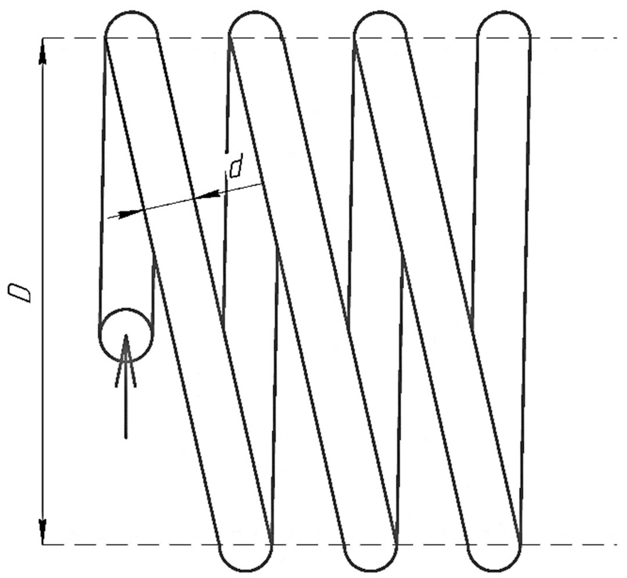
Figure 1. Coil diagram.
Energies 15 08203 g001
Figure 2. Coordinate system: S—step, a φ —curving radius, r—radius of the pipe, δ—thickness of the pipe.
Energies 15 08203 g002
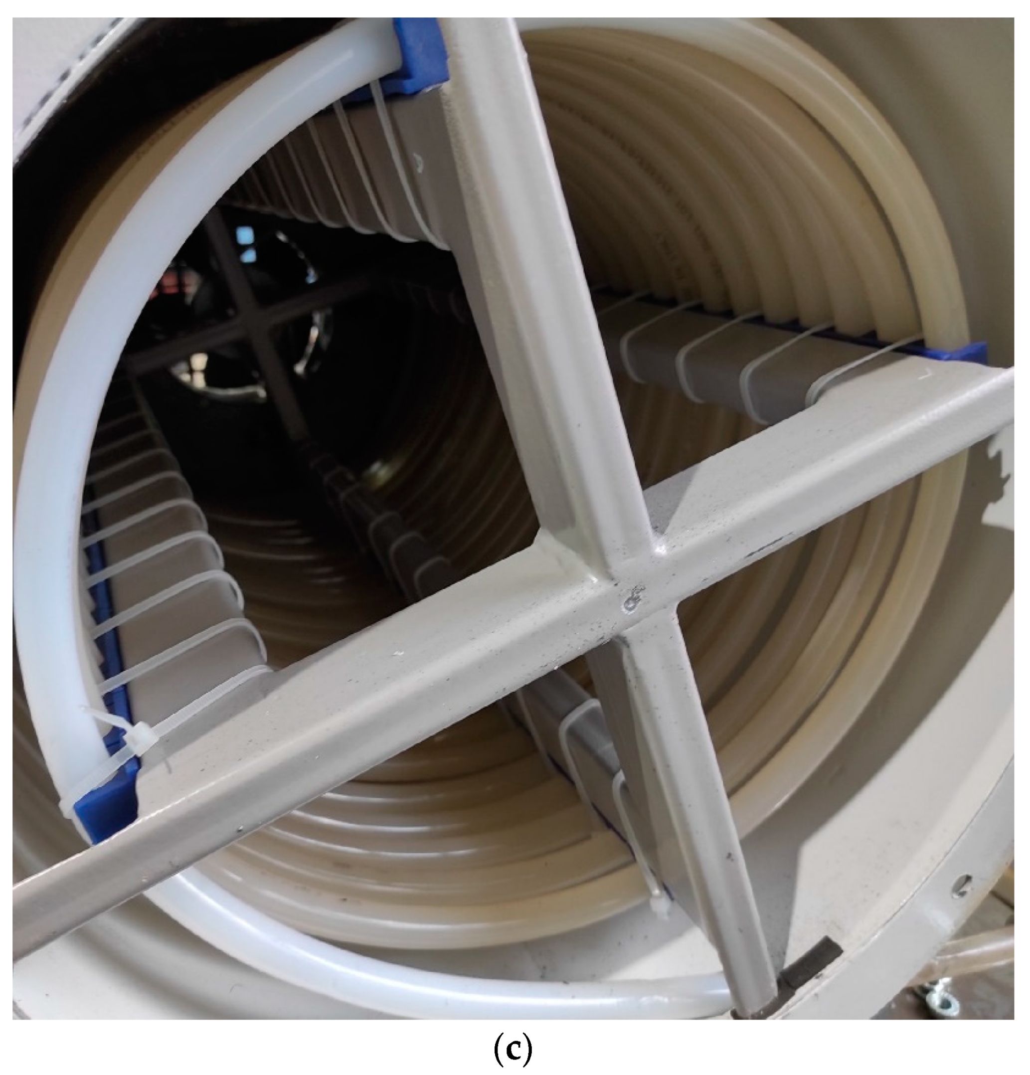
Figure 3. Photo of the laboratory stand; (a) laboratory stand (general view); (b) photo of the control cabinet; and (c) wound coils of the stand.
Energies 15 08203 g003aEnergies 15 08203 g003b
Figure 4. Diagram of the hydraulic system of the laboratory stand: 1—coil; 2—feed water tank; 3—pump; 4—flow meter; 5—pressure sensor; 6—sump filter; 7—check valve; 8—drain ball valve; and 9—ball valve.
Energies 15 08203 g004
Figure 5. Diagram of the aerodynamic system of the laboratory stand: 1—fan; and 2—cylinder with a coil.
Energies 15 08203 g005
Figure 6. Flowchart of the algorithm for the operation of the laboratory stand on the hydraulic system.
Energies 15 08203 g006
Figure 7. Functional diagram of the automatic control system: yy—control device; and O—control object.
Energies 15 08203 g007
Figure 8. Virtual control desk of the laboratory stand (where 1—coil (pipe); 2—water tank; 3—pump; 4—flow meter; 5—pressure sensor; 6—sump filter; 7—check valve; 8—drain ball valve; and 9—ball valve).
Energies 15 08203 g008
Figure 9. The results of modeling the hydraulic process in a coil for a laboratory stand: (a) kinetic energy and (b) velocity vectors of the coolant.
Energies 15 08203 g009
Table 1. Results of the experiment.
Engine Speed, rpmPressure, kPaConsumption, m3/hNumber Re
2500.38531.070.902310,119.5
2354.8493.9660.88292,063.4
2002.16331.8340.775248,325.8
1885175.0570.7233,794.6
1531.2175.0570.623189,913.2
1296.8872.8170.623160,850.7
999.9271.8880.52124,019.0
881.671.8880.314109,343.9
764.4454.7380.31494,812.7
619.4454.1290.31376,828.5
592.7654.1280.26273,519.4
499.9628.6090.26262,009.5
269.126.9690.04733,378.7
151.963.3630.02418,847.4
Publisher’s Note: MDPI stays neutral with regard to jurisdictional claims in published maps and institutional affiliations.