Article

Flexible Power Point Tracking Using a Neural Network for Power Reserve Control in a Grid-Connected PV System

by
Jishu Mary Gomez
and
Prabhakar Karthikeyan Shanmugam
*
School of Electrical Engineering, Vellore Institute of Technology, Vellore 632014, Tamil Nadu, India
*
Author to whom correspondence should be addressed.
Energies 2022, 15(21), 8234; https://doi.org/10.3390/en15218234
Submission received: 6 October 2022 / Revised: 28 October 2022 / Accepted: 31 October 2022 / Published: 4 November 2022
(This article belongs to the Special Issue Control and Optimization of Electrical Power and Energy Systems)

Abstract

:
Renewable energy penetration in the global energy sector is in a state of steady growth. A major criterion imposed by the regulatory boards in the wake of electronic-driven power systems is frequency regulation capability. As more rooftop PV systems are under installation, the inertia response of the power utility system is descending. The PV systems are not equipped inherently with inertial or governor control for unseen frequency deviation scenarios. In the proposed method, inertial and droop frequency control is implemented by creating the necessary power reserve by the derated operation of the PV system. While, traditionally, PV systems operate in normal MPPT mode, a derated PV system follows a flexible power point tracking (FPPT) algorithm for creating virtual energy storage. The point of operation for the FPPT of the PV is determined by using a neural network block set available in MATLAB. For the verification of the controller, it is applied to a PV array in a modified IEEE-13 bus system modeled in the MATLAB/Simulink platform. The simulation results prove that when the proposed control is applied to the test network with renewable energy penetration, there is an improved system inertia response.

1. Introduction

Renewable energy systems (RESs) are alternate sources of energy that are forming an integral part of the modern utility system with their increasing penetration levels. The operation of these systems is meticulously scrutinized for possible causes of instability conditions. This initiates the exploration of simple and robust control techniques that equip the RES with a proactive operation. The control techniques are deployed to control system parameters and safeguard the power system’s stability.
The inertia in a body of mass helps it to maintain its state of being; this is one of the important system parameters that hold the key to synchronized system operation. The inertia in the rotary synchronous generators inherently responds to frequency changes that are a consequence of power imbalances in the network [1]. The RES is an inverter-interfaced system that decouples any rotational energy that may be present, causing a reduction in system inertia and invisibility to system frequency dynamics. Unprecedented changes in generation or load require fast frequency recovery measures or inertia response. An absence of inertia leads to violations of the statutory limits of the rate of change of frequency (ROCOF) and defined frequency nadir [2]. To counteract the fast frequency variations, inverters in the RES are controlled to dispatch power into the network based on the measurement of frequency and its derivatives. The classic PID control inverters accompanied by energy storage systems have evolved to predictive control based on the system operative [3].
As a solution, the inertia response is synthesized and called the virtual inertia control. It is implemented to operate for short periods (1–5 s) through topologies that help integrate and control the active power output of the RES into the grid [4]. The design of the control system is defined by the necessary system inertia requirement, speed of response, frequency recovery response, active power response, and response to both rising and falling frequencies [5].
Among various RESs, the most popularly installed photovoltaic systems have neither a rotary segment nor in-built energy storage that could induce an inertia response. The effect of reduced inertia on future power systems is a smaller energy buffer, larger frequency deviations, and a high differential change in frequency [6]. However, a virtual inertia-controlled PV system operates with the ability to reduce the frequency and active power oscillations during disturbances and aids in distributed energy storage system control [7]. The result of the investigations conducted in [8] indicates that during major imbalances in the system, the frequency response remains unaffected when the PV penetration is below 20%, while a penetration level greater than 50% could threaten system security. The modern power system is made of hybrid energy components where the DFIG and PV generator systems are the main contributors. In [9], a comparison of inertia control applied to PV and wind systems was made. The study shows that the controller time constant is smaller for PV systems when compared to wind systems. This implies that induced inertia in PV systems is more fast-acting than the control applied to wind systems. The output of RES generators is affected by moving clouds and has global and local implications. This affects the spinning reserve in the system, hence constant energy storage schemes are a necessity for inertia response in RESs [10]. Energy storage systems (ESSs) are used for up/down frequency regulation in virtual inertia control by injecting/absorbing active power. Some of the currently useful ESSs for frequency regulation systems are the Battery Energy Storage System (BESS), Flywheel ESS (FESS), Supercapacitor ESS (SCESS), and Superconducting Magnetic ESS (SCMESS). Additionally, a hybrid ESS may be used, which is a feasible combination of one or more of the aforementioned ESSs [11].
Virtual storage for inertial response can be created within the PV system without an ESS by operating it away from maximum power point tracking (MPPT). This is the derated/de-loaded operation of PVs [12]. In far sight, operating below maximum capacity may seem like a loss of energy and revenue. However, the cost–benefit analysis of de-loaded PVs against the normal MPPT-operated PV system made in [13] suggests a contradiction. The tariff for providing ancillary frequency regulation service is double the energy price in the US and European networks. This compensates for the losses incurred as a consequence of PV operation below the MPP. Therefore, offering a regulation-up operation can create revenue benefits for private PV operators and improve inertia response for the utility system. A cost comparison of energy storage systems versus de-loaded operation in [14] also suggests that curtailing PV power is more beneficial. If a PV system of 1 MW provides 0.8 MW of reserve, then the cost is compared with a battery with a capacity of 0.8 MW. The cost–benefit reduces with the decrease in the size of the battery, i.e., for battery capacities higher than 1 MW, reserving PV power is more advantageous. As PV generator implementation is fast increasing, research attempts are made to optimally control the extraction of power from the source and the injection into the grid to obtain an inertia response similar to the traditional synchronous generator action.

Contribution

This work is a continuation of the research investigating the inertia response of renewable-energy-penetrated systems. In this regard, the various frequency control capabilities in RESs were studied [15]. Furthermore, a study of the frequency response of a standard test system with changes in system load and renewable energy penetration proved that frequency control is a necessity in RESs to induce inertia response during generation–load imbalance scenarios [16]. The reduction in inertia response with an increase in renewable energy penetration is inevitable, owing to the fact that the power electronic connection of the RES to the grid is inevitable. Therefore, a two-level inverter system is necessary for frequency control in RESs to obtain optimum power extraction from the source and controlled active power transmission to the grid [17].
In this paper, the power output of PV systems is kept flexible and not rigid to create a power reserve without an external ESS. PV systems normally operate at their maximum rated power; however, when the power output is varied below MPP, it operates at flexible power points, and this is called the derated mode of operation. The method helps create an energy buffer that can be charged or discharged according to system inertia requirements. Frequency control through the derated operation implemented in [14,18,19], and the control proposed in this paper, is based on the basic equation
P d e r = P M P P T P
where Pder is the derated power, PMPPT is the maximum power of the PV array, and ∆P is the power reserve necessary for frequency control. There are two power reserve modes of operation: (i) Mode 1: ∆P is fixed and (ii) Mode 2: ∆P varies with a change in frequency (∆f). The PV array in [14] operates under both modes of operation, in [19] the ∆P is fixed, and in [18] the power reserve operates in Mode 2 alone. In [14], to obtain the derated power control, the operating voltage of the PV was calculated considering several parameters: the MPPT voltage, the deload voltage corresponding to the change in frequency, and the voltage considering the available reserve in the respective PV system. The operating voltage estimation in [18] is based on the necessary power reserve calculated through the frequency controller. However, the maximum power estimation involves complex calculations using the short circuit current of the PV array. Several parameter estimations lead to errors in the final output. In the proposed control, the maximum power available in the PV array is obtained through direct relation using irradiance (G) and temperature (T) measurements. The G and T values used in the training of the neural network are randomly generated and are not associated with any location. The objectives of this paper are:
(i)
To achieve flexible power point tracking (FPPT) in a PV array using neural network training. Thus, the inputs to the PV array are simply G, T, and ∆P without complex calculated values, as used in [14,18].
(ii)
To operate the PV array on the left side of MPP as against the right-sided operation in [14,18]. The advantages and disadvantages of the operational characteristics on both sides of MPP are explained in Section 3.1.2.
In the next section, a summary of previous works using power reserve control is discussed. The frequency controller, FPPT characteristics, and implemented power reserve control, along with corresponding flowcharts, are elaborated on in the sub-sections of Section 3. The simulation results of the test system and proposed controller modeled and implemented in MATLAB/Simulink are explained in Section 4. The conclusions are stated in Section 5.

2. Literature Review

Appropriate power reserve control in PV systems requires the determination of (i) the maximum available power in the PV array and (ii) the amount of power reserve necessary to maintain system stability.
An accurate estimation of the power available in the system is necessary to create an optimum reserve for the inertia response capacity. The maximum power available in a PV system can be estimated in real time by measuring the irradiance and PV cell temperature [20]. The estimation of available active power without the use of temperature and irradiance sensor measurements may be obtained by applying curve-fitting techniques to the PV array parameters, as proposed in [21]. Neural network systems can be used to predict day-ahead power generation by training the network using previous two-day weather information [22]. In [23], the method suggests a combined estimation principle using a neural network with temperature and irradiance measurements.
The power reserve estimation concerning inertia is related to how much active power injection would be necessary for the corresponding frequency deviation. When there is a load imbalance, PL, in a network with only traditional generators, the frequency nadir is limited to fnadir-trad. If the same network is modified to replace the traditional synchronous machines with solar generation, then the frequency nadir is reduced to fnadir-RES < fnadir-trad. A careful analysis helps estimate the power reserve necessary to maintain the frequency response, as in the case of a conventional network for the same load disturbance, PL, i.e., to achieve fnadir-RES = fnadir-trad. For the proposed estimation, in [24], a parabolic approximation of the system frequency response was first made. Further, based on this approximation, the power reserves necessary for different PV penetration levels were calculated for a specified load change, PL. It is seen that as the frequency nadir decreases, the amount of reserve power necessary also increases. For the particular system under study, when there is a system inertia reduction of 20%, at an imbalance of 0.05 pu, the required active power is limited to 3% of rated power.
In a network consisting of several PV systems with different ratings, the individual contributions to power reserve are not equal. The deload in each of the PV systems is different, and therefore, the extraction of power must be controlled, i.e., the PV array with a higher deload percentage can provide more reserve while a lower deload percentage means a smaller reserve contribution [25]. However, large-scale power system network areas with high demand require higher power reserves. The virtual multi-slack droop control implemented in [26] selects the proper power reserve from RESs in different regions of a real Korean power system. A virtual slack bus along with the actual slack bus functions to compensate for any imbalance of load. Each RES is required to maintain a power reserve based on a power sensitivity analysis. Synchronized power control inverters used alongside MPPT inverters also provide frequency regulation while maintaining the DC voltage within safety limits [27]. The frequency overshoot, undershoot, and response time can be further reduced by applying optimization techniques to the inverter control parameters [28].

3. Control Technique

From the above discussions, the two main factors that are necessary for the appropriate control of derated PVs are (i) the power reserve necessary for frequency regulation and (ii) the point of operation of the PVs. In the literature summary, it is seen that neural networks have been used for the determination of maximum available power. However, not much work has been conducted in the area of flexible power point tracking. In the proposed control, the NN block gives the operating voltage point of the PV array. The NN is trained using irradiance, temperature, and the necessary power reserve estimate. The block diagram of the PV system with the proposed virtual inertia control is given in Figure 1. In the figure, the PV system is a two-level inverter and the output from the PV system is controlled through the boost converter. The PWM for the boost converter comes from the virtual inertia power reserve control. The PWM signal is generated by optimizing the voltage signal using a PI controller. The voltage from the NN block is compared with the PV voltage and then given to the PI controller, which is tuned in the block to obtain the corresponding duty ratio. The duty ratio is given to the PWM generator to generate the gate pulses. The DC voltage available at the capacitor is monitored at the inverter control, along with the system parameters, and generates pulses for the grid-side inverter. The output from the inverter control block is given to the frequency regulation system to generate a corresponding power reserve for any system frequency deviation. The power reserve estimate is utilized to control the PV output voltage at the virtual inertia block. The mathematical equations and the control algorithms used in the neural network block and the frequency regulation are discussed in this section.

3.1. Mathematical Formulation

3.1.1. Power Reserve for Frequency Regulation

Power reserve and inertia response are prerequisites for minimizing frequency deviations and a tolerance of ±0.2 Hz from nominal frequency is fixed to avoid system instability, generation loss, and load shedding, as defined in the network [29]. In traditional synchronous machines, the rotary motion generates the inertia response necessary to balance a change in load demand. The change in power to equalize the imbalance is:
P = P m P e = 2 H f d f d t
The same is conceptualized as virtual inertia in PV systems that do not have inherent inertia response, as:
P v i = 2 H v i d f d t = k i d f d t
Additionally, traditional generators use governors to control the power whenever there is a change in frequency. This change in power due to rotor governor action is emulated in the PV system as droop control and is defined as:
P d = 1 R f = k d f
An initial power reserve of P 0 is pre-set, and the droop coefficient, k d , becomes:
k d = P 0 f = P 0 f m a x / f 0
Thus, the required power reserve will be:
P = P 0 + P v i + P d = P 0 + k i d f d t + k d f
Power reserve control functions to reduce power output from the PV array at the frequency upper tolerance limit and provide maximum available power output when the frequency falls to the lower limit. The frequency controller output generates the necessary power reserve as shown in Figure 2.

3.1.2. Point of Operation of PV Array

PV systems are controlled to operate close to MPP, using conventional hill climbing techniques such as the Perturb and Observation (P&O) method and the Incremental Conductance (INC) method. Both P&O and INC methods work on the relation of derivative power with voltage and have almost similar tracking efficiencies. However, the INC method ignores the second-order term in the discrete differential equation of power and can rightly be termed an implementation of the P&O algorithm [30]. Similarly, a specific implementation of the INC method is proposed in [31], where a digital filter is used along with the INC algorithm to change the duty cycle and adjust the operation to achieve MPP. Although MPP operation is mandatory in most of the grid codes to achieve maximum yield from solar PV systems, the injection of a large amount of intermittent power leads to network overloading when there is a peak in the generation. Thus, a power reserve can be created and used as a cheap alternative to energy buffers such as battery storage systems and capacitors. The power reserve mode of operation is essentially a system performance-enhancing strategy that can be implemented on the DC–DC side and DC–AC side. The power reserve can be achieved through power, current, and P&O algorithm control. In the proposed control, the power reserve is created by controlling the PV array output at the DC–DC or the boost converter side. The control can be achieved through power control, current limit control, and P&O power reserve control [32]. The control proposed in [33,34] implements a closed-loop power control with fast dynamics and good steady-state responses. The current control techniques discussed in [35,36] describe the method as the simplest of all three methods. However, both methods can cause system instability during fast changes in irradiance levels. The P&O algorithm power reserve control is a robust method when system stability is the main criterion [37].
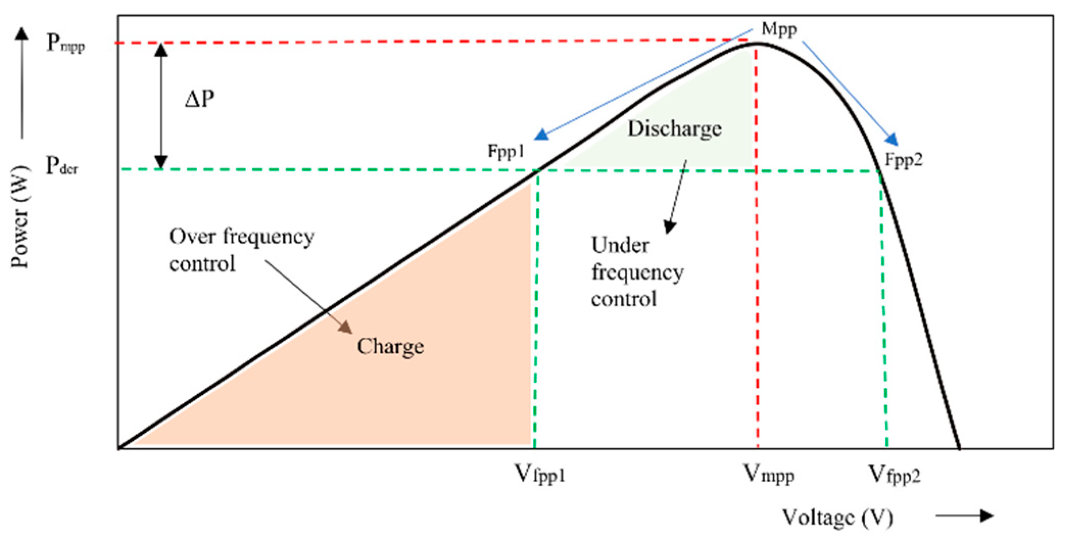
When PVs operate away from the fixed MPP, then the PVs are in the flexible PPT mode, and there are two possible operative points for the PV array—Fpp1 at the left and Fpp2 at the right of MPP in the PV curve, as shown in Figure 3. Operating the PV system on the left side has the advantage of preventing the operating voltage from reaching the open circuit voltage and will give stable operation even during high irradiance drops. On the right-hand side, there is a wider power reserve area, faster response, and higher converter efficiency [38].
For power reserve control using the P&O algorithm, the set of equations in (7) and (8) may be used for right-hand side and left-hand side operation, respectively:
v f p p * =     v M P P T ,     P d e r a t e d P M P P v p v 2 + v s t e p ,     P d e r a t e d > P M P P
v f p p * =     v M P P T ,     P d e r a t e d P M P P v p v 2 v s t e p ,     P d e r a t e d > P M P P
where v s t e p   is the perturbation step size used in the power reserve algorithm, v M P P T is the voltage for maximum power operation, and v f p p is the regulated voltage output from the derated PV. The step size, vstep, in Equations (6) and (7), power reserve, and PV power output to the grid are also fixed. In order to enable frequency regulation using power reserve control, the step size is varied according to frequency deviation. The control algorithm is implemented using a neural network and is discussed in Section 3.2.

3.2. Neural Network-Based FPPT

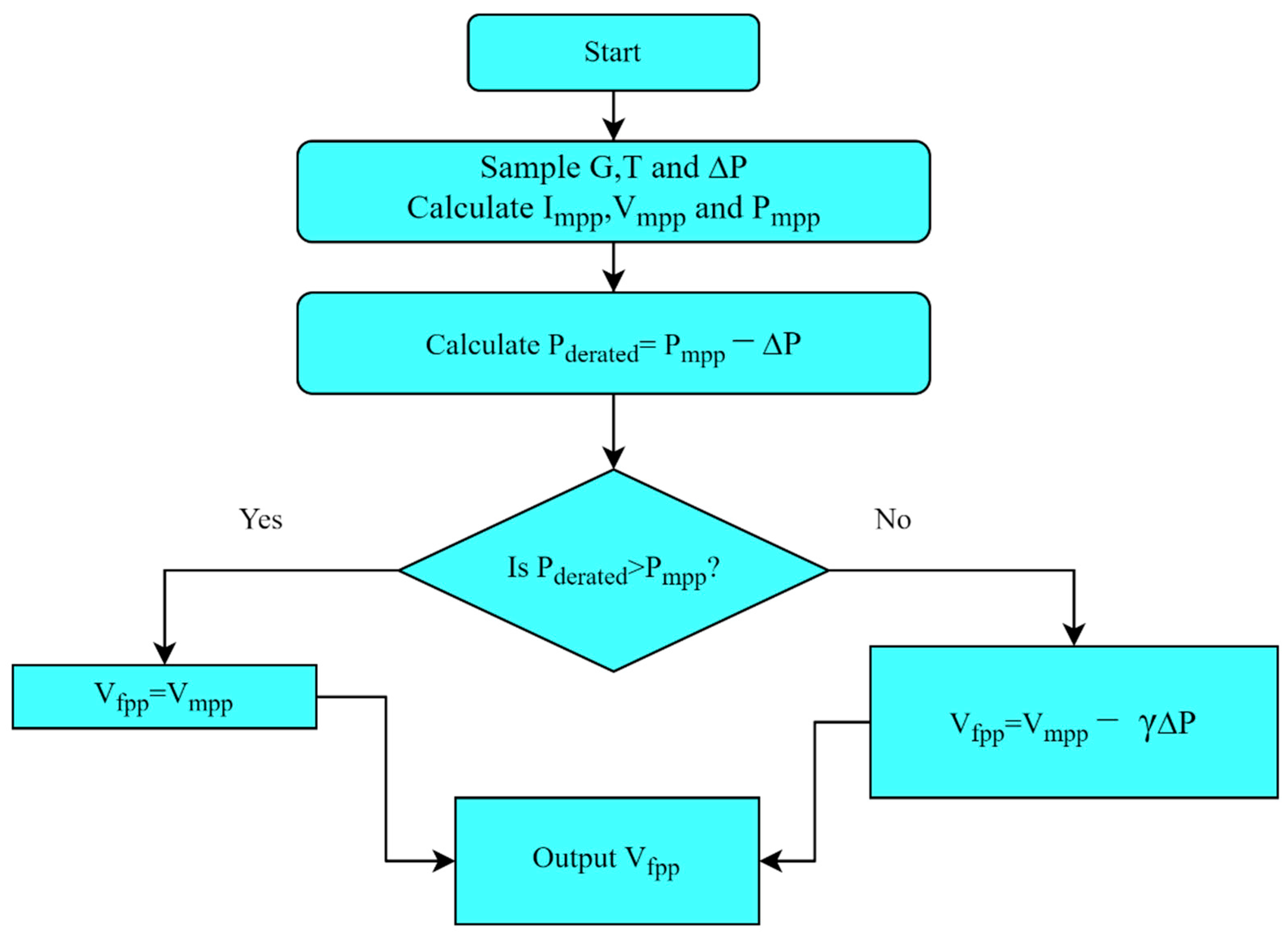
The proposed method for power reserve through flexible power point tracking is using the neural network. The flowchart for tracking the flexible power point is given in Figure 4. The maximum power available in the PV array is calculated by measuring the irradiance (G) and the temperature (T). The point of operation of the PV array depends on the required reserve power ∆P, which is obtained from the frequency regulation control block. The derated power output of the PV system is maximum power minus the necessary reserve. In the proposed control, the solar PV array is operated on the left side of the MPP. If derated power exceeds the MPP, the operating point will be limited at the MPP, and operation on the right side of the PV characteristic is eliminated.
The neural network NN-FPPT control is implemented in the MATLAB Simulink platform using the neural network block set.
Step 1: Define the problem: The inputs/predictors and the outputs/responses are arranged as matrices. In this case, the predictors’ matrix is a [1000 × 3] double matrix and the response matrix is a [1000 × 1] double matrix. The inputs are irradiance G, temperature T, and the required power reserve ∆P. The output is the operating voltage, Vfpp, of the PV array.
Step 2: Select data: The data are imported into the block for training. The data set in this case is a randomly generated set of 1000 values for inputs and output. The network is trained with a data set of inputs irradiance G, temperature T, the estimated power reserve ∆P, and the operating voltage of PVs Vfpp as output. The data are split for training, validation, and test sets into 70%, 15%, and 15% portions, respectively.
Step 3: Create network: The network is created with two functions, the sigmoid function in the hidden layer and the linear function in the outer layer. There are three inputs, using which the network plot is updated by the input data. The size of the hidden layer defines the number of neurons and is, by default, 10. The architecture of the neural network is a two-layered feedforward network, as shown in Figure 5.
Step 4: Train the network: The neural net fitting application in MATLAB/Simulink has three training algorithms, out of which, the Levenberg–Marquardt (LM) optimization is used to update the weight and bias values in the neural network. The LM training algorithm is used as it is the fastest among the three, although it requires more memory than other techniques. It uses the ‘trainlm’ function in the application. The Jacobian jX of performance specified by perf with respect to the weight and bias variables X is calculated using the backpropagation method. The variables are adjusted according to Levenberg-Marquardt:
  j j = j X j X
j e = j X E
d X = j j + I m u / j e
In the above equations, jj is the Jacobian matrix that contains the first derivatives of the network errors with respect to the weights and biases, je is the Jacobian of the vector of network errors, E is all errors in the network, and I is the identity matrix. The factor mu is the adaptive value that is increased in increments as mu_inc until the change results in a reduced performance value. The system is trained until one of the following conditions is fulfilled:
  • The specified number of repetitions/epochs have been completed.
  • The time limit has been reached.
  • The performance is minimized to the set goal
  • The performance gradient falls below the minimum of min_grad.
  • The value of mu exceeds its specified maximum value of mu_max.
  • The performance of the validation process increases to more than the maximum number of max_fail times.
Step 5: Analyze results: The data are analyzed by generating plots. The regression plot displays the network prediction corresponding to the responses for training, validation, and testing. From Figure 6, it is seen that the data fall perfectly in line with the 45-degree line, proving that the network outputs are equal to the responses. In case of not obtaining a perfect fit the first time, the network can be retrained with different weights and biases until an improved network is produced.
Step 6: The network is exported as a Simulink model for application to PV array control. The working of the designed NN block set is tested with a 250 W PV array. The obtained operating voltage is used to generate the PWM for the boost converter, as shown in the control diagram in Figure 1. The output of the case studies shows that the controller is well-trained.
Case 1: Reserve ratio is varied while the irradiance and temperature are kept constant.
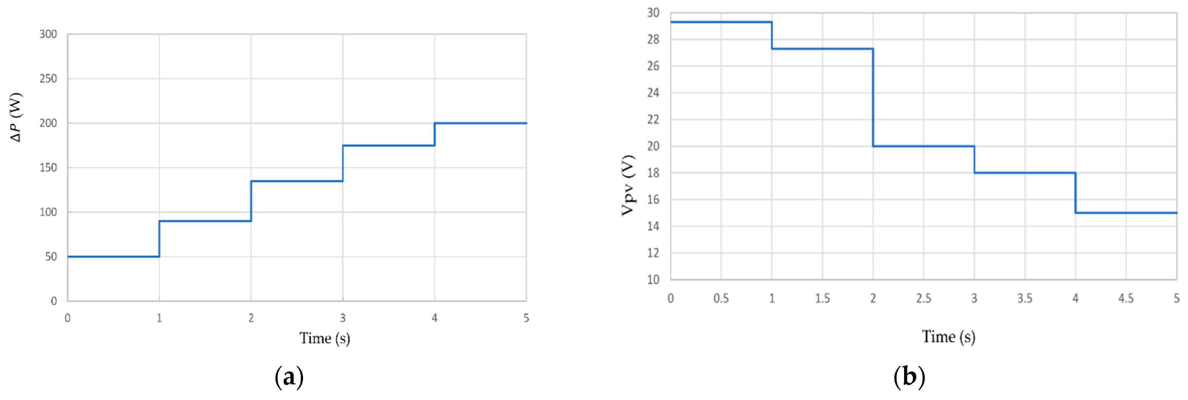
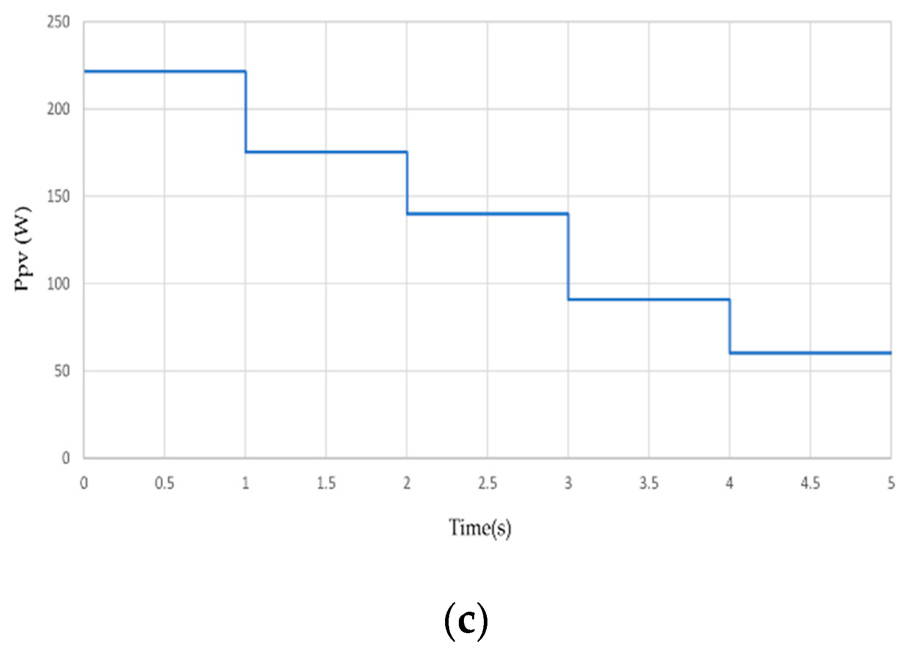
For the first case study, the G is fixed at 1000 W/m2, T at 25 °C, while ∆P is varied from 50 W to 200 W. From the system output waveforms shown in Figure 7a–c, it is seen that with an increase in ∆P, the output voltage and power of PV are derated.
Case 2: Reserve ratio is kept constant at 50 W and irradiance is varied.
The irradiance is varied in steps from 200 W/m2 to 1000 W/m2, as in Figure 8a, and the maximum available power in the system reduces. As shown in Figure 8c, the power output from the PV array reduces. However, as ∆P remains constant, the PV operating voltage in Figure 8b remains almost constant.
Case 3: Irradiance and power reserve ratio are both varied.
When the irradiance and power reserve ratio are both varied randomly, as shown in Figure 9a,b, respectively, it can be seen from Figure 9c that the PV operating voltage varies according to changes in the power reserve ratio, while the derated power output in Figure 9d varies according to irradiance and ∆P.

4. Simulation Results

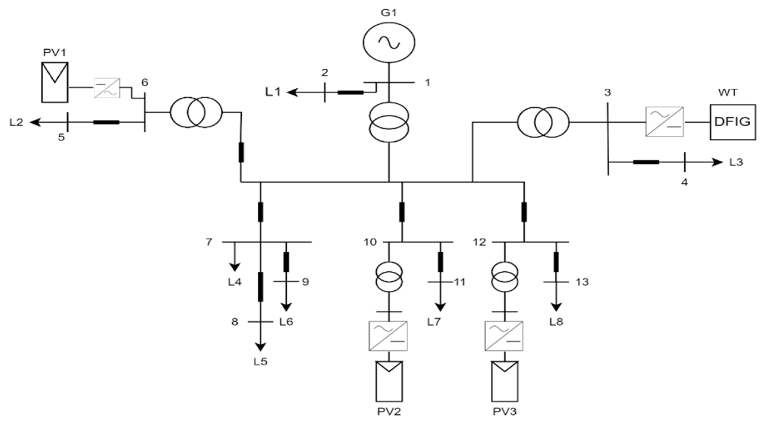
In the previous section, the NN-FPPT operation with a single 250 W PV array was verified. In this section, the NN-FPPT block is implemented in the test system. The test system is a modified IEEE-13 bus test system. The test system has five power sources and eight loads, as seen in Figure 10. The sources are the synchronous generator G1 at 8 MVA rating, the wind generator WT at 4.5 MW rating, and three PV arrays PV1, PV2, and PV3 at 2.6, 1.7, and 1.7 MW, respectively. Amongst the three PV systems, PV1 and PV2 operate at MPPT, while PV3 operates with the NN-FPPT control, with an initial power reserve of 20%. The loads from L1–L8 are at 2.3 MW each. During the test conditions, the network remains grid-connected to analyze the grid support capability of PV3. The test system and control are modeled using the MATLAB/Simulink platform.
Case 1: Load is decremented by 0.5 MW.
When the load L8 is decremented by 0.5 MW, the system frequency increases to about 50.7 Hz (blue plot), as seen in Figure 11a. With the proposed technique, the frequency regulation block increases the power reserve ratio and passes it to the NN-FPPT block. The operating point is shifted according to the charging/over-frequency region, as described in Figure 3. The output of PV3 is initially at a reserve of 20% at 1.36 MW and the output is further reduced by 20% to about 1 MW to reduce the frequency, as seen from the green plot in Figure 11b. However, PV1 and PV2 continue operating in MPPT. The proposed control of PV helps respond to load imbalance and the frequency is reduced to approximately 50.2 Hz, as seen in the red plot of Figure 11a. The output of the wind generation system does not change, as it is not equipped with frequency regulation control.
Case 2: Load is incremented by 0.5 MW.
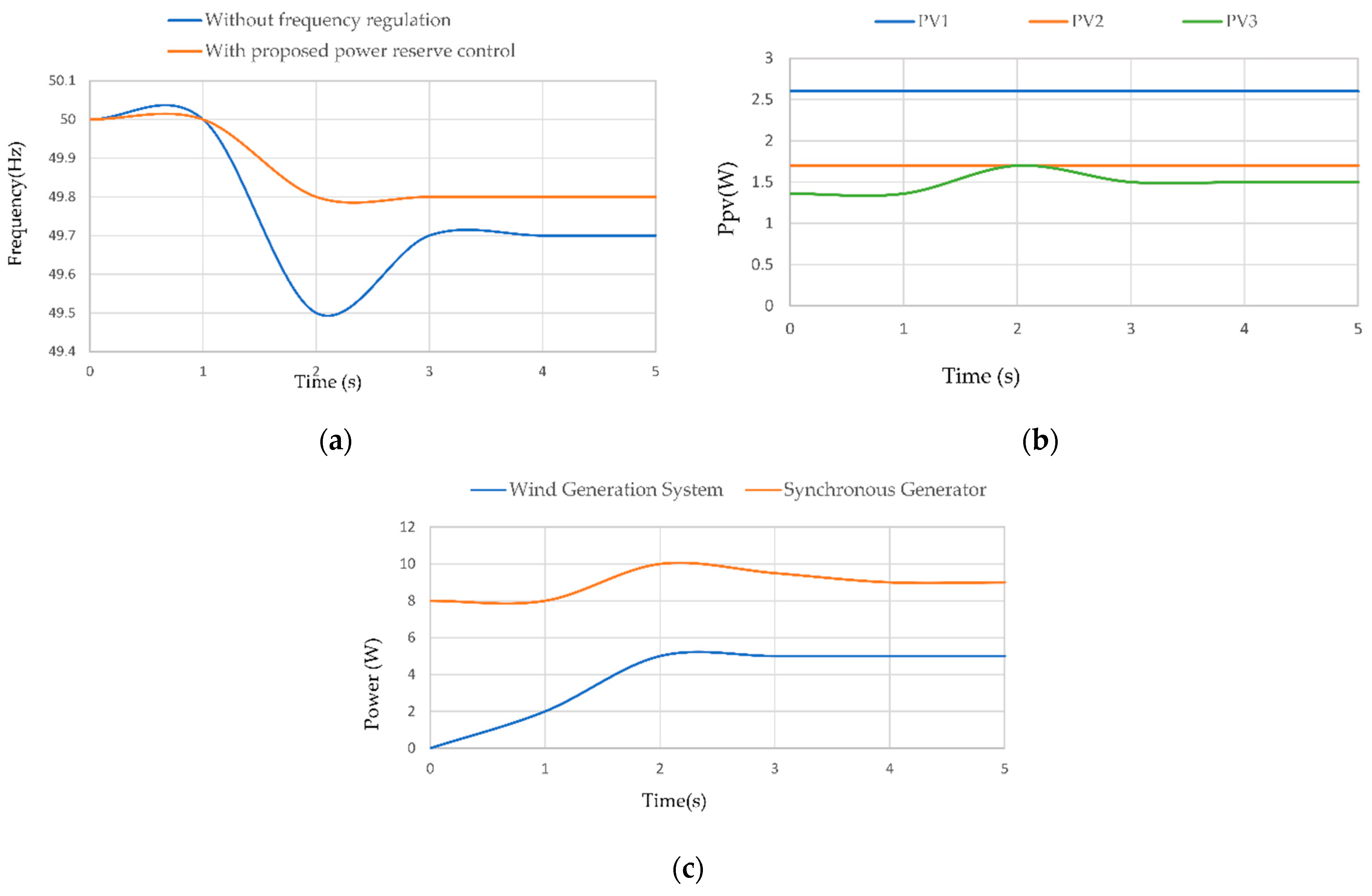
When the load L8 is incremented by 0.5 MW, the system frequency falls to 49.5 as seen in (blue plot) Figure 12a. When the load is incremented, there is no sufficient active power participation in the absence of the NN-FPPT control. When the control is applied, the frequency increases to 49.8; see (red plot) Figure 12a. The frequency control regulation block reduces the power reserve and brings the PV array to MPPT by increasing the voltage to the discharge/under-frequency region from the initial reserve of 1.36 MW to about 1.6 MW. As seen in Figure 12b,c, the WT, PV1, and PV2 continue to operate at rated values, while the synchronous machine shares in the frequency response along with PV2.

Discussions

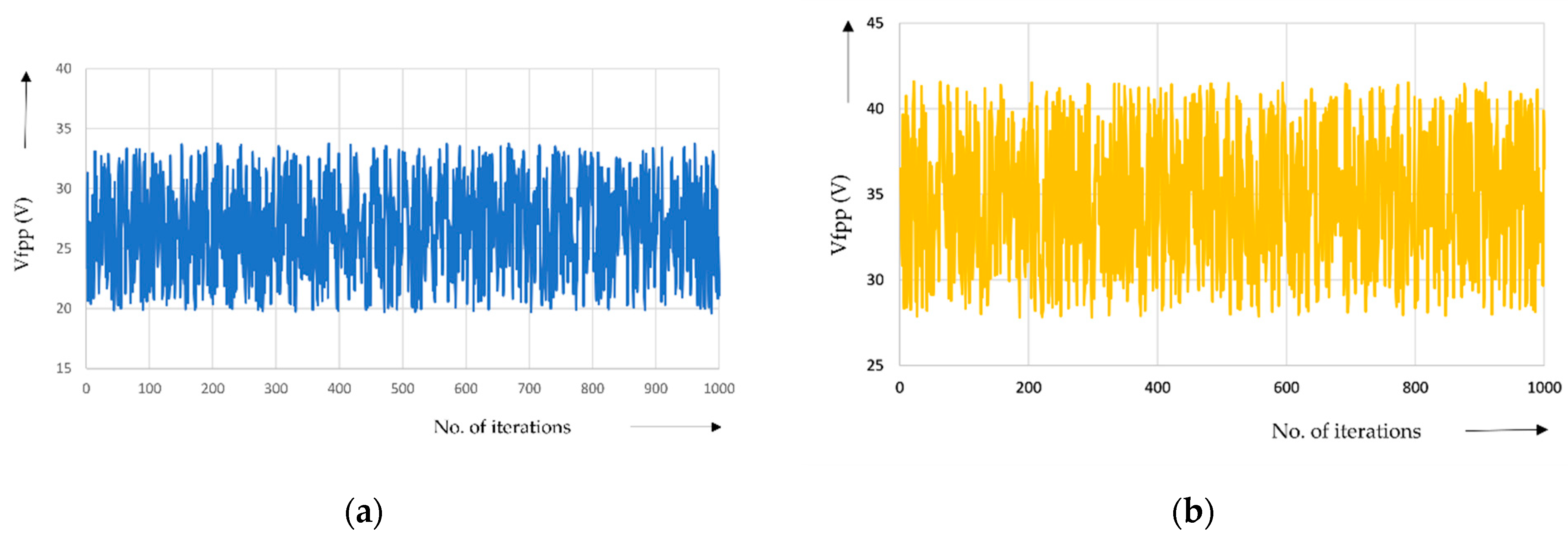
The main objective of the proposed control is to achieve frequency control with optimized outputs and high system stability. To verify the control objectives, the results are compared to the work done in [18,19]. For the proposed frequency control test, two cases are considered, for a 0.5 MW load decrement and 0.5 MW load increment, and as can be seen, the system frequency is maintained at 50.17 Hz and 49.85 Hz, respectively. In the absence of the virtual inertia control for PVs, the frequency increases to 50.84 Hz when the load is shed and the frequency reduces to 49.62 Hz when there is a generation load imbalance. For the control in [18], the operation of the PV array is on the right-hand side of the MPP to achieve almost similar frequency control. As discussed in earlier sections, this leads to system instability during fast irradiance changes. In the proposed control, the operation of PVs is restricted to the left side of the MPP so that the operating point will not reach the open circuit voltage. The open circuit voltage of the PV array in which the NN is tested is 37.5 V, as given in Table 1. From the waveform in Figure 13a, it is seen that the operating voltage for left-sided operation does not reach Voc. However, for the right-sided operation, the operating voltage crosses 37.3 V, subjecting the system to instability.
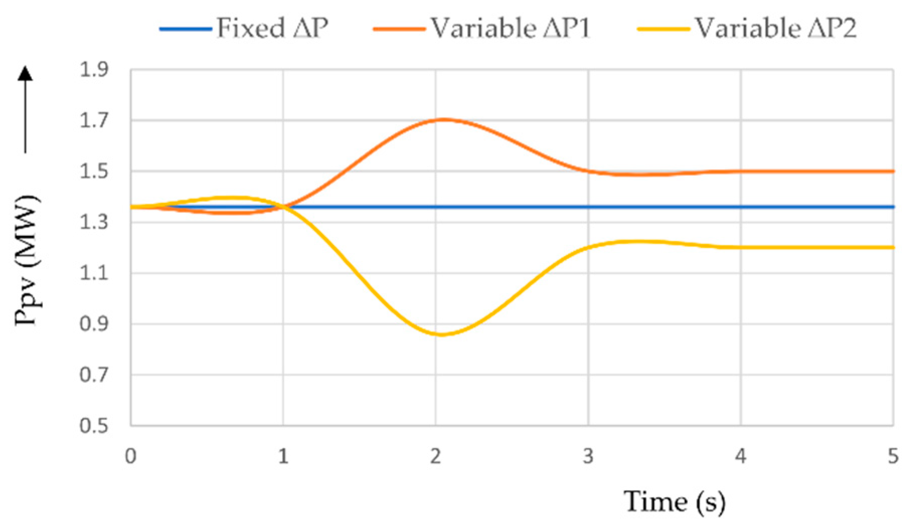
In [19], the PV is operated on the left side of the MPP, and delta power reserve control limits the power output of the PV array by a fixed value ∆P for all operating conditions. However, since the power reserve is constant, there is no frequency control, as is seen in Figure 14. The blue plot is the PV output of the control in [19] acts as a constant power generator. Thus, the stable left-hand-sided constant power generation in [19] is optimized in the proposed control by varying the power reserve for frequency control during load increment and decrement, as given by the red and yellow plots, respectively.
The advantages and limitations of the proposed method in comparison with control techniques used in [18,19] is summarized in Table 2.

5. Conclusions

In the absence of an energy reserve in the PV system, efficient active power control is necessary for improved system inertia response, and virtual energy storage is created for active power participation. This can be achieved through the flexible power point operation of the PV array as opposed to traditional fixed-point MPPT operation. The required power reserve is calculated by the frequency regulation controller, and the proposed NN-FPPT control estimates the operating voltage. The NN-FPPT is implemented using the MATLAB/Simulink NN block set system. The system is first tested with a 250 W array by using an NN system trained from random data varying between the maximum and minimum limits of irradiance, temperature, and power reserve. The controller is then implemented in a grid-connected two-level inverter PV system. The simulation is conducted on an IEEE-13 bus test system modeled in Simulink. The network has three PV panel arrays, two of which contribute to the system generation by operating in MPPT, and the third one provides inertia support through the proposed FPPT operation. The test is simulated by the increment and decrement of loads at 0.5 MW each. During load increment, the frequency drops, and the power reserve is discharged into the network for active power injection and restricts the frequency drop to 49.8 Hz as compared to the 49.5 Hz system frequency when there is no power reserve control. In the case of load increment, the frequency rises to about 50.8 Hz, and consequently, the reserve is increased to restrict active power injection into the grid, and the frequency rise is limited to about 50.2 Hz. The simulation results in the study confirm the inertia support by the PV array for up to 0.5 MW changes in load demand. Further improvement of the control system can be achieved through NN-FPPT training with actual system data and real-time operation on the utility grid.

Author Contributions

J.M.G. and P.K.S. have formulated the idea and converted it into an article. The authors confirm their contribution to the paper as follows: P.K.S. supervised the findings of this work. J.M.G. developed the theory and performed the computations, verified the analytical methods, and drafted the article. All authors have read and agreed to the published version of the manuscript.

Funding

This research received no external funding.

Data Availability Statement

The datasets used and analyzed during the current study are available from the corresponding author upon reasonable request. All the data analyzed during this study are included in this article itself.

Conflicts of Interest

The authors declare that the research was conducted in the absence of any commercial or financial relationships that could be construed as a potential conflict of interest.

References

  1. Tielens, P.; Van Hertem, D. The relevance of inertia in power systems. Renew. Sustain. Energy Rev. 2016, 55, 999–1009. [Google Scholar] [CrossRef]
  2. Hadjikypris, M.; Efthymiou, V.; Georghiou, G.E. Enhanced Frequency Response of Inverter Dominated Low Inertia Power Systems. In Proceedings of the 2019 1st International Conference on Energy Transition in the Mediterranean Area (Synergy Med), Cagliari, Italy, 28–30 May 2019; pp. 1–6. [Google Scholar] [CrossRef]
  3. Tamrakar, U.; Hansen, T.M.; Tonkoski, R.; Copp, D.A. Model Predictive Frequency Control of Low Inertia Microgrids. In Proceedings of the 2019 IEEE 28th International Symposium on Industrial Electronics (ISIE), Vancouver, BC, Canada, 12–14 June 2019; pp. 2111–2116. [Google Scholar] [CrossRef]
  4. Tamrakar, U.; Shrestha, D.; Maharjan, M.; Bhattarai, B.P.; Hansen, T.M.; Tonkoski, R. Virtual inertia: Current trends and future directions. Appl. Sci. 2017, 7, 654. [Google Scholar] [CrossRef] [Green Version]
  5. You, S. Photovoltaic (PV) Virtual Inertia and Fast Frequency Regulation in High PV Power Grids. arXiv 2020, arXiv:2010.11340. [Google Scholar]
  6. Rajan, R.; Fernandez, F.M.; Yang, Y. Primary frequency control techniques for large-scale PV-integrated power systems: A review. Renew. Sustain. Energy Rev. 2021, 144, 110998. [Google Scholar] [CrossRef]
  7. Nazih, A.; Osheba, D.S.M.; Mansour, A.S. Virtual inertia impact on the performance of photovoltaic system. In Proceedings of the 2019 IEEE Conference on Power Electronics and Renewable Energy (CPERE), Aswan, Egypt, 23–25 October 2019; pp. 7–11. [Google Scholar] [CrossRef]
  8. Rahmann, C.; Castillo, A. Fast frequency response capability of photovoltaic power plants: The necessity of new grid requirements and definitions. Energies 2014, 7, 6306–6322. [Google Scholar] [CrossRef]
  9. Liu, Y.; Zhu, L.; Zhan, L.; Gracia, J.R.; King, T.J.; Liu, Y. Active power control of solar PV generation for large interconnection frequency regulation and oscillation damping. Int. J. Energy Res. 2015, 40, 353–361. [Google Scholar] [CrossRef]
  10. Kakimoto, N.; Takayama, S.; Satoh, H.; Nakamura, K. Power modulation of photovoltaic generator for frequency control of power system. IEEE Trans. Energy Convers. 2009, 24, 943–949. [Google Scholar] [CrossRef]
  11. Akram, U.; Nadarajah, M.; Shah, R.; Milano, F. A review on rapid responsive energy storage technologies for frequency regulation in modern power systems. Renew. Sustain. Energy Rev. 2019, 120, 109626. [Google Scholar] [CrossRef]
  12. Zarina, P.P.; Mishra, S.; Sekhar, P.C. Deriving inertial response from a non-inertial PV system for frequency regulation. In Proceedings of the 2012 IEEE International Conference on Power Electronics, Drives and Energy Systems (PEDES), Bengaluru, India, 16–19 December 2012; pp. 1–5. [Google Scholar] [CrossRef]
  13. Rajan, R.; Fernandez, F.M. Power control strategy of photovoltaic plants for frequency regulation in a hybrid power system. Int. J. Electr. Power Energy Syst. 2019, 110, 171–183. [Google Scholar] [CrossRef]
  14. Zarina, P.; Mishra, S.; Sekhar, P. Exploring frequency control capability of a PV system in a hybrid PV-rotating machine-without storage system. Int. J. Electr. Power Energy Syst. 2014, 60, 258–267. [Google Scholar] [CrossRef]
  15. Gomez, J.M. Frequency and Inertia Response Effects, Capabilities, and Possibilities in Renewable Energy Sources. Recent Adv. Comput. Sci. Commun. 2022, 15, 1115–1139. [Google Scholar] [CrossRef]
  16. Gomez, J.M.; Shanmugam, P.K. Frequency response study in microgrid system with distributed generation having reduced inertia. In Proceedings of the 2020 IEEE International Women in Engineering (WIE) Conference on Electrical and Computer Engineering (WIECON-ECE), Bhubaneswar, India, 26–27 December 2020; pp. 183–190. [Google Scholar] [CrossRef]
  17. Gomez, J.M.; Shanmugam, P.K. Back-to- B ack Converter-Controlled Operation of Doubly F ed Induction Generator Wind Turbine and Solar Photovoltaic System. Innov. Power Adv. Comput. Technol. 2021, 2021, 1–6. [Google Scholar]
  18. Zhong, C.; Zhou, Y.; Yan, G. Power reserve control with real-time iterative estimation for PV system participation in frequency regulation. Int. J. Electr. Power Energy Syst. 2020, 124, 106367. [Google Scholar] [CrossRef]
  19. Sangwongwanich, A.; Yang, Y.; Blaabjerg, F.; Sera, D. Delta Power Control Strategy for Multistring Grid-Connected PV Inverters. IEEE Trans. Ind. Appl. 2017, 53, 3862–3870. [Google Scholar] [CrossRef] [Green Version]
  20. Hoke, A.; Muljadi, E.; Maksimovic, D. Real-time photovoltaic plant maximum power point estimation for use in grid frequency stabilization. In Proceedings of the 2015 IEEE 16th workshop on Control and Modeling for Power Electronics (COMPEL), Vancouver, BC, Canada, 12–15 July 2015; pp. 1–7. [Google Scholar] [CrossRef]
  21. Batzelis, E.I.; Kampitsis, G.E.; Papathanassiou, S.A. Power Reserves Control for PV Systems With Real-Time MPP Estimation via Curve Fitting. IEEE Trans. Sustain. Energy 2017, 8, 1269–1280. [Google Scholar] [CrossRef]
  22. Hiyama, T.; Kitabayashi, K. Neural network based estimation of maximum power generation from PV module using environmental information. IEEE Trans. Energy Convers. 1997, 12, 241–247. [Google Scholar] [CrossRef]
  23. Taherbaneh, M.; Faez, K. Maximum power point estimation for photovoltaic systems using neural networks. In Proceedings of the 2007 IEEE International Conference on Control and Automation, Guangzhou, China, 30 May–1 June 2007; pp. 1614–1619. [Google Scholar] [CrossRef]
  24. Baskarad, T.; Kuzle, I.; Holjevac, N. Photovoltaic System Power Reserve Determination Using Parabolic Approximation of Frequency Response. IEEE Trans. Smart Grid 2021, 12, 3175–3184. [Google Scholar] [CrossRef]
  25. Mishra, S.; Zarina, P.P.; Sekhar, P.C. A novel controller for frequency regulation in a hybrid system with high PV penetration. In Proceedings of the 2013 IEEE Power & Energy Society General Meeting, Vancouver, BC, Canada, 21–25 July 2013; pp. 1–5. [Google Scholar]
  26. Kim, D.; Park, J.-W.; Lee, S. A study on the power reserve of distributed generators based on power sensitivity analysis in a large-scale power system. Electronics 2021, 10, 769. [Google Scholar] [CrossRef]
  27. Tarraso, A.; Candela, J.I.; Rocabert, J.; Rodriguez, P. Synchronous power control for PV solar inverters with power reserve capability. In Proceedings of the IECON 2017-43rd Annual Conference of the IEEE Industrial Electronics Society, Beijing, China, 29 October–1 November 2017; pp. 2712–2717. [Google Scholar] [CrossRef] [Green Version]
  28. Tavakkoli, M.; Adabi, J.; Zabihi, S.; Godina, R.; Pouresmaeil, E. Reserve Allocation of Photovoltaic Systems to Improve Frequency Stability in Hybrid Power Systems. Energies 2018, 11, 2583. [Google Scholar] [CrossRef] [Green Version]
  29. Hoke, A.; Maksimovic, D. Active power control of photovoltaic power systems. In Proceedings of the 2013 1st IEEE Conference on Technologies for Sustainability (SusTech), Portland, OR, USA, 1–2 August 2013; pp. 70–77. [Google Scholar] [CrossRef]
  30. Sera, D.; Mathe, L.; Kerekes, T.; Spataru, S.V.; Teodorescu, R. On the perturb-and-observe and incremental conductance mppt methods for PV systems. IEEE J. Photovolt. 2013, 3, 1070–1078. [Google Scholar] [CrossRef]
  31. Wellawatta, T.R.; Seo, Y.-T.; Lee, H.-H.; Choi, S.-J. A regulated incremental conductance (r-INC) MPPT algorithm for photovoltaic system. In Proceedings of the 2017 IEEE Energy Conversion Congress and Exposition (ECCE), Cincinnati, OH, USA, 1–5 October 2017; pp. 2305–2309. [Google Scholar] [CrossRef]
  32. Sangwongwanich, A.; Yang, Y.; Blaabjerg, F.; Wang, H. Benchmarking of Constant Power Generation Strategies for Single-Phase Grid-Connected Photovoltaic Systems. IEEE Trans. Ind. Appl. 2017, 54, 447–457. [Google Scholar] [CrossRef] [Green Version]
  33. Yang, Y.; Wang, H.; Blaabjerg, F.; Kerekes, T. A hybrid power control concept for PV inverters with reduced thermal loading. IEEE Trans. Power Electron. 2014, 29, 6271–6275. [Google Scholar] [CrossRef]
  34. Rosa, C.; Vinikov, D.; Romero-Cadaval, E.; Pires, V.; Martins, J. Low-power home PV systems with MPPT and PC control modes. In Proceedings of the 2013 International Conference-Workshop Compatibility And Power Electronics, Ljubljana, Slovenia, 5–7 June 2013; pp. 58–62. [Google Scholar] [CrossRef]
  35. Urtasun, A.; Sanchis, P.; Marroyo, L. Limiting the power generated by a photovoltaic system. In Proceedings of the 2013 10th International Multi-Conference on Systems, Signals & Devices (SSD), Hammamet, Tunisia, 18–21 March 2013; pp. 1–6. [Google Scholar] [CrossRef]
  36. Tang, C.-Y.; Chen, Y.-T.; Chen, Y.-M. PV Power System with Multi-Mode Operation and Low-Voltage Ride-Through Capability. IEEE Trans. Ind. Electron. 2015, 62, 7524–7533. [Google Scholar] [CrossRef]
  37. Sangwongwanich, A.; Yang, Y.; Blaabjerg, F. Sensorless reserved power control strategy for two-stage grid-connected Photovoltaic systems. In Proceedings of the 2016 IEEE 7th international symposium on power electronics for distributed generation systems (PEDG), Vancouver, BC, Canada, 27–30 June 2016; pp. 1–8. [Google Scholar] [CrossRef] [Green Version]
  38. Bao, G.; Tan, H.; Ding, K.; Ma, M.; Wang, N. A novel photovoltaic virtual synchronous generator control technology without energy storage systems. Energies 2019, 12, 2240. [Google Scholar] [CrossRef]
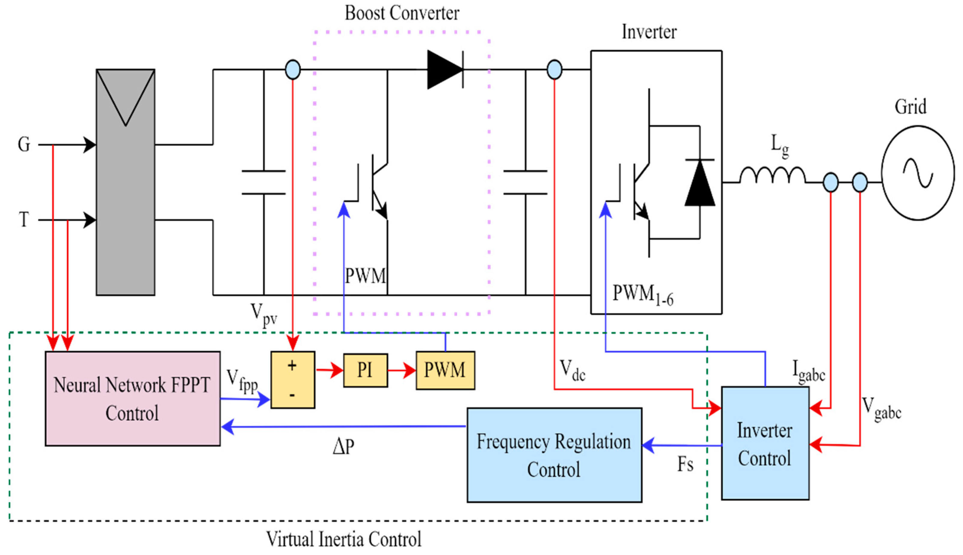
Figure 1. The photovoltaic two-level inverter system with proposed neural-network-based FPPT power reserve control for frequency regulation.
Energies 15 08234 g001
Figure 2. The frequency control regulation block.
Energies 15 08234 g002
Figure 3. The PV operating point characteristic for FPPT.
Energies 15 08234 g003
Figure 4. The FPPT control algorithm.
Energies 15 08234 g004
Figure 5. The neural network architecture.
Energies 15 08234 g005
Figure 6. The regression diagram for trained data.
Energies 15 08234 g006
Figure 7. System output waveforms when irradiance is fixed at 1000 W/m2 and temperature at 25 °C: (a) Power reserve ratio; (b) PV voltage; (c) PV output power.
Energies 15 08234 g007aEnergies 15 08234 g007b
Figure 8. System output waveforms when ∆P is fixed at 50 W and irradiance is varied from 200 W/m2 to 1000 W/m2: (a) Irradiance; (b) PV output voltage; (c) PV output power.
Energies 15 08234 g008
Figure 9. System output waveforms when irradiance and power reserve ratio are both varied: (a) Irradiance; (b) power reserve ratio; (c) PV output voltage; (d) PV output power.
Energies 15 08234 g009
Figure 10. IEEE-13 bus test system.
Energies 15 08234 g010
Figure 11. System output waveforms when the load is incremented by 0.5 MW: (a) Frequency; (b) PV output power; (c) output power of wind generation system and synchronous generator.
Energies 15 08234 g011
Figure 12. System output waveforms when the load is incremented by 0.5 MW: (a) Frequency; (b) PV power output; (c) output of wind generation system and synchronous generator.
Energies 15 08234 g012
Figure 13. The trained PV output voltages for (a) left-hand-side operation and (b) right-hand-side operation.
Energies 15 08234 g013
Figure 14. PV output voltage waveform for fixed and variable power reserve control.
Energies 15 08234 g014
Table 1. Parameters of PV array.
ParameterValue
Open circuit voltage under STC, VOC,STC37.3 V
Short circuit current under STC, ISC,STC8.6 A
Parallel resistance, Rsh313.0553 ohms
Series resistance, Rs0.3981 ohms
Open circuit voltage thermal correlation co-efficient, β0.86998
Short circuit current thermal correlation co-efficient, α−0.6901
Diode ideal factor, A0.98119
Table 2. Comparative study of the proposed control method with work from the existing literature.
Ref No.Power Reserve ControlAdvantages Limitations
Proposed Control
  • The maximum power available is estimated using the irradiance and temperature measurements.
  • The trained neural network generates the operating voltage of PVs corresponding to the necessary power reserve
  • The PV operating voltage changes dynamically by the trained NN control.
  • The PV operates on the left side of the MPP, ensuring that the operating voltage does not reach open circuit voltage.
  • The frequency regulation acts within 1 s.
The method requires temperature and irradiance sensors.
[18]
  • The maximum power available is estimated by sampling PV current and voltage.
  • The operating voltage is estimated as a function of the necessary power reserve.
It does not require irradiance and temperature sensors.
  • The PV Operates on the right-hand side of the MPP, subjecting the operating voltage of PVs to open circuit voltage that can cause system instability.
  • Frequency regulation within 5 s.
[19]
  • The master–slave maximum power estimation system is used where the power output of the master is the available maximum power.
  • The power reserve is the maximum available power minus the fixed reserve ∆P.
It does not require individual irradiance and temperature sensors.It does not change the power reserve following frequency deviations.
Publisher’s Note: MDPI stays neutral with regard to jurisdictional claims in published maps and institutional affiliations.