
Study on the Influence and Control of Stress Direction Deflection and Partial-Stress Boosting of Main Roadways Surrounding Rock and under the Influence of Multi-Seam Mining


Abstract
:1. Introduction
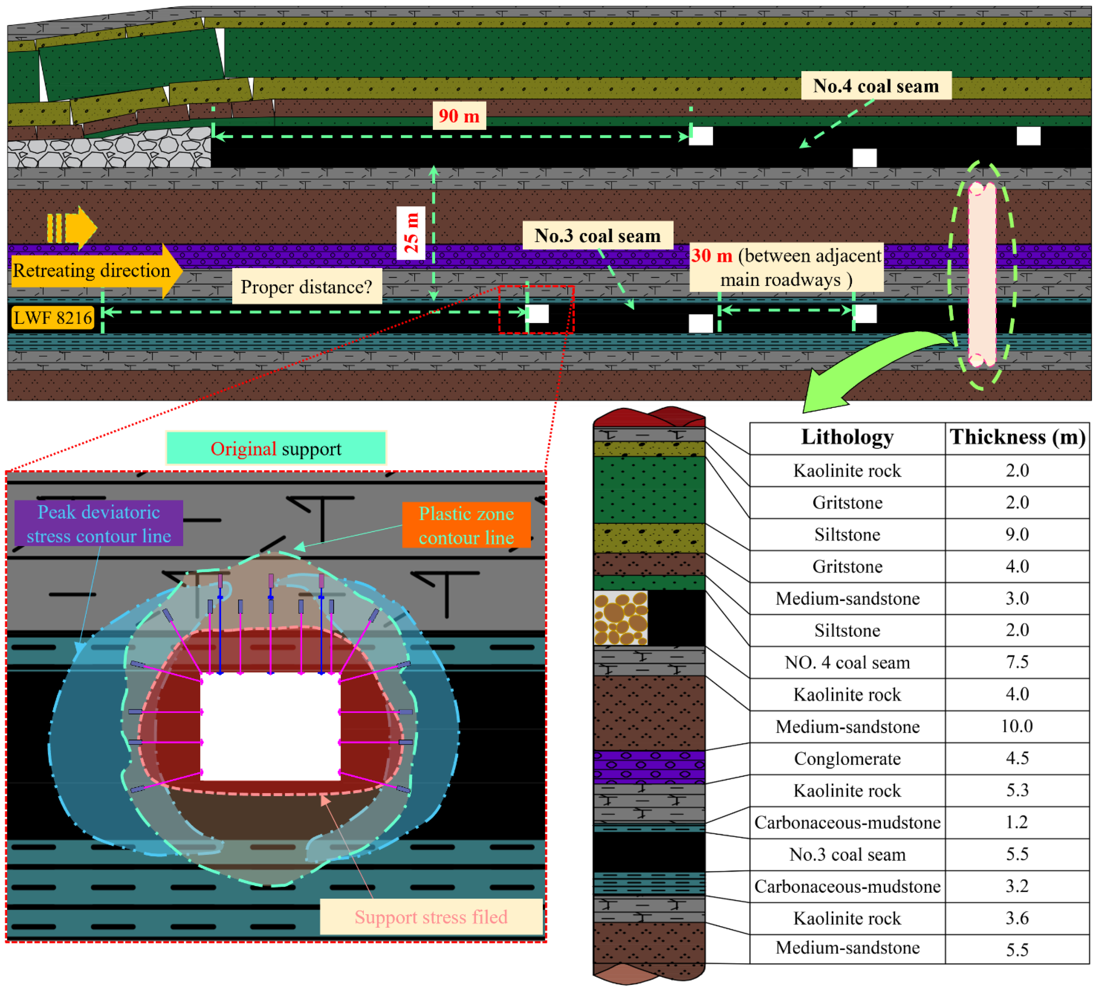
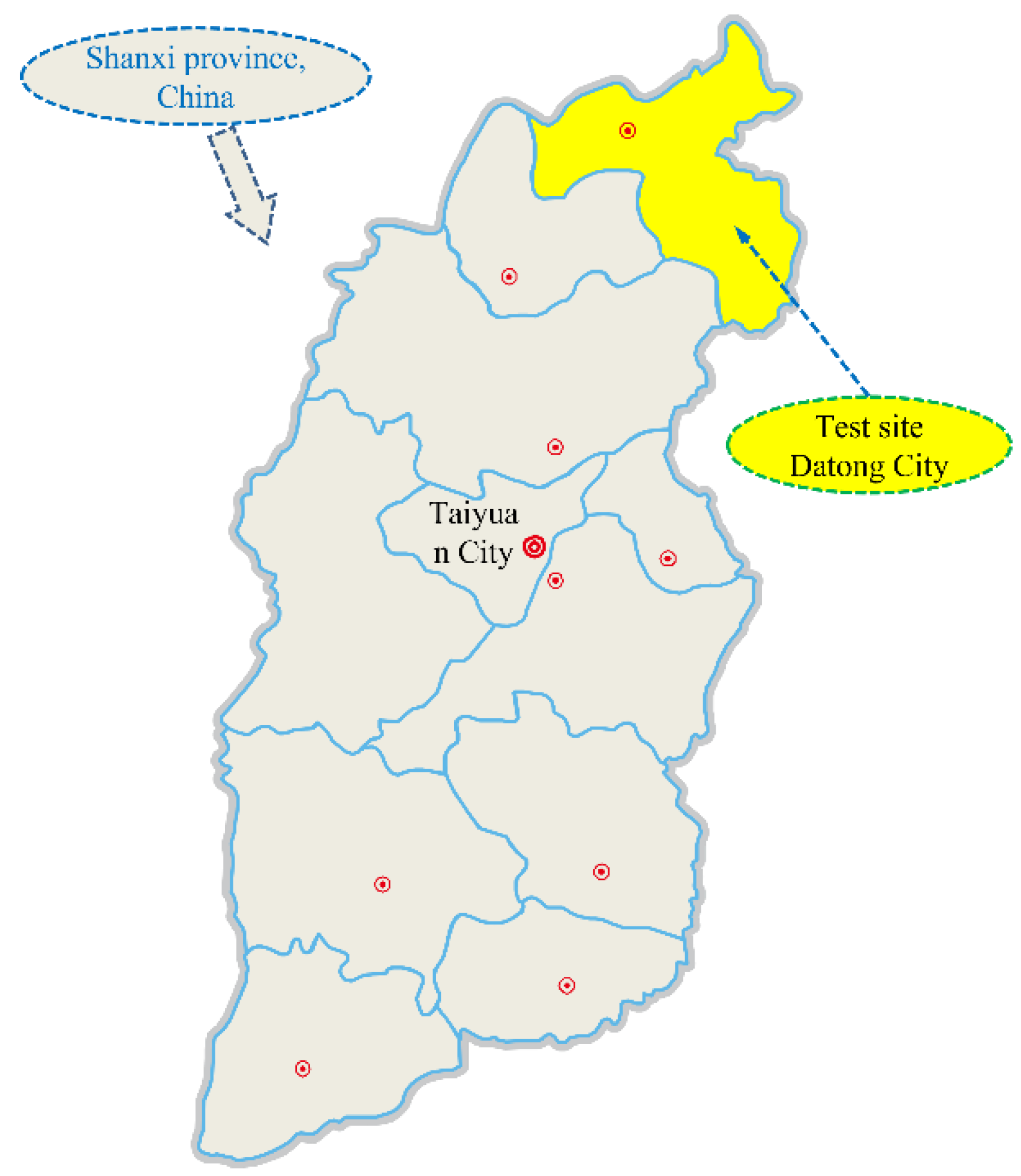
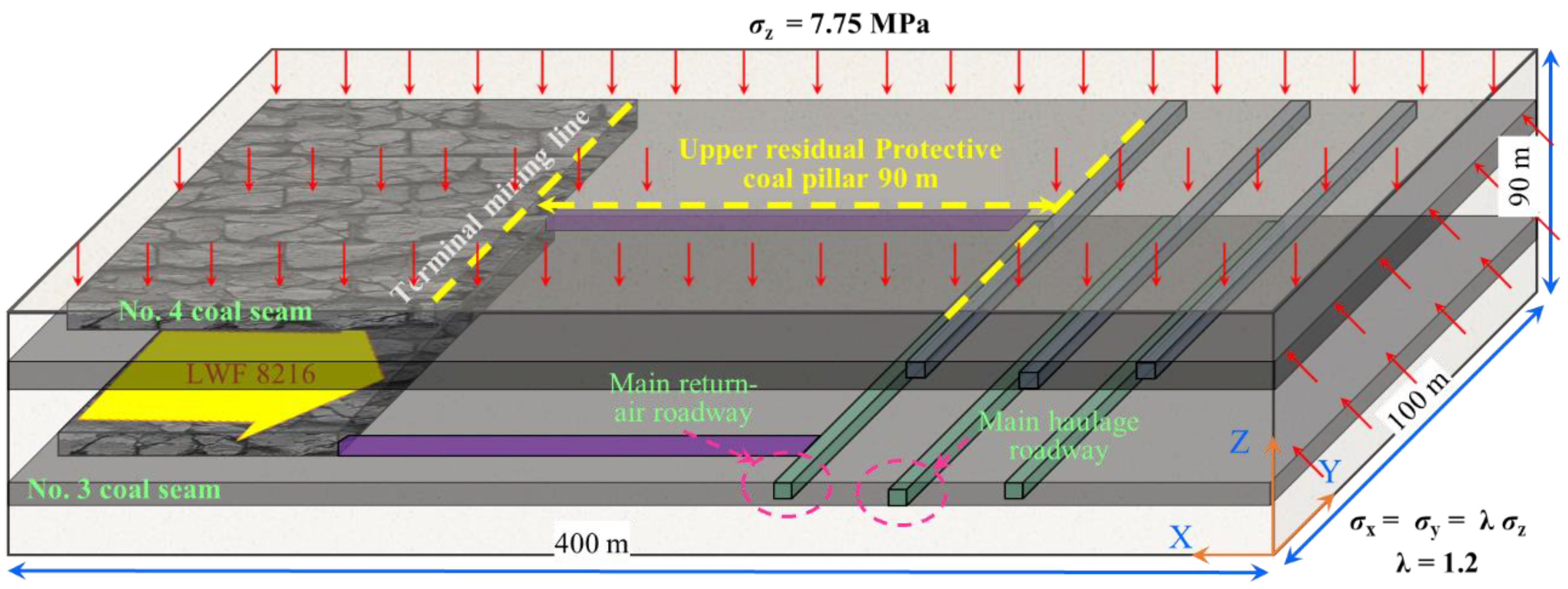
2. Project Overview
2.1. Geological Conditions
2.2. Description of the Mining Conditions
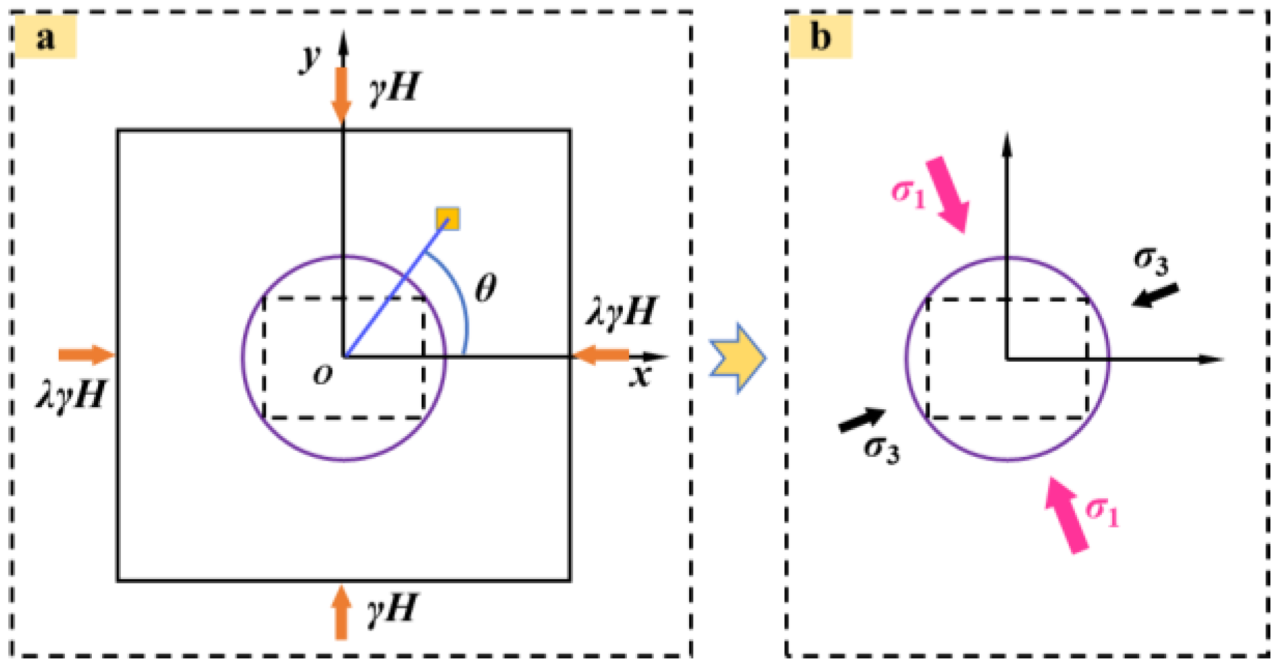
3. Theoretical Analysis of the Direction Deflection of the Stress and Partial-Stress Boosting in the Surrounding Rock
3.1. Solution for the Direction of Stress Deflection and Partial-Stress Boosting in the Mining Superposition Conditions
3.2. Solution for the Degree of the Stress Direction Deflection and the Partial-Stress Boosting and the Damage Analysis with the Disturbance of Multi-Seam Mining
4. Numerical Simulation
4.1. Stress Field Advance of the Working Face, Caused by Multi-Seam Mining
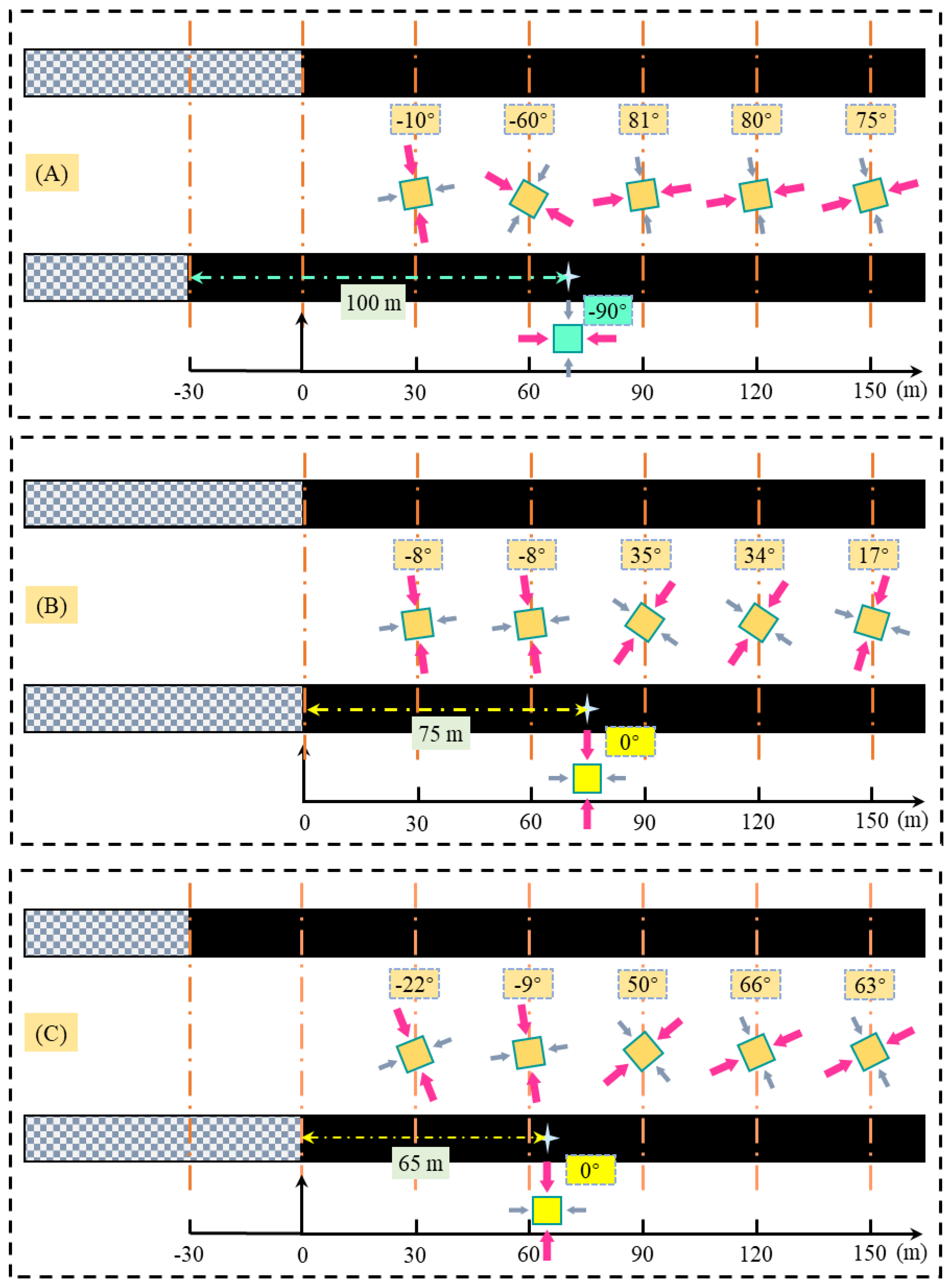
4.1.1. Deflection of the Principal Stress
- (1)
- The external staggered arrangement differs from the overlapping and internal staggered arrangement. The evolution trajectory of the maximum principal stress direction is approximately vertical → horizontal → deflection to the vertical direction in the external staggered arrangement; while that in the overlapping and internal staggered arrangement is approximately vertical → vertical → inclined to the two ribs.
- (2)
- The distance between the turning point of the maximum main stress direction (deflection angle of 0° or 90°) and the mining area, gradually decreases as the arrangement of the upper and lower coal seams changes from outer staggered type → overlapping type → internal staggered type. It is reasonable to adopt symmetrical support measures for the roadway at the turning point of the principal stress.
- (3)
- Under the condition of multi-seam mining, the maximum principal stress direction within 60 m in front of the lower coal seam is approximately vertical and deflected to the mining void. If the roadway is arranged here, the roadway surrounding rock will be damaged first along the direction of the minimum principal stress, namely the entity coal top angle of the roadway.
4.1.2. Direction Deflection of the Principal Stress
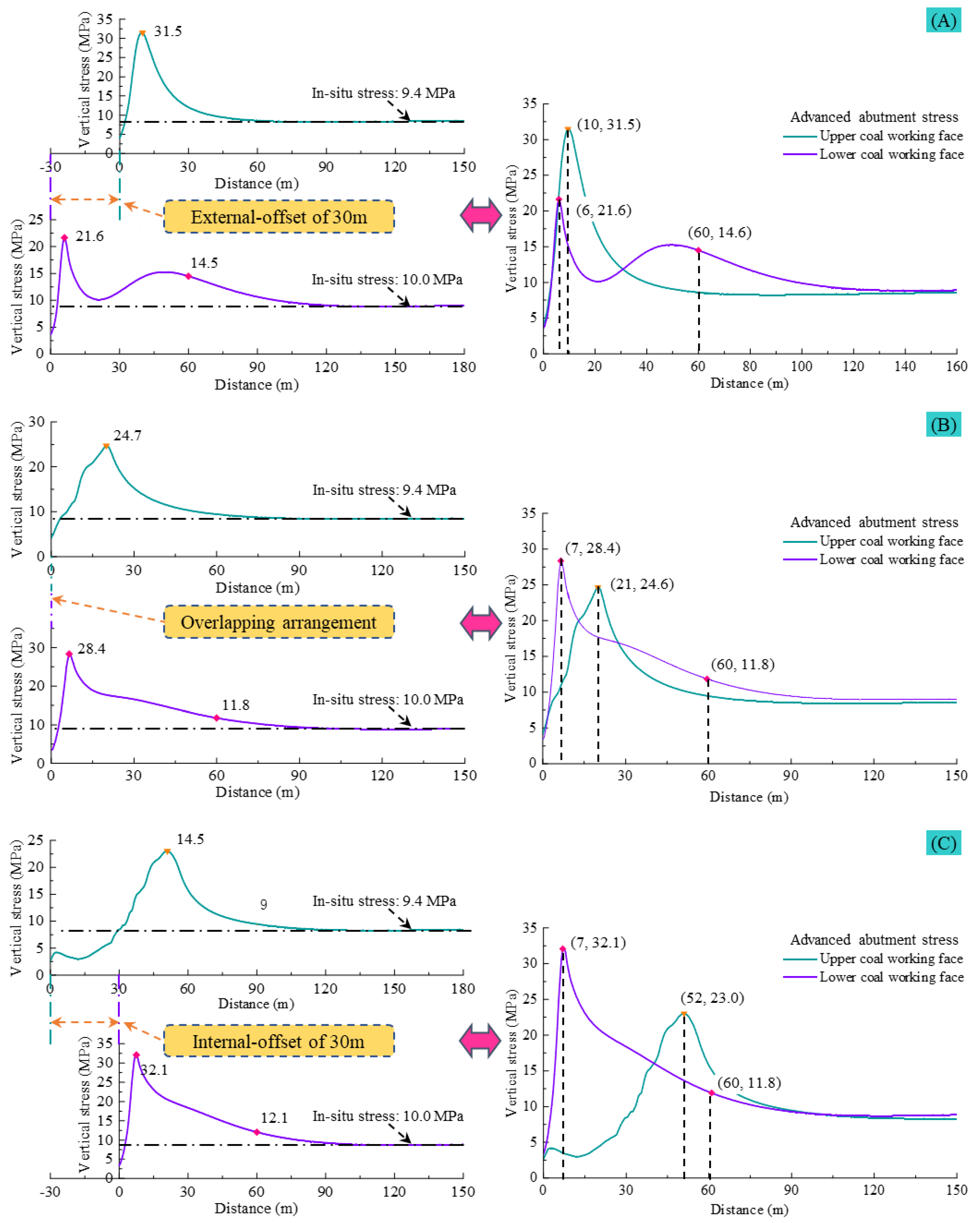
- (1)
- When the working face is staggered outward, the upper and lower coal seam abutment stress shows a trend of increasing to the peak first, then gradually stabilizing. The peak stress ratio between the lower and upper coal seam is Rs = 0.69, and the depth ratio is Rd = 0.6. When the working face of the lower coal seam is ahead by 60 m, the loading factor of the peak stress, compared with the original rock stress is L = 1.46. Furthermore, the abutment stress curve of the working face of the lower coal seam shows double peak characteristics, due to the position of the working face of the upper coal seam.
- (2)
- When the working face overlaps, the abutment stress trend in the upper and lower coal seams increases first and then decreases. The ratio of the peak stress between the lower coal seam and upper coal seam is Rs = 1.15, and the depth ratio is Rd = 0.33; when the working face of the lower coal seam is ahead by 60 m, the stress peak, compared to the original rock stress has a loading factor of L = 1.18.
- (3)
- When the working face is staggered internally, the trend of the abutment stress in the upper and lower coal seams still increases first and then decreases. The ratio of the peak stress between the lower and upper coal seams is Rs = 1.40, and the depth ratio is Rd = 0.13; when the working face of the lower coal seam is ahead by 60 m, the loading factor of the peak stress, compared with the original rock stress is L = 1.18.
- (4)
- In the process of the upper and lower working face from the outer fault → overlap → inner fault arrangement, the abutment stress peak of the lower coal seam working face increases continuously, and the value is gradually larger than that of the upper coal seam. The peak stress in the upper coal seam is the opposite of the peak stress in the upper coal seam. The peak stress depth of the lower coal seam does not change much and remains at a 6 to 7 m depth. In contrast, the peak stress depth in the upper coal seam is significantly affected by the working face layout, and the depth increases from 10 m to 52 m, an increase of 520%.
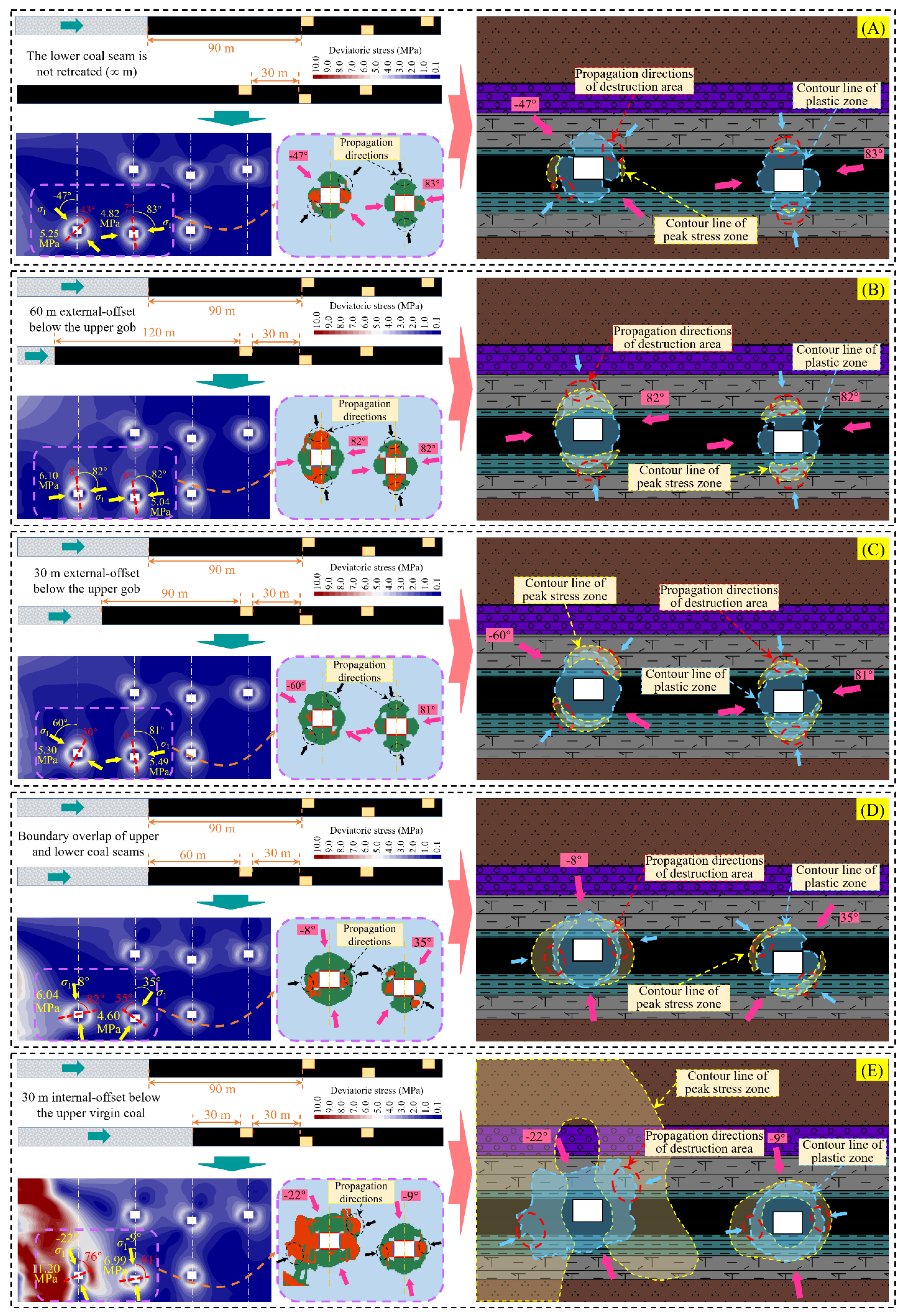
4.2. Roadway Group Stress Field Characteristics under Various Protective Coal Pillars
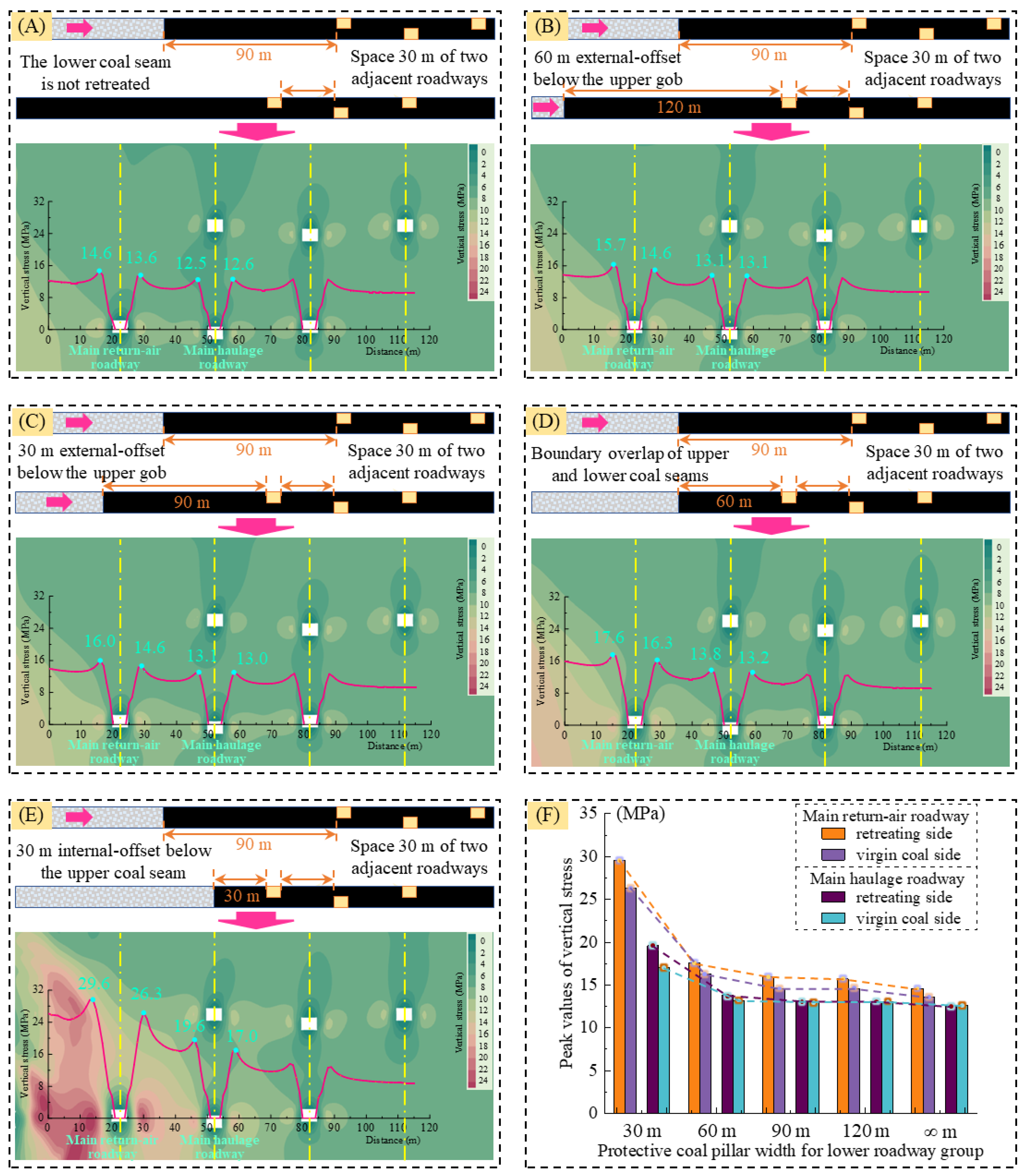
- (1)
- When the end-mining coal pillar of the upper coal seam is 90 m, the protective coal pillar’s width of the lower coal seam main roadway reduces from ∞ m (which means that the lower coal seam is not mined) to 30 m, the abutment stress’ peak of the lower coal seam main roadway group is gradually increasing. The maximum loading increase factor is L = 2.03. Furthermore, when the width of the coal pillar is less than 60 m (i.e., the overlapping arrangement of the upper and lower coal seams), the stress of the main roadway surrounding rock increases sharply.
- (2)
- The surrounding rock of the main roadway group shows a typical asymmetric effect of the direction deflection of the stress and partial-stress boosting. The peak stress of the mining side is more extensive than its entity coal side of the main return-air roadway and main haulage roadway, and the degree of stress direction deflection and partial-stress boosting increases with the shortening of the end-mining coal pillar width. The direction deflection of stress and the partial-stress boosting phenomenon of the main roadway group surrounding rock shows that the stress distribution of the surrounding rock is asymmetric, so it is necessary to use targeted support solutions in some places where the surrounding rock is weak.
4.3. Law of Stress Direction Deflection and Partial-Stress Boosting of the Deviatoric Stress Field of the Surrounding Rock with Different End-Mining Coal Pillar Widths
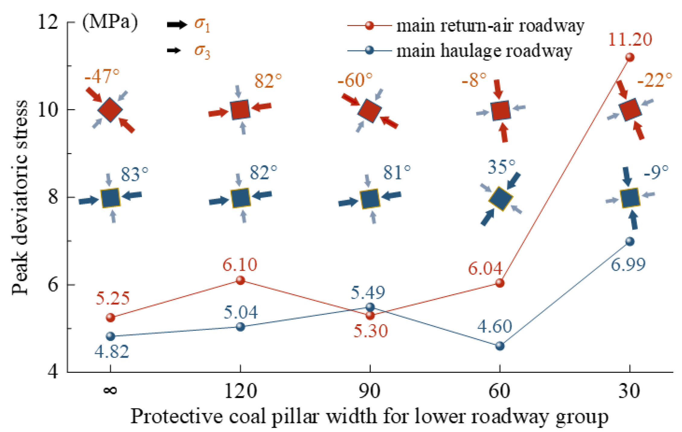
- (1)
- The peak value of deviatoric stress shows an overall increasing trend with advancing the lower coal seam workings. When the width of the end-mining coal pillar is from ∞ m → 60 m → 30 m, the peak value of deviatoric stress in the main return-air roadway is from 5.25 MPa → 6.04 MPa → 11.20 MPa. The maximum stress loading factor is L = 2.1, and the peak value of the deviatoric stress in the main haulage roadway is from 4.82 MPa → 4.60 MPa → 6.99 MPa, and the maximum stress loading factor is L = 1.45. When the width of the lower end-mining coal pillar is more than 60 m, the peak value of the deviatoric stress in the main roadway group is more fluctuating. When the width of the lower end-mining coal pillar is bigger than 60 m, the peak value of the deviatoric stress in the main roadway group is more fluctuating, indicating that the peak distribution is not significantly affected by the larger width of the end-mining coal pillar.
- (2)
- The peak deviatoric stress area gradually expands during the gradual decrease of the lower coal seam end-mining coal pillar width. As the influence of mining intensifies, the peak deviatoric stress area gradually surrounds the roadway surrounding rock and shows an apparent directional deflection. The location of the peak zone gradually transitions from the roof and floor to both ribs of the roadway. The plastic zone’s contour line of the roadway passes through the core area of the peak of the deviatoric stress. Furthermore, the plastic zone evolution direction also has obvious directionality; with the minimum principal stress direction deflection, the plastic zone development position occurs with a corresponding shift.
- (3)
- The maximum principal stress direction shows a significant deflection with the advancing lower coal seam workings (main return-air roadway). With the increase of the distance of the main roadway from the gob area, the direction of the maximum principal stress gradually transitions from the direction of the deflected gob area to the direction of the deflected entity coal. The direction of the minimum principal stress passes through the center of the peak deviatoric stress area of the two ribs of the roadway. The location of the peak of the deviatoric stress shows a significant asymmetry, and this type is to be avoided in the actual project.
- (4)
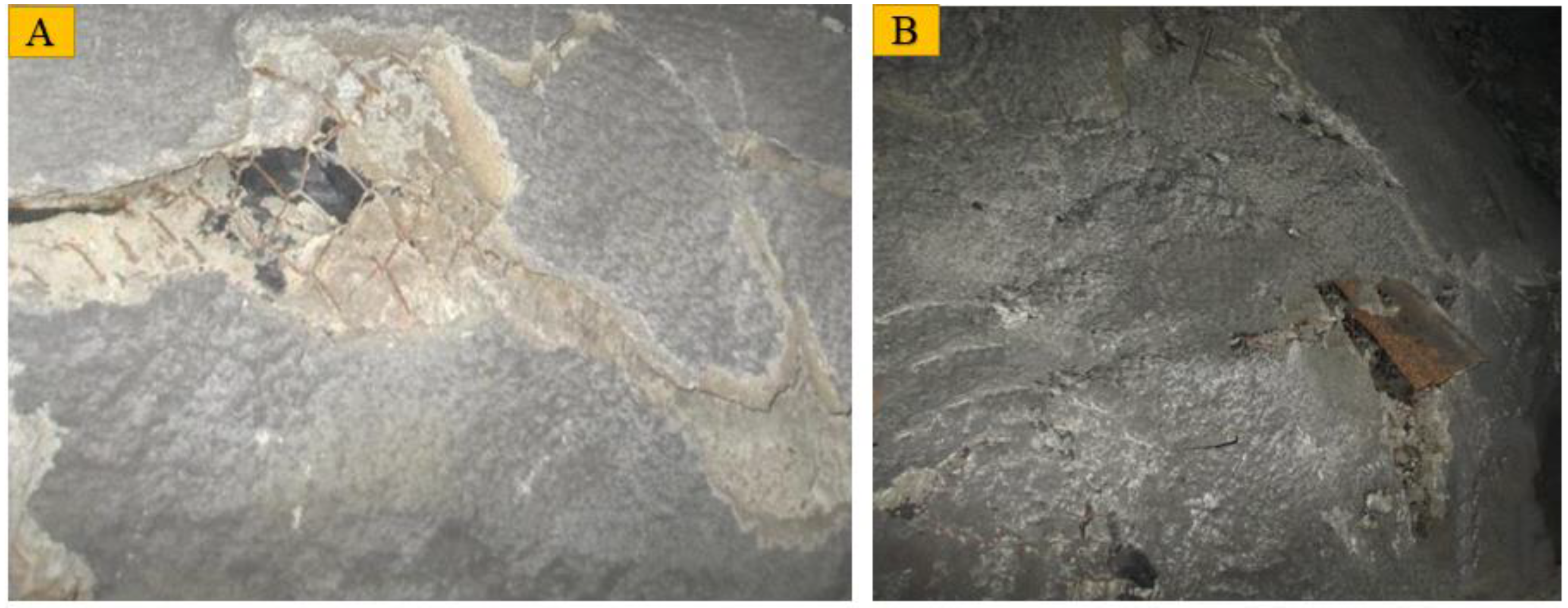
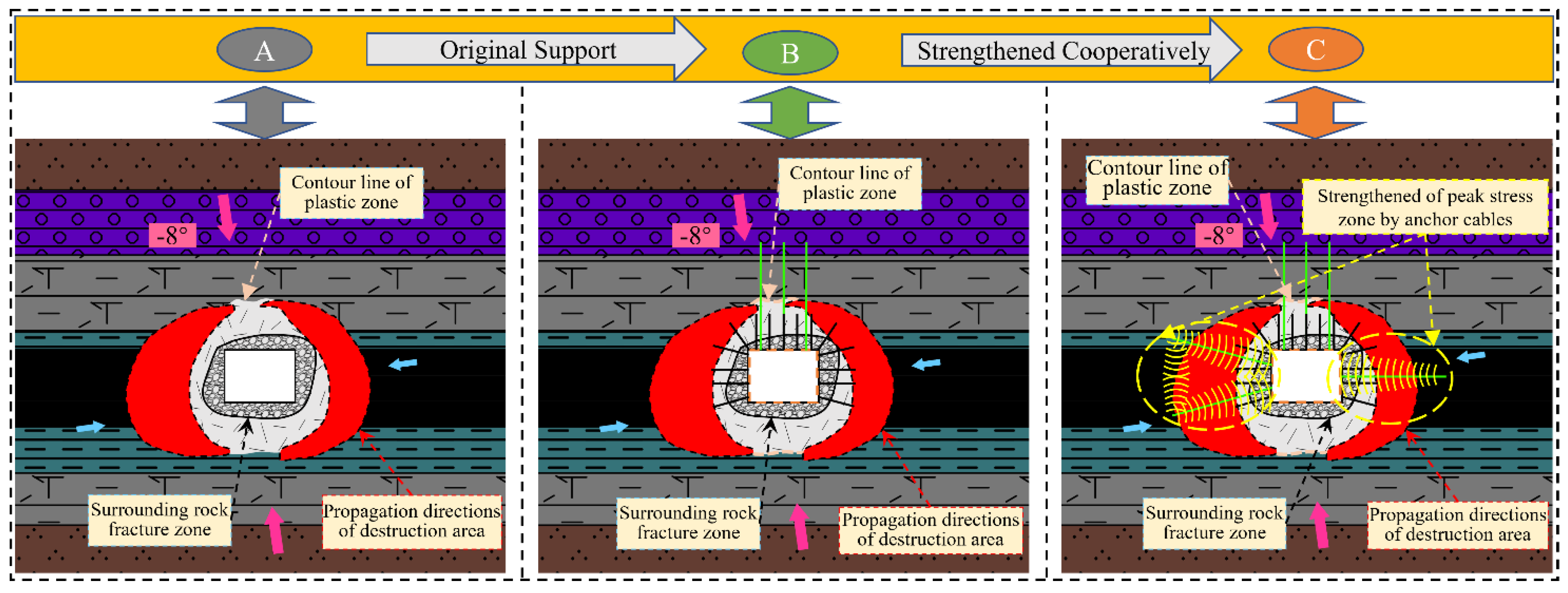
- When the width of the end-mining coal pillar in the lower seam is 60 m, the direction of the maximum principal stress of the main return-air roadway is approximately perpendicular to the roof and floor of the roadway (deflected 8° toward the side of the gob area). That means the direction of the minimum principal stress in the roadway points to the entity coal top angle of the roadway, which also corresponds to the direction of the development of the plastic zone in the roadway. The failure results of the main roadway by a numerical simulation are consistent with the failure position of the main roadway under field working conditions, and the failure mechanism of the surrounding rock of the roadway is well revealed. This is conducive to applying an early warning and asymmetric control technology for the deformation orientation of the main roadway surrounding rock.
5. Surrounding Rock Control Techniques
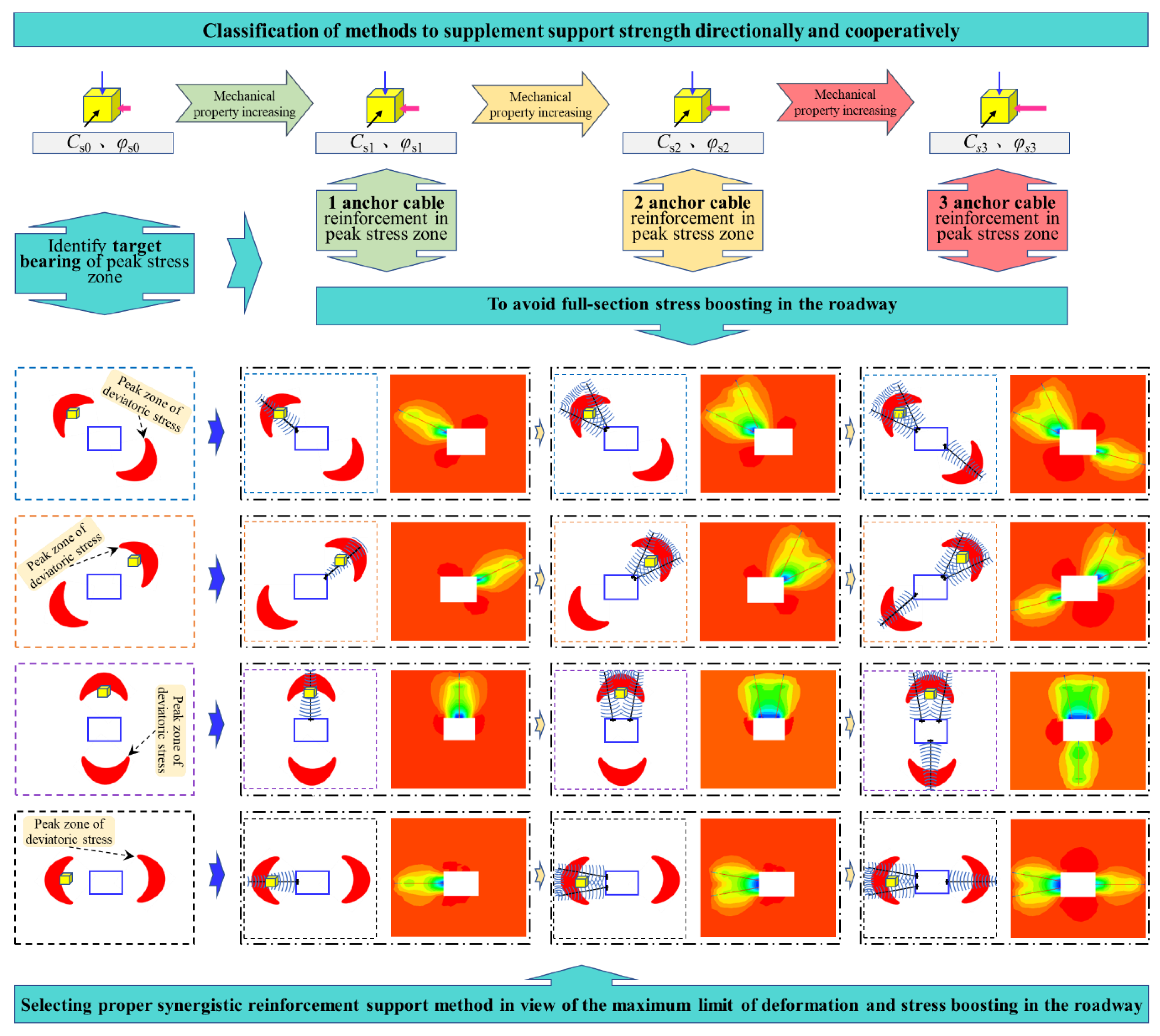
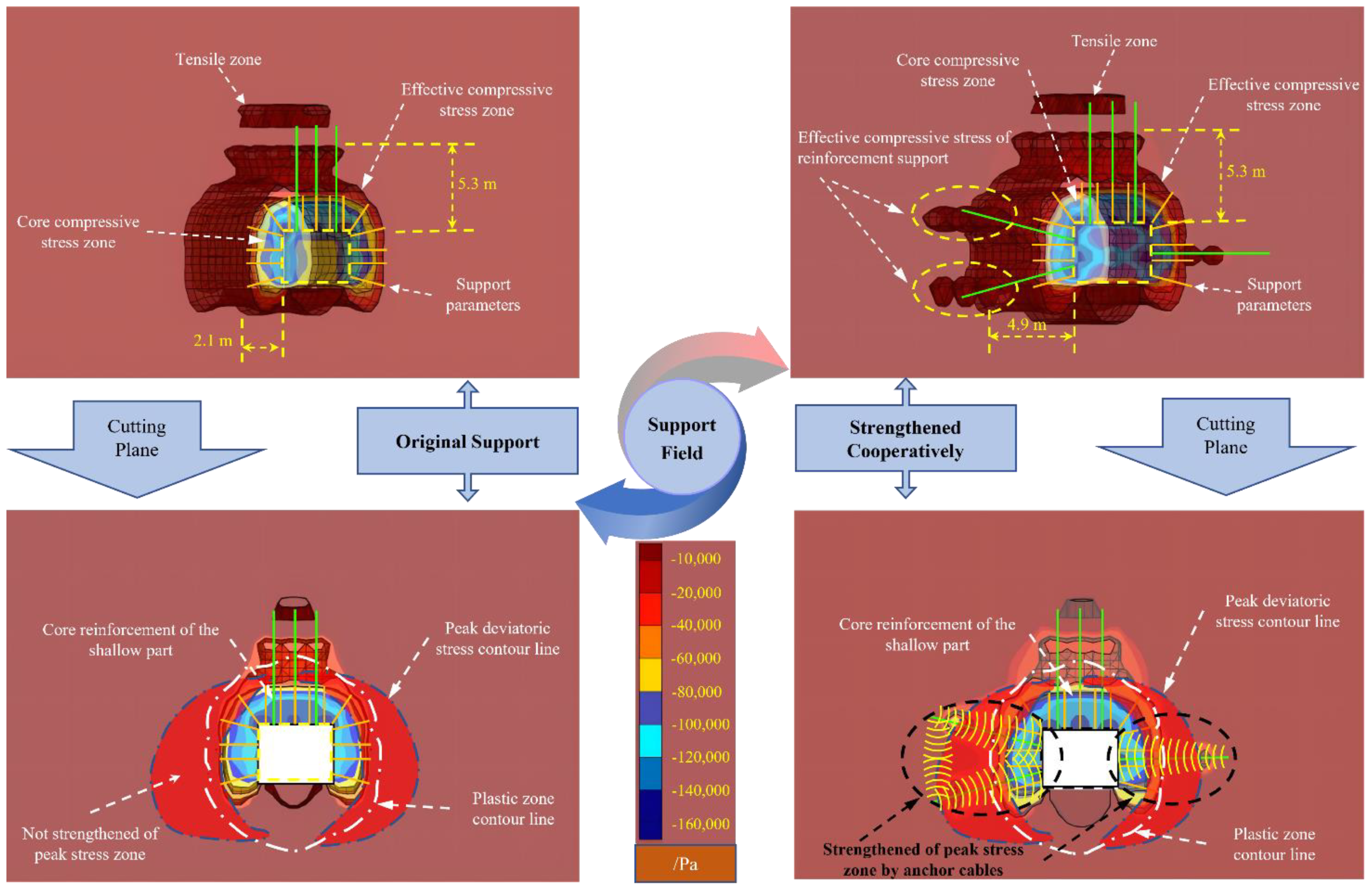
5.1. Principle of the Asymmetric Reinforcement Support Cooperation
5.2. Support Parameters
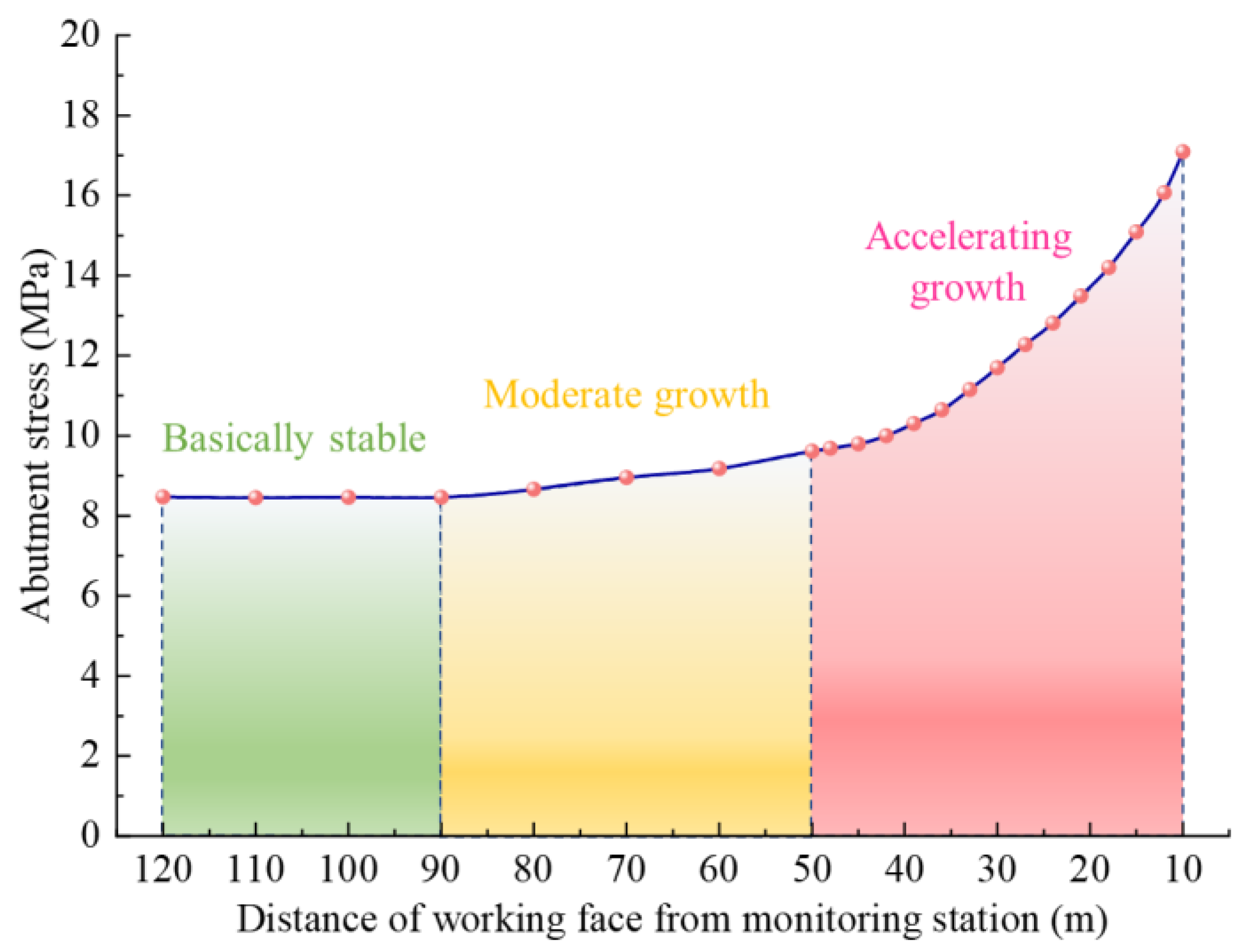
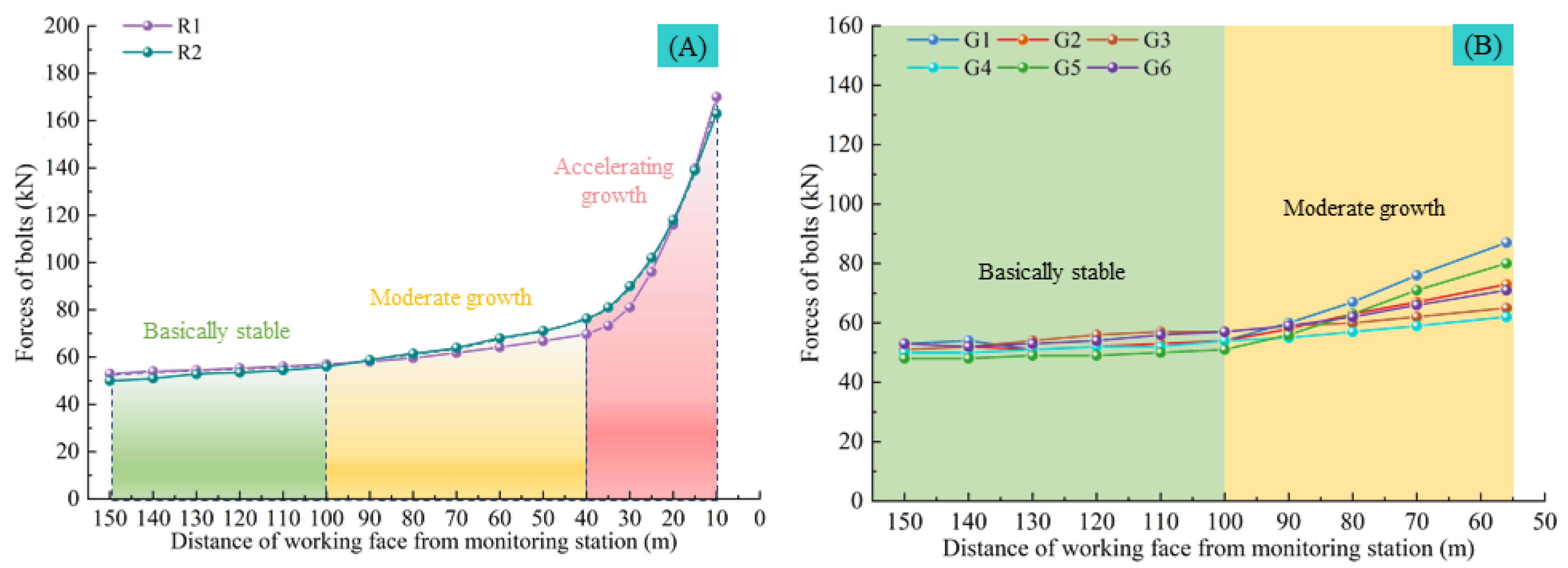
5.3. Ground Pressure Monitoring
6. Conclusions
- (1)
- Mining-induced stress prompted two modes of critical zones of the deviatoric stress in the roadway. When the extent of the partial-stress boosting is weak, the critical zones of the deviatoric stress in the roadway mainly developed symmetrically in two directions of the roadway. While the extent of the partial-stress boosting was strong, the critical zones of the deviatoric stress were symmetrically distributed on both sides of the roadway, and the damaged area tended to develop from four directions to the deep part of the surrounding rock.
- (2)
- With the influence of the multi-seam mining activities, the stress fields in the main roadway showed an asymmetric effect of the partial-stress boosting, and as the end-mining coal pillar width in the lower coal seam was shortened, the extent of partial-stress boosting increased. The direction of the maximum principal stress in the roadway showed a significant characteristic of deflection, and the peak points of the stress field were asymmetrically distributed.
- (3)
- On-site mine pressure monitoring showed that when the upper and lower working faces overlapped, the mining stress tended to be significantly enhanced in the range of 40~50 m in front of the lower coal seam working face. Once the lower working face was stopped at 56 m from the main roadway, the surrounding rock of both ribs, especially the mining side, was more sensitive to the impact of mining.
Author Contributions
Funding
Conflicts of Interest
References
- Jia, H.; Li, T.; Wang, A.; Liu, G.; Guo, X. Decoupling analysis of economic growth and mineral resources consumption in China from 1992 to 2017: A comparison between tonnage and exergy perspective. Resour. Policy 2021, 74, 102448. [Google Scholar] [CrossRef]
- Zou, C.; Xiong, B.; Xue, H.; Zheng, D.; Ge, Z.; Wang, Y.; Jiang, L.; Pan, S.; Wu, S. The role of new energy in carbon neutral. Pet. Explor. Dev. 2021, 48, 480–491. [Google Scholar] [CrossRef]
- Cao, J.W.; Zhang, W.; Li, Y.; Zhao, C.; Zheng, Y.; Yu, B. Current Status of Hydrogen Production in China. Prog. Chem. 2021, 33, 2215–2244. [Google Scholar] [CrossRef]
- Jiachen, W.; Peng, S.; Yang, L. State of the art in underground coal mining and automation technology in the United States. J. China Coal Soc. 2021, 46, 36–45. [Google Scholar] [CrossRef]
- Peng, S.S.; Du, F.; Cheng, J.Y.; Li, Y. Automation in U.S. longwall coal mining: A state-of-the-art review. Int. J. Min. Sci. Technol. 2019, 29, 151–159. [Google Scholar] [CrossRef]
- Ghosh, N.; Agrawal, H.; Singh, S.K.; Banerjee, G. Optimum Chain Pillar Design at the Deepest Multi-Seam Longwall Workings in India. Min. Metall. Explor 2020, 37, 651–664. [Google Scholar] [CrossRef]
- Bruce, H.; Jim, G. A review of the geomechanics aspects of a double fatality coal burst at Austar Colliery in NSW, Australia in April 2014. Int. J. Min. Sci. Technol. 2017, 27, 3–7. [Google Scholar] [CrossRef]
- Pariseau, W.G.; Larson, M.K.; Lawson, H.E.; Tesarik, D.R. User-friendly finite element design of main entries, barrier pillars, and bleeder entries. Int. J. Min. Sci. Technol. 2018, 28, 3–10. [Google Scholar] [CrossRef]
- Gao, F.Q.; Stead, D.; Kang, H.P.; Wu, Y.Z. Discrete element modelling of deformation and damage of a roadway driven along an unstable goaf-A case study. Int. J. Coal Geol. 2014, 127, 100–110. [Google Scholar] [CrossRef]
- Gao, F.; Stead, D.; Kang, H. Simulation of roof shear failure in coal mine roadways using an innovative UDEC Trigon approach. Comput. Geotech. 2014, 61, 33–41. [Google Scholar] [CrossRef]
- Gao, F.Q.; Stead, D.; Kang, H.P. Numerical Simulation of Squeezing Failure in a Coal Mine Roadway due to Mining-Induced Stresses. Rock Mech. Rock Eng. 2015, 48, 1635–1645. [Google Scholar] [CrossRef]
- Wang, X.F.; Wang, J.Y.; Chen, X.Y.; Chen, Z.C. A Roadway In Close Distance to coal seam in deep mine: Location selection and supporting practice based on creep characteristics of surrounding rocks. Arch. Min. Sci. 2021, 66, 407–419. [Google Scholar] [CrossRef]
- Pan, S.Q.; Liu, S.T.; Cao, L.M.; Guo, J.Q.; Yuan, C. Deformation Failure and Support Test of Surrounding Rock in Deep Arched Roadway with Straight Wall. Adv. Civ. Eng. 2021, 2021, 11. [Google Scholar] [CrossRef]
- Mohammadi, H.; Ebrahimi Farsangi, M.A.; Jalalifar, H.; Ahmadi, A.R. A geometric computational model for calculation of longwall face effect on gate roadways. Rock Mech. Rock Eng. 2016, 49, 303–314. [Google Scholar] [CrossRef]
- Huang, B.; Zhang, N.; Jing, H.; Kan, J.; Meng, B.; Li, N.; Xie, W.; Jiao, J. Large deformation theory of rheology and structural instability of the surrounding rock in deep mining roadway. J. China Coal Soc. 2020, 45, 911–926. [Google Scholar]
- Xiong, Y.; Kong, D.; Cheng, Z.; Wen, Z.; Ma, Z.; Wu, G.; Liu, Y. Instability Control of Roadway Surrounding Rock in Close-Distance Coal Seam Groups under Repeated Mining. Energies 2021, 14, 5193. [Google Scholar] [CrossRef]
- Shan, R.; Peng, Y.; Kong, X.; Li, H. Research progress of coal roadway support technology at home and abroad. Chin. J. Rock Mech. Eng. 2019, 38, 2377–2403. [Google Scholar]
- Chen, D.; Xie, S.; Wu, Y.; Guo, F.; He, F.; Liu, R. Reasonable location of stopping line in close-distance underlying coal seam and partition support of large cross-section roadway. Int. J. Coal. Sci. Technol. 9. [CrossRef]
- Yuan, W.; Hong, K.; Liu, R.; Ji, L.; Meng, L. Numerical Simulation of Coupling Support for High-Stress Fractured Soft Rock Roadway in Deep Mine. Adv. Civ. Eng. 2022, 16, 1–10. [Google Scholar]
- Yuan, Y.; Wang, W.J.; Yuan, C.; Yu, W.J.; Peng, W.Q. Large deformation failure mechanism of surrounding rock for gateroad under dynamic pressure in deep coal mine. J. China Coal Soc. 2016, 41, 2940–2950. [Google Scholar]
- Xie, S.; Wang, E.; Chen, D.; Jiang, Z.; Li, H.; Liu, R. Collaborative control technology of external anchor-internal unloading of surrounding rock in deep large-section coal roadway under strong mining influence. J. China Coal Soc. 2022, 47, 1946–1957. [Google Scholar]
- Liu, S.; Yang, K.; Tang, C. Asymmetric failure mechanism and control of downhill roadway group of soft rock in deep mine. J. Min. Saf. Eng. 2019. [Google Scholar] [CrossRef]
- Li, G.; Sun, Y.; Zhang, J.; Zhang, Q.; Sun, C.; Zhang, S.; Bi, R. Experiment and application of coalcrete on roadway stability: A comparative analysis. Adv. Mater. Sci. Eng. 2020, 2020, 1–14. [Google Scholar] [CrossRef]
- Sun, Y.; Bi, R.; Sun, J.; Zhang, J.; Taherdangkoo, R.; Huang, J.; Li, G. Stability of roadway along hard roof goaf by stress relief technique in deep mines: A theoretical, numerical and field study. Geomech. Geophys. Geo-Energy Geo-Resour. 2022, 8, 1–16. [Google Scholar] [CrossRef]
- Xie, S.; Guo, F.; Wu, Y. Control Techniques for Gob-Side Entry Driving in an Extra-Thick Coal Seam with the Influence of Upper Residual Coal Pillar: A Case Study. Energies 2022, 15, 3620. [Google Scholar] [CrossRef]
- Wang, E.; Xie, S. Determination of coal pillar width for gob-side entry driving in isolated coal face and its control in deep soft-broken coal seam: A case study. Energy Sci. Eng. 2022, 10, 2305–2316. [Google Scholar] [CrossRef]
- Zhang, Z.; Bai, J.; Chen, Y.; Yan, S. An innovative approach for gob-side entry retaining in highly gassy fully-mechanized longwall top-coal caving. Int. J. Rock Mech. Min. Sci. 2015, 80, 1–11. [Google Scholar] [CrossRef]
- Chen, D.; Guo, F.; Xie, S.; Wang, E.; Wu, Y.; Jiang, Z.; Wang, L.; Cui, J.; Zhang, X.; Liu, R. Mining-induced failure characteristics and surrounding rock control of gob-side entry driving adjacent to filling working face in the deep coal mine. Energy Sci. Eng. 2022, 10, 2593–2611. [Google Scholar] [CrossRef]
- Wu, R.; Zhang, P.; Kulatilake, P.H.S.W.; Luo, H.; He, Q. Stress and deformation analysis of gob-side pre-backfill driving procedure of longwall mining: A case study. Int. J. Coal. Sci. Technol. 2021, 8, 1351–1370. [Google Scholar]
- He, F.L.; Lv, K.; Li, X.B.; Qin, B.B.; Li, L. Failure Mechanism and Control of Lower Retracement Channel in Close-Distance Double-Thick Coal Seams. Shock Vib. 2021, 2021, 1–19. [Google Scholar] [CrossRef]
- Wu, W.-D.; Bai, J.-B.; Wang, X.-Y.; Yan, S.; Wu, S.-X. Numerical Study of Failure Mechanisms and Control Techniques for a Gob-Side Yield Pillar in the Sijiazhuang Coal Mine, China. Rock Mech. Rock Eng. 2018, 52, 1231–1245. [Google Scholar] [CrossRef]
- Sun, Y.; Bi, R.; Chang, Q.; Taherdangkoo, R.; Zhang, J.; Sun, J.; Huang, J.; Li, G. Stability Analysis of Roadway Groups under Multi-Mining Disturbances. Appl. Sci. 2021, 11, 7953. [Google Scholar] [CrossRef]
- Yang, S.; Li, G.; Bi, R.; Yao, B.; Feng, R.; Sun, Y. The Stability of Roadway Groups under Rheology Coupling Mining Disturbance. Sustainability 2021, 13, 12300. [Google Scholar] [CrossRef]
- Wang, W.; Yuan, C.; Yu, W.; Wu, H.; Peng, W.; Peng, G.; Liu, X.; Dong, E. Stability control method of surrounding rock in deep roadway with large deformation. J. China Coal Soc. 2016, 41, 2921–2931. [Google Scholar]
- Barber, J.R. Elasticity; Springer: Berlin/Heidelberg, Germany, 2002. [Google Scholar]
- Zhilun, X. Elasticity; Beijing Higher Education Publishing House: Beijing, China, 2006. [Google Scholar]
- Qian, M.; Xu, J.; Wang, J. Ground Pressure and Strata Control; China University of Mining and Technology Press: Beijing, China, 2021. [Google Scholar]
- Xiong, L.-X.; YU, L.-J. Comparative study of three Mohr strength criteria. J. Yangtze River Sci. Res. Inst. 2016, 33, 81. [Google Scholar]
- Cai, M.F.; He, M.C.; Liu, D. Rock Mechanics and Engineering; Science Press: Beijing, China, 2013. [Google Scholar]
- Mohammad, N.; Reddish, D.; Stace, L. The relation between in-situ, and laboratory rock properties used in numerical modelling. Int. J. Rock Mech. Min. Sci. 1997, 34, 289–297. [Google Scholar] [CrossRef]
- Medhurst, T.; Brown, E. A study of the mechanical behaviour of coal for pillar design. Int. J. Rock Mech. Min. Sci. 1998, 35, 1087–1105. [Google Scholar] [CrossRef]
- Hoek, E.; Brown, E. The Hoek–Brown failure criterion and GSI–2018 edition. J. Rock Mech. Geotech. Eng. 2019, 11, 445–463. [Google Scholar] [CrossRef]
- Hoek, E.; Brown, E.T. Empirical strength criterion for rock masses. J. Geotech. Eng. Div. 1980, 106, 1013–1035. [Google Scholar] [CrossRef]


| Lithology | Density (kg∙m−3) | Elastic Modulus (GPa) | Friction (°) | Cohesion (MPa) | Tensile Strength (MPa) |
| Gritstone | 2650 | 17.43 | 32 | 3.16 | 2.42 |
| Siltstone | 2602 | 14.59 | 35 | 3.07 | 2.17 |
| No.4 coal seam | 1400 | 3.79 | 18 | 1.49 | 1.21 |
| Conglomerate | 2660 | 18.08 | 34 | 3.5 | 3.13 |
| No.3 coal seam | 1400 | 3.80 | 18 | 1.49 | 1.21 |
| Carbonaceous-mudstone | 2200 | 14.77 | 29 | 2.94 | 2.22 |
| Kaolinite rock | 2570 | 17.00 | 38 | 5.18 | 2.78 |
| Medium-sandstone | 2557 | 12.69 | 38 | 6.26 | 3.63 |
Publisher’s Note: MDPI stays neutral with regard to jurisdictional claims in published maps and institutional affiliations. |
© 2022 by the authors. Licensee MDPI, Basel, Switzerland. This article is an open access article distributed under the terms and conditions of the Creative Commons Attribution (CC BY) license (https://creativecommons.org/licenses/by/4.0/).
Share and Cite
Chen, D.; Guo, F.; Li, Z.; Ma, X.; Xie, S.; Wu, Y.; Wang, Z. Study on the Influence and Control of Stress Direction Deflection and Partial-Stress Boosting of Main Roadways Surrounding Rock and under the Influence of Multi-Seam Mining. Energies 2022, 15, 8257. https://doi.org/10.3390/en15218257
Chen D, Guo F, Li Z, Ma X, Xie S, Wu Y, Wang Z. Study on the Influence and Control of Stress Direction Deflection and Partial-Stress Boosting of Main Roadways Surrounding Rock and under the Influence of Multi-Seam Mining. Energies. 2022; 15(21):8257. https://doi.org/10.3390/en15218257
Chicago/Turabian StyleChen, Dongdong, Fangfang Guo, Zijian Li, Xiang Ma, Shengrong Xie, Yiyi Wu, and Zhiqiang Wang. 2022. "Study on the Influence and Control of Stress Direction Deflection and Partial-Stress Boosting of Main Roadways Surrounding Rock and under the Influence of Multi-Seam Mining" Energies 15, no. 21: 8257. https://doi.org/10.3390/en15218257
APA StyleChen, D., Guo, F., Li, Z., Ma, X., Xie, S., Wu, Y., & Wang, Z. (2022). Study on the Influence and Control of Stress Direction Deflection and Partial-Stress Boosting of Main Roadways Surrounding Rock and under the Influence of Multi-Seam Mining. Energies, 15(21), 8257. https://doi.org/10.3390/en15218257