Article

An Experimental and Numerical Study of the Burning of Calliandra Wood Pellets in a 200 kW Furnace

Faculty of Engineering, Sebelas Maret University, Surakarta 57126, Indonesia
*
Author to whom correspondence should be addressed.
Energies 2022, 15(21), 8251; https://doi.org/10.3390/en15218251
Submission received: 25 September 2022 / Revised: 20 October 2022 / Accepted: 25 October 2022 / Published: 4 November 2022
(This article belongs to the Section J1: Heat and Mass Transfer)

Abstract

:
Calliandra wood pellets are a key alternative for utilizing the plentiful Calliandra biomass as a sustainable, efficient, and low-emission heat energy source in a small-to-medium-sized furnace. Consequently, the purpose of this study is to examine the performance and emissions of a 200 kW furnace that utilizes Calliandra pellets. The popularity of the pellets produced from Calliandra wood has surged due to their exceptional qualities. These studies were conducted using a 200 kW pilot-scale furnace, and the findings were compared between those obtained from experiments and those from a numerical model created with ANSYS FLUENT. The effects of the air-to-biomass ratios ranging from 5.7 to 9.0 on the heat flow, combustion characteristics, and cold gas efficiency were investigated, and the best use of each ratio was determined. The temperatures measured at the tops and bottoms of the height of the furnaces exhibited a broad range from 430 °C to 650 °C and 440 °C to 700 °C, respectively. A greater air-to-fuel ratio increases combustion quality but has little influence on the furnace’s overall efficiency. In the meantime, it will be interesting to see how the performance of the Calliandra pellet combustion furnace could be improved in the future by fixing the airways and perforated plates as well as mixing air and fuel in the combustion chamber.

1. Introduction

The biomass abundance in agricultural countries is crucial for their energy security. Unfortunately, the currently used biomass has a poor energy density (10.30 GJ/m³), which can be solved by converting raw biomass into pellets (between 18.99 and 23.09 GJ/m³) [1]. Compared to raw biomass, the burning of biomass pellets results in decreased gaseous emissions of solid particles [2]. Pellets are typically solid cylindrical objects with diameters of less than 10 mm and lengths of no more than 35 mm [3]. Biomass pellets are appealing since they have been shown to increase the heating value per unit volume while lowering transportation and storage costs considerably [3,4] when compared to biomass logs or chips. Furthermore, biomass can be maintained as long as the environment in which it is grown and consumed is kept in good condition, and it may be used to generate renewable energy [5]. In addition to producing heat, biomass is useful when turned into gases such as methane or hydrogen [6] and as biofuels.
Since raw biomass pellets vary in density and size, the nature of solid fuel combustion also varies. Solid fuel combustion in a furnace is carried out by a variety of simultaneous or sequential processes. The most important of which are heating and drying, devolatilization, volatile and carbon burning, and breakage [3,7]. As a result of the mismatch between the furnace design and the quality of solid fuels, the furnace’s performance will be low, resulting in a great deal of air pollution. The biomass type, density, size, ash concentration, moisture content, and air velocity, as well as the furnace’s design, are all factors that influence a furnace’s performance [8,9,10,11,12,13]. A great deal of information concerning stove performance and gas emissions caused by biomasses being burnt into the atmosphere may be found in the international literature. However, little research has been conducted on the manufacture of furnaces that are effective for burning pellets made from Calliandra wood.
Since the qualities of biomass pellets differ from those of raw biomass, furnaces intended to burn biomass pellets must be built differently than ordinary furnaces for each type of pellet. Wood pellet burners can cut biomass use by up to 22% when compared to gas boilers and wood log furnaces [14]. As a result, the development of pellet-fueled furnaces is particularly appealing. A straw and willow wood-based pelleted furnace, on the other hand, presents significant problems, particularly the accumulation and melting of bottom ash on the grate [15]. To minimize ash formation and melting, the moisture content of the input biomass is controlled at around 6–8 %, and pellet-binding agents such as bentonite and bran are utilized [15] or a tube is used to disperse air [16]. Alternatively, a furnace with coal and wood logs needs an auger-driven stoker tube to prevent backfire [17]. Furthermore, the combustion process in a small- to medium-scale wood pellet furnace is heavily impacted by input turbulence from secondary and tertiary air jets, which is advantageous for reducing NOx and CO [18]. As a result, in small-scale furnaces, the inadequate design of the furnace, air supply, smoke-removal components, or heat exchanger may result in significant CO or NOx emissions or low energy efficiency [19,20]. NOx is not explored in this paper since earlier research has demonstrated that thermal NOx formation is impossible at temperatures below 950 °C [21]. Meanwhile, the design of small- to medium-sized furnaces, particularly those that employ Calliandra wood pellets, has not been extensively evaluated for both performance and emissions.
The use of pellets in furnaces with capacities ranging from 7 to 32 kW has been developed for high-ash content pellets, and elements of the fuel properties, gas emissions, and furnace performance have been examined [22]. The furnace design is capable of minimizing ash, and the ash form is that of a powder rather than aggregated particles. Elsewhere, another study discovered improvements to a prototype wood pellet furnace with a capacity of 230 kW. The grate side was improved, increasing from four levels to 16 fire grates with flames maintained on the grate. The inclusion of the grate stage results in a 35 °C drop in the flue’s gas temperature, which can enhance furnace efficiency by up to 2% [23]. In addition, the water-boiling test (WBT) method is frequently employed in measuring the efficiency of small- to medium-size furnaces [24]. Unfortunately, only a few research papers on the performance of the Calliandra pellet furnace have been published. Consequently, this research reveals many insights into the performance of a 200 kW Calliandra pellet furnace, as well as the impacts of the air-to-biomass ratio.
Wood pellets are mentioned in 827 and 1070 Scopus and Google Scholar papers, respectively. Meanwhile, a more specific search for wood, pellets, and combustion finds 88 and 108 hits on Scopus and Google Scholar, respectively, with 4 of them being review papers. The terms wood pellets, combustion, emission, torrefaction, gasification, pyrolysis, storage, durability, life cycle analysis, and boiler are of particular interest to researchers. However, when the “wood pellets” phrase is filtered using the combustion keyword, the keywords combustion, pelletizing, boilers, emission, computational fluid dynamics, carbon monoxide, and incineration may be obtained. Figure 1 demonstrates that during the last five years, almost all keywords have had a 20–50% increase in terms of publication growth. Figure 1 also shows that research on wood pellet burning that concentrates on medium-capacity furnaces, their performance, emissions, and experimental and numerical examinations is still rare. Thus, the goal of this study is to report on how a 200 kW furnace that uses Calliandra wood pellets works and how much pollution it puts out.

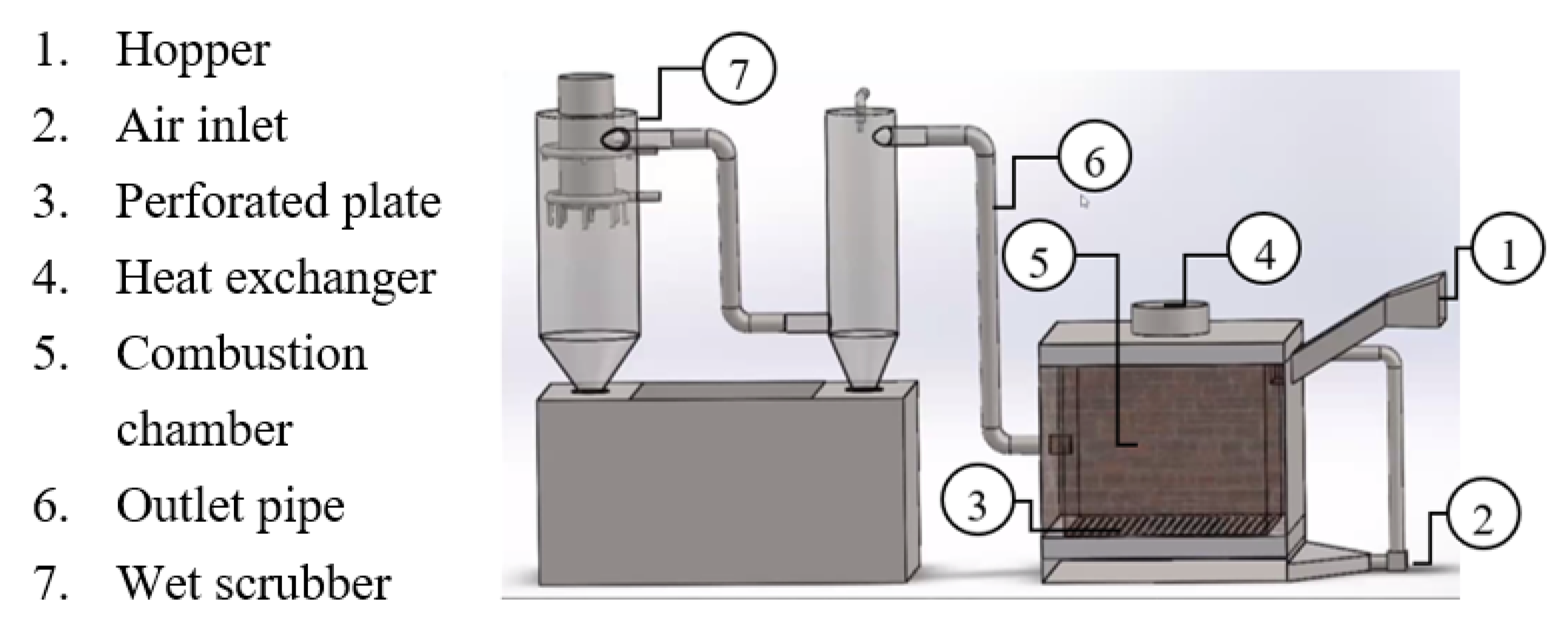
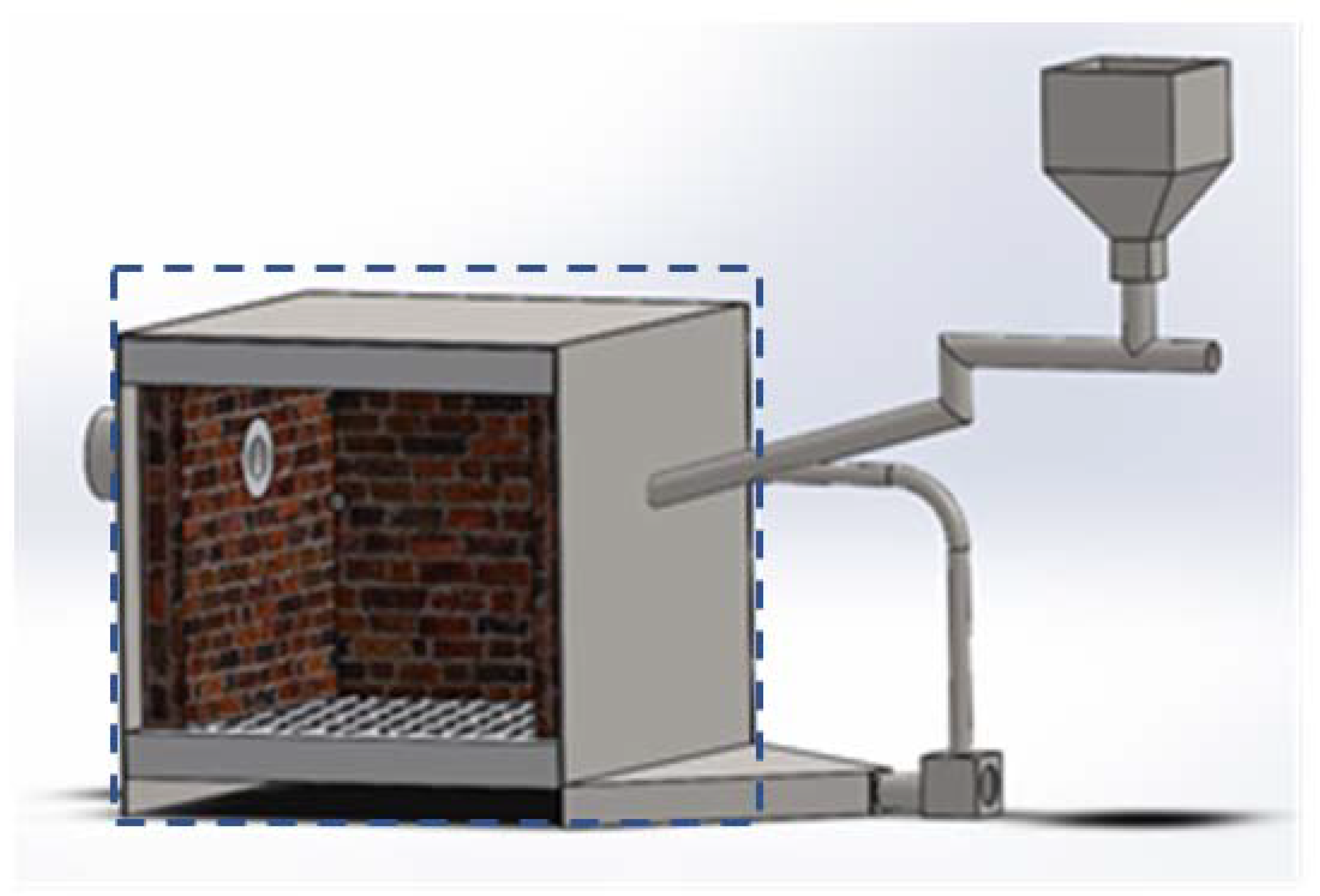
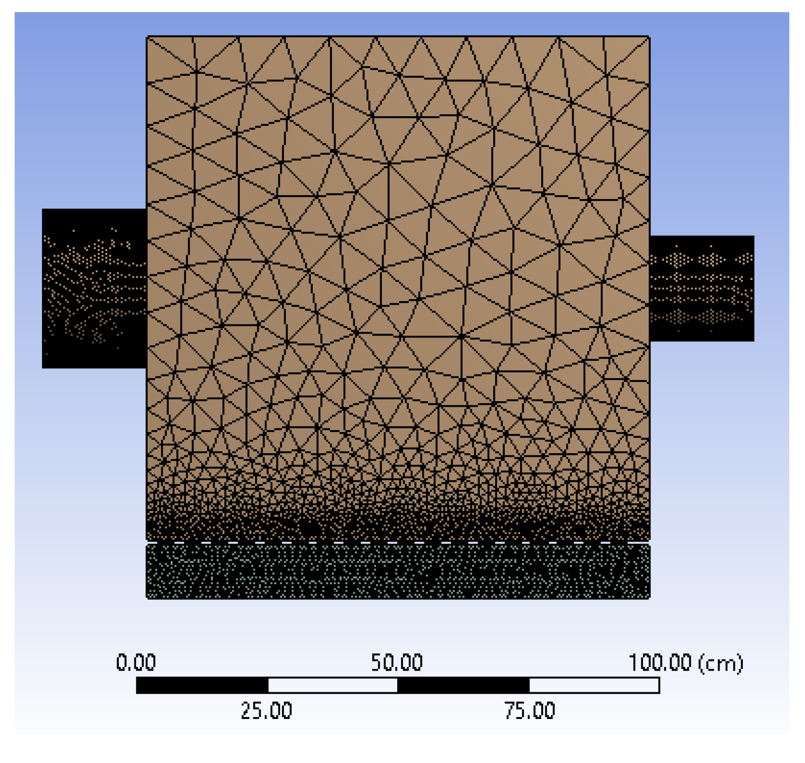
2. Materials and Methods

The main feedstocks were pellets produced from Calliandra trees. Table 1 contains a list of the proximate and ultimate analyses of biomass pellets. Pellets have a diameter of 7.5 mm, and a length of 15 mm. Pellets have a moisture content of 6.41%. Calliandra wood pellets have low amounts of fixed carbon and ash and have high oxygen content.
Figure 2 is a schematic representation of the experimental facilities that were developed in our lab. It is a furnace of the cubical type and measures around 1 m on each side, 1 m front to back, and 1 m in height, and it has a hopper and air intake in the front and output on the side opposite the hopper.
On the higher side, a hopper has been constructed, and on the lower side, there is an air inlet. As illustrated in Figure 3, air was drawn in from the intake, passed through the air plenum, and then delivered to the combustion chamber through a perforated plate with holes of 3 mm in diameter. Plates made of carbon steel were used in the construction of the combustion chamber. A fire brick with a thickness of 6.5 cm was laid down on the inside of the combustion chamber. There was space available at the very top of the combustion chamber, in the form of perforations, for a heat exchanger that could bring water to a boil.
The first step is to heat the furnace until it reaches a temperature of about 700 °C. Calliandra pellets were utilized at a mass flow rate of 75 kg/h. We utilized three different air fuel ratio (AFR) values: 5.7, 7.2, and 9.0. Each AFR modification was run three times, and the average was calculated. The flue gases were then transported via the wet scrubber and discharged out the facility exit. Three type K thermocouples were affixed to the inside wall of the combustion chamber: one at the bottom, one in the middle, and one at the top. The other thermocouple was attached to the burn chamber wall. Differences were present in the inner and outer wall temperatures, which can be used to ascertain how much heat is lost through the wall.
Due to the limits of commercial CFDs with respect to modelling large-scale solid combustion, the numerical research technique given here was based on a species model supplied by ANSYS FLUENT, and it was conducted by the simplification of inputs in the form of solids that have undergone devolatilization. The furnace’s domain, as shown in Figure 4, was subsequently discretized using the finite volume approach. The SIMPLE method was used to solve mass, momentum, and energy conservation equations. The standard k-epsilon formula was used to simulate turbulent events [25]. Radiative heat transfer was simulated using the P1 model. In this work, the combustion process was modeled as non-premixed combustion. The furnace composite wall, made of carbon steel plate and firebrick, was constructed as a wall with heat conductivity, specific heat, and density qualities that take advantage of its composite features. On the walls, heat losses have been estimated. The walls are subjected to convective boundary conditions with the surrounding air. The material parameters of composite walls are described such that the total resistance may be determined analogously to thermal resistance.
In steady-state conditions, Equations (1)–(3) show the equations for mass equilibrium, momentum equilibrium, the energy equation, and the species equation.
· ( ρ · v ) = S m
· ( ρ v v ) = p + · ( τ = ) + ρ g + F
[ v ( ρ E + p ) ] = v ( j h j J j ) + S h
where ρ denotes density, v denotes velocity, m indicates mass, and p is the static pressure. Moreover, τ = ,   ρ g , and F are a shear stress tensor, a gravitational effect, and an external force effect. J j is the species’ diffusion flow and h j is the species’ enthalpy. Meanwhile, S m   and S h denote sources of mass and energy obtained via reactions between the continuous and discrete phases.
In this work, non-premixed combustion modeling was utilized for the CFD simulation of Calliandra pellet combustion [26]. In this concept of non-premixed combustion, the fuel and oxidizer reach the combustion region via separate pathways. Using the probability density function (PDF) approach, we calculate the interplay between turbulence events and chemical processes. According to the findings of the ultimate and proximate analyses, the parameters of biomass were plugged into a coal calculator for this study. In the meantime, the P1 model was utilized to simulate the radiative heat transport, which differs from prior research that employed the DO model [25].
In general, this study employed a Eulerian–Lagrangian technique. As a transfer grid, a particle grid based on the fluid grid is utilized and a diffusion operation is employed to balance the gas phase and particle interactions. Interactions between gaseous and solid phases and radiative heat transmission between particles are considered [27]. The method used in this study is simpler than the one used in previous studies, which used the Eulerian–Lagrangian approach based on the coarse grain method (CGM) and the distribution kernel method (DKM), which group fuel and sand particles into parcels [28].
Figure 5 illustrates the usage of the tetrahedron approach for meshing. High levels of smoothness or smoothing have been achieved. Furthermore, no changes were made to the default settings. A denser mesh was built at the inlet, outlet, and hole in order to quantify the flow and heat transfer phenomena that occur in the vicinity of the inlet, outlet, and hole. Table 2 demonstrates the mesh quality. Due to the mesh’s continual influence on convergence and CFD results, great efforts were expended to obtain a high-quality, fine mesh.
Using an empirical formula, biomass fuels or pellets were represented as mixture fractions in this study. The empirical formula, C 8 , 7 H 12 , 5 O 6 , 4 , was generated using Table 1’s conclusive examination of biomass pellets. Utilizing the coal calculator tool, the percentage of each component, such as C, H, and O, was entered. An empirical formula was also applied when calculating the stoichiometric ratio of combustion. During the combustion procedure, the quantity of air was used as an input. The combustion process in biomass pellet furnaces was simulated using un-premixed combustion. This is because the fuel intake is distinct from the air intake. Fuel and air are employed in the combustion process within the combustion chamber. This combustion process was simulated using the probability density function (PDF) method and was caused by chemical interactions and turbulence. Before running the algorithm, initialize the initial values with standard values to facilitate convergence. Residual monitoring is a phase in the process of iteration that occurs until convergence is achieved. The default convergent value is 10−3 for all parameters. The energy and radiation residuals are 10−6.

3. Results and Discussion

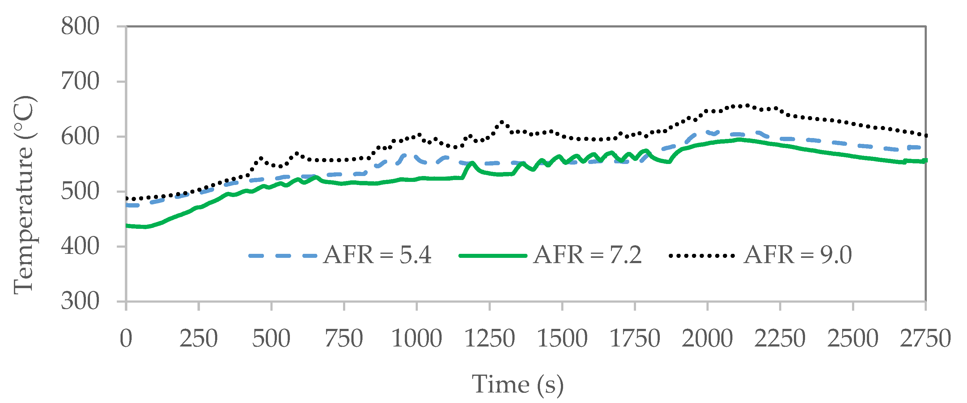
3.1. Combustion Temperature Profile

When air comes into contact with the biomass pellets at the bottom of the furnace, combustion begins. Consequently, the heat is transported to the output component by convection and radiation. Figure 6 and Figure 7 depict the average temperature profile at the top and bottom of the furnace vs time for various AFRs. Figure 6 depicts the combustion gas temperature of the top furnace as being between 430 and 650 °C, while Figure 7 depicts the combustion gas temperature of the bottom furnace as being between 440 and 700 °C. The combustion chamber’s combustion gas temperature varies from 400 to 750 degrees Celsius, which is comparable with earlier research on the combustion testing of various types of biomass pellets [29]. When there is no discernible temperature difference between the top and bottom of a furnace, the heat generated by combustion is evenly distributed throughout the chamber.
From 0 to 500 s, the combustion chamber temperature rises due to the steady introduction of biomass pellets. In a combustion furnace, biomass pellets undergo several processes, including drying, devolatilization, volatile combustion, charcoal combustion, and ash generation. The combustion of volatiles is more rapid than combustion of char [30]. Consequently, during the 1000 s to 2250 s combustion phase, the temperature increase at the top of the furnace is somewhat faster than the temperature increases at the bottom of the furnace. After 2250 s, the supply of biomass pellets was cut off, which caused the temperature to plummet.
In biomass combustion, devolatilization is a vital stage. During the devolatilization process, the majority of the biomass with a high volatile content is liberated from the particles. Particles may grow or shrink depending on the type of biomass. The devolatilization process, on the other hand, is likely to produce an acceleration of combustion gases. Rocketing phenomena due to abrupt acceleration during the combustion process of volatiles have been studied utilizing devolatilization kinetic parameters [31].
The temperature profile of the combustion gas between 2250 s and 2750 s demonstrates an overall cooling tendency. The furnace cools when the fuel source is interrupted. Even in the absence of fuel, the blowers continue to operate. Consequently, there is a surplus of air relative to what is necessary for combustion. As air is blown out of the exhaust, it carries away a portion of the heat from the combustion process, causing the chamber to cool [22]. Moreover, volatile gas and fuel char emissions are affected by the high rate of air supply for combustion [32]. When the air supply rate hits a particular threshold, volatile gas emissions and the amount of combustion char increase. If the airflow rate is raised further, the combustion process might be delayed. As a result, the composition of the volatile gases and char being burnt affects the gas temperatures in the combustion chamber.
Furthermore, due to the low ash content of Calliandra pellets (1.12%) and the low Si and K contents of wood biomass, which differ from those of agricultural wastes, the melt potential is similarly limited. Using SiP/CaMg, SiPNaK/B, or NaK/B ratios higher than 0.5, the slag potential of molten ash may be anticipated [33]. Biomass pellets with high slag potentials are not approved for large furnaces above 100 kW [34]. A previous study indicated that when biomass pellet ash was subjected to heat at 1000 °C, it entirely melted [34]. In actuality, the temperature of the furnace created for this investigation is still below 1000 °C, so ash melting is quite improbable. The handling of bottom ash occurs in the presence of a distributor that also works as a grate, and the periodic removal of bottom ash from the grate occurs when the performance of the perforated plate declines, which is defined by a drop in the temperature of the burning gas.

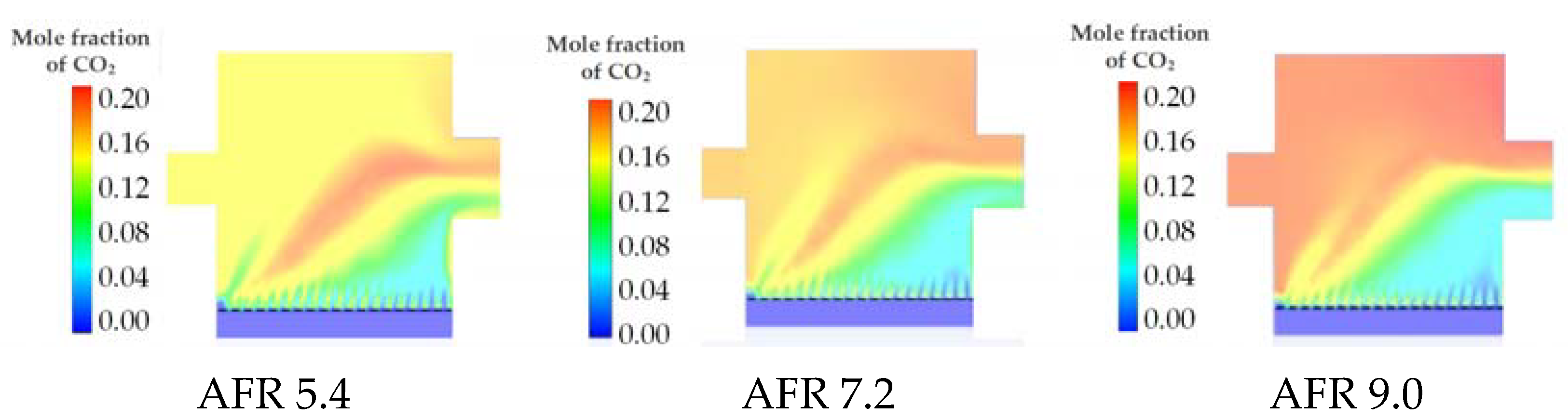
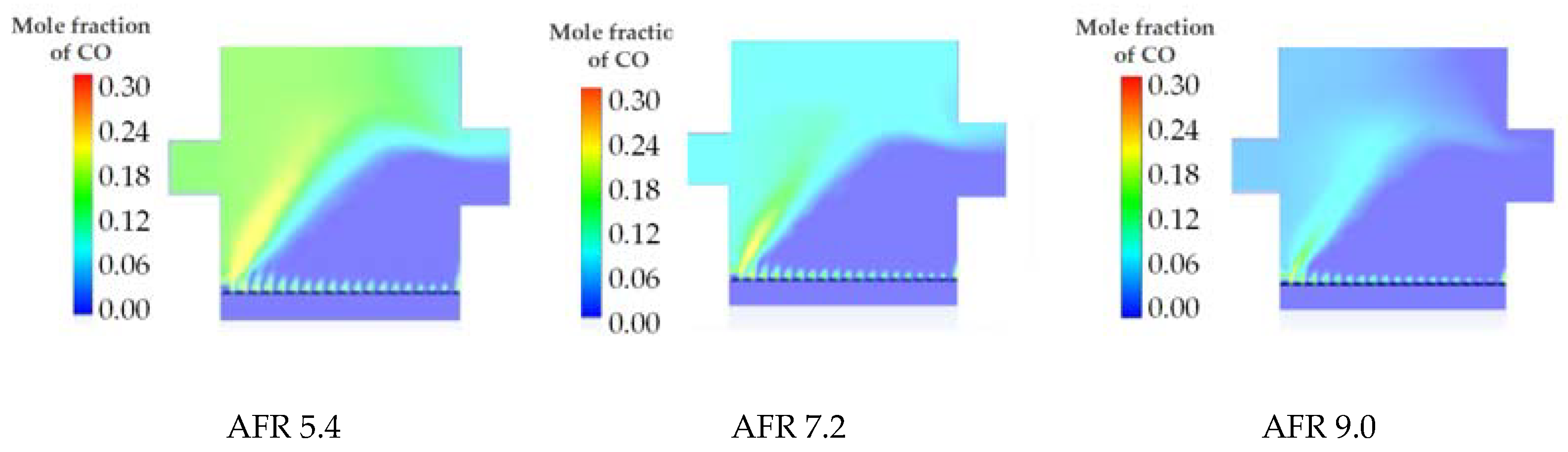
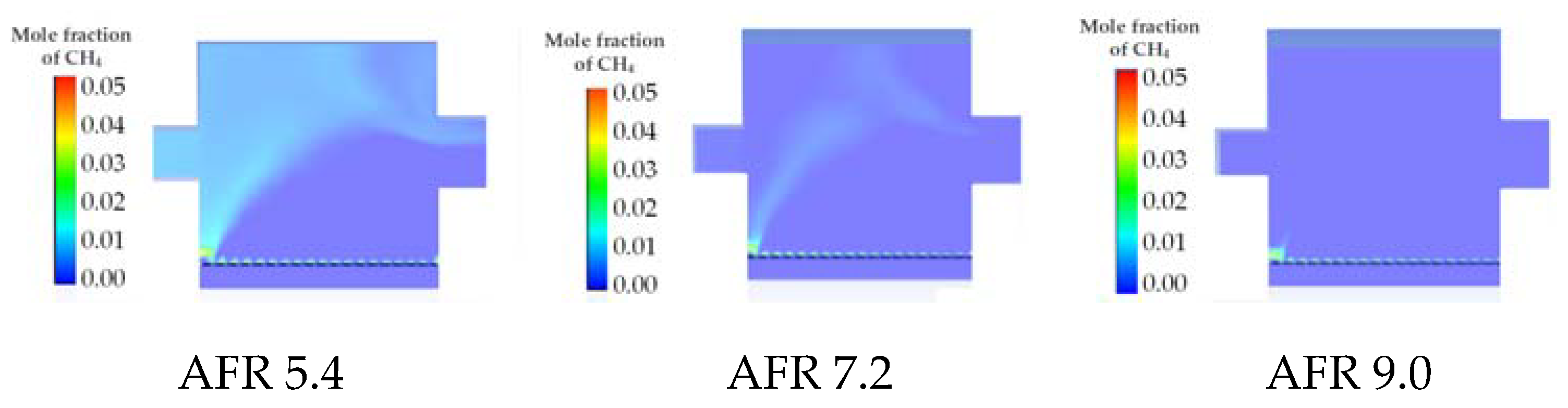
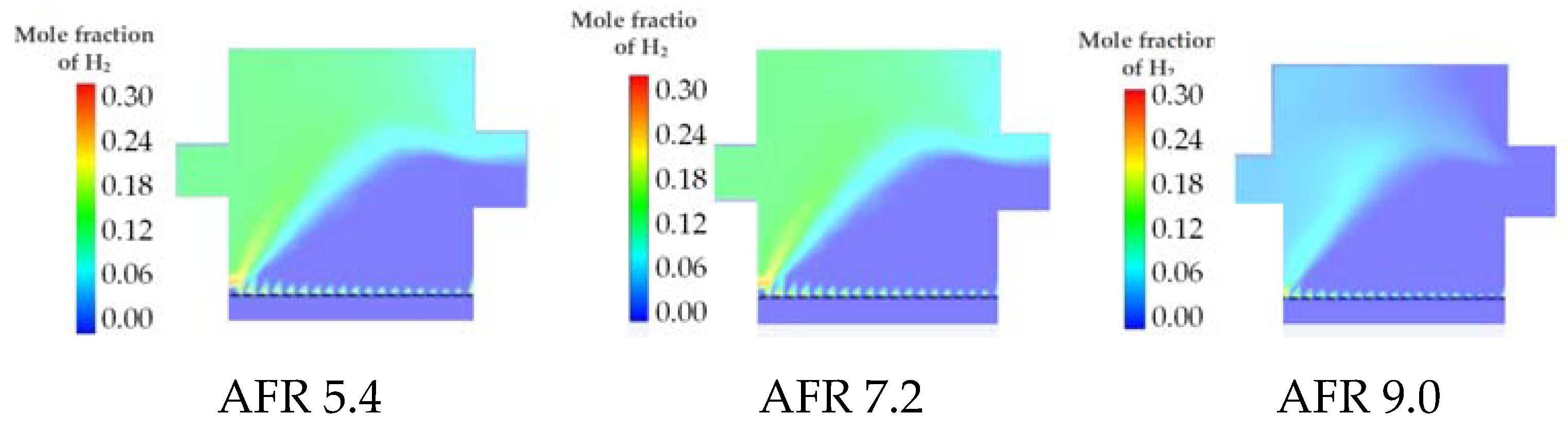
3.2. Gas Composition and Distribution

Using air–fuel ratios (AFRs) of 5.4, 7.2, and 9.0, numerical simulations have been performed to determine the combustion efficiency of biomass pellets in these furnaces. The numerical simulation temperature in the furnace is within 5.2% of the experimental temperature, as shown in Table 3.
It has been demonstrated that the combustion gas’s bottom temperature falls as the AFR rises. From 928 K, the temperature dropped to 907 K, then to 945 K. The combustion gas temperature will fall when there is an excessive amount of air surrounding the flame. As the AFR rose to intermediate and high levels, the combustion gas temperature increased. The temperature rose from 927 K to 945 K in the middle. In contrast, temperatures of 881 K, 860 K, and 919 K were observed at higher AFR levels. As a result of adding additional air to the chamber’s upper and central portions, the combustion rate increases.
From what can be observed in Figure 8, when the AFR was raised, the velocity of the combustion gas being emitted increased. Maximum speeds increased from 8.9 m/s at an AFR of 5.4 to 11 m/s and 12.9 m/s with an AFR of 7.2 to 9.0.
Figure 9 indicates that when the AFR rises, the gas velocity in the region above the perforated plate increases by more than 1.5 m/s. When the air velocity increased above the perforated plate, air and fuel were perhaps carried to the center of the combustion chamber. As demonstrated in Figure 10, with an air-to-fuel ratio of 9.0, oxygen may reach the middle of the combustion chamber. However, as the AFR increased, so did the amount of oxygen that was not burned. This was shown by the yellowing of the exhaust gas contours.
The burning of biomass pellets with air would create carbon dioxide, H2O, and N2. Figure 11 illustrates that when the AFR increases, the concentration of CO2 in the combustion chamber rises to about 18%. Figure 12 illustrates that as the AFR increased, so did the quantity of H2O found in the combustion chamber, reaching a peak of around 13.4%.
Figure 13, Figure 14 and Figure 15 show the concentrations of CO, CH4, and H2 gases in the combustion gases at AFRs of 5.4, 7.2, and 9.0. The presence of these three gases indicated that the combustion process was incomplete. The existence of CO gas shows that a partial oxidation process of C + ½ O2 → CO occurred. The increasing number of the AFR resulted in a reduced CO gas concentration in the outputs, indicating that the furnace’s combustion quality had improved. A prior investigation of biomass combustion with fluctuations in extra air found a similar result [35].
Due to of the reaction of C + 2H2 → CH4, the existence of CH4 gas was conceivable. Whereas the reaction of C + H2O CO + H2 might result in the formation of H2 gas. The higher the AFR, the lower the CO, CH4, and H2 gas concentrations. Similarly, when the AFR climbed, the CO, CH4, and H2 gas concentrations decreased.
A higher AFR increases the combustion quality significantly. The greater the amount of air that can reach the Calliandra pellets, the more intense the combustion, lowering the unburned fuel and the likelihood of partial oxidation. This is consistent with prior research results, which revealed an increase in the combustion of volatile gases and char, as well as an increase in the combustion air supply [32]. Increases in the AFR, on the other hand, increase the flow of oxygen out of the furnace. Table 4 shows that even at an air-to-fuel ratio of 9.0, there is still 8.29% oxygen present, showing that the air dispersion in this furnace design is not optimal.

3.3. Energy Distribution

The combustion of Calliandra wood pellets in a furnace generates heat energy. The recommended feeding rate of 75 kg/h may offer an energy input of 326 kJ/s. During the testing procedure, a large quantity of energy was created on the output side, and part of it was lost via heat loss. All components of the furnace that allowed heat to escape were analyzed with respect to their heat loss characteristics. The amount of heat loss accounted for in each AFR measurement varies considerably. According to Table 5, the larger the AFR value, the greater the estimated heat losses.
The increase in the AFR in places with poor mixing does not significantly enhance the amount of energy delivered to the combustion product. As stated in Table 5, the furnace outlet of an AFR of 5.4 generated 272.23 kW of energy. Using an AFR of 7.2 and an AFR of 9.0 results in a total heat transfer of 273.51 kW and 275.56 kW, respectively. Consequently, our study demonstrates that the energy output of these furnaces is nearly consistent and varies between 270 and 275 kW throughout a variety of AFR tests. Similar quantities of energy were lost via the furnace wall, ranging from 29 to 37 kW, or approximately 8–11%. The furnace efficiency varies between 82 and 89%, with AFRs between 5.4 and 9.0, which are much higher than the 68% seen in a previous study [15]. These findings show that the furnace’s design is fairly excellent and successful in generating energy, with a capacity of more than 200 kW utilizing dimensions of 1 m × 1 m × 1 m and a perforated plate.

4. Conclusions

The 200 kW combustion furnace for Calliandra wood pellets has been successfully designed and tested with respect to its performance and emissions. According to the results of the tests and simulations, increasing the AFR has no major effect on the furnace’s efficiency. For AFRs between 5.4 and 9.0, the furnace efficiencies range between 82% and 89%. The composition and rate of the combustion gas were successfully tested, proving that the furnace could ideally burn Calliandra pellets. So, our study shows that the energy output of these furnaces is almost always between 270 and 275 kW, even when they are put through different AFR tests. The oxygen flow distribution, on the other hand, does not appear to be very uniform throughout the furnace, indicating that adjustments to the design of the intake and exit air distribution remain possibilities for enhanced furnace performance. Some of these can be accomplished by increasing the diameter and composition of the distributor hole. Another method is to separate the air into main and secondary air. Some of these approaches can be studied further numerically as well as experimentally.

Author Contributions

Conceptualization, S. and M.M.; methodology, H.S. and T.G.N.; software, T.G.N. and S.; validation, H.S. and M.M.; formal analysis, S., H.S. and T.G.N.; investigation, H.S.; writing, S., T.G.N., H.S. and M.M. All authors have read and agreed to the published version of the manuscript.

Funding

This research was funded by PU-UNS (260/UN27.22/HK.07.00/2021) and PTUPT BRIN (054/E5/PG.02.00.PT/2022 and 469.1/UN27.22/PT.01.03/2022).

Data Availability Statement

Not applicable.

Acknowledgments

The authors would like to thank the Rector of Sebelas Maret University for the financial support provided by RKAT PTNBH Universitas Sebelas Maret under the Excellent Research Scheme of PU-UNS, which was partially supported by PTUPT research grants. Sunu Pranolo from Sebelas Maret University’s Department of Chemical Engineering should be praised for giving permission to use the licensed ANSYS FLUENT software.

Conflicts of Interest

The authors declare no conflict of interest.

References

  1. Hu, Q.; Shao, J.; Yang, H.; Yao, D.; Wang, X.; Chen, H. Effects of Binders on the Properties of Bio-Char Pellets. Appl. Energy 2015, 157, 508–516. [Google Scholar] [CrossRef]
  2. Simões Amaral, S.; Andrade de Carvalho, J., Jr.; Martins Costa, M.A.; Pinheiro, C. Particulate Matter Emission Factors for Biomass Combustion. Atmosphere 2016, 7, 141. [Google Scholar] [CrossRef] [Green Version]
  3. Nunes, L.J.R.; Matias, J.C.O.; Catalão, J.P.S. Mixed Biomass Pellets for Thermal Energy Production: A Review of Combustion Models. Appl. Energy 2014, 127, 135–140. [Google Scholar] [CrossRef]
  4. Karkania, V.; Fanara, E.; Zabaniotou, A. Review of Sustainable Biomass Pellets Production–A Study for Agricultural Residues Pellets’ Market in Greece. Renew. Sustain. Energy Rev. 2012, 16, 1426–1436. [Google Scholar] [CrossRef]
  5. Sjoding, D.; Kanoa, E.; Jensen, P. Developing a Wood Pellet/Densified Biomass Industry in Washington State: Opportunities and Challenges; Technical Assessment: Washington, DC, USA, 2013. [Google Scholar]
  6. Rosyadi, I.; Suyitno, S.; Ilyas, A.X.; Faishal, A.; Budiono, A.; Yusuf, M. Producing Hydrogen-Rich Syngas via Microwave Heating and Co-Gasification: A Systematic Review. Biofuel Res. J. 2022, 9, 1573–1591. [Google Scholar] [CrossRef]
  7. Gravitiani, E.; Arifin, Z.; Muqoffa, M.; Hadi, S. Feasibility of Electric Generation from Municipal Solid Wastes by Incineration and Gasification. In Proceedings of the 6th International Conference and Exhibition on Sustainable Energy and Advanced Materials, Surakarta, Indonesia, 16–17 October 2019; Springer: Berlin/Heidelberg, Germany, 2020; pp. 485–491. [Google Scholar]
  8. Boman, C.; Pettersson, E.; Westerholm, R.; Boström, D.; Nordin, A. Stove Performance and Emission Characteristics in Residential Wood Log and Pellet Combustion, Part 1: Pellet Stoves. Energy Fuels 2011, 25, 307–314. [Google Scholar] [CrossRef]
  9. Sippula, O.; Hytönen, K.; Tissari, J.; Raunemaa, T.; Jokiniemi, J. Effect of Wood Fuel on the Emissions from a Top-Feed Pellet Stove. Energy Fuels 2007, 21, 1151–1160. [Google Scholar] [CrossRef]
  10. Ryu, C.; Yang, Y.B.; Khor, A.; Yates, N.E.; Sharifi, V.N.; Swithenbank, J. Effect of Fuel Properties on Biomass Combustion: Part I. Experiments—Fuel Type, Equivalence Ratio and Particle Size. Fuel 2006, 85, 1039–1046. [Google Scholar] [CrossRef]
  11. Rhén, C.; Öhman, M.; Gref, R.; Wästerlund, I. Effect of Raw Material Composition in Woody Biomass Pellets on Combustion Characteristics. Biomass Bioenergy 2007, 31, 66–72. [Google Scholar] [CrossRef]
  12. Biswas, A.K.; Rudolfsson, M.; Broström, M.; Umeki, K. Effect of Pelletizing Conditions on Combustion Behaviour of Single Wood Pellet. Appl. Energy 2014, 119, 79–84. [Google Scholar] [CrossRef]
  13. Ahn, J.; Kim, J.J. Combustion and Heat Transfer Characteristics inside the Combustion Chamber of a Wood Pellet Boiler. J. Mech. Sci. Technol. 2014, 28, 789–795. [Google Scholar] [CrossRef]
  14. Marigo, M.; Zulli, F.; Bordignon, S.; Carnieletto, L.; Emmi, G.; De Carli, M. Energy Analysis of a Wood or Pellet Stove in a Single-Family House Equipped with Gas Boiler and Radiators. Build. Simul. 2022, 15, 1577–1593. [Google Scholar] [CrossRef]
  15. Greinert, A.; Mrówczyńska, M.; Grech, R.; Szefner, W. The Use of Plant Biomass Pellets for Energy Production by Combustion in Dedicated Furnaces. Energies 2020, 13, 463. [Google Scholar] [CrossRef] [Green Version]
  16. Orjala, M. Burner for Pellets. U.S. Patent 4515088, 7 May 1985. [Google Scholar]
  17. Zempel, A.M. System for Burning Biomass Pellets. U.S. Patent 4454828, 19 June 1984. [Google Scholar]
  18. Klason, T.; Bai, X.S. Computational Study of the Combustion Process and NO Formation in a Small-Scale Wood Pellet Furnace. Fuel 2007, 86, 1465–1474. [Google Scholar] [CrossRef]
  19. Lee, Y.-W.; Ryu, C.; Lee, W.-J.; Park, Y.-K. Assessment of Wood Pellet Combustion in a Domestic Stove. J. Mater. Cycles Waste Manag. 2011, 13, 165–172. [Google Scholar] [CrossRef]
  20. Kshirsagar, M.P.; Kalamkar, V.R. Application of Multi-Response Robust Parameter Design for Performance Optimization of a Hybrid Draft Biomass Cook Stove. Renew. Energy 2020, 153, 1127–1139. [Google Scholar] [CrossRef]
  21. Shimizu, T.; Han, J.; Choi, S.; Kim, L.; Kim, H. Fluidized-Bed Combustion Characteristics of Cedar Pellets by Using an Alternative Bed Material. Energy Fuels 2006, 20, 2737–2742. [Google Scholar] [CrossRef]
  22. Roy, M.M.; Dutta, A.; Corscadden, K. An Experimental Study of Combustion and Emissions of Biomass Pellets in a Prototype Pellet Furnace. Appl. Energy 2013, 108, 298–307. [Google Scholar] [CrossRef]
  23. Ahn, J.; Jang, J.H. Combustion Characteristics of a 16 Step Grate-Firing Wood Pellet Boiler. Renew. Energy 2018, 129, 678–685. [Google Scholar] [CrossRef]
  24. Jetter, J.J.; Kariher, P. Solid-Fuel Household Cook Stoves: Characterization of Performance and Emissions. Biomass Bioenergy 2009, 33, 294–305. [Google Scholar] [CrossRef]
  25. Zadravec, T.; Rajh, B.; Kokalj, F.; Samec, N. The Impact of Secondary Air Boundary Conditions on CFD Results in Small-Scale Wood Pellet Combustion. Fuel 2022, 324, 124451. [Google Scholar] [CrossRef]
  26. Hafiz, M.; Nelwan, L.O.; Yulianto, M. CFD-Based Analysis of Non-Premixed Combustion Model in Biomass Grate Furnaces. In Proceedings of the IOP Conference Series: Earth and Environmental Science, Bogor, Indonesia, 23–25 October 2017; IOP Publishing: Bristol, UK, 2018; Volume 147, p. 12029. [Google Scholar]
  27. Zhang, J.; Li, T.; Ström, H.; Løvås, T. Computationally Efficient Coarse-Graining XDEM/CFD Modeling of Fixed-Bed Combustion of Biomass. Combust. Flame 2022, 238, 111876. [Google Scholar] [CrossRef]
  28. Yang, M.; Zhang, J.; Zhong, S.; Li, T.; Løvås, T.; Fatehi, H.; Bai, X.-S. CFD Modeling of Biomass Combustion and Gasification in Fluidized Bed Reactors Using a Distribution Kernel Method. Combust. Flame 2022, 236, 111744. [Google Scholar] [CrossRef]
  29. Kallis, K.X.; Susini, G.A.P.; Oakey, J.E. A Comparison between Miscanthus and Bioethanol Waste Pellets and Their Performance in a Downdraft Gasifier. Appl. Energy 2013, 101, 333–340. [Google Scholar] [CrossRef]
  30. Glassman, I.; Yetter, R.A.; Glumac, N.G. Combustion of Nonvolatile Fuels. Combustion 2015, 4, 495–550. [Google Scholar]
  31. Llamas, Á.D.G.; Guo, N.; Li, T.; Gebart, R.; Umeki, K. Rapid Change of Particle Velocity Due to Volatile Gas Release during Biomass Devolatilization. Combust. Flame 2022, 238, 111898. [Google Scholar] [CrossRef]
  32. Yang, Y.B.; Sharifi, V.N.; Swithenbank, J. Effect of Air Flow Rate and Fuel Moisture on the Burning Behaviours of Biomass and Simulated Municipal Solid Wastes in Packed Beds. Fuel 2004, 83, 1553–1562. [Google Scholar] [CrossRef]
  33. Contreras-Trejo, J.C.; Vega-Nieva, D.J.; Heya, M.N.; Prieto-Ruíz, J.A.; Nava-Berúmen, C.A.; Carrillo-Parra, A. Sintering and Fusibility Risks of Pellet Ash from Different Sources at Different Combustion Temperatures. Energies 2022, 15, 5026. [Google Scholar] [CrossRef]
  34. Kuptz, D.; Kuchler, C.; Rist, E.; Eickenscheidt, T.; Mack, R.; Schön, C.; Drösler, M.; Hartmann, H. Combustion Behaviour and Slagging Tendencies of Pure, Blended and Kaolin Additivated Biomass Pellets from Fen Paludicultures in Two Small-Scale Boilers < 30 KW. Biomass Bioenergy 2022, 164, 106532. [Google Scholar] [CrossRef]
  35. Youssef, M.A.; Wahid, S.S.; Mohamed, M.A.; Askalany, A.A. Experimental Study on Egyptian Biomass Combustion in Circulating Fluidized Bed. Appl. Energy 2009, 86, 2644–2650. [Google Scholar] [CrossRef]
Figure 1. Keywords utilized in the study: (a) wood pellet, (b) wood pellet combustion analyzed using ScientoPy.
Energies 15 08251 g001
Figure 2. Experimental scheme for a biomass pellet furnace.
Energies 15 08251 g002
Figure 3. Perforated plate.
Energies 15 08251 g003
Figure 4. Thermodynamic system and domain simulated in ANSYS FLUENT.
Energies 15 08251 g004
Figure 5. Meshing of the domain.
Energies 15 08251 g005
Figure 6. Trends in combustion chamber temperature on the upper side as determined by experiment.
Energies 15 08251 g006
Figure 7. Trends in combustion chamber temperature on the lower side as determined by experiment.
Energies 15 08251 g007
Figure 8. Combustion gas speed.
Energies 15 08251 g008aEnergies 15 08251 g008b
Figure 9. Speed of combustion gas at perforated plate.
Energies 15 08251 g009
Figure 10. Contours of O2 concentration.
Energies 15 08251 g010
Figure 11. Contours of CO2 concentration.
Energies 15 08251 g011
Figure 12. Contours of H2O concentration.
Energies 15 08251 g012
Figure 13. Contours of CO concentration.
Energies 15 08251 g013
Figure 14. Contours of CH4 concentration.
Energies 15 08251 g014
Figure 15. Contours of H2 concentration.
Energies 15 08251 g015
Table 1. Proximate and ultimate analysis of wood pellet.
ParametersUnitBasisResults
Proximate Analysis
Total moisture%ar6.41
Volatile matter%adb77.82
Total Sulphur%adb0.06
Ash content%adb1.12
Gross calorific valueMJ/kgadb18.17
Net calorific valueMJ/kgadb16.79
Chlorine (Cl)ppmadb498.75
Ultimate Analysis
Carbon%adb46.80
Hydrogen%adb5.61
Nitrogen%adb0.26
Oxygen by difference%adb47.33
adb = air dried basis; ar = as received.
Table 2. Quality of mesh design geometry.
Aspect RatioSkewnessOrthogonal Quality
MaxMinAverageMaxMinAverageMaxMinAverage
9.311.161.860.801.72 × 10−40.240.990.200.76
Table 3. Temperature comparison between experiments with numerical simulations.
LocationTemperature (K)Deviation (%)Average
SimulationExperiment(%)
AFR 5.4
Top8648811.935.2
Middle8649276.80
Bottom8649286.90
AFR 7.2
Top8758601.743.22
Middle8759073.52
Bottom9479074.41
AFR 9.0
Top8799194.353.99
Middle8799456.98
Bottom9519450.63
Table 4. Biomass pellet combustion gas components.
No.Gas TypeAFR 5.4AFR 7.2AFR 9.0
1N267.1970.3572.37
2O23.456.138.29
3CO2.501.070.23
4H22.310.850.14
5H2O9.918.957.92
6CO214.5612.6411.05
7CH40.070.010.00
TOTAL100100100
Table 5. Energy analysis of the furnace.
DomainTotal Heat Transfer (kW)
SimulationExperiment
AFR =
5.4
AFR =
7.2
AFR =
9.0
AFR =
5.4
AFR =
7.2
AFR =
9.0
Outlet272.23273.51275.56270.97270.58275.24
Wall−29.83−31.02−29.90−36.40−34.01−37.70
Total242.40242.49245.66234.57236.57237.54
Publisher’s Note: MDPI stays neutral with regard to jurisdictional claims in published maps and institutional affiliations.

