Review

Overview of Integrated Electric Motor Drives: Opportunities and Challenges

School of Energy and Environment, City University of Hong Kong, Hong Kong, China
*
Author to whom correspondence should be addressed.
Energies 2022, 15(21), 8299; https://doi.org/10.3390/en15218299
Submission received: 8 October 2022 / Revised: 31 October 2022 / Accepted: 2 November 2022 / Published: 7 November 2022

Abstract

:
Integrated Motor Drives (IMDs) have recently received extensive attention. In electric vehicles (EVs), electric propulsion aircraft, and ship propulsion systems, integrated motors have the great potential to replace traditional motors with the distinct merits of compact size, high power density, high efficiency, and high-cost effectiveness. This paper investigates and reviews integrated motor drives’ development and critical technologies. It not only reveals the research progress of the motor structure, converter, volume optimization, heat dissipation design, and weakening electromagnetic interference of integrated motor drives but also explores in detail the applications of wide-bandgap semiconductors and the integration of LCL filters. In addition, this paper also puts forward the concept of integrated motor drive integration level and establishes a corresponding quantitative method to evaluate IMDs integration level. In the future, integrated wireless motor drives will have a broad scope of research and application. IMDs systems will play an important role in applications requiring high power density, providing solutions to motor system size and heat dissipation problems. This overview will help clarify the opportunities, challenges, and future development of IMDs.

1. Introduction

Electric motors with high power density and low bulk weight have drawn much attention recently with the development of electric propulsion systems for electric automobiles and aircraft [1,2,3]. In conventional motor propulsion systems, cables are typically used to connect the motors, power converters, controllers, and sensors [4,5]. Due to the separated design, the motor system is heavier and more prominent, and the cable connections cause issues, including extra losses and electromagnetic interference [6]. It significantly hampered the continued advancement and use of electric motors in aviation and electric automobiles [7,8]. The idea of integrated motors was consequently suggested in the 1990s [9].
Integrated motor drives combine the motor and its corresponding converter and control equipment with the motor, eliminating the need for additional control equipment when used. Thanks to this integrated design, the converter and controller housing take up less space, and there is no longer a need for lengthy connections to link the motor and converter, which can result in cost savings of between 20% and 40% [10]. Compared to conventional motors, IMDs will have lower system losses due to the reduced application of cables. In addition, the current IMDs will design converters for the internal space of the motor to realize the combination of drive and motor. This combination will not increase the motor’s size, so the system’s overall size will be significantly optimized compared to conventional motors. In traditional motors, the diameter of the cable is usually not negligible due to the high current. The weight of the connection cable of a conventional motor is not large. Therefore, reducing the size of the converter DC-link capacitors and lines will also reduce the importance of the IMDs. Optimizing the size and weight for the same power will lead to an increase in system power density. Such optimization is valuable for motor systems in applications with high power density requirements.
Integrated motor drive development can be broken down into three major stages. The inverter was housed in a separate converter box for the early integrated motors, which was connected to the top of the motor by a unique connection plate [11], such as the Siemens CombiMaster FSA motor and SEW-Movimot Eurodrive’s motor [12]. However, this IMDs design combines the motor and the converter without considering the structural design of the motor from the whole system perspective. As a result, the volume optimization of the motor is limited [8].
Since the converter and controller are integrated into the motor housing in the second generation of IMDs, the motor’s size is kept constant, and the benefits of an integrated motor become apparent. The second-generation IMDs mount the converter on the end plate or stator surface, allowing it to share a heat sink with the motor and remain entirely inside the confines of the motor housing [13]. However, this approach could make the motor design much more difficult. As the converter’s heat generation and electromagnetic impacts must be considered during setup, the system’s overall thermal layout, vibration resistance, and EMI resistance must be coordinated [14,15]. Additionally, because second-generation IMDs are currently frequently customized and it is challenging to employ standardized motor and converter components, this higher level of integration increases manufacturing costs [16]. However, the cost will still decrease when the system is finally implemented. Manufacturers are also worried about this aspect.
Thus, the third generation of IMDs features a modular design philosophy. The third-generation IMD is made up of several modular components. Each modular unit comprises a single motor stator pole, the matching converter, and the controller. The Integrated Modular Motor Drive (IMMD) is the common name for this design [17]. The modular architecture reduces manufacturing and design costs by facilitating manufacture and assembly and enabling a more comprehensive supply chain [18]. As shown in Table 1 [10], integrated motor drives provide benefits, including higher stability, lower losses, lower costs, and higher power density.
The first generation of IMDs is a simple combination of motor and drive, with the drives located outside the motor housing [10]. Therefore, it did not increase the difficulty and cost of maintenance compared to conventional motors during servicing. However, the second generation of IMDs integrates the drive inside the motor to achieve a truly integrated design. While this integrated design reduces the size of the system, it also raises the issue of higher maintenance costs. Because the driver is located inside the motor, IMDs must be disassembled when the driver or any part of the motor fails. The complex structure of the IMDs themselves will undoubtedly lead to higher maintenance costs. However, IMMDs are designed in a modular way. When a failure occurs, the faulty module can be disassembled. This modular design can reduce maintenance difficulties and repair costs.
However, there are still constraints on developing integrated motor drives [13,19], for example:
(1)
The thermal coupling of the motor and converter poses new challenges for system heat dissipation.
(2)
The influence of the size of the DC-link capacitor. Excessive DC-link capacitance increases the system size and poses vibration problems.
(3)
The design of the IMMDs structure requires careful consideration of the effects of various complex factors.
(4)
The IMMDs system requires the selection of a suitable converter to reduce the capacitance volume and achieve better control.
(5)
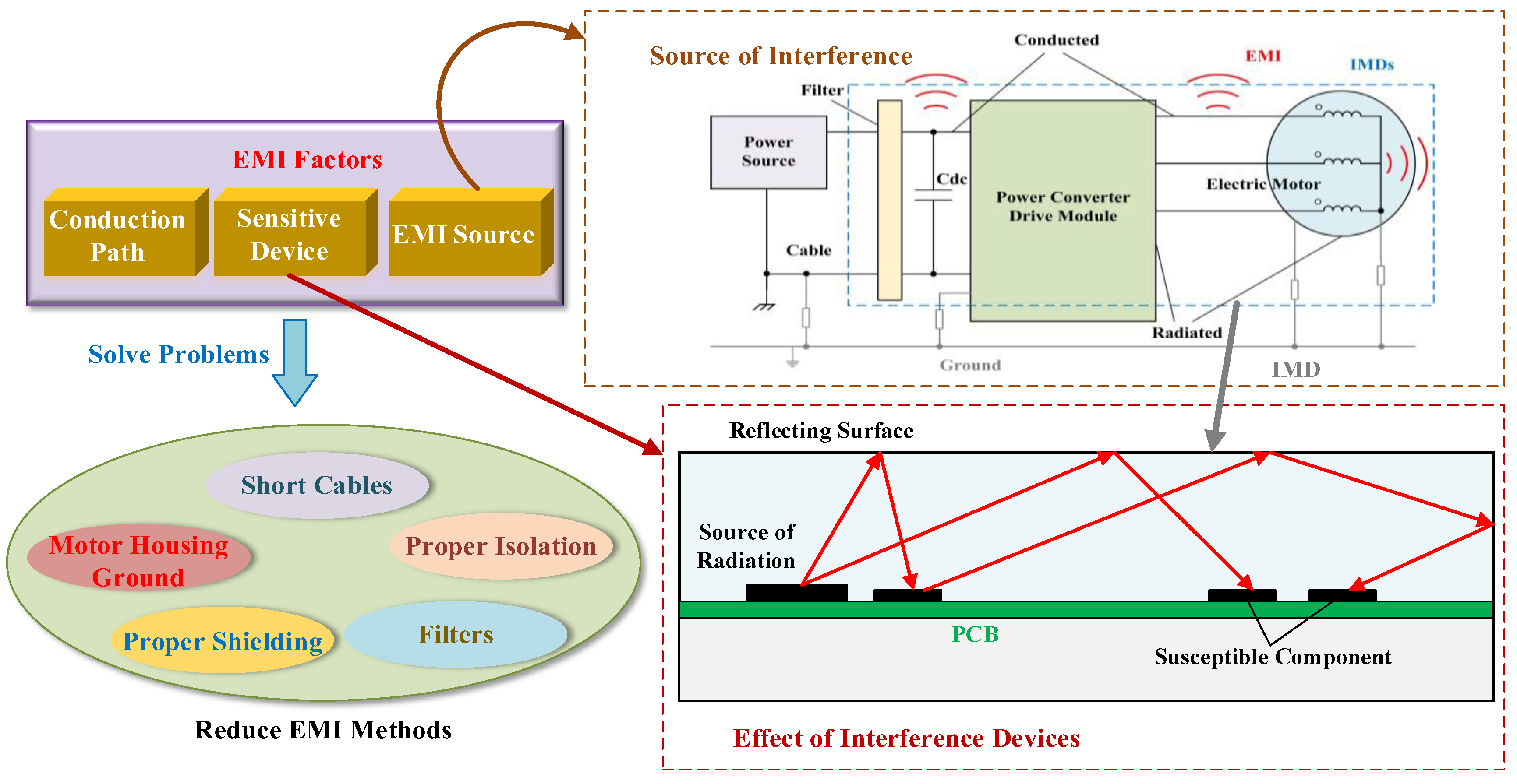
Electromagnetic interference (EMI) issues between the converter and the motor.
These issues are also currently being investigated by researchers. The relevant researchers have proposed constructive solutions to some of these problems, which will be discussed in later chapters. Due to the advantages of small size, high power density, and low losses of integrated motor drives, the research, and application of IMDs have a very high academic value. In this paper, we review the current development status of IMDs and provide various research directions for the development of IMDs. This paper provides an overview of the integrated motor drives’ structure, converter, DC-link capacitor, and thermal and EMI design. Further applications of IMDs are described, and trends and outlooks for IMDs are given.
Section 2 reviews the development, structure, and classification of IMDs. Section 3 reviews volume optimization and LCL filter integration techniques for IMDs converters. Section 4 reviews thermal and EMI design for IMDs. Section 5 provides opportunities and challenges for IMDs.

2. Integrated Motor Drive Structure Design

2.1. IMDs Development

The introduction noted that the creation of IMDs can be roughly separated into three steps. IMDs were optimized toward compactness, global design, and adaptability to meet the current requirement for high energy density, low cost, and low volume and weight consumption [6]. Table 2 contains the models and details on a few integrated motors [20,21,22,23,24,25,26,27,28,29,30,31,32,33]. Table 2 shows that the early integrated motor drives had relatively modest power ratings, frequently under 7.5 kW. This is because early IMDs connected the converter box to the motor housing and did not consider the motor’s global structure regarding heat dissipation, vibration, and electromagnetic compatibility. Joint simulations of several physical fields have been undertaken in IMDs design with finite element analysis (FEA) tools as the integration level of IMDs has grown [34,35,36]. In addition, converters can handle more significant currents because of heat dissipation designs made especially for IMDs, which significantly raises the IMDs power ratings [37]. The more traditional integrated motor drives architecture is used by the Tesla Model 3. The Model 3 jumps out in how tightly the motor, mechanical drive, heat dissipation, and motor control system are integrated. While lowering the size of the system, it achieves a motor output of 202 kW and a power density for the total system of 2.2 kW/kg [22]. The IMMDs are the primary focus of current research because it significantly lowers manufacturing and maintenance costs [38].
This paper presents a measurement concept for the integration level of IMDs I based on the current design and manufacture of integrated motor drives. The integration level of IMDs is based on several critical indicators with intuitive data to help evaluate the integration of the motor. In this paper, the IMD is based on indicators such as motor power, volume, converter integration method, integrated thermal design, converter LC device volume optimization design, application of wide-band devices, and modular design. The IMDs integration level is calculated by first quantifying and normalizing the corresponding metrics. For example, the motor power is normalized. For example, in the case of the converter integration method, the typical motor is evaluated as 0. At the same time, the IMDs are calculated according to the quantification method in Table 3 below.
The other indicators are calculated as shown in the summary in Table 3. A vector of integrated motor indicators V , V = [ P , V , E c , T r , S L , W b , M ] T with values all in [0, 1], can be obtained by calculation. Subsequently, a weight vector Q , Q = [ q 1 , q 2 , , q n ] , where n is the number of indicators, is obtained by setting different weights for the corresponding indicators according to the application requirements. The integration level I can be obtained by multiplying the weight vector Q with the indicator vector V .
I = Q · V = [ q 1 , q 2 , , q n ] [ P V E c T r S L W b M ]
The higher the integration level value I, the higher the IMD’s integration.

2.2. IMMDs Structure

IMMDs allow for significant optimization of the compactness and cost of the motor, thanks to their modular design. However, IMMDs also usually require a unique design for the winding configuration. Two winding configurations for IMMDs are described in the literature [26]: windings branching at different poles and the same poles but in different slots, respectively; a simplified example is shown in Figure 1 [26].
Figure 1a shows a 3-phase, 12-slot motor (one slot per pole per phase) with the winding split into two branches at different poles. Usually, the two windings are connected in series or parallel. However, in the IMMDs design, the windings are separated at the different poles with neutrals N1 and N2 and output A1 and A2. This design allows for greater flexibility in the design and installation of the IMMDs. Figure 1b shows a 3-phase, 2-pole, 12-slot distributed stacked winding motor (two slots per pole and phase) with two winding branches. In the IMMDs design, the two adjacent winding coils are entirely separated, allowing for independent control. In the actual IMMDs design, these two winding configurations can be mixed, resulting in a more complex winding configuration design. This complex winding configuration design also provides more options for IMMD control.
As each IMMDs module requires an independent converter control, the connection of the DC bus, converter and module is also an essential part of the IMMD structure design [39]. Conventional motor drives are not modular in design, and only a three-phase two-level converter is required on the input side of the motor to complete the process, as shown in Figure 2a [26]. For IMMDs control, on the other hand, the converters of each module are usually connected in two ways: in parallel and in series, as shown in Figure 2b,c [26]. With the application of GAN devices in recent years, the integrated motor drive size has been further optimized. The ability of GAN devices to withstand higher temperatures in practical applications has made them popular with IMMD manufacturers [29]. However, wide-band devices often require lower voltage levels in practice. In this case, the input voltage per module is lower, and the input current is higher in parallel than in the conventional connection.
However, in some applications, lower DC voltages are often not readily available. The voltage at the DC bus is usually obtained by rectification with a passive diode, which is fixed by the grid voltage. Obtaining lower DC voltages would require adding additional transformers or using methods such as controlled rectification, which would increase the size, cost, losses, and control complexity of the IMMDs [40]. It limits the application of parallel converter connections in IMMDs.
The literature [26] proposes a series-connected converter connection, as shown in Figure 2c. The advantage of a series connection over a parallel connection is that each module’s voltage level is not increased, while the input current is significantly reduced, and the total output power remains the same. Furthermore, the voltage of the series-connected DC bus is the same as the conventional bus voltage, which eliminates the need for the associated lowering of voltage levels. However, series converter connections often require a voltage equalization design for each module to ensure that the voltages of each module remain approximately equal. The literature [26] also targeted an actively controlled balancing resistor design to balance the voltages of the modules connected in series.

2.3. IMDs Classification

The design of integrated motor drives has been characterized by diversity. It requires a corresponding classification of the wide variety of IMDs for researchers to study. The literature [16] classifies IMDs into four categories based on the position of the converter, namely, the converter is located at the Radial Housing Mounted (RHM), Radial Stator-iron Mounted (RSM), Axial Housing Mounted (AHM), and Axial Stator-iron Mounted (ASM), and their structures are shown in Figure 3 [17]. Most early IMDs had the converter mounted in the radial or axial housing. This approach provided convenient integrated mounting, requiring only the converter to be placed in the appropriate box without the need for complex design considerations [41].
However, integrating the converter in the motor housing faces several problems: the volume and weight optimization are not apparent, it is not suitable for high-speed motors, and there are vibration problems. Therefore, the converter is integrated inside the motor and combined with the surface or end of the motor stator-iron. This design effectively reduces the size of the IMDs [42]. In addition, the motor envelope is not significantly altered; thus, the integration is significantly improved. Currently, converters integrated inside the motor are the dominant direction in IMD design. However, this approach increases the complexity. The IMDs overall heat dissipation must be considered, while issues such as vibration, EMI, and EMC must also be given sufficient attention during design [43]. The advantages and disadvantages of the four structures are summarized, and the results are presented in Table 4 [4,12].
Of course, IMMD is also a hot direction of research today [44]. IMMDs usually place the converter at the axial stator’s iron end to enhance the integrated motor’s power density and integration [45]. Currently, IMMDs offer the following advantages [26,29,46].
(1)
Interleaving the gate signals of two IMMDs modules can effectively reduce the size of the DC-link capacitors.
(2)
Modular design reduces maintenance and fault detection costs.
(3)
Better thermal performance, IMMDs have a larger thermal surface area and require a global thermal design.
(4)
IMMDs have a smaller size and weight and higher power density.
(5)
The input voltage per module is lower, and the motor’s life is longer. In addition, the lower module voltage allows many wide-band devices to be used. The result is a motor with better high-temperature performance and efficiency, which can be further optimized in size.

3. Integrated Motor Drives Converters

3.1. Commonly Used Converters for IMDs

The Converters are an essential component of IMDs drives and play an important role in motor energy conversion, speed control, and drive [47,48]. IMDs are more commonly used as adjustable speed drive (ASD) systems, which can help IMDs reduce manufacturing and commissioning costs and help improve EMC issues. ASDs can usually be divided into three categories: ASD topologies with square wave input current, ASD topologies with a sinusoidal wave input current, and regenerative ASD topologies with a sinusoidal wave input current [49]. The first two ASD systems are usually composed of several components, such as rectifiers, inverters, and DC-links, as shown in Figure 4.
The ASD topology for square wave input current typically uses a standard diode rectifier circuit and a PWM voltage source inverter (VSI) [50], which is characterized by the presence of an auxiliary converter, such as an electronic inductor and a continuous current mode (CCM) boost converter, between the rectifier and the DC-link capacitor. An auxiliary converter is to provide a continuous current to the DC-link capacitor to obtain an input current with a square waveform. The advantage is that the THD of the input current can be reduced to 30%, and the ASD can be more robust to unbalanced voltage supplies. The ASD topology for sinusoidal input currents is characterized by replacing standard diode rectifiers with more complex rectifiers such as discontinuous conduction mode (DCM) boost converters, Vienna rectifiers, and three-level PWM rectifiers. In contrast, regenerative ASDs for sinusoidal input currents are usually available in topologies such as back-to-back voltage source converters (VSR), matrix converters, and two-stage direct power converters (DPC) [51]. The advantages and disadvantages of these ASD topologies are summarized in Table 5 [52,53,54,55,56,57,58,59,60].
Generally, a converter drive system for IMDs applications should have a long lifetime and good grid connection performance [61]. It is reflected in a lower THD of the input current, greater robustness to unbalanced voltages, and better subsystem connection [40]. Moreover, the choice of IMD drive converters is very diverse. Rectifiers are also available as two-level full-bridge converters, three-level neutral point converters (NPCs), multi-phase full-bridge converters, flying capacitors (FLCs), cascaded H-bridges (CHBs), and modular multilevel converters (MMCs) [62], while inverters are also available as PWM current-source inverters (CSIs) [63,64]. With CSI inverters, the use of DC-link capacitors can be avoided, and instead of DC capacitors, DC-link inductors can be used [65,66]. In short, this requires the selection of a suitable drive converter in conjunction with the motor parameters [67,68].

3.2. Converter Volume Optimization

In IMD converters, DC-link capacitors play an essential role. The primary function of DC-link capacitors is to employ power fluctuations at 2–6 times the supply frequency to attenuate current ripple and suppress transient overvoltages caused by excessive inverter switching and power-loop inductor interactions [62]. Currently, the main capacitors commonly used in IMDs are aluminum electrolytic capacitors, metal film capacitors, and multilayer ceramic capacitors. An algorithm for modeling and selecting IMDs DC-link capacitors was proposed in the literature [62], and after evaluation, metal film capacitors are more suitable for application in IMDs systems.
Despite the positive implications of DC-link capacitance on converter performance, IMDs systems face the problem of DC-link capacitor size and height [69]. Reducing the size of the driver is very important to increase the power density of the integrated motor. For conventional motor systems, the driver is not integrated into the internal space of the motor. Therefore, the size of the driver is not a significant concern. However, integrated motor drives require the integration of the driver into a limited space inside the motor. This limited space involves optimization of the driver size. DC-link capacitors typically account for 20% of the cost and 30% of the driver’s volume [12]. In addition, the DC-link capacitor’s height is a non-negligible factor, with its height being the first of the driver. Due to the limited space within the IMDs, the capacitor size and height severely limit further optimization of the IMDs in terms of size and weight [70]. As a result, it has become a focus of current research and has received the attention of numerous researchers [71].
The main factors influencing the size and height of DC-link capacitors are DC voltage demand, current-voltage ripple and root mean square (RMS) of current, inverter topology, and operating frequency [4]. Of these, the DC voltage demand mainly influences the height of the capacitor, while the inverter topology influences the capacitor height by influencing the DC voltage demand. The volume and height of the DC-link capacitor can be optimized in a targeted manner based on these influencing factors [72]. The following methods are currently in use [26].
(1)
Gate signal interleaving technique optimizes the capacitor volume by reducing the current and voltage ripple of the capacitor.
(2)
Carrier phase shifting reduces the ripple current by approximately 75% through optimal carrier phase shifting [73].
(3)
Optimization of the inverter topology to achieve a reduction in DC voltage requirements.
(4)
Modular series connection of drivers to reduce the DC voltage on each driver.
(5)
Use wide-band semiconductors to increase the driver’s operating frequency and thus reduce the size of the passive components. In addition, the excellent thermal properties of wide-band semiconductors improve the heat generation of the IMDs and help to increase the life of the capacitor.
The RMS current of a capacitor is influenced by the motor’s power requirements, independent of frequency. In general, the power of the motor is determined, and optimizing the capacitor volume by the RMS current of the capacitor is not easy.
For the IMMDs, which are currently in the limelight, their compact construction places a higher demand on the DC-link capacitance:
(1)
Reduced volume and height.
(2)
High power density due to size optimization.
(3)
Low cost.
(4)
High mechanical durability and service life.
In recent years, the size of drives has been further optimized with the development of wide-banded semiconductors. The application of wide-band semiconductors in IMDs has also become one of the hot research directions [74]. As shown in Figure 5 [75], compared to conventional Si devices, wide-banded semiconductors such as SIC and Gan have lower on-state losses, higher switching frequencies, and better thermal performance [8]. For example, Si-based IGBTs typically have a switching frequency of 20 kHz, while SIC and Gan-based MOSFETs can have a switching frequency of 100 kHz [13]. Increasing the switching frequency will contribute to a reduction in the size of the driver passive devices. The on-state resistance of wide-band semiconductors is reduced by more than 300 times compared to Si devices, which results in much lower heat generation in wide-band devices and contributes to efficiency improvements [30]. As a result, wide-band devices that generate less heat and withstand higher temperatures can operate adequately in the tight spaces of IMDs. These characteristics can simplify part of the thermal design.
Besides, the size of the IMDs is further reduced due to the simplification of the heat sink. However, it is also important to note that despite the excellent performance of the wide-band semiconductor, excessive dV/dt may cause damage to the motor insulation, which requires attention during design [76]. This effect can be reduced by adding an LC filter between the converter and the motor winding. A typical wide-band power module structure for IMMDs applications is shown in Figure 6 [29]. Like Si-based semiconductor modules, wide-band power modules are composed of three parts.

3.3. LCL Filter Integration

Drives connected to the grid often have requirements such as THD and power factor, so most drives have line-side filters to suppress high-frequency interference caused by converter switching [77]. Many drives currently choose LCL filters as they possess lower inductance than other LC and L filters. In recent years, integrated passive component technology has been further developed and is gradually used in integrated motor drives. The LCL filter comprises a gate-side inductor, a drive-side boost inductor, a capacitor, and a damping resistor, with the drive-side inductor making up a large part of the LCL filter. The size of this inductor will change in parallel with the drive power. In higher power drives, the drive-side inductor’s size will be huge. It is unacceptable for IMDs as it will take up a large amount of space in the IMDs.
Therefore, in IMDs, LCL filters’ integration and volume optimization are factors to be considered during design [28]. Currently, the following integration techniques for LCL filters are standard: auxiliary windings around the stator teeth, auxiliary windings around the back of the stator core, additional internal auxiliary slots (main slot radially outwards), auxiliary slots around the outer surface of the stator (double slot machine) and inductors placed on the corners of the square laminations [78], as shown in Figure 7 [78]. The filter integration technique based on the auxiliary winding does not require a motor redesign and has the advantage of simplicity of construction and lower cost. However, the flux path of the auxiliary winding includes the motor air gap and rotor, which is coupled to the main magnetic poles and inevitably affects the main magnetic field. In contrast, the auxiliary winding of the integrated technology based on the auxiliary slot is relatively less coupled to the primary pole winding. It makes the design of auxiliary windings need to be more diverse to suit the needs of IMDs [79]. The literature [78,80] used an integrated LCL filter design based on an auxiliary slot around the outer surface of the stator with PCB winding connections, allowing further optimization of the size and performance of the integrated motor.

4. Integrated Motor Drives Cooling and EMI Design

4.1. IMDs Heat Dissipation

The IMDs integrate the motor drive with the motor, reducing the size of the IMDs and the use of cables. However, this also faces the more complex problem of heat dissipation. The heat of the IMDs comes mainly from copper and iron consumption inside the motor and the on-state and switching losses of the driver’s switching devices. As early IMDs placed the drive in a separate box, the thermal coupling between the motor and drive was insignificant.
Current developments of IMDs or IMMDs have the drive inside the motor, making the thermal coupling relationship more complex. The complex thermal coupling relationship makes it difficult to dissipate heat from the motor, which leads to excessive heat build-up inside the motor and consequently to high internal motor temperatures. The high temperatures can seriously affect the performance of the motor and can lead to the motor windings burning up. At the same time, high temperatures inside the motor can make it difficult for the IMDs’ integrated drive’s switching devices to operate appropriately and can seriously affect the life of the drive and DC-link capacitors. Even drives using wide-band semiconductors are susceptible to reduced life and burn-out in high-temperature environments. Therefore, heat dissipation is a necessary consideration in IMDs design.

4.2. Integrated Cooling Technology of the Converter and Motor

As mentioned earlier, IMDs face complex heat dissipation problems, so research on IMDs thermal models has become one of the hot topics, and the research system is shown in Figure 8. The basis for good thermal design of IMDs is the creation and analysis of a suitable thermal model. Currently, the two basic methods of thermal analysis commonly used for IMDs are thermal resistance network analysis (TRN) and numerical analysis, which mainly consists of finite element analysis (FEA) and computational fluid dynamics (CFD) [81]. TRN requires the creation of thermal resistance networks for each part of the motor to analyze its conduction, convection, and thermal radiation resistance. This method is characterized by fast calculations and low memory usage and can therefore be embedded in IMDs thermal protection algorithms. It can monitor the temperature of critical parts of the IMD in real-time. In addition, the method is widely used in IMDs thermal design as it can simultaneously predict the temperature of components such as motor windings, magnets, and drives.
However, TRN requires a significant effort from the thermal resistance network developer to create an accurate network of thermal transport paths, which requires much work. Numerical analysis methods have the advantage of being able to model the geometry of any device. CFD can predict heat flow in complex regions, whereas FEA can only be used to model conduction heat transfer in solid components [42]. Numerical analysis methods also have shortcomings; this method has higher requirements for model setup and computation time. Currently, some researchers are using a mixture of these methods to build more accurate thermal models of IMDs to better obtain the temperature distribution of IMDs and test the effectiveness of thermal designs [42].
Targeted thermal designs can be obtained for different IMDs structures based on the thermal model. To solve the complex heat dissipation problem of IMDs, the integrated cooling technology of the converter and motor has been thoroughly researched and applied in IMDs. The literature [82] proposes a thermal design based on a square housing motor, but square housings are not standard, adding additional manufacturing costs. Common motor housing designs are still predominantly cylindrical [83], and hexagonal motor housings are also being investigated by researchers [84].
The literature [85] shows an integrated cooling technology with fins outside the end plate to obtain a larger heat exchange area. The critical aspect of the integrated motor cooling design is handling the drive’s thermal coupling to the motor. The integrated thermal design of the drive is mainly focused on device selection, PCB design, and drive placement. IMD drivers are now more likely to use wide-band semiconductors to reduce the switching tubes’ thermal resistance, reducing losses and heat generation [29]. The topology, structure, and PCB parameters, such as copper thickness, size, and the number of copper layers, must be optimized to create a PCB with optimal thermal performance [86]. In the literature [65], a dual-FET configuration was used to reduce the device power loss, and its operating temperature could be reduced by about 10–25 °C compared to the FET+diode configuration. In the literature [87], the PCB structure is optimized by designing thermally conductive holes in the PCB, thus playing a role in reducing the thermal resistance of the PCB and facilitating heat exchange. In addition, adding a heat shield between the drive and the motor is also a practical approach [83].
Two main designs for forced cooling IMDs are water- and air-based. Some of the currently available IMDs integrated water-cooled thermal designs are shown in Figure 9 [82,83,88]. Figure 9a shows a water-cooled design based on a square motor housing with two rectangular water-cooled tubes located in the corners and the converter placed above the water-cooled tubes (attached to the surface of the motor housing). The literature [82] compared the thermal performance of round, triangular and rectangular water-cooled tubes. After simulations, it concluded that the rectangular water-cooled tubes could provide better heat exchange efficiency than the round ones, with a 20% improvement in thermal performance. The drawback of this design is that the square motor housing may require unique manufacturing, which increases the design and manufacturing costs for the manufacturer.
Figure 9b uses a cylindrical motor housing, which is part of the liquid cooling circulation system. The drive is placed in a square area above the motor to remove the generated heat during the liquid cooling cycle. Figure 9c illustrates a thermal design where the drive surrounds the surface of the motor housing, and water-cooling channels are present in the motor housing [88]. In general, water cooling provides good heat transfer. However, liquid-cooled cooling also has the disadvantages of a complex heat sink design, high maintenance costs, and space taken up by the circulating equipment.
Figure 10 [65] shows six common IMDs integrated air-cooled thermal designs’ two main categories, including axial and radial air supply methods. Air-cooled thermal designs can be simulated using FEA and CFD to simulate gas flow and heat exchange, resulting in better design results [89]. In addition, the literature [14,85] also provides targeted designs of new fans for IMDs applications. In short, air-cooled cooling offers advantages such as design flexibility, low maintenance costs, and simplicity of the cooling device, although the cooling effect of air-cooled cooling is slightly less effective than liquid-cooled cooling. Therefore, the forced cooling method should be considered with the IMDs parameters and requirements to choose a design with the right effect and low cost.

4.3. EMI Design

As shown in Figure 11 [90], the power devices of the motor’s drive generate conducted and radiated noise at high switching frequencies. These electromagnetic disturbances increase the heating of the converter and the motor, affecting their service life. In addition, these high-frequency harmonics may also cause damage to the motor and drive system by generating bearing currents and insulation voltage stresses. In conventional motors, the drive is connected to the motor by a long cable. As the cable length increases, so do the high-frequency disturbances and insulation voltage stresses conducted by the cable, which pose a non-negligible challenge to the reliable operation of the motor system [91].
Integrated motor drives, on the other hand, allow for the reduction of conducted and radiated electromagnetic interference by reducing the length of the cable. It is one of the critical advantages of IMDs. However, as IMDs drives are often integrated inside the motor, interference signals reflected through the housing in the motor’s internal space can still cause damage to some sensitive devices, as shown in Figure 11 [90]. For EMI to be present, several factors must be present: the high-frequency signal source generating the EMI, the susceptible system and equipment, and the conduction path between the EMI source and the sensitive device [90]. Therefore, it is necessary to design the IMD against EMI for these conditions.
The literature [90] describes several standard methods for cutting EMI, including keeping the length of connecting cables as short as possible, proper grounding of the motor housing, proper shielding, active or passive filters, isolation transformers, and isolating the drive from the motor’s strong magnetic field. In addition, encapsulating the drive with epoxy resin is an effective method that provides EMI shielding for sensitive components and keeps dust out.

5. Integrated Motor Drives Opportunities and Challenges

5.1. IMDs Opportunities

The development of energy use towards energy efficiency and environmental protection in recent years has made the power density of motors one of the focal points of motor research. Integrated motor drives have been widely used in many fields because of their high energy density and low losses due to their outstanding advantages, such as small size and weight and fewer connection cables. The application scenarios of integrated motor drive mainly focus on electric vehicles, electric propulsion aircraft, fuel cell systems, ship power systems, robot actuators, and small high-speed motors [92], as shown in Figure 12.
(1) Electric vehicles, aircraft, propulsion, and ship power systems. As electric vehicles, aircraft and ships have limited space, their quest for more compact propulsion systems requires motor systems with higher power density [93]. Integrated motor drives can reduce the extra volume occupied by the converter and save many cables. It is essential for space saving and weight reduction in electric propulsion power systems. In addition, IMDs are easy to assemble and produce and maintain, which helps manufacturers to reduce manufacturing and maintenance costs. Car manufacturers such as Tesla are increasingly using IMDs to improve their vehicles’ efficiency and space utilization [94]. IMDs are suited to distributed electric propulsion drones due to their integrated actuators [5]. The total controller no longer needs to house the motor drive, which allows it to focus more on controlling the drone’s flight attitude and motor operation.
(2) Fuel cell systems. In addition to integrating the drive into the motor, the fuel cell charge and discharge system and energy management system can also be integrated into the motor, thus forming a new energy power system with the fuel cell. High integration level IMDs can further increase energy use efficiency and avoid excess losses due to excessively long cables.
(3) Robot actuators. Powered robots require compact and sophisticated IMDs to accurately implement a wide range of movement commands. IMDs for robots or industrial robotic arms may require integrating a more comprehensive range of position sensors, which requires designers to consider the impact of sensor integration on factors such as accuracy. The power requirements of IMDs for robotic applications are not very high, so many current IMDs designs can be used directly.
(4) Small high-speed motors. The IMD design process also focuses on the motor’s vibration and dust and water resistance, making it suitable for many small, high-speed everyday applications such as hair dryers, hand tools, and cooling fans. The Dyson Airblade Tap hand dryer uses a small IMD to make the whole product more compact and easier to use.
Overall, IMDs are used in many applications. IMDs can be used in applications requiring higher volume and power density and replace other motors in their normal function. It fully reflects the trend toward the integration of motors. As the technology matures and stability improves, IMDs are expected to be used in advanced applications such as near-Earth orbiting satellites, human-crewed spacecraft, and everyday industrial production and people’s lives.

5.2. IMD Challenges

IMDs have been further researched in the last 20 years in structure, drive, and heat dissipation, but there is still plenty of space for optimization. As shown in Figure 12, IMDs can be further researched and optimized in the following directions.
(1) Integration of more subsystems. Subsystems such as battery charging and discharging systems, high-precision position sensors, and communication systems can be integrated into the motor to provide more significant applications [95,96]. The integration of more subsystems implies an increase in design complexity, and how to avoid interference between subsystems is a problem that needs to be solved. In addition, dense subsystems place greater demands on IMDs space utilization, and past disorganized and straightforward design solutions will not be able to meet future requirements. Making full use of the remaining space in the motor and integrating the new subsystem with the existing drive system is one of the many following research directions for the IMDs [97].
(2) Efficient heat dissipation systems. One of the more severe problems facing integrated motor drives is the heat dissipation of the system. Integrating drives and motors inevitably bring about thermal coupling between the subsystems. Excessive temperatures can cause severe damage to the drive and the motor [98,99]. The current thermal design for IMDs is still inadequate. For example, there is a lack of systematic design theory and evaluation of thermal design effectiveness. Therefore, thermal modeling and analysis based on integrated motor thermal resistance networks, FEA, and CFD are still the focus of future research. In the future, standardized thermal design theories and methods will play a positive role in the thermal management of integrated motors. More efficient air- or water-cooled heat dissipation systems will help IMDs maintain proper performance in high-temperature environments.
(3) Compact and higher temperature tolerant drives [100]. Integrated motor drives will still require topology and device optimization in the future to reduce the size of DC-link passive devices and achieve a more compact structure [101]. There is still much space for developing IMDs based on wide-band semiconductors [102], whose design needs to consider the effects of size, temperature, and electromagnetic interference. There is less research on control methods for IMDs compared with non-integrated motor drives. New drive control strategies applicable to integrated motors need to be further investigated. For example, techniques such as model predictive control, sliding film control, adaptive control, fuzzy control, and neural networks applied to IMDs have less research [103]. These methods need to be optimized related to the characteristics of IMDs to reduce the energy consumption of the drive system based on achieving the control objectives [104]. In turn, the generation of excess heat from the drive in the internal space of the motor is reduced.
(4) A motor body structure suitable for integrated design. The motor body structure needs to be optimized based on electromagnetic performance to better accommodate the drive and achieve good heat dissipation. An example is the use of axial structures [105]. The motor topology and winding connections need to be changed accordingly to match the layout of the heat sink and the electromagnetic interference caused by the high-frequency switching tubes of the driver.
(5) Integrated wireless motor drives. The combination of wireless power transmission (WPT) and integrated motor drives is also one of the future directions [106], as shown in Figure 13. Stable and efficient integrated wireless motor drives will expand the development prospects of electric vehicles (EVs) [107]. However, realizing this design requires combining a WPT device [108] with a drive and optimizing its size [109]. In addition, the design needs to weaken the interference of the WPT coil with the magnetic fields of the drive and motor [110]. Integrated wireless motor drives still have technical difficulties to be solved [111]: (a) there is no controllable power device on the motor side, but they rely only on the excitation of the energy transfer coil on the supply side. (b) The wireless power transmission coil is combined with the motor as much as possible, or even the winding coil is combined with the transmission coil [112,113].
(6) IMDs faults solution. Since IMDs are commonly used today, the driver is integrated inside the motor. The complex structure will enhance the difficulty of fault diagnosis and detection. Therefore, fault handling of integrated motors will be one of the future research directions. For example, for short-circuit faults, integrated motors can choose to integrate miniature solid-state circuit breakers into the drive or motor in the future [114]. Thus, when a short circuit fault occurs, the short circuit fault can be quickly and independently interrupted to protect the motor driver and motor winding, etc.

6. Conclusions

This paper introduces the research on technologies related to integrated motor drives in recent years, reviewing the development of IMDs in structure, converters, heat dissipation, volume optimization, and electromagnetic interference. Integrated motor drives are developing towards a higher level of integration and modularity, and integrated modular motor drives have become a hot research topic. Not only that, but the converter design of IMDs also shows a development direction adapted to the needs of the motor. These designs are mainly reflected in the following.
(1) The converter location has evolved from a simple combination in the motor housing to the integration inside the motor. There are four types of IMDs based on the converter location.
(2) The devices used in converters have evolved from Si-based to wide-band semiconductors to meet the increasing temperature and volume requirements of integrated motor drives. The driver circuit frequency of the applied wide-band semiconductor device is five times higher than that of the silicon-based semiconductor. At the same time, the pass-state impedance can be reduced by approximately 300 times. The frequency increase reduces the DC-link capacitor’s size, which accounts for 20–30% of the driver volume. The reduction in pass-state losses minimizes the energy loss in the driver circuit, thereby increasing the system’s efficiency.
In addition, the paper discusses the related design of IMDs volume, heat dissipation, and electromagnetic interference. The conclusions are as follows.
(1) Volume-optimized design. The volume optimization of IMDs is mainly reflected in the optimization of the DC-link capacitor volume and filters. This paper presents methods to reduce the DC capacitance, such as gate signal interleaving techniques, carrier phase shifting, and modular series connection of the driver, as well as the design regarding the integration of the LCL filter with the motor.
(2) Thermal design. Thermal modeling of IMDs is mainly conducted by TRN and numerical analysis, where numerical analysis mainly includes two types of FEA and CFD. Currently, the thermal design of IMDs mainly includes motor body thermal design, drive thermal design, and forced thermal design. For IMDs with higher heat dissipation requirements, liquid cooling is often used. This paper reviews three liquid-cooled and six air-cooled structures applied to IMDs.
(3) Electromagnetic interference design. The anti-electromagnetic interference design of IMDs mainly includes shortening the connection cable length, proper grounding of the motor housing, proper shielding, active or passive filters, isolation transformers, isolation of the driver from the strong magnetic field of the motor, and epoxy resin encapsulation of the drive.
Finally, the paper presents the opportunities and challenges of integrated motor drives. IMDs will gain more attention in the future in application scenarios with high motor volume requirements, such as electric vehicles, industrial robots, and aircraft electric propulsion systems. However, current IMDs still have constraints when applied to EVs, industrial robots, and aircraft electric propulsion systems, including heat dissipation systems, fault detection, motor drive strategies, suitable motor architectures, and higher integration requirements. Future IMDs can continue to evolve toward wireless IMDs to achieve the goals of fewer cables and higher power density.

Author Contributions

Conceptualization, B.Z. and C.L.; methodology, B.Z.; software, B.Z.; validation, B.Z., Z.S., S.L., R.H. and C.L.; formal analysis, B.Z.; investigation, B.Z.; resources, B.Z.; data curation, B.Z.; writing—original draft preparation, B.Z.; writing—review and editing, Z.S., S.L., R.H. and C.L.; visualization, B.Z.; supervisions, C.L.; project administration, C.L.; funding acquisition, C.L. All authors have read and agreed to the published version of the manuscript.

Funding

This work was supported in part by a grant (Project No. SGDX2019081623101559) of Shenzhen–Hong Kong Innovation Circle Category C Project from the Science Technology and Innovation Committee of Shenzhen Municipality, China; in part by the grant (Project No. ITP/027/19AP) from the Innovation and Technology Commission, Hong Kong SAR; in part by the grants (Project No.TDG6000784, ARG9667251, and SRG7005583) from the Teaching Development Grant, Applied Research Grant and Strategy Research Grant, City University of Hong Kong, Hong Kong SAR; and in part by Collaborative Research Fund (CRF Project No. C1052-21GF) from Research Grants Council, Hong Kong.

Institutional Review Board Statement

Not applicable.

Informed Consent Statement

Not applicable.

Data Availability Statement

Not applicable.

Conflicts of Interest

The authors declare no conflict of interest.

References

  1. Swanke, J.; Zeng, H.; Bobba, D.; Jahns, T.M.; Sarlioglu, B. Design and Testing of a Modular High-Speed Permanent-Magnet Machine for Aerospace Propulsion. In Proceedings of the 2021 IEEE International Electric Machines & Drives Conference (IEMDC), New York, NY, USA, 16–18 May 2021; pp. 1–8. [Google Scholar]
  2. Diab, M.S.; Elserougi, A.A.; Abdel-Khalik, A.S.; Massoud, A.M.; Ahmed, S. A Nine-Switch-Converter-Based Integrated Motor Drive and Battery Charger System for EVs Using Symmetrical Six-Phase Machines. IEEE Trans. Ind. Electron. 2016, 63, 5326–5335. [Google Scholar] [CrossRef]
  3. Fang, S.; Wang, Y.; Wang, W.; Chen, Y.; Chen, Y. Design of permanent magnet synchronous motor servo system based on improved particle swarm optimization. IEEE Trans. Power Electron. 2021, 37, 5833–5846. [Google Scholar] [CrossRef]
  4. Abebe, R.; Vakil, G.; Lo Calzo, G.; Cox, T.; Lambert, S.; Johnson, M.; Gerada, C.; Mecrow, B. Integrated Motor Drives: State of the Art and Future Trends. IET Electr. Power Appl. 2016, 10, 757–771. [Google Scholar] [CrossRef] [Green Version]
  5. Zhang, B.; Song, Z.; Zhao, F.; Liu, C. Overview of Propulsion Systems for Unmanned Aerial Vehicles. Energies 2022, 15, 455. [Google Scholar] [CrossRef]
  6. Haghbin, S.; Lundmark, S.; Carlson, O.; Alaküla, M. A Combined Motor/Drive/Battery Charger Based on a Split-Windings PMSM. In Proceedings of the 2011 IEEE Vehicle Power and Propulsion Conference, Chicago, IL, USA, 6–9 September 2011; pp. 1–6. [Google Scholar]
  7. Mohammed, O.A.; Liu, S.; Liu, Z. A Phase Variable PM Machine Model for Integrated Motor Drive Systems. In Proceedings of the 2004 IEEE 35th Annual Power Electronics Specialists Conference, New York, NY, USA, 20–25 June 2004; pp. 4825–4831. [Google Scholar]
  8. Swanke, J.; Jahns, T.M. Reliability Analysis of a Fault-Tolerant Integrated Modular Motor Drive (IMMD) for an Urban Air Mobility (UAM) Aircraft Using Markov Chains. In Proceedings of the 2021 AIAA/IEEE Electric Aircraft Technologies Symposium (EATS), Denver, CO, USA, 11–13 August 2021; pp. 1–8. [Google Scholar]
  9. David, P.T. Putting It Together-Integrated Motor and Drives. Electr. Appar. 2002. [Google Scholar]
  10. Shakweh, Y.; Owen, G.H.; Hall, D.J.; Miller, H. Plug and Play Integrated Motor Drives. In Proceedings of the International Conference on Power Electronics, Machines and Drives, Bath, UK, 16–18 April 2002; pp. 655–661. [Google Scholar]
  11. Jahns, T.M.; Sarlioglu, B. The Incredible Shrinking Motor Drive: Accelerating the Transition to Integrated Motor Drives. IEEE Power Electron. Mag. 2020, 7, 18–27. [Google Scholar] [CrossRef]
  12. Bartos, F.; Babb, M. Integrated Motor-Drive Combinations. Des. News 2001, 56, 66–70. [Google Scholar]
  13. Jahns, T.M.; Dai, H. The Past, Present, and Future of Power Electronics Integration Technology in Motor Drives. CPSS Trans. Power Electron. Appl. 2017, 2, 197–216. [Google Scholar] [CrossRef]
  14. Janjic, B.; Binder, A.; Bischof, V.; Ludwig, G. Design of PM Integrated Motor-Drive System for Axial Pumps. In Proceedings of the 2007 European Conference on Power Electronics and Applications, Aalborg, Denmark, 2–5 September 2007; p. 621. [Google Scholar]
  15. Mohammed, O.A.; Ganu, S.; Liu, S.; Liu, Z.; Abed, N. Study of High Frequency Model of Permanent Magnet Motor. In Proceedings of the IEEE International Conference on Electric Machines and Drives, San Antonio, TX, USA, 15 May 2005; pp. 622–627. [Google Scholar]
  16. Lee, W.; Li, S.; Minav, T.A.; Pietola, M.; Han, D.; Sarlioglu, B. Achieving High-Performance Electrified Actuation System with Integrated Motor Drive and Wide Bandgap Power Electronics. In Proceedings of the 2017 19th European Conference on Power Electronics and Applications (epe’17 Ecce Europe), New York, NY, USA, 11–14 September 2017; pp. 1–10. [Google Scholar]
  17. Lee, W.; Li, S.; Han, D.; Sarlioglu, B.; Minav, T.A.; Pietola, M. A Review of Integrated Motor Drive and Wide-Bandgap Power Electronics for High-Performance Electro-Hydrostatic Actuators. IEEE Trans. Transp. Electrif. 2018, 4, 684–693. [Google Scholar] [CrossRef]
  18. Mohamed, A.H.; Vansompel, H.; Sergeant, P. An Integrated Modular Motor Drive with Shared Cooling for Axial Flux Motor Drives. IEEE Trans. Ind. Electron. 2021, 68, 10467–10476. [Google Scholar] [CrossRef]
  19. Ghorbanian, V.; Lowther, D. Magnetic and Electrical Design Challenges of Inverter-Fed Permanent Magnet Synchronous Motors. In Proceedings of the 2016 IEEE Conference on Electromagnetic Field Computation (CEFC), Miami, FL, USA, 13–16 November 2016; p. 1. [Google Scholar]
  20. Automation, R. 1329i Integrated Drive/Motor. 1999; Volume 76. Available online: https://literature.rockwellautomation.com/idc/groups/literature/documents/um/1329i-um000_-en-p.pdf (accessed on 14 August 2022).
  21. Leroy Somer VARMECA 30. 2013. Available online: https://www.leroy-somer.com/documentation_pdf/notices/3776k_en.pdf (accessed on 28 June 2022).
  22. Bean, J.C. Tesla Model 3—Wikipedia. 2017. Available online: https://en.wikipedia.org/wiki/Tesla_Model_3 (accessed on 14 August 2022).
  23. Wheeler, P.W.; Clare, J.C.; Apap, M.; Lampard, D.; Pickering, S.J.; Bradley, K.J.; Empringham, L. An Integrated 30kW Matrix Converter Based Induction Motor Drive. In Proceedings of the 2005 IEEE 36th Power Electronics Specialists Conference, Dresden, Germany, 16 June 2005; pp. 2390–2395. [Google Scholar]
  24. Su, G.J.; Tang, L.; Ayers, C.; Wiles, R. An Inverter Packaging Scheme for an Integrated Segmented Traction Drive System. In Proceedings of the 2013 IEEE Energy Conversion Congress and Exposition, Denver, CO, USA, 15–19 September 2013; pp. 2799–2804. [Google Scholar]
  25. Hennen, M.D.; Niessen, M.; Heyers, C.; Brauer, H.J.; De Doncker, R.W. Development and Control of an Integrated and Distributed Inverter for a Fault Tolerant Five-Phase Switched Reluctance Traction Drive. IEEE Trans. Power Electron 2012, 27, 547–554. [Google Scholar] [CrossRef]
  26. Wang, J.; Li, Y.; Han, Y. Evaluation and Design for an Integrated Modular Motor Drive (IMMD) with GaN Devices. In Proceedings of the 2013 IEEE Energy Conversion Congress and Exposition (ecce), Denver, CO, USA, 15–19 September 2013; pp. 4318–4325. [Google Scholar]
  27. Shea, A.; Jahns, T.M. Hardware Integration for an Integrated Modular Motor Drive Including Distributed Control. In Proceedings of the 2014 IEEE Energy Conversion Congress and Exposition (ECCE), Pittsburgh, PA, USA, 14–18 September 2014; pp. 4881–4887. [Google Scholar]
  28. Deng, X.; Lambert, S.; Mecrow, B.; Mohamed, M.A.S. Design Consideration of a High-Speed Integrated Permanent Magnet Machine and Its Drive System. In Proceedings of the 2018 XIII International Conference on Electrical Machines (ICEM), Alexandroupoli, Greece, 3–6 September 2018; pp. 1465–1470. [Google Scholar]
  29. Gao, Z.; Jiang, D.; Kong, W.; Chen, C.; Fang, H.; Wang, C.; Li, D.; Zhang, Y.; Qu, R. A GaN-Based Integrated Modular Motor Drive for Open-Winding Permanent Magnet Synchronous Motor Application. In Proceedings of the 2018 1st Workshop on Wide Bandgap Power Devices and Applications in Asia (wipda Asia), Xi’an, China, 17–18 May 2018; p. 73. [Google Scholar]
  30. Ugur, M.; Keysan, O. Design of a GaN Based Integrated Modular Motor Drive. In Proceedings of the 2018 Xiii International Conference on Electrical Machines (ICEM), Alexandroupoli, Greece, 3–6 September 2018; pp. 1471–1477. [Google Scholar]
  31. Wolmarans, J.J.; Gerber, M.B.; Polinder, H.; de Haan, S.W.H.; Ferreira, J.A.; Clarenbach, D. A 50kW Integrated Fault Tolerant Permanent Magnet Machine and Motor Drive. In Proceedings of the 2008 IEEE Power Electronics Specialists Conference, Rhodes, Greece, 15–19 June 2008; pp. 345–351. [Google Scholar]
  32. Mohamed, A.H.; Vansompel, H.; Sergeant, P. Design of a Circumscribing Polygon Wide Bandgap Based Integrated Modular Motor Drive Topology with Thermally Decoupled Windings and Power Converters. In Proceedings of the 2020 22nd European Conference on Power Electronics and Applications (EPE’20 ECCE Europe), Lyon, France, 7–11 September 2020; pp. 1–9. [Google Scholar]
  33. Cong, Y.; Adina, N.; Wei, Z.; You, H.; Borjas, R.; Lyu, X.; Fu, P.; Hu, B.; Wang, J. Submodule Design of a 2 KV 1 MW Integrated Modular Motor Drive for Aviation Applications. In Proceedings of the 2021 IEEE 8th Workshop on Wide Bandgap Power Devices and Applications (WiPDA), Redondo Beach, CA, USA, 7–9 November 2021; pp. 345–350. [Google Scholar]
  34. Haghbin, S.; Khan, K.; Zhao, S.; Alakula, M.; Lundmark, S.; Carlson, O. An Integrated 20-KW Motor Drive and Isolated Battery Charger for Plug-In Vehicles. IEEE Trans. Power Electron 2013, 28, 4013–4029. [Google Scholar] [CrossRef]
  35. Mohammed, O.A.; Liu, S.; Liu, Z. Physical Modeling of PM Synchronous Motors for Integrated Coupling with Machine Drives. IEEE Trans. Magn. 2005, 41, 1628–1631. [Google Scholar] [CrossRef]
  36. Uğur, M.; Keysan, O. Multi-physics Design Optimisation of a GaN-based Integrated Modular Motor Drive System. J. Eng. 2019, 2019, 3900–3905. [Google Scholar] [CrossRef]
  37. Ghorbanian, V.; Hussain, S.; Hamidizadeh, S.; Chromik, R.; Lowther, D. The Role of Temperature-Dependent Material Properties in Optimizing the Design of Permanent Magnet Motors. IEEE Trans. Magn. 2018, 54, 1–4. [Google Scholar] [CrossRef]
  38. Tajima, G.; Hayashi, T.; Kosaka, T.; Matsui, N. Design of an Integrated Electrical Drive Using Wound Field Flux Switching Motor Coupled with Z-Source Inverter. In Proceedings of the 2015 IEEE Energy Conversion Congress and Exposition (ECCE), Montreal, QC, Canada, 20–24 September 2015; pp. 3934–3940. [Google Scholar]
  39. Verkroost, L.; Van Damme, J.; Vansompel, H.; De Belie, F.; Sergeant, P. Module Connection Topologies and Interleaving Strategies for Integrated Modular Motor Drives. In Proceedings of the 2019 IEEE International Electric Machines & Drives Conference (IEMDC), San Diego, CA, USA, 12–15 May 2019; pp. 559–564. [Google Scholar]
  40. Bayazit, G.H.; Ugur, M.; Keysan, O. Fault Tolerance Capabilities of Three, Four and Six-Phase Configurations of a 24 Slot Modular PMSM. In Proceedings of the 2019 IEEE 13th International Conference on Power Electronics and Drive Systems (peds), Toulouse, France, 9–12 July 2019; pp. 1–6. [Google Scholar]
  41. Zeng, L.; Chen, X.; Nong, X.; San, X. FE-Based Physical Model of LPMBDCM for Integrated Motor Drive System Analysis. In Proceedings of the 2008 3rd International Conference on Innovative Computing Information and Control, Dalian, China, 18–20 June 2008; p. 581. [Google Scholar]
  42. Boglietti, A.; Cavagnino, A.; Staton, D.; Shanel, M.; Mueller, M.; Mejuto, C. Evolution and Modern Approaches for Thermal Analysis of Electrical Machines. IEEE Trans. Ind. Electron. 2009, 56, 871–882. [Google Scholar] [CrossRef] [Green Version]
  43. Torres, R.A.; Dai, H.; Lee, W.; Jahns, T.M.; Sarlioglu, B. Evaluation of Sensorless Techniques for Surface Permanent-Magnet Integrated Motor Drive Using Current-Source Inverter. In Proceedings of the 2020 IEEE Energy Conversion Congress and Exposition (ECCE), Detroit, MI, USA, 11–15 October 2020; pp. 2387–2394. [Google Scholar]
  44. Brown, N.R.; Jahns, T.M.; Lorenz, R.D. Power Converter Design for an Integrated Modular Motor Drive. In Proceedings of the Conference Record of the 2007 IEEE Industry Applications Conference Forty-Second Ias Annual Meeting, New Orleans, LA, USA, 23–27 September 2007; pp. 1322–1328. [Google Scholar]
  45. Han, P.; Heins, G.; Zhang, Y.; Ionel, D.M. Integrated Modular Motor Drives Based on Multiphase Axial-Flux PM Machines with Fractional-Slot Concentrated Windings. In Proceedings of the 2021 IEEE International Electric Machines Drives Conference (IEMDC), Hartford, CT, USA, 16–18 May 2021; pp. 1–6. [Google Scholar]
  46. Wu, S.; Tian, C.; Zhao, W.; Zhou, J.; Zhang, X. Design and Analysis of an Integrated Modular Motor Drive for More Electric Aircraft. IEEE Trans. Transp. Electrif. 2020, 6, 1412–1420. [Google Scholar] [CrossRef]
  47. Haghbin, S.; Guillen, I.S. Integrated Motor Drive and Non-Isolated Battery Charger Based on the Torque Cancelation in the Motor. In Proceedings of the 2013 IEEE 10th International Conference on Power Electronics and Drive Systems (IEEE Peds 2013), Kitakyushu, Japan, 22–25 April 2013; pp. 824–829. [Google Scholar]
  48. Song, Z.; Liu, C.; Liu, S.; Wang, W. Active Harmonic Suppression of Low-Reactance Multiphase Slotless Permanent Magnet Synchronous Machines. IEEE J. Emerg. Sel. Top. Power Electron. 2021, 10, 1777–1787. [Google Scholar] [CrossRef]
  49. Klumpner, C.; Blaabjerg, F.; Thogersen, P. Evaluation of the Converter Topologies Suited for Integrated Motor Drives. In Proceedings of the 38th IAS Annual Meeting on Conference Record of the Industry Applications Conference, Salt Lake City, UT, USA, 12–16 October 2003; Volume 2, pp. 890–897. [Google Scholar]
  50. Ugur, M.; Sarac, H.; Keysan, O. Comparison of Inverter Topologies Suited for Integrated Modular Motor Drive Applications. In Proceedings of the 2018 IEEE 18th International Power Electronics and Motion Control Conference (PEMC), Budapest, Hungary, 26–30 August 2018; pp. 524–530. [Google Scholar]
  51. Wheeler, P.W.; Clare, J.C.; Apap, M.; Empringham, L.; Bradley, K.J.; Pickering, S.; Lampard, D. A Fully Integrated 30 KW Motor Drive Using Matrix Converter Technology. In Proceedings of the 2005 European Conference on Power Electronics and Applications, Dresden, Germany, 11–14 September 2005; p. 9. [Google Scholar]
  52. Davari, P.; Yang, Y.; Zare, F.; Blaabjerg, F. A Review of Electronic Inductor Technique for Power Factor Correction in Three-Phase Adjustable Speed Drives. In Proceedings of the 2016 IEEE Energy Conversion Congress and Exposition (ECCE), Milwaukee, WI, USA, 18–22 September 2016; pp. 1–8. [Google Scholar]
  53. Park, S.; Choi, S. Soft-Switched CCM Boost Converter with High Voltage Gain for High Power Applications. In Proceedings of the 2009 IEEE Energy Conversion Congress and Exposition, San Jose, CA, USA, 20–24 September 2009; pp. 1999–2006. [Google Scholar]
  54. Jiang, W.; Zhou, Y.; Chen, J. Modeling and Simulation of Boost Converter in CCM and DCM. In Proceedings of the 2009 2nd International Conference on Power Electronics and Intelligent Transportation System (PEITS), Shenzhen, China, 19–20 December 2009; Volume 3, pp. 288–291. [Google Scholar]
  55. Kedjar, B.; Kanaan, H.Y.; Al-Haddad, K. Vienna Rectifier with Power Quality Added Function. IEEE Trans. Ind. Electron. 2014, 61, 3847–3856. [Google Scholar] [CrossRef]
  56. Boillat, D.O.; Kolar, J.W. Integrated Isolation and Voltage Balancing Link of 3-Phase 3-Level PWM Rectifier and Inverter Systems. In Proceedings of the 2014 International Power Electronics Conference (IPEC-Hiroshima 2014—ECCE ASIA), Hiroshima, Japan, 18–21 May 2014; pp. 1073–1080. [Google Scholar]
  57. Abe, K.; Nishijima, K.; Harada, K.; Nakano, T.; Nabeshima, T.; Sato, T. A Novel Three-Phase Buck Converter with Bootstrap Driver Circuit. In Proceedings of the 2007 IEEE Power Electronics Specialists Conference, Orlando, FL, USA, 17–21 June 2007; pp. 1864–1871. [Google Scholar]
  58. Parkhideh, B.; Bhattacharya, S. A Practical Approach to Controlling the Back-to-Back Voltage Source Converter System. In Proceedings of the 2008 34th Annual Conference of IEEE Industrial Electronics, Orlando, FL, USA, 10–13 November 2008; pp. 514–519. [Google Scholar]
  59. Wang, S.; Gao, H.; Afsharian, J.; Xu, D. High Frequency Bidirectional Isolated Matrix Converter for AC-Motor Drives with Model Predictive Control. In Proceedings of the 2019 IEEE Energy Conversion Congress and Exposition (ECCE), Baltimore, MD, USA, 29 September–3 October 2019; pp. 5597–5602. [Google Scholar]
  60. Klumpner, C.; Blaabjerg, F. Modulation Method for a Multiple Drive System Based on a Two-Stage Direct Power Conversion Topology with Reduced Input Current Ripple. IEEE Trans. Power Electron. 2005, 20, 922–929. [Google Scholar] [CrossRef]
  61. Chen, H.; Wang, J.; Zhang, Z.; Zhou, L. A Review of Integrated Modular Motor Drive for Medium-Voltage Motors. In Proceedings of the 2021 IEEE 4th International Electrical and Energy Conference (CIEEC), Wuhan, China, 28–30 May 2021; pp. 1–6. [Google Scholar]
  62. Ugur, M.; Keysan, O. DC Link Capacitor Optimization for Integrated Modular Motor Drives. In Proceedings of the 2017 IEEE 26th International Symposium on Industrial Electronics (isie), Edinburgh, UK, 19–21 June 2017; pp. 263–270. [Google Scholar]
  63. Amorim Torres, R.; Dai, H.; Lee, W.; Sarlioglu, B.; Jahns, T. Current-Source Inverter Integrated Motor Drives Using Dual-Gate Four-Quadrant Wide-Bandgap Power Switches. IEEE Trans. Ind. Appl. 2021, 57, 5183–5198. [Google Scholar] [CrossRef]
  64. Torres, R.A.; Dai, H.; Lee, W.; Jahns, T.M.; Sarlioglu, B. Current-Source Inverters for Integrated Motor Drives Using Wide-Bandgap Power Switches. In Proceedings of the 2018 IEEE Transportation Electrification Conference and Expo (ITEC), Long Beach, CA, USA, 13–15 June 2018; pp. 1002–1008. [Google Scholar]
  65. Lee, W.; Torres, R.A.; Dai, H.; Jahns, T.M.; Sarlioglu, B. Integration and Cooling Strategies for WBG-Based Current-Source Inverters-Based Motor Drives. In Proceedings of the 2021 IEEE Energy Conversion Congress and Exposition (ECCE), Vancouver, BC, Canada, 10–14 October 2021; pp. 5225–5232. [Google Scholar]
  66. Dai, H.; Torres, R.A.; Lee, W.; Jahns, T.M.; Sarlioglu, B. Integrated Motor Drive Using Soft-Switching Current-Source Inverters with SiC- and GaN-Based Bidirectional Switches. In Proceedings of the 2020 IEEE Energy Conversion Congress and Exposition (ECCE), Detroit, MI, USA, 11–15 October 2020; pp. 2372–2378. [Google Scholar]
  67. Galassini, A.; Costabeber, A.; Gerada, C.; Buticchi, G.; Barater, D. A Modular Speed-Drooped System for High Reliability Integrated Modular Motor Drives. IEEE Trans. Ind. Appl. 2016, 52, 4234–4242. [Google Scholar] [CrossRef]
  68. Lee, H.-J.; Lim, Y.-H.; Oh, K.-K. Discussion on “A Modular Speed-Drooped System for High Reliability Integrated Modular Motor Drives”. IEEE Trans. Ind. Appl. 2018, 54, 4992–4993. [Google Scholar] [CrossRef]
  69. Verkroost, L.; Van Damme, J.; Bozalakov, D.V.; De Belie, F.; Sergeant, P.; Vansompel, H. Simultaneous DC-Link and Stator Current Ripple Reduction with Interleaved Carriers in Multiphase Controlled Integrated Modular Motor Drives. IEEE Trans. Ind. Electron. 2021, 68, 5616–5625. [Google Scholar] [CrossRef]
  70. Baburajan, S.; Wang, H.; Mandrile, F.; Yao, B.; Wang, Q.; Kumar, D.; Blaabjerg, F. Design of Common DC-Link Capacitor in Multiple-Drive System Based on Reduced DC-Link Current Harmonics Modulation. IEEE Trans. Power Electron. 2022, 37, 9703–9717. [Google Scholar] [CrossRef]
  71. Swanke, J.; Zeng, H.; Jahns, T.M. Modular Fault-Tolerant Machine Design with Improved Electromagnetic Isolation for Urban Air Mobility (UAM) Aircraft. In Proceedings of the 2021 IEEE Energy Conversion Congress and Exposition (ECCE), Vancouver, BC, Canada, 10–14 October 2021; pp. 4570–4577. [Google Scholar]
  72. Van Damme, J.; Verkroost, L.; Vansompel, H.; De Belie, F.; Sergeant, P. A Holistic DC Link Architecture Design Method for Multiphase Integrated Modular Motor Drives. In Proceedings of the 2019 IEEE International Electric Machines & Drives Conference (IEMDC), San Diego, CA, USA, 12–15 May 2019; pp. 1593–1598. [Google Scholar]
  73. Hopkins, A.; Hopfensperger, B.; Mellor, P. DC-Link Capacitor Reduction in Low Voltage and High Power Integrated Modular Motor Drives. In Proceedings of the 2019 IEEE Energy Conversion Congress and Exposition (ECCE), Baltimore, MD, USA, 29 September–3 October 2019; pp. 3208–3214. [Google Scholar]
  74. Wattenberg, M.; Jones, E.A.; Sanchez, J. A Low-Profile GaN-Based Integrated Motor Drive for 48V FOC Applications. In Proceedings of the PCIM Europe digital days 2021; International Exhibition and Conference for Power Electronics, Intelligent Motion, Renewable Energy and Energy Management, Online, 3–7 May 2021; pp. 1–8. [Google Scholar]
  75. Morya, A.; Moosavi, M.; Gardner, M.C.; Toliyat, H.A. Applications of Wide Bandgap (WBG) Devices in AC Electric Drives: A Technology Status Review. In Proceedings of the 2017 IEEE International Electric Machines and Drives Conference (IEMDC), Miami, FL, USA, 21–24 May 2017; pp. 1–8. [Google Scholar]
  76. Morya, A.K.; Gardner, M.C.; Anvari, B.; Liu, L.; Yepes, A.G.; Doval-Gandoy, J.; Toliyat, H.A. Wide Bandgap Devices in AC Electric Drives: Opportunities and Challenges. IEEE Trans. Transp. Electrif. 2019, 5, 3–20. [Google Scholar] [CrossRef]
  77. Khowja, M.R.; Gerada, C.; Vakil, G.; Patel, C.; Odhano, S.; Walker, A.; Wheeler, P. Novel Permanent Magnet Synchronous Motor with Integrated Filter Inductor, Using Motor’s Inherent Magnetics. IEEE Trans. Ind. Electron. 2021, 68, 5638–5649. [Google Scholar] [CrossRef]
  78. Mohamed, M.A.; Lambert, S.M.; Mecrow, B.C.; Atkinson, D.J.; Smith, A.C. An Electrical Machine with Integrated Drive LCL Filter Components. In Proceedings of the 8th IET International Conference on Power Electronics, Machines and Drives (PEMD 2016), Glasgow, UK, 19–21 April 2016; pp. 1–6. [Google Scholar]
  79. Deng, X.; Mohamed, M.A.S.; Lambert, S.; Mecrow, B. Development of a High-Speed, Permanent Magnet, SiC-Based Drive with Integrated Input Filters. IEEE Trans. Energy Convers. 2020, 35, 863–874. [Google Scholar] [CrossRef]
  80. Deng, X.; Lambert, S.; Mecrow, B.; Mohamed, M.A.S.; Ullah, S. Winding Connection Solution for an Integrated Synchronous Motor Drive. In Proceedings of the 2017 IEEE International Electric Machines and Drives Conference (IEMDC), Miami, FL, USA, 21–24 May 2017; pp. 1–7. [Google Scholar]
  81. Wang, C.; Li, D.; Qu, R.; Fan, X.; Kong, W.; Fang, H.; Gao, Z.; Yan, P. A Combined Thermal Analysis of an Integrated Six-Phase Motor Drive System. In Proceedings of the 2018 IEEE Energy Conversion Congress and Exposition (ecce), Portland, OR, USA, 23–27 September 2018; pp. 4323–4328. [Google Scholar]
  82. Farina, F.; Rossi, D.; Tenconi, A.; Profumo, F.; Bauer, S.E. Thermal Design of Integrated Motor Drives for Traction Applications. In Proceedings of the 2005 European Conference on Power Electronics and Applications, Dresden, Germany, 11–14 September 2005; p. 10. [Google Scholar]
  83. Tenconi, A.; Profumo, F.; Gallo, D.; Hennen, M.D.; Bauer, S.E. Temperatures Evaluation in an Integrated Motor Drive for Traction Applications. In Proceedings of the IECON 2006–32nd Annual Conference on IEEE Industrial Electronics, Paris, France, 7–10 November 2006; p. 4770. [Google Scholar]
  84. Mohamed, A.H.; Vansompel, H.; Sergeant, P. Polygon Retrofitted Integrated Modular Motor Drive for Switched Reluctance Machines. IEEE Trans. Ind. Electron. 2021, 69, 12469–12479. [Google Scholar] [CrossRef]
  85. Pickering, S.; Wheeler, P.; Thovex, F.; Bradley, K. Thermal Design of an Integrated Motor Drive. In Proceedings of the IECON 2006—32nd Annual Conference on IEEE Industrial Electronics, Paris, France, 7–10 November 2006; pp. 4794–4799. [Google Scholar]
  86. Lee, W.; Sarlioglu, B. Thermal Analysis of Lateral GaN HEMT Devices for High Power Density Integrated Motor Drives Considering the Effect of PCB Layout and Parasitic Parameters. In Proceedings of the 2018 IEEE Transportation and Electrification Conference and Expo (ITEC), Long Beach, CA, USA, 13–15 June 2018; pp. 471–476. [Google Scholar]
  87. Torres, R.A.; Dai, H.; Jahns, T.M.; Sarlioglu, B.; Lee, W. Cooling Design of Integrated Motor Drives Using Analytical Thermal Model, Finite Element Analysis, and Computational Fluid Dynamics. In Proceedings of the 2021 IEEE Applied Power Electronics Conference and Exposition (APEC), Phoenix, AZ, USA, 9–13 June 2021; p. 1509. [Google Scholar]
  88. Mohamed, A.H.; Vansompel, H.; Sergeant, P. Electrothermal Design of a Discrete GaN-Based Converter for Integrated Modular Motor Drives. IEEE J. Emerg. Sel. Topics Power Electron. 2021, 9, 5390–5406. [Google Scholar] [CrossRef]
  89. Song, Z.; Huang, R.; Wang, W.; Liu, S.; Liu, C. An Improved Dual Iterative Transient Thermal Network Model for PMSM with Natural Air Cooling. IEEE Trans. Energy Convers. 2022. [Google Scholar] [CrossRef]
  90. Ektesabi, M.; Felic, H. Controlling Heat, Vibration and EMI in an Integral Motor. In Proceedings of the 2007 Compatibility in Power Electronics, Gdansk, Poland, 29 May–1 June 2007; p. 281. [Google Scholar]
  91. Chen, T.; Caicedo-Narvaez, C.; Wang, H.; Moallem, M.; Fahimi, B.; Kiani, M. Electromagnetic Compatibility Analysis of an Induction Motor Drive with Integrated Power Converter. IEEE Trans. Magn. 2020, 56, 1–4. [Google Scholar] [CrossRef]
  92. Huang, D.; Fang, S.; Pan, Z.; Wang, Y. Low Speed Model Predictive Control Based on Modified Extended State Observer of Arc Motor. IEEE Trans. Ind. Electron. 2022, 1–11. [Google Scholar] [CrossRef]
  93. Fan, Y.; Zhang, Q.; Wang, W.; Zhou, X. Speed Regulation System of a Flux-Modulated Permanent-Magnet In-Wheel Motor Based on Sliding Mode Control and Adaptive Notch Filter. IEEE Trans. Energy Convers 2018, 4, 2183–2190. [Google Scholar] [CrossRef]
  94. Song, Z.; Liu, C.; Chen, Y.; Huang, R. Air-Gap Permeance and Reluctance Network Models for Analyzing Vibrational Exciting Force of In-Wheel PMSM. IEEE Trans. Veh. Technol. 2022, 71, 7122–7133. [Google Scholar] [CrossRef]
  95. Liu, S.; Liu, C.; Huang, Y.; Xiao, Y. Direct Modulation Pattern Control for Dual Three-Phase PMSM Drive System. IEEE Trans. Ind. Electron. 2022, 69, 110–120. [Google Scholar] [CrossRef]
  96. Liu, S.; Liu, C.; Song, Z.; Dong, Z.; Huang, Y. Candidate Modulation Patterns Solution for Five-Phase PMSM Drive System. IEEE Trans. Transp. Electrif. 2022, 8, 1194–1208. [Google Scholar] [CrossRef]
  97. Liu, S.; Song, Z.; Dong, Z.; Liu, Y.; Liu, C. Generic Carrier-Based PWM Solution for Series-End Winding PMSM Traction System with Adaptative Overmodulation Scheme. IEEE Trans. Transp. Electrif. 2022. [Google Scholar] [CrossRef]
  98. Dong, Z.; Liu, C.; Song, Z.; Liu, S. Suppression of Dual-Harmonic Components for Five-Phase Series-Winding PMSM. IEEE Trans. Transp. Electrif. 2022, 8, 121–134. [Google Scholar] [CrossRef]
  99. Guo, Q.; Dong, Z.; Liu, H.; You, X. Nonlinear Characteristics Compensation of Inverter for Low-Voltage Delta-Connected Induction Motor. Energies 2020, 13, 590. [Google Scholar] [CrossRef] [Green Version]
  100. Dong, Z.; Liu, C.; Liu, S.; Song, Z. Deadbeat Predictive Current Control for Series-Winding PMSM Drive with Half-Bridge Power Module-Based Inverter. Energies 2021, 14, 4620. [Google Scholar] [CrossRef]
  101. Liu, S.; Liu, C. Generic Predictive Model Calibration for PMSMs with Different Topologies. Green Energy Intell. Transp. 2022, 1, 100015. [Google Scholar] [CrossRef]
  102. Dai, H.; Jahns, T.M.; Torres, R.A.; Liu, M.; Sarlioglu, B.; Chang, S. Development of High-Frequency WBG Power Modules with Reverse-Voltage-Blocking Capability for an Integrated Motor Drive Using a Current-Source Inverter. In Proceedings of the 2018 IEEE Energy Conversion Congress and Exposition (ECCE), Portland, OR, USA, 23–27 September 2018; pp. 1808–1815. [Google Scholar]
  103. Wang, W.; Fan, Y.; Chen, S.; Zhang, Q. Finite control set model predictive current control of a five-phase PMSM with virtual voltage vectors and adaptive control set. CES Trans. Electr. Mach. Syst. 2018, 2, 136–141. [Google Scholar] [CrossRef]
  104. Wang, Y.; Yang, J.; Zhang, B.; Jiang, X.; Kang, Z.; Ni, T.; Li, W. TCM controller design for three-level bidirectional soft-switching dc-dc converter. In Proceedings of the 2019 IEEE 28th International Symposium on Industrial Electronics (ISIE), Vancouver, BC, Canada, 12–14 June 2019; pp. 996–1001. [Google Scholar]
  105. Huang, R.; Song, Z.; Zhao, H.; Liu, C. Overview of Axial-Flux Machines and Modeling Methods. IEEE Trans. Transp. Electrif. 2022, 8, 2118–2132. [Google Scholar] [CrossRef]
  106. Liu, Y.; Liu, C.; Gao, X.; Liu, S. Design and Control of a Decoupled Multichannel Wireless Power Transfer System Based on Multilevel Inverters. IEEE Trans. Power Electron. 2022, 37, 10045–10060. [Google Scholar] [CrossRef]
  107. Zhou, Y.; Liu, C.; Huang, Y. Wireless Power Transfer for Implanted Medical Application: A Review. Energies 2020, 13, 2837. [Google Scholar] [CrossRef]
  108. Gao, X.; Liu, C.; Zhou, H.; Hu, W.; Huang, Y.; Xiao, Y.; Lei, Z.; Chen, J. Design and Analysis of a New Hybrid Wireless Power Transfer System with a Space-Saving Coupler Structure. IEEE Trans. Power Electron. 2020, 36, 5069–5081. [Google Scholar] [CrossRef]
  109. Kaczmarczyk, Z.; Kasprzak, M.; Ruszczyk, A.; Sowa, K.; Zimoch, P.; Przybyla, K.; Kierepka, K. Inductive Power Transfer Subsystem for Integrated Motor Drive. Energies 2021, 14, 1412. [Google Scholar] [CrossRef]
  110. Wang, H.; Chau, K.T.; Lee, C.H.; Tian, X. Design and Analysis of Wireless Resolver for Wireless Switched Reluctance Motors. IEEE Trans. Ind. Electron. 2022. [Google Scholar] [CrossRef]
  111. Han, W.; Chau, K.T.; Hua, Z.; Pang, H. An integrated wireless motor system using laminated magnetic coupler and commutative-resonant control. IEEE Trans. Ind. Electron. 2021, 69, 4342–4352. [Google Scholar] [CrossRef]
  112. Babaki, A.; Vaez-Zadeh, S.; Zakerian, A.; Natanzi, A.J. Analysis and control of wireless motor drives with a single inverter in primary side. IEEE Trans. Energy Convers. 2021, 36, 930–939. [Google Scholar] [CrossRef]
  113. Huang, R.; Liu, C.; Song, Z.; Zhao, H. Design and Analysis of a Novel Axial-Radial Flux Permanent Magnet Machine with Halbach-Array Permanent Magnets. Energies 2021, 14, 3639. [Google Scholar] [CrossRef]
  114. Sadik, D.P.; Colmenares, J.; Tolstoy, G.; Peftitsis, D.; Bakowski, M.; Rabkowski, J.; Nee, H.P. Short-circuit protection circuits for silicon-carbide power transistors. IEEE Trans. Ind. Electron. 2015, 63, 1995–2004. [Google Scholar] [CrossRef]
Figure 1. IMMDs winding configuration method [26]. (a) Branches at different poles; (b) Branches at the same pole but in different slots.
Energies 15 08299 g001
Figure 2. IMMDs power module structure [26]. (a) Conventional connection structure; (b) Parallel connection; (c) Series-connected.
Energies 15 08299 g002
Figure 3. Four categories of IMDs [17]. (a) RHM; (b) AHM; (c) RSM; (d) ASM.
Energies 15 08299 g003
Figure 4. ASD system structure.
Energies 15 08299 g004
Figure 5. Comparison of wide-band semiconductor performance [75].
Energies 15 08299 g005
Figure 6. IMMDs wide-band power module structure [29].
Energies 15 08299 g006
Figure 7. LCL filter integrated structure [78]. (a) Auxiliary winding around the stator teeth. (b) Auxiliary winding around the back of the stator core. (c) Inductors are placed on the corners of the square laminations. (d) Auxiliary slot around the outer surface of the stator (double slot machine). (e) Additional auxiliary slots inside.
Energies 15 08299 g007
Figure 8. IMDs integrated thermal design system.
Energies 15 08299 g008
Figure 9. IMDs liquid-cooled design. (a) Water-cooled thermal design based on a square motor housing [82]; (b) Cylindrical motor housing cooling design [83]; (c) Drive wrapped around the surface of the motor housing [88].
Energies 15 08299 g009
Figure 10. IMDs air-cooled thermal design [65]. (a,c) Axial air supply. (b) Passive heat dissipation. (df) Radial air supply.
Energies 15 08299 g010
Figure 11. Schematic diagram of IMDs electromagnetic interference sources [90].
Energies 15 08299 g011
Figure 12. IMDs Opportunities and Challenges.
Energies 15 08299 g012
Figure 13. Integrated Wireless Motor Drives.
Energies 15 08299 g013
Table 1. Advantages and disadvantages of integrated motor drives.
IMDs Types1st IMDs2nd IMDsIMMDs
Advantages of different IMDs types•Simple Structure and Low Cost
•No need to redesign the motor
•Small size
•High integration
•Low manufacturing and maintenance costs
•Easy to manufacture and assemble
•Long service life
Disadvantages of different IMDs types•Limited volume optimization
•Increased motor height or length
•Low energy density
•Complex design
•Increased manufacturing costs
•Complex design
•Heat dissipation and EMI issues need to be addressed
IMDs Common Advantages•Small volume
•High power density
•Reduced cable usage
•Low losses
•Easy to use
•Better water resistance
IMDs Common Disadvantages•Complex design
•Heat dissipation and EMI issues
•DC-link capacitor volume affects motor volume optimization
Table 2. IMDs types and parameters [20,21,22,23,24,25,26,27,28,29,30,31,32,33].
MotorManufacturer
/Designer
Motor TypeConverter PositionWB 10YearMaximum SpeedPowerInput VoltageOthers
Allen-Bradley 1329I [20]Rockwell3-phase IM 1RHM 6No19991800 rpm3.7 kW460 VN/A
Varmeca 30 [21]Leroy-Somer3-phase IMRHMNo20133000 rpm0.25–11 kW400/480 VN/A
Tesla Model 3 [22]TeslaPMSMAHM 7Yes202119,000 rpm202 kW345 V DCSystem 2.2 kW/kg
Matrix Converter IMD [23]P. W. Wheeler3-phase IMASMNo2005N/A30 kW415 VN/A
Segment Inverter IMD [24]Gui Jia Su3-phase IMAHMNo20131200 rpm 55 kW230 V(Test)15.6 kW/kg
5-Phase Integrated SRM [25]Martin D.H.5-phase SRM 2ASM 8No2012750 rpm67 kW400 V DCN/A
Gan IMMD1 [26]Jiyao Wang3-phase IMASMYes2015N/A1 kW200 VModule Design
SPM IMMD [27]Adam Shea6-phase SPM 3ASMNo20142400 rpm18 kW325 V DCModule Design
SIC IMD [28]Xu DengPM 4ASMYes201825,000 rpm34 kW750 V DCIntegrated LCL
PMSM IMMD [29]Zihan Gao6-phase PMSM 5ASMYes20181500 rpm1.9 kW14.5 VModule Design
Gan IMMD2 [30]M. UğurPMSMASMYes2018600 rpm8 kW540 V DC1.1 kW/lt
SPM IMD [31]J.J. Wolmarans6-phase SPMRSM 9No2008N/A50 kW270 V DC2 kW/kg
Axial Flux IMMD [32]Abdalla Hussein MohamedPMSMRSMYes20202500 rpm4 kW400 V DCModule Design
Aviation IMMD [33]Yizhou CongN/ARSMYes2021N/A1 MW2 kV35.36 kW/kg
1 IM is Induction Motor. 2 SRM is Switch Reluctance Motor. 3 SPM is Surface Permanent Magnet Motor. 4 PM is Permanent Magnet Motor. 5 PMSM is Permanent Magnet Synchronous Motor. 6 RHM is Radial Housing Mounted. 7 AHM is Axial Housing Mounted. 8 ASM is Axial Stator iron Mounted. 9 RSM is Radial Stator iron Mounted. 10 WB is the Wide-Bandwidth semiconductor.
Table 3. Quantification of integration level indicators.
Quantitative Indicators of Integration LevelQuantification MethodsOthers
Motor Power P { 1 , P P P P , P < P P is the given reference motor power value, e.g., its value can be specified as 7.5 kW.
Motor Volume V { 1 , V V V V , V < V V is the value of the given reference motor volume.
Converter Integration Position EcThe Quantification needs to be based on engineering or expert experience and can be given in steps of 0.1 with a quantification range of [0, 1].Take Ec as an example:
The quantized value of the motor with a non-integrated design is 0.
The converter position is RHM of 0.2 and
AHM is 0.3, and
ASM and RSM are 0.6.
If the size of the motor does not increase with the integrated converter, the quantization score will increase. The quantization is based on the actual motor design.
Integrated Thermal Design T r
Converter LC device Volume Optimization S L
Wide-band Device Applications W b
Modular Design M
Table 4. Comparison of advantages and disadvantages of IMDs structures.
Converter PositionCharacteristicsAdvantagesDisadvantages
RHM•Early designs
•Motor housing with converter housing mounted on the outside
•Simple design
•No thermal coupling of the motor to the converter
•No unique design for motor housing
•Low cost and easy to maintain
•Large volume
•Low power density
•Vibration problems
•Poor performance of high-speed motors
AHM
RSM•The converter is integrated into the motor•Shared heat sink
•High heat dissipation efficiency
•Smaller size
•High power density
•High level of integration
•High maintenance costs
•Motor housing may require unique design and cost increase
•Complex design
•Overall consideration of heat dissipation and EMI
ASM
Table 5. ASD topology strengths and weaknesses comparison [52,53,54,55,56,57,58,59,60].
ClassificationASD TypesAdvantagesDisadvantages
ASD Topologies with Square-Wave Input CurrentElectronic Inductor [52]•Reduced THD of input current
•Greater robustness
•Lower cost
•Low voltage transfer ratio
•Higher inductance
CCM Boost Converter [53]
ASD Topologies with Sinusoidal Input CurrentDCM Boost Converter [54]•Better waveform
•Smaller inductance
•Better quality of input current
•High losses
•High voltage ripple
Vienna Rectifier [55]
3-level PWM Rectifiers [56]
3-phase Buck Converters [57]
Regenerative ASD Topologies with Sinusoidal Input CurrentThe back-to-back VSR [58]•Low conduction losses
•Matrix converters do not require DC-link capacitors
•Better economy
•High switching losses
•Complex control
•Low voltage transfer ratio of matrix controller, poor resistance to grid interference.
The Matrix Converter [59]
DPC [60]
Publisher’s Note: MDPI stays neutral with regard to jurisdictional claims in published maps and institutional affiliations.

