Article

Efficiency Improvement of Magnetic Coupler with Nanocrystalline Alloy Film for UAV Wireless Charging System with a Carbon Fiber Fuselage

1
School of Electrical Engineering and Automation, Harbin Institute of Technology, Harbin 150001, China
2
Ningbo Institute of Materials Technology and Engineering, Chinese Academy of Sciences, Ningbo 315200, China
*
Authors to whom correspondence should be addressed.
Energies 2022, 15(22), 8363; https://doi.org/10.3390/en15228363
Submission received: 9 October 2022 / Revised: 3 November 2022 / Accepted: 7 November 2022 / Published: 9 November 2022

Abstract

:
Existing research on the magnetic coupler of unmanned aerial vehicle (UAV) wireless charging systems usually ignores the UAV fuselage, but the fuselage causes eddy current loss and reduces a system’s efficiency. Therefore, aiming at the above problems, this paper proposes a design for a magnetic coupler using nanocrystalline cores to reduce the loss caused by the UAV fuselage. First, the parameters of the asymmetric circular coils were designed for higher mutual inductance. The losses caused by the windings and cores were also calculated. Second, for the loss effect of the carbon fiber fuselage, the fuselage was modeled as an additional coil coupled with both the transmitting and receiving coils. The fact that the eddy current induced by the fuselage leads to efficiency reduction is revealed, which has been generally ignored by previous research. Then, the effect of the nanocrystalline alloy was analyzed based on the magnetic circuit model. An optimized nanocrystalline alloy film was applied to reduce eddy current loss and improve coupler efficiency. Finally, an experimental prototype with a 500 W output, 90.3% efficiency, and a 300 mm air gap were fabricated. When compared to the design without UAV material considerations, the coupler efficiency was improved by 7.9%.

1. Introduction

In the past decades, unmanned aerial vehicles (UAVs) have been widely used in military, industrial, agricultural, and civil fields, such as border inspection, infrastructure monitoring, wildlife protection, and urban mapping [1,2,3]. However, due to the limitations of load-bearing capacity, UAVs cannot carry high-capacity batteries. The endurance and range have become the bottleneck of its further development. At present, the battery energy density cannot make a breakthrough, and the UAV needs to be charged frequently to ensure its normal operation. The traditional wired charging or battery replacement charging method reduces the flexibility of the UAVs and cannot satisfy the requirements of automation and intelligence. On the contrary, wireless charging is considered to be an advanced charging method due to its convenience and the lack of twisted cables [4,5].
In previous research, high efficiency has always been the research focus of the UAV wireless charging system, which can be achieved by optimizing the magnetic coupler. The authors of [6] proposed a polarized transmitter with a flat U-type core and a perpendicular air-cored receiving coil. Much magnetic flux can be captured so that enough power and high efficiency are realized. In [7,8], the receiving coils are installed under the UAV’s fuselage and wounded around the landing legs, respectively, for the minimum air gap. Besides, some novel magnetic couplers, such as 3D coils and quasiomnidirectional coils [9], also attract researchers’ attention. In [10], a wireless charging station with a position correction aid device was used to achieve high-precision alignment to avoid efficiency reduction. The authors of [11,12] proposed magnetic couplers with a larger transmitting coil and a smaller receiving coil. This asymmetric structure enables the receiving system to maintain high efficiency under a certain offset. The transmitter based on the coil array is also a common solution [13,14]. In [13], several coils are overlapped to form a transmitter, where only the coil which has the maximum coupling with the receiving coil is activated. A transmitter composed of three coils with different dimensions in series is proposed in [14], ensuring the stability of system efficiency at a certain height.
However, the above research is insufficient for practical applications, and the following problem has not been investigated:
The effect of the UAV material on power transmission is generally ignored. Unlike plastic UAV models that are often used in previous work [6,7,8,9,10,11,12,13,14], large military UAV fuselages are usually made of carbon fiber for both strength and lightweight considerations. The carbon fiber fuselage can provide an alternate path for eddy currents due to its relatively high conductivity. Consequently, large eddy currents are induced by the fuselage. Whether the eddy currents bring additional loss or change the system’s characteristics has not been studied in depth.
Considering the above issue, the main contribution of this paper can be summarized as follows:
The carbon fiber fuselage is modeled as an additional coil coupled with both the transmitting and receiving coils. The variation in the output characteristics and the loss distribution after adding the fuselage are obtained theoretically and experimentally. Then, an optimized nanocrystalline alloy film is applied to reduce eddy current loss and improve the efficiency of the system.
The rest of the sections are organized as follows. Section 2 presents the system structure and theoretical analysis of the carbon fiber fuselage. Section 3 introduces the design of the magnetic coupler. Section 4 validates the magnetic coupler’s characteristics with experiments. Finally, the conclusion is drawn in Section 5.

2. System Modeling Considering Carbon Fiber Fuselage

The 3D model of the wireless charging system for the UAV is shown in Figure 1a. The original 3D model is simplified to Figure 1b for analysis.
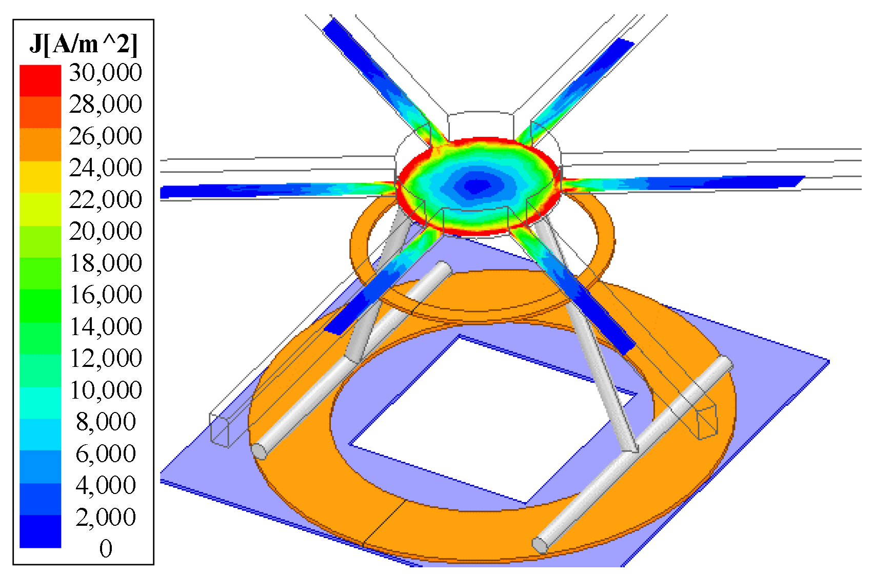
The eddy current is highly localized and concentrated on the outer edge of the carbon fiber fuselage in the Z-axis direction, as shown in Figure 2. Therefore, following the current distribution pattern from Figure 2, the fuselage can be modeled as an additional coil coupled with the transmitting and receiving coils, as shown in Figure 3.
In Figure 3, L1 and L2 represent the self-inductance of the transmitting and receiving coils, respectively. LCC-S compensation topology is adopted for a load-independent voltage output [15], and the other parameters can be determined by (1).
ω = 1 L 0 C 0 = 1 ( L 1 L 0 ) C 1 = 1 L 2 C 2
where ω is the operating angular frequency of 200 kHz. Compared with the previous research conducted by the author [16], this paper further gives the parameters of the fuselage equivalent coil and the theoretical formula for fuselage modeling. L3 is the equivalent coil of the UAV’s fuselage, referring to the equivalent method shown in [17]. R3 refers to the internal resistance of the fuselage when the eddy current is generated. L3 and R3 can be obtained by (2) and (3), respectively.
L 3 = μ r μ 0 r f ( ln ( 8 r f r w ) 2 )
R 3 = ρ l e f f A e f f
where μr is the relative permeability of carbon fiber, rf is the effective radius of the equivalent coil, and rw shows the radius of the equivalent circular wire. Aeff and leff are the equivalents of the conducting cross-sectional area and conducting path distance. ρ is resistivity, which is determined by the material and can be calculated in (4) [18].
ρ = 1 σ = π μ r μ 0 f δ 2
where f is the system frequency, δ is the skin depth of carbon fiber. According to the test results of fuselage materials, the conductivity of carbon fiber fuselage, σ, is about 8600 S/m. It should be emphasized that the modeling of the UAV is complex, and it is equivalent to a circular coil in this paper for simplicity. The parameter values in the above formula are shown in Table 1.
The above analysis illustrates that the UAV’s fuselage can be regarded as an additional coil, for which the parameters are associated with the material and system conditions, such as operating frequency. Thus, the circuit model shown in Figure 2 can be expressed as (5).
[ Z 0 1 j ω C 0 0 0 1 j ω C 0 Z 1 j ω M 12 j ω M 13 0 j ω M 12 Z 2 j ω M 23 0 j ω M 13 j ω M 23 Z 3 ] [ i 0 i 1 i 2 i 3 ] = [ U i n 0 0 0 ]
where M12, M13, and M23 are the mutual inductance between the corresponding coils, respectively. Z0~3 can be calculated as
{ Z 0 = j ω L 0 + 1 j ω C 0 Z 1 = j ω L 1 + 1 j ω C 1 + 1 j ω C 0 + R 1 Z 2 = j ω L 2 + 1 j ω C 2 + R 2 + R L Z 3 = j ω L 3 + R 3
i3 can be derived from (5).
i 3 = j ω M 13 i 1 + j ω M 23 i 2 Z 3
It is evident that the eddy current, i3, is a function of the transmitting and receiving coil currents. Thus, substituting (7) into (5) gives
[ Z 0 1 j ω C 0 0 1 j ω C 0 Z 1 j ω M 12 0 j ω M 12 Z 2 ] [ i 0 i 1 i 2 ] = [ U i n 0 0 ]
where
{ Z 1 = Z 1 + ( ω M 13 ) 2 Z 3 Z 2 = Z 2 + ( ω M 23 ) 2 Z 3 M 12 = M 12 + ω 2 M 13 M 23 Z 3
By substituting (6) into (9), (10) can be derived:
{ L 1 = L 1 ( ω M 13 ) 2 ω 2 L 3 2 + R 3 2 L 3 L 2 = L 2 ( ω M 23 ) 2 ω 2 L 3 2 + R 3 2 L 3 R 1 = R 1 + ( ω M 13 ) 2 ω 2 L 3 2 + R 3 2 R 3 R 2 = R 2 + ( ω M 13 ) 2 ω 2 L 3 2 + R 3 2 R 3 M 12 = M 12 ω 2 M 13 M 23 ω 2 L 3 2 + R 3 2 R 3
Equation (10) implies that the effective mutual inductance and self-inductance of the transmitting and receiving coils decline when the fuselage is considered, while the coil’s internal resistances increase. Such a phenomenon inevitably reduces system efficiency, which is also a critical problem for the carbon fiber UAV.
Figure 4 shows the variation in the mutual inductance, self-inductance, and internal resistance before and after the fuselage is added. Normalized values suggest that the fuselage has a more significant impact on internal resistance. Specifically, the receiving coil’s internal resistance is increased by six times, and the simulation results are consistent with (10). Therefore, it is necessary to reduce the coupling between the carbon fiber fuselage and the coils.
Furthermore, it is feasible to obtain the trend of coil–coil efficiency when the fuselage is added, as calculated in (11) [19].
η max = k 2 Q 1 Q 2 ( 1 + 1 + k 2 Q 1 Q 2 ) 2
where k is the coupling coefficient, and Q1,2 is the corresponding coil’s quality factor. Combined with the parameters in Figure 3, it can be calculated that the maximum efficiency declines from 94% to 85%.

3. Design of the Magnetic Coupler

3.1. Coil Parameters

The goal was to design a coupler with 500 W output and high efficiency. The transmission distance was set to 300 mm to simulate the hovering charging of the UAV. Thus, the coils were designed considering the following two aspects: to improve the mutual inductance and reduce coil loss.
First, the receiving coil was designed as simply as possible to reduce its weight. A four-turn, ferrite-free coil was fabricated, and its diameter was fixed at 400 mm.
Second, the mutual inductance under different transmitter diameters and a number of turns were plotted, as seen in Figure 5. The mutual inductance increases monotonously with the transmitter diameter and the number of turns, which implies that increasing these two parameters helps improve efficiency.
Third, the coil loss was analyzed. The coil loss can be obtained by calculating its induction and conduction resistances [20].
The coil resistance consists of conduction resistance and induced resistance, as shown in (12), represented by Rcond and Rindu.
R = R cond   + R indu  
where Rcond is the conduction resistance of the copper wire, expressed as
R cond   = 1 π r s 2 n 0 σ l
where rs is the single-strand radius of the Litz wire and n0 is the number of single-stranded Litz wires; σ is the conductivity of the material, and l is the total length of the Litz wire.
Rindu is the induced resistance caused by the eddy current effect [21,22], expressed as
R indu   = 4 n 0 π γ Φ indu   ( γ ) I 2 σ Γ H I 2 ( s ) d s
where Φindu(γ) and γ are represented by (15) and (16).
Φ indu   ( γ ) = b e r 2 ( γ ) b e r ( γ ) + b e i 2 ( γ ) b e i ( γ ) b e r 2 ( γ ) + b e i 2 ( γ )
γ = r s ξ = r s μ 0 μ r σ ω
In the above expression, ber, ber′, bei, and bei′ are Kelvin Bessel functions [23]. μ0 is the vacuum permeability (μ0 = 4π × 10−7 H/m), and μr is the relative permeability (for copper, μr = 1). ω is the angle operating frequency.
Figure 6 presents the coil loss under different diameters and the number of turns. Assuming that the output is constant, the coil loss increases with the diameter, and it rises more obviously when the number of turns exceeds nine. Therefore, a nine-turn coil is determined, and the diameter was set as 700 mm.

3.2. Ferrites Arrangement

As illustrated in Section 1, magnetic cores are usually eliminated, especially for the receiver, since weight is critical for the UAV. Therefore, in this paper, no ferrites were added to the receiver. For the transmitter, different types of ferrites were investigated, considering the relatively large air gap. The arrangement structures of the two commonly selected ferrites are shown in Figure 7 [24]. Flat-type and strip-type are compared with the case without ferrites, where the strip-type consists of 12 ferrite bars.
First, the mutual inductances of these cases were simulated (plotted in Figure 8). It was found that the flat type can improve the mutual inductance by 50% compared with the strip type.
Second, the core loss is also analyzed to choose a better scheme. The core loss can be obtained as per (17).
P c o r e = C m f α B m β
where Cm, α, and β are the Steinmetz coefficients obtained from the selected core material datasheet. In order to realize high efficiency, it is essential to consider the trade-off between ferrite consumption and core loss. Compared with the strip type, Figure 8 implies that the flat type has better performance in both mutual inductance and core loss. Thus, the flat type is selected in this paper.

3.3. Reduce the Effect of the Fuselage with Nanocrystalline Alloy Film

To avoid the efficiency reduction caused by the coupling between the fuselage and coils, the shielding needed to be designed. The fuselage of a UAV is a heteromorphic structure, and the arm is a cylinder. The ferrite, aluminum, and other materials often used in previous research can not be placed close under the fuselage, so light and flexible magnetic materials need to be used, namely nanocrystalline alloy soft magnetic materials. With the development of preparation technology for nanocrystalline alloys, the saturation magnetic induction intensity and permeability of nanocrystalline materials are greatly improved. The nanocrystalline soft magnetic material is superior to conventional Mn-Zn ferrite materials, reflected in higher saturation magnetic flux density, a lighter weight, and higher plasticity [20,25].
However, due to the high conductivity of nanocrystalline materials, eddy currents will be generated in a 200 kHz magnetic field. Therefore, heat treatment and mechanical crushing can be used to reduce the eddy current loss of nanocrystalline magnetic materials [26]. The relative permeability of the nanocrystalline magnetic core decreases macroscopically, and the greater the degree of grain refinement, the more the relative permeability decreases. In general, the smaller the relative permeability, the smaller the core loss and AC resistance, and the higher the quality factor.
The relative permeability directly determines the mutual inductance between the coils. Therefore, it is necessary to determine the lower limit boundary value of the influence of the relative permeability on the system and reduce the relative permeability on the premise of ensuring mutual coupler inductance. In this paper, nanocrystalline materials with a relative permeability of 1000 are made and used, and the conductivity is about 8300 S/m. The parameters of nanocrystalline alloy film are listed in Table 2. The layered structure of the nanocrystalline alloy film is shown in Figure 9.
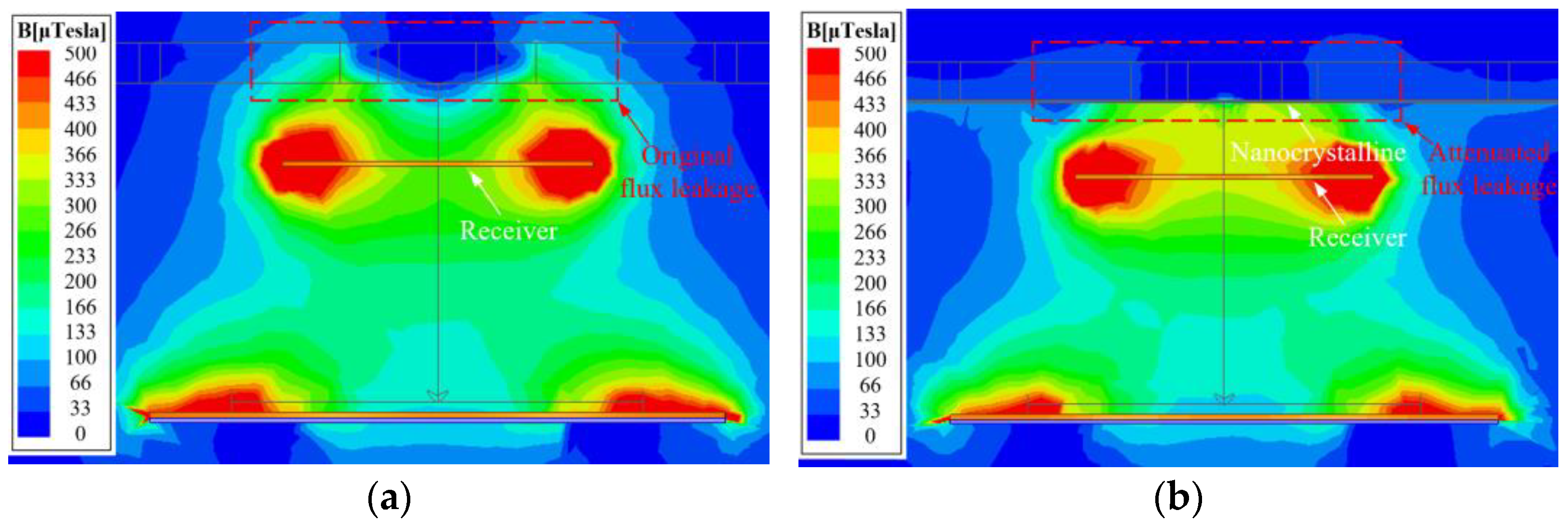
As shown in Figure 10 and Figure 11, adding a nanocrystalline alloy film can effectively suppress the flux leakage, and the coupling between the fuselage and coils can be weakened.
According to the theory in Section 2, the carbon fiber fuselage is modeled as a single-turn coil, as shown in Figure 12. The results obtained from the finite element calculation via the Galerkin weighted residual method (and other methods) are approximately accurate, but the causes of the results cannot be analyzed systematically, and the intermediate process cannot be given. The equivalent magnetic circuit model based on finite element simulation can characterize the influence of the magnetic coupling mechanism parameters on mutual inductance and the coupling coefficient. The equivalent magnetic circuit model was established to analyze the effect of the nanocrystalline alloy film, as shown in Figure 13.
The parameters of the left and right half of the coil are symmetrical, and only the parameters of the left half are discussed. F1 is the magnetomotive force aroused by winding, Rair is the magnetic resistance of air, Rcore-1 is the magnetic resistance of ferrites, Rcore-2 is the magnetic resistance of the nanocrystalline cores, and Rm is the sum of the magnetic resistance of mutual inductance flux branch. Φp is the magnetic flux of self-inductance, Φm-1 is the mutual inductance flux of the coupler, and Φm-2 is the mutual inductance flux between the carbon fiber fuselage and the coupler.
According to Kirchhoff’s voltage law of magnetic circuits, the self-inductance and mutual inductance magnetic flux are:
{ Φ p = N p I p R m ( R air- 2 + R m ) R core- 1 + R air- 2 R m Φ m = N p I p R air- 2 ( R air- 2 + R m ) R core- 1 + R air- 2 R m
When the magnetic flux, Φm, is excited by the transmitting coil passing through the receiving coil with the number of turns, Ns, this forms mutual inductance flux linkage:
Ψ m = N s Φ m
Further calculations show that the mutual inductance of the transmitting and receiving coils are:
M = Ψ m I p = N p N s R air- 2 ( R air- 2 + R m ) R core- 1 + R air- 2 R m
k = Φ m Φ m + Φ p = 1 1 + R m R air- 2
Therefore, in order to improve mutual inductance and improve system efficiency, we considered reducing Rm, with Rm expressed as
{ R m = R air- 1 + R air- 3 + R f R core- 2 R f + R core- 2 R f = r f 2 μ 0 ( r s + r f ) r w R core- 2 = 1 2 μ r μ 0 t s
According to the parameters, Rcore-2 << Rair-4, Φm-1 >> Φm-2, the influence of carbon fiber fuselage on the magnetic coupler is weakened by nanocrystals. The above qualitative analysis of the impact on nanocrystals will help to optimize materials in the future. It is convenient for us to understand the action mechanism of nanocrystalline and provide the direction for optimizing nanocrystalline and the system.
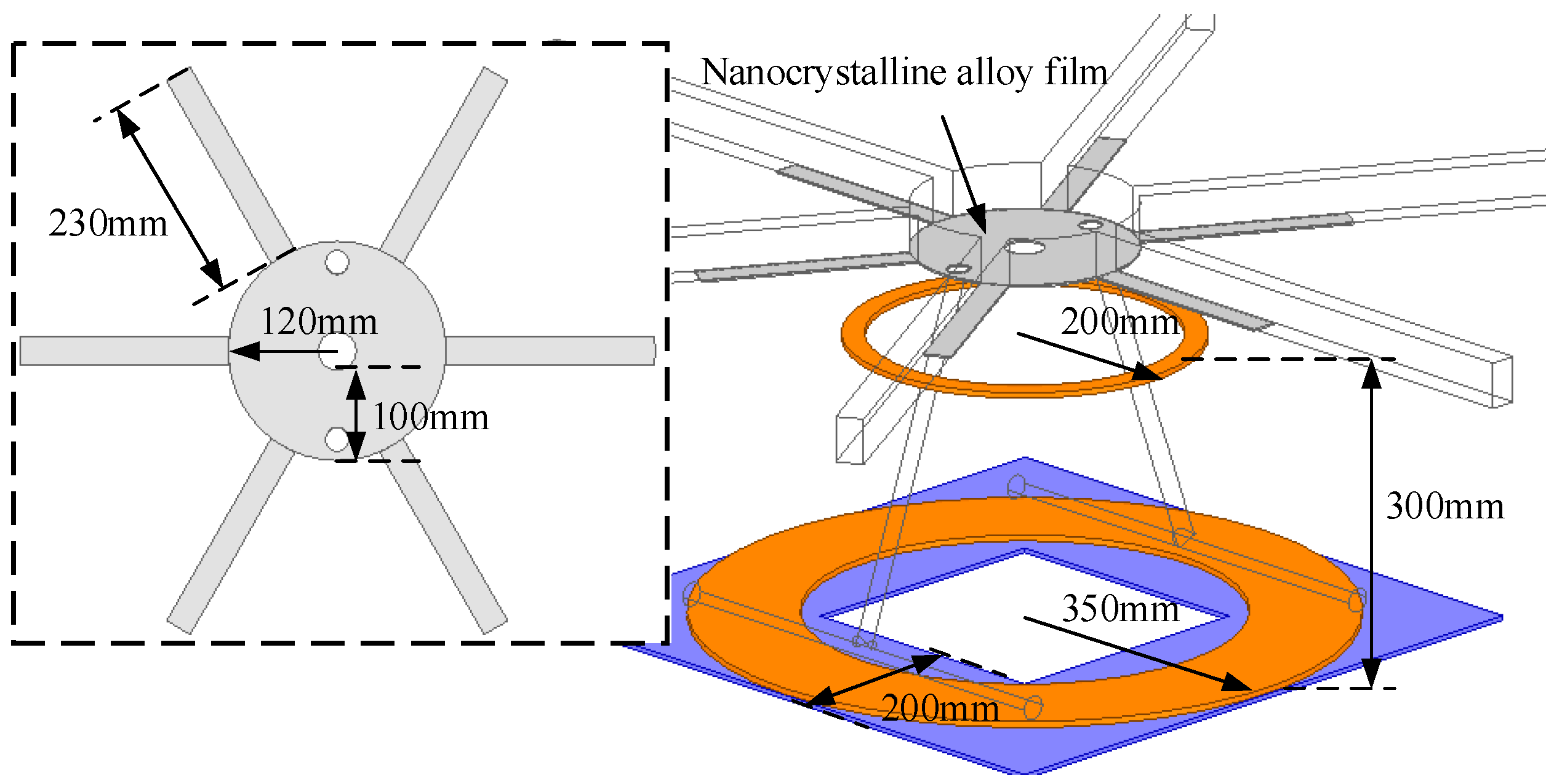
The nanocrystalline alloy film’s structure was optimized. In order to reduce material consumption, the nanocrystalline alloy film was redesigned as a ring, for which the width needed to be determined, as shown in Figure 14. The trend of the mutual inductance and loss vs. the width is plotted in Figure 15. The mutual inductance is almost independent of the width, and the loss caused by the fuselage decreases obviously with the width. When the width exceeds 100 mm, the variation in fuselage loss becomes gentle. Consequently, the width of the nanocrystalline alloy ring is 100 mm. In order to shield the eddy current loss caused by the carbon fiber arm, strip nanocrystalline alloy films with a length of 230 mm were added under the arm.

3.4. Simulation of Eddy Current Loss

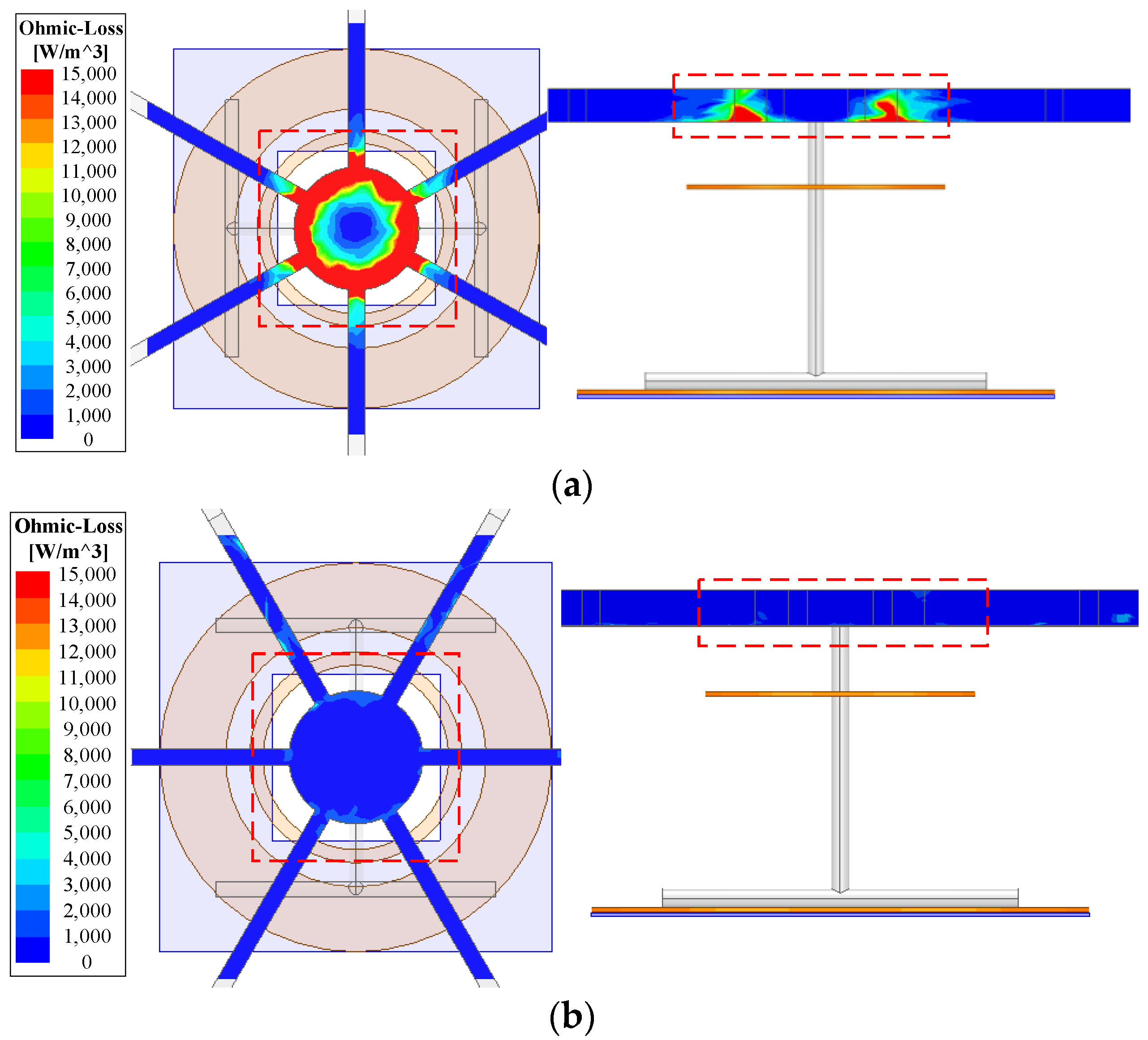
The design procedure of the magnetic coupler is given above. The focus is on the trade-off between mutual inductance and loss to improve efficiency. Figure 16 shows the eddy current loss distribution with and without nanocrystalline alloy. It is evident that much more of the losses are generated on the fuselage without the nanocrystalline alloy, and the designed nanocrystalline alloy film can significantly reduce the eddy current loss. Accordingly, the undesirable impact caused by the fuselage is reduced.

4. Experimental Verification

4.1. Experimental Setup

The prototype for wireless UAV charging is shown in Figure 17. The carbon fiber UAV with a 24 V Li-ion battery (22,000 mAh, 25C) is adopted. The transmitting coil is embedded in a charging platform, and the receiving coil is integrated with the fuselage. Power frequency, AC, is used to supply power to the portable transmitter’s power source. The detailed coil parameters are listed in Table 3.

4.2. Results

The following three cases: (i) without UAV, (ii) with UAV but without nanocrystalline, and (iii) with UAV and nanocrystalline were validated and compared. The output power and coil–coil efficiency were measured and recorded by the power analyzer Yokogawa PX8000. Carbon fiber fuselage temperature was measured and recorded by the thermodetector Fluke TiS60+.
(i) Without UAV
This case is representative of the previous research since the UAV material is generally not considered. The output power and efficiency were recorded and are shown in Figure 18. A coil–coil efficiency of nearly 93% is consistent with the calculation results of (10), which proves that the design approach is reasonable when the fuselage is not considered.
(ii) With UAV But Without Nanocrystalline
When the UAV is added, as is shown in Figure 17, the variation in output power and efficiency is presented in Figure 19. It is worth noting that the efficiency was reduced by over 10%, which agrees with the curves in Figure 4. Besides, the resonant frequency was disturbed due to the change in the effective self-inductances. The temperature of the UAV fuselage after 20 min of operation of the wireless charging system is shown in Figure 20. The maximum temperature of the UAV fuselage was 70.2 °C. The carbon fiber fuselage of a UAV creates a lot of eddy current loss, which is consistent with the theoretical analysis.
(iii) With UAV and Nanocrystalline
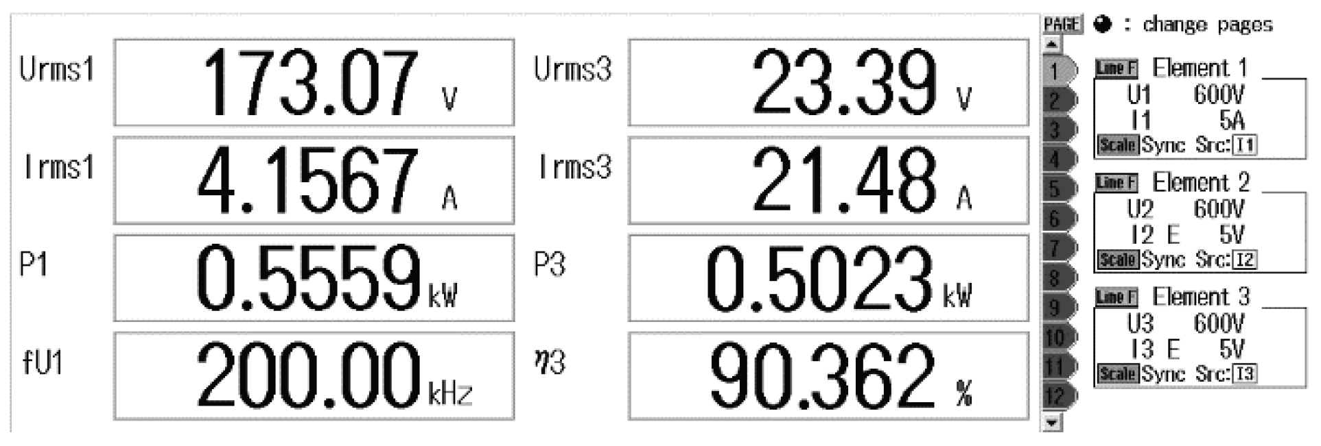
The nanocrystalline alloy film is placed above the receiving coil to suppress the coupling between the fuselage and coils. As recorded in Figure 21, the efficiency improved to 90% after adding the nanocrystalline alloy film.
Compared with the case without UAV, the efficiency is slightly lower because the coupling between the fuselage and coils cannot be eliminated, and the additional nanocrystalline alloy film causes some loss. Working waveforms with UAV and nanocrystalline is shown in Figure 22. The loss distribution of the magnetic coupler is shown in Figure 23.
Figure 24 shows the comparison between the experimental results (with UAV but without nanocrystalline) and the above theoretical analysis. The system parameters after adding the carbon fiber fuselage are consistent with the theoretical analysis.
The temperature of the UAV fuselage with nanocrystalline after 20 min of operation of the wireless charging system is shown in Figure 25. The maximum temperature of the UAV fuselage was 40.9 °C. The loss caused by the fuselage was effectively restrained.

4.3. Comparison with Previous Work

The designed prototype was compared with some previous works regarding distance, efficiency, power, and materials, as listed in Table 4. First, the longest transmission distance is highlighted compared with the references. Second, the power is slightly higher than the references, and the efficiency is relatively high considering the longest distance. Finally, the impact of the carbon fiber fuselage was not investigated in the previous work, which is one of this paper’s focuses.

5. Conclusions

This paper proposes a magnetic coupler with nanocrystalline cores for the improvement of UAV wireless charging system efficiency. First, the impact of the carbon fiber fuselage is investigated, which has been typically neglected by previous research. It was found that the effective mutual inductance declined, but the equivalent coil resistance increased when the fuselage was considered. Consequently, the system’s efficiency was reduced significantly. Second, aiming at high mutual inductance and low losses, the magnetic coupler’s parameters, including coils, ferrites, and nanocrystalline, were designed. Third, to weaken the coupling between the fuselage and the coils, an optimized nanocrystalline alloy film was placed under the fuselage, making a trade-off between effectiveness and consumption. The efficiency reduction caused by the fuselage could almost be compensated for. Finally, the designed 500 W prototype, for which the efficiency is 90.3%, validates our theoretical analysis and simulation. In future work, we might further enrich the process of UAV fuselage modeling and improve its accuracy. At the same time, the influence of the fuselage and nanocrystalline can be considered with regard to cases of misalignment between the UAV and the transmitter.

Author Contributions

Theoretical analysis, K.S. and J.J.; simulation, C.S.; material preparation, A.H.; experiment, W.C. and Y.L.; writing—original draft preparation, F.Y. All authors have read and agreed to the published version of the manuscript.

Funding

This research received no external funding.

Conflicts of Interest

The authors declare no conflict of interest.

References

  1. Motlagh, N.; Taleb, T.; Arouk, O. Low-altitude unmanned aerial vehicles-based Internet of Things services: Comprehensive survey and future perspectives. IEEE Internet Things J. 2016, 3, 899–922. [Google Scholar] [CrossRef]
  2. Berni, J.A.J.; Zarco-Tejada, P.J.; Suarez, L.; Fereres, E. Thermal and narrowband multispectral remote sensing for vegetation monitoring from an unmanned aerial vehicle. IEEE Trans. Geosci. Remote Sens. 2009, 47, 722–738. [Google Scholar] [CrossRef] [Green Version]
  3. Dong, J.; Ota, K.; Dong, M. UAV-based real-time survivor detection system in post-disaster search and rescue operations. IEEE J. Miniat. Air Space Syst. 2021, 2, 209–219. [Google Scholar] [CrossRef]
  4. Obayashi, S.; Kanekiyo, Y.; Nishizawa, K.; Kusada, H. 85-kHz band 450-W inductive power transfer for unmanned aerial vehicle wireless charging port. In Proceedings of the 2019 IEEE Wireless Power Transfer Conference (WPTC), London, UK, 18–21 June 2019; pp. 80–84. [Google Scholar]
  5. Xu, J.; Zeng, Y.; Zhang, R. UAV-enabled wireless power transfer: Trajectory design and energy optimization. IEEE Trans. Wirel. Commun. 2018, 17, 5092–5106. [Google Scholar] [CrossRef] [Green Version]
  6. Cai, C.; Wu, S.; Jiang, L.; Zhang, Z.; Yang, S. A 500-W wireless charging system with lightweight pick-up for unmanned aerial vehicles. IEEE Trans. Power Electron. 2020, 35, 7721–7724. [Google Scholar] [CrossRef]
  7. Campi, T.; Dionisi, F.; Cruciani, S.; De Santis, V.; Feliziani, M.; Maradei, F. Magnetic field levels in drones equipped with wireless power transfer technology. In Proceedings of the 2016 Asia-Pacific International Symposium on Electromagnetic Compatibility (APEMC), Shenzhen, China, 17–21 May 2016; pp. 544–547. [Google Scholar]
  8. Campi, T.; Cruciani, S.; Feliziani, M.; Maradei, F. High efficiency and lightweight wireless charging system for drone batteries. In Proceedings of the 2017 AEIT International Annual Conference, Cagliari, Italy, 20–22 September 2017; pp. 1–6. [Google Scholar]
  9. Han, W.; Chau, K.T.; Jiang, C.; Liu, W.; Lam, W.H. Design and analysis of quasi-omnidirectional dynamic wireless power transfer for Fly-and-Charge. IEEE Trans. Magn. 2019, 55, 8001709. [Google Scholar] [CrossRef]
  10. Wu, S.; Cai, C.; Jiang, L.; Li, J.; Yang, S. Unmanned aerial vehicle wireless charging system with orthogonal magnetic structure and position correction aid device. IEEE Trans. Power Electron. 2021, 36, 7564–7575. [Google Scholar] [CrossRef]
  11. Arteaga, J.M.; Aldhaher, S.; Kkelis, G.; Kwan, C.; Yates, D.C.; Mitcheson, P.D. Dynamic capabilities of multi-MHz inductive power transfer systems demonstrated with batteryless drones. IEEE Trans. Power Electron. 2019, 34, 5093–5104. [Google Scholar] [CrossRef]
  12. Campi, T.; Cruciani, S.; Maradei, F.; Feliziani, M. Wireless charging system integrated in a small unmanned aerial vehicle (UAV) with high tolerance to planar coil misalignment. In Proceedings of the 2019 Joint International Symposium on Electromagnetic Compatibility, Sapporo and Asia-Pacific International Symposium on Electromagnetic Compatibility (EMC Sapporo/APEMC), Sapporo, Japan, 3–7 June 2019; pp. 601–604. [Google Scholar]
  13. Campi, T.; Cruciani, S.; Rodriguez, G.; Feliziani, M. Coil design of a wireless power transfer charging system for a drone. In Proceedings of the 2016 IEEE Conference on Electromagnetic Field Computation (CEFC), Miami, FL, USA, 13–16 November 2016; p. 1. [Google Scholar]
  14. Ke, D.; Liu, C.; Jiang, C.; Zhao, F. Design of an effective wireless air charging system for electric unmanned aerial vehicles. In Proceedings of the IECON 2017—43rd Annual Conference of the IEEE Industrial Electronics Society, Beijing, China, 29 October–1 November 2017; pp. 6949–6954. [Google Scholar]
  15. Song, K.; Zhang, P.; Chen, Z.; Yang, G.; Jiang, J.; Zhu, C. A high-efficiency wireless power transfer system for unmanned aerial vehicle considering carbon fiber body. In Proceedings of the 2020 22nd European Conference on Power Electronics and Applications (EPE’20 ECCE Europe), Lyon, France, 7–11 September 2020; pp. 1–7. [Google Scholar]
  16. Yang, F.; Song, K.; Zhang, P.; Zhang, J.; Zhu, C. Design of high power density wireless charging system for unmanned aerial vehicle. In The Proceedings of the 16th Annual Conference of China Electrotechnical Society; Springer: Singapore, 2022; p. 891. [Google Scholar]
  17. Mohammad, M.; Wodajo, E.T.; Choi, S.; Elbuluk, M.E. Modeling and design of passive shield to limit EMF emission and to minimize shield loss in unipolar wireless charging system for EV. IEEE Trans. Power Electron. 2019, 34, 12235–12245. [Google Scholar] [CrossRef]
  18. Dengler, R. Self inductance of a wire loop as a curve integral. Adv. Electromagn. 2016, 5, 1–8. [Google Scholar] [CrossRef]
  19. Cheng, C.; Li, W.; Zhou, Z.; Li, W.; Zhu, C.; Zhang, H.; Deng, Z.; Chen, X.; Mi, C.C. A load-independent wireless power transfer system with multiple constant voltage outputs. IEEE Trans. Power Electron. 2020, 35, 3328–3331. [Google Scholar] [CrossRef]
  20. Xiong, M.; Wei, X.; Huang, Y.; Luo, Z.; Dai, H. Research on novel flexible high-saturation nanocrystalline cores for wireless charging systems of electric vehicles. IEEE Trans. Ind. Electron. 2021, 68, 8310–8320. [Google Scholar] [CrossRef]
  21. Liu, J.; Deng, Q.; Czarkowski, D.; Kazimierczuk, M.K.; Zhou, H.; Hu, W. Frequency optimization for inductive power transfer based on AC resistance evaluation in litz-wire coil. IEEE Trans. Power Electron. 2019, 34, 2355–2363. [Google Scholar] [CrossRef]
  22. Rosskopf, A.; Bar, E.; Joffe, C. Influence of inner Skin- and Proximity effects on conduction in litz wires. IEEE Trans. Power Electron. 2014, 29, 2355–2363. [Google Scholar] [CrossRef]
  23. Abramowitz, M.; Stegun, I. Handbook of Mathematical Functions; Dover Publications: New York, NY, USA, 1970. [Google Scholar]
  24. Jayalath, S.; Khan, A. Design, challenges, and trends of inductive power transfer couplers for electric vehicles: A review. IEEE J. Emerg. Sel. Top. Power Electron. 2021, 9, 6196–6218. [Google Scholar] [CrossRef]
  25. Gaona, D.E.; Jiang, C.; Long, T. Highly efficient 11.1-kW wireless power transfer utilizing nanocrystalline ribbon cores. IEEE Trans. Power Electron. 2021, 36, 9955–9969. [Google Scholar] [CrossRef]
  26. Wang, D.; Cui, S.; Zhang, J.; Bie, Z.; Song, K.; Zhu, C. A novel arc-shaped lightweight magnetic coupler for AUV wireless power transfer. IEEE Trans. Ind. Appl. 2022, 58, 1315–1329. [Google Scholar] [CrossRef]
  27. Aldhaher, S.; Mitcheson, P.D.; Arteaga, J.M.; Kkelis, G.; Yates, D.C. Lightweight wireless power transfer for mid-air charging of drones. In Proceedings of the 2017 11th European Conference on Antennas and Propagation (EUCAP), Paris, France, 19–24 March 2017; pp. 1–5. [Google Scholar]
  28. Zhang, H.; Chen, Y.; Jo, C.-H.; Park, S.-J.; Kim, D.-H. DC-link and switched capacitor control for varying coupling conditions in inductive power transfer system for unmanned aerial vehicles. IEEE Trans. Power Electron. 2021, 36, 5108–5120. [Google Scholar] [CrossRef]
  29. Campi, T.; Cruciani, S.; Feliziani, M. Wireless power transfer technology applied to an autonomous electric UAV with a small secondary coil. Energies 2018, 11, 352. [Google Scholar] [CrossRef]
Figure 1. General overview of the proposed magnetic coupler. (a) Original 3D model; (b) simplified 3D model.
Energies 15 08363 g001
Figure 2. Eddy current distribution of carbon fiber fuselage.
Energies 15 08363 g002
Figure 3. Equivalent circuit model.
Energies 15 08363 g003
Figure 4. Variation in the mutual inductance, self-inductance, and resistance.
Energies 15 08363 g004
Figure 5. Mutual inductance vs. transmitter diameter and the number of turns.
Energies 15 08363 g005
Figure 6. Coil loss vs. transmitter diameter and the number of turns.
Energies 15 08363 g006
Figure 7. Two ferrite structures. (a) flat type and (b) strip type.
Energies 15 08363 g007
Figure 8. Mutual inductances and core losses of three cases.
Energies 15 08363 g008
Figure 9. The layered structure of the nanocrystalline alloy film.
Energies 15 08363 g009
Figure 10. Flux leakage with and without nanocrystalline. (a) Without nanocrystalline and (b) with nanocrystalline.
Energies 15 08363 g010
Figure 11. Comparison between the fuselage with and without nanocrystalline.
Energies 15 08363 g011
Figure 12. Equivalent model of carbon fiber fuselage.
Energies 15 08363 g012
Figure 13. Magnetic circuit model of the proposed magnetic coupler.
Energies 15 08363 g013
Figure 14. Magnetic circuit model of the proposed magnetic coupler.
Energies 15 08363 g014
Figure 15. Mutual inductance and loss vs. width.
Energies 15 08363 g015
Figure 16. Eddy current loss distribution. (a) Without nanocrystalline and (b) with nanocrystalline.
Energies 15 08363 g016
Figure 17. Experimental prototype. (a) Experimental system and (b) portable transmitter’s power source.
Energies 15 08363 g017
Figure 18. Output characteristics without UAV.
Energies 15 08363 g018
Figure 19. Output characteristics with UAV.
Energies 15 08363 g019
Figure 20. Carbon fiber fuselage temperature.
Energies 15 08363 g020
Figure 21. Output characteristics with UAV and nanocrystalline.
Energies 15 08363 g021
Figure 22. Working waveforms with UAV and nanocrystalline.
Energies 15 08363 g022
Figure 23. Loss distribution of the UAV magnetic coupler.
Energies 15 08363 g023
Figure 24. Comparison between experiment and theory.
Energies 15 08363 g024
Figure 25. Carbon fiber fuselage temperature with nanocrystalline.
Energies 15 08363 g025
Table 1. Parameters of the fuselage equivalent coil.
ParametersValue
μr1
rf120 mm
rw15 mm
Aeff706 mm2
leff94 mm
f200 kHz
δ12 mm
σ8600 S/m
Table 2. Parameters of nanocrystalline alloy.
TypeTypeType
Alloy ribbonSaturation magnetic induction1.24 T
Coercivity0.7 A/m
Curie temperature570 °C
Volume resistivity120 μΩ·m
Core loss (0.2 T, 100 kHz)180 kW/m3
Flexible filmPermeability1000 Gs/Oe
Thickness0.11 mm
Table 3. Detailed coil parameters.
ParameterType
Transmitting coilDiameters700 mm
Number of turns9
Self-inductance135 μH
Diameters400 mm
Receiving coilNumber of turns4
Self-inductance14 μH
Air gap300 mm
Coupling coefficient0.1
Litz wireΦ0.05 mm, 4200 stranded
L020 μH
C031.6 nF
C15.5 nF
C245.2 nF
Table 4. Characteristic parameters of the proposed prototype vs. references.
ReferencesDistance/mmEfficiency/%Power/WMaterials
This paper30090500Carbon fiber
[4]15N/A450No real UAV
[6]2590500Plastics
[8]1090144Engineering plastics
[10]N/A87100Plastics
[27]120N/A10Plastics
[28]2091500No real UAV
[29]108575Engineering plastics
Publisher’s Note: MDPI stays neutral with regard to jurisdictional claims in published maps and institutional affiliations.