Article

Selected Issues Associated with the Operational and Power Supply Reliability of Fire Alarm Systems

1
Constructions Safety Department, The Main School of Fire Service, 52/54 J. Słowackiego St., 01-629 Warsaw, Poland
2
Division of Electronic Systems Exploitations, Institute of Electronic Systems, Faculty of Electronics, Military University of Technology, 2 Gen. S. Kaliski St., 00-908 Warsaw, Poland
3
Department of Energy, Faculty of Mechanical Engineering, Technical University of Koszalin, 15–17 Raclawicka St., 75-620 Koszalin, Poland
4
Division of Air Transport Engineering and Teleinformatics, Faculty of Transport, Warsaw University of Technology, 75 Koszykowa St., 00-662 Warsaw, Poland
5
Signalling and Telecommunications Laboratory, Railway Research Institute, 50 Chłopickiego St., 04-275 Warsaw, Poland
6
Doctoral School, Faculty of Electronics, Military University of Technology, 2 Gen. S. Kaliski St., 00-908 Warsaw, Poland
*
Author to whom correspondence should be addressed.
Energies 2022, 15(22), 8409; https://doi.org/10.3390/en15228409
Submission received: 3 October 2022 / Revised: 2 November 2022 / Accepted: 6 November 2022 / Published: 10 November 2022

Abstract

:
The article reviews issues associated with the use of electronic fire alarm systems (FAS). They are operated in various environments and buildings with varying volumes. FAS have to function properly under different operating conditions associated with their operation, as well as power supply and information inflow. Due to their functions, i.e., ensuring the safety of people, vehicles, logistics bases, airports, etc., FAS have to exhibit an appropriately organized reliability structure associated with their implementation and power supply. Operational studies involving FAS operated in various facilities were conducted to this end. The authors determined damage and recovery time intensities. FAS reliability indicators were also determined. The article presents graphs associated with developing the energy balance for selected FAS. The graphs are consistent with the latest and applicable legal regulations. The next stage of the work related to this article was developing an FAS operation process model and conducting computer simulations in order to determine reliability indicators. Such an approach to the FAS operation process enables a rational selection of technical and organizational solutions aimed at guaranteeing reliability in the course of executing operational tasks associated with ensuring fire safety. FAS operational analysis, developing balance graphs and models, as well as the computer simulation, enabled inferring conclusions that might be useful to the process of engineering and operating such systems.

1. Introduction

The task of electronic security systems (ESS)- these operated in buildings or over a vast area, e.g., a logistics base or airport-such as fire alarm systems (FAS) is to ensure the safety of people and property located at a given moment in rooms within the area in question [1,2]. It also includes ensuring the safety of transported materials and transport vehicle movement. When operating FAS in the case under consideration, the above also covers the safety of the natural environment, external and internal within a vast area in the case of fire monitoring tanks with fuel, lubricants, and substances hazardous to humans when a fire breaks out. Most often, the facilities are buildings, warehouses, hubs, logistics bases, airports, etc. located in vast areas monitored by FAS. In such a case, they are part of the so-called state critical infrastructure facilities [3,4,5]. The most important tasks implemented by these systems located within a vast area include guaranteeing fire safety [6,7,8]. FAS elements, modules, and devices are located inside protected buildings, but also in a publicly available outdoor environment. In such a case they are exposed to the adverse impact of changing external environmental factors—e.g., temperature, pressure, or humidity. Additionally, the Earth’s natural environment, namely, the existing electric and magnetic fields, is distorted by the presence of unintentional electromagnetic interference over different spectral bands of frequency generated by, e.g., LV, MV, or HV power supply circuits, TV, and radio transmitters, cell-phone base stations, radar stations, CB radio transmitters, railway overhead contact lines, etc. [9,10,11]. Fire alarm systems and other electronic security systems operated in buildings and over a vast area predominantly apply elements, systems, and microprocessors utilizing digital technology for processing and converting primary signals originating from fire sensors that react to characteristic attributes of a fire—e.g., temperature, smoke, or electromagnetic radiation, etc. [12,13].
The presence of electromagnetic interference and abrupt external environment parameter changes can lead to an increased probability of a false alarm by FAS installed in buildings or over a vast area [14,15]. This may result in serious consequences, e.g., economic, such as suspending transport traffic, air, or rail, as well as announcing the evacuation of humans through an audio warning system (AWS), directly or indirectly connected to a fire alarm control unit (FACU) Figure 1 [16,17].
FAS is impacted by different internal and external interference, advantageous or disadvantageous to the process of operation within the surrounding environment (Figure 1). Their sources are of different natures—electrical, mechanical, temperature-related, or deliberate human actions—e.g., sabotage, etc. Regardless of these disturbing impacts, an FAS should remain in a state of equilibrium—technical and functional efficiency S0(t), which is defined by a triangle of adverse impacts (Figure 1). External environmental factors impact the FAS operation process directly through actions associated with changes in interfering signal levels (amplitudes): EZ(t)-action related to electromagnetic interference, K(t)-external climate (environmental) conditions, favourable or unfavourable to an FAS operation process and M(t)-internal mechanical environmental interference (e.g., vibrations of the ground, walls, partitions or air, etc.). Similar disturbing actions occur also inside a building with an installed operated FAS-EW(t), Mw(t) and Kw(t). However, the nature and amplitude levels of these disturbances are different. For example, attenuation of vibrations, electromagnetic interference or temperature changes by existing building partitions, windows or walls should be taken into account [18,19,20]. The FAS operation process should also consider the human factor, associated with protected, separated fire zones. Human impact on an FAS may be advantageous (e.g., implementation of the maintenance process, system repair) and disadvantageous, such as intentional triggering of a fire alarm by a deceptively starting fire in a facility, sabotage or terrorist attack through causing panic or an explosion. There is also the possibility of unauthorized actuation (breaking the glass) of a manual call point (MCP), which triggers a fire alarm 2nd stage [1,2,13]. A fire alarm system may be activated (switch from a state of detection to a state of alarm) due to the occurrence of various fire characteristics detector sensors-temperature, smoke, electromagnetic radiation-true alarm, or due to, e.g., excessive levels of various interference signals-false alarm. Especially the latter alarm case is undesirable for an FAS, which limits the probability of a false alarm using different technical and organizational solutions. The consequence of triggering a false alarm within the operation process of FAS used in railway buildings (e.g., platforms, main station buildings, underground passages to platforms, signal boxes, etc.) include enormous economic losses (e.g., suspension of train traffic, announcing evacuation and calling law enforcement services and the fire service to the station, activation of gas suppression systems in server rooms, switchgear rooms and rooms housing railway traffic control equipment or activation of fixed water extinguishing devices-sprinklers or sprays, etc.). A correctly organized, operated, supervised and designed FAS, despite the impact of internal and external interference (Figure 1), should always remain in the S0(t) technical state– state of operational fitness [1,2]. However, violating the state of equilibrium of this process is a function of numerous variables, dependent on human activity and the surrounding environment Figure 1. Figure 2 shows an example of an ESS structure organized over a vast area (e.g., airport, railway area, logistic or military bases, etc.). Such structures and the land they cover are classified as the so-called critical infrastructure (CI) of a given state. They implement tasks that are crucial from the functional perspective of a given country, e.g., related to transport, military, power-power plants, transformer stations or substations, as well as administration -buildings housing courts, ministries, offices, police and other services, ports and sea bases, airports, railway routes, etc. [1,4,14].
A very important issue related to the functioning of ESS located within such areas is ensuring power supply continuity-which is achieving the highest possible reliability of electricity supply continuity [4,21,22]. It is achieved by supplying a given area from two independent power plants, E1 and E2-Figure 2, with full redundancy of all elements ensuring electricity transmission located along given transmission lines. The unfitness of the E1 power plant or this transmission circuit to the consumer automatically leads to the consumers switching to power from the E2 power plant. It is implemented through power switch No. 1 (automatic backup power switch-ABPS). In the event of unfitness of the E1 and E2 power plants, the power supply of security systems is taken over by a power generator connected to the consumers located over a vast area through switch No. 2. Additional ESS equipment for ensuring power supply continuity, hence, protection (security) of all facilities within a vast area are additional power sources–a battery bank or UPS [1,23,24]. Most usually, these backup power sources are located in a special room, which also houses the control and service elements of security systems-Figure 2. If one of such sources is unfit, ESS consumers are automatically switched (power switches No. 3 and 4) to backup supply with simultaneous system installation location failure signal transmission to an alarm receiving centre (ARC) and law enforcement authorities via alarm and failure signal transmitters (antennas No. 1 and 2). In Figure 2, the room where continuous supervision of the ESS operation process is located, can be found in Building No. 1, located over a vast area. The entire area is monitored by peripheral security (No. 1) on long approaches to protected facilities using CCTV, a low-power radar station and fence sensors notifying about the presence of unwanted persons-e.g., burglars or terrorists-Figure 2 [1,25]. Some of the most important electronic security systems operated within buildings (1, 2, 3, 4) over vast areas are fire alarm systems integrated with audio warning systems (AWS) broadcasting alarm signals in a given facility. The installation and operation, maintenance or service of FAS and AWS is governed by legal regulations applicable within a given country for buildings particularly important to state interests, so-called critical infrastructure. For example, in Poland this duty is imposed by the regulation of the Minister of Interior and Administration on fire protection of buildings, other building structures and land. [5,8].
FAS are not integrated with other electronic security systems that may be located in rooms and buildings located over a vast area. These systems—FAS and AWS, in particular—can exchange information on the primary or backup power supply status and switch to backup power. These systems do not exchange information on sabotage, intrusion, etc. Furthermore, the aforementioned information on the technical condition of the systems is sent via two independent signal transmission chains to a remote alarm centre, law enforcement service (e.g., the police), and the State Fire Service (PSP), in this case only the alarm (fire) and failure signals originating from the fire alarm system [1,8]. Depending on the area and volume of a given facility, an FAS may vary in terms of its functional structure. These include a concentrated FAS (Figure 2), where all detection circuits and loops are hooked up to a single fire alarm control unit (FACU). The other two types are scattered FAS, which utilizes several or a dozen or so FACUs operating under various configurations (e.g., loop, star, or bus), and mixed FAS (scattered systems and additionally established concentrated systems) [1,2]. In addition, all facilities and the rooms therein may be monitored by other ESSs in order to ensure an adequate security level—e.g., most common are the intrusion detection system (IDS), closed-circuit television (CCTV) or access control systems (ACS)-(Figure 2). For purposes of clarity of the entire figure, Figure 2 does not show the connection and integration of the aforementioned systems. In most cases, such facilities operate IDS, ACS, or CCTV systems. An important technical issue when determining the battery capacity and UPS power is the operating (functioning) time of such ESS operated in such facilities [1,2,7,12]:
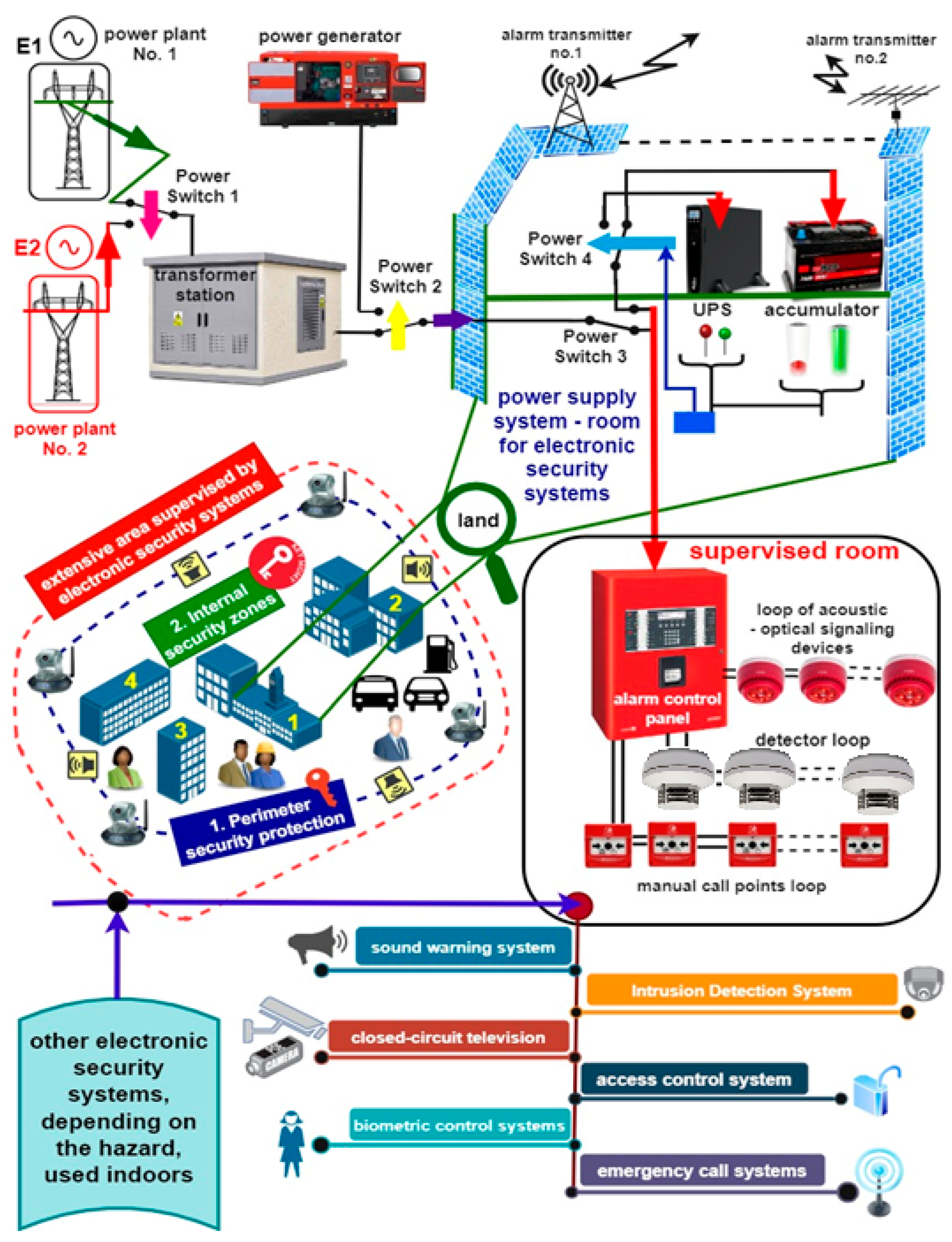
  • in the basic operating mode of all ESS, without detection of a burglary or intrusion and fire-technical state-monitoring;
  • in the event of the aforementioned hazards occurring-alarm state.
These two cases involve conducting calculations of the so-called energy balance (or current balance in other words), which takes into account the specified operating time of the aforementioned security systems in both modes, i.e., alarm and monitoring. ESS operating times in these states result from specific technical classes (I–IV) for other systems without taking FAS into account due to its extremely important role in ensuring the safety of life, property, and the environment within the protected facility, area, and monitored warehouses [1,2,7].
The article was organized as follows in order to discuss the issue of FAS reliability and problems associated with powering such a system. The first stage introduces the current status of the issue. It also discusses matters related to the general concept of ESS ensuring safety. This chapter also reviews the method of supplying power to ESSs located over a vast area, from a power plant to a supervision room. It also gives an example of a technical structure—an FAS solution. The authors then developed a critical review of the source literature in this field. The third chapter contains algorithms for determining power demand balances for three different FAS, taking into account the latest legal regulation applicable in Poland and introduced in the years 2020–2022. This chapter is followed by a discussion of the issues related to defining and ensuring reliability for a selected FAS. The entire article is summarized with conclusions and source literature related to this topic.

2. Literature Review

A change in internal and external environmental conditions—air temperature and humidity, in particular—significantly impacts the technical parameters of detectors and sensors used for fire detection [26,27]; e.g., their sensitivity, detection characteristics, or a change in fire characteristic values triggering the alarm state for individual elements, determined in FACU [28,29]. These variable environmental parameters significantly affect the so-called fire triangle [30,31], leading to changes that decisively impact the detection time for a fire phenomenon, false alarm probability, or a change in the α particle mobility of the radioactive material in ionization sensors [32,33]. However, the presented articles do not discuss the impact of these environmental changes on the functional reliability of an FAS as an entire system [34,35]. FAS should always be treated as an entirety of a given technical structure. However, individual elements, modules, devices, or sensors are operated under different environments [36,37,38], which is critical to, e.g., λ damage intensity, reliability, or false alarm probability [39,40].
An important issue related to ESS operation is also its real-time diagnostics [41,42,43]. In the case of FAS, coded (encrypted) diagnostic information on the technical states is reported to consumers in real-time via transmission lines, at time intervals specified by the service. At the same time, the alarm signal has the highest priority, and it automatically suspends the executed diagnostic procedure of the system. FAS diagnostic signals are only sent to the Alarm Receiving Centre. FAS continuously implements a diagnostic procedure. Generating diagnostic signals, sending them to appropriate detection circuits, and interpreting the results of this process when receiving the signals (FAS current operation moments), are the responsibility of a separate microprocessor located in a FACU, intended solely for these functions.
Results concerning the technical state of FAS should be reported on a regular basis to an alarm receiving centre or service teams responsible for maintaining the system in a state of operational fitness [44,45]. Apart from information on FAS technical state, which is implemented by the FACU (a dedicated diagnostic module), the persons monitoring the operation process should have extra information on the impact of unfitness on the system, whether a given event is a critical failure or, e.g., a fail-safe event with the use of redundant elements [46,47,48]. Information on FAS technical states should also be sent via two independent communication channels to appropriate services [1,7,49]. Interference occurring within the process of transmitting FAS technical state signals and the diagnostic process results should not impact the credibility of a decision on, e.g., alarm or system operation [50,51]. The implemented FAS diagnostic process should provide information on all elements operated on a regular basis within the operation process (fire detection), but also determine the technical states of e.g., redundant elements that are currently not used by the system [52,53,54]. Currently, operated FAS do not provide such diagnostic information, especially on the so-called critical unfitness, if a system experiences them [1,55,56]. The available source literature related to FAS also lacks information on predicted changes in the reliability R(t) of the entire system or individual detection circuit or loops in the event of an unfitness [1,2,57]. The authors of the article, by applying FAS operation process modelling, are able to evaluate the impact(s) of unfitness on the systems’ R(t) reliability on an ongoing basis [1,2,58,59]. An FACU used within an FAS determines a failure output signal, without forecasting its impact on the operation of the entire utility system within a given building [1,7].
A noteworthy, often overlooked issue within the FAS operation process is the broadly understood mechanical (e.g., oscillation and vibrations) directly affecting the functioning of, e.g., a line smoke detector [1,60,61] or conducted and radiated electromagnetic [62,63,64] environmental interference. In the course of developing statistical data for the operation processes of all FAS components, the authors of the article considered the occurrence of such distortions in the environment when calculating the λ(t) failure intensities [2,65]. Distortions in an environment where a given FAS is operated directly affect wireless elements, in particular, the sensor, control unit, or audio-optical signalling device [1,66]. When researching FAS operation processes, the authors did not encounter data (reports) on the measurement of the general environment, e.g., electromagnetic or the vibration and noise level (only a few design firms measure background noise prior to designing FAS) in the case of systems operated in transport facilities, in particular [2,67]. The authors believe that such measurements should be conducted already prior to the FAS design process in order to avoid accidental interference that would increase the false alarm probability [1,2,68].
Ensuring an adequate power supply with appropriate rated parameters for all elements located along FAS detection circuits or loops is an issue important in terms of the system’s correct functioning [1,69,70]. Often, when calculating the energy balance, ESS designers use proprietary calculators, dedicated simulation applications, or simple computer software, e.g., Excel [2,71,72]. Calculating FAS energy balance is easy for a concentrated system; however, it becomes complex in the case of scattered or mixed systems [1,7,73,74]. This is why the authors suggested proprietary, original procedural graphs for determining the energy balance for all FAS structural types. This is a comprehensive approach that takes into account the latest legal regulations applicable both in Poland and other EU Member States that operate this system [1,2,75,76]. Having a graph-calculation sequence, enables tracking the calculation “path” in real-time and taking into account, e.g., a change in elements or devices consuming various currents in the monitoring and alarm operating states [1,7,77]. Additionally, the reliability (certainty) and quality of power supply for security systems are an extremely important technical issue, which varies in terms of implementation by operators of given FAS [78,79,80].
The most important link—a decisive element that determines phenomenon detection—is a detector and built-in sensor that detects various characteristics of a fire [1,81,82]. FAS designers must take into account the type of fuel accumulated in a given room, building, or warehouse and select an appropriate detector with a sensor based on test fires (TF 1–9) [2,83,84]. The detector (and sensors therein) should respond to such a fire phenomenon [1,2] and detect them as soon as possible. The authors of the article conducted FAS operational tests, which confirm the aforementioned construction principle of these systems. However, the designers of such important security systems often fail to consider changes in room or building functionality after a long period of operation [1,85,86,87]. The authors believe that such changes in the intended use of rooms should be reported by the technical supervisors of the facility to the service team of such systems, and this should be reflected modifying, e.g., detectors or detection loops or circuits of the entire FAS [88,89,90]. Modifications to the design should also take into account the functional and power supply reliability (developing a new energy balance) of new FAS devices or elements.

3. Energy Balance Determination Process Graph for FAS Operated in Buildings, Critical Infrastructure, and over a Vast Transport Area

Due to their internal functional structure and implemented technical features associated with ensuring the fire safety of monitored facilities, FAS can be divided into three groups [1,2,91]:
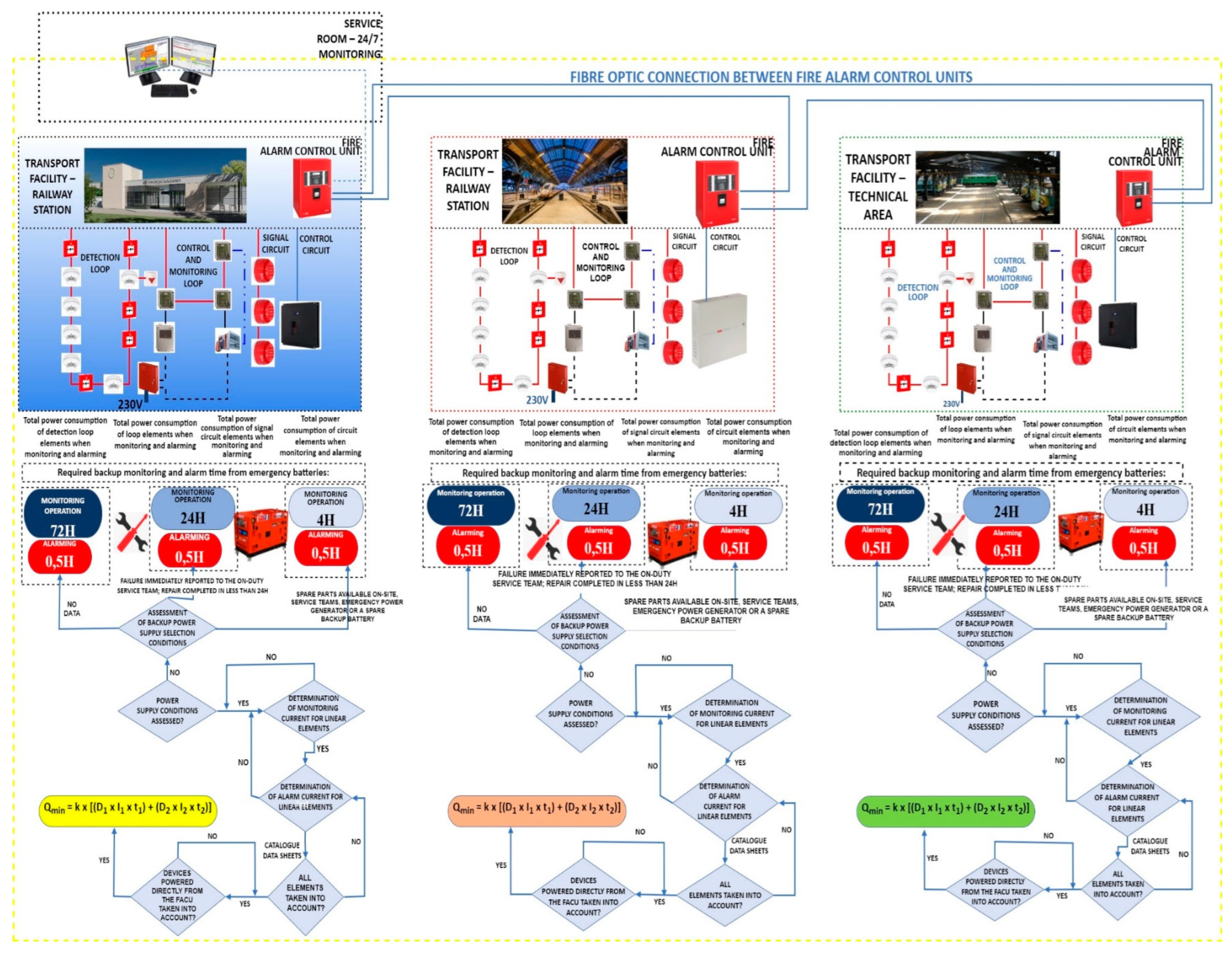
  • A concentrated FAS, with the simplest functional structure, where detection circuits and loops with sensors detecting characteristic fire features always start and terminate in an FACU;
  • Scattered FAS, of a complex functional structure. Depending on building volume [m3] or the size of a vast area [km2], such a system has from two to more than ten or several dozen FACUs. Organization, developing a fire scenario, and control matrix for all FAS elements is very complex and based on the use of dedicated computer applications. FACUs may be connected in a single loop, star, or bus with a double transmission line (optical fibre), since they have to meet specific reliability requirements [92,93,94]. A scattered system always has a master FACU, with others in slave mode. Detection loops must always start and terminate in a single fire alarm control unit;
  • A mixed-structure FAS is a combination of two aforementioned functional structures, concentrated and scattered. Usually, concentrated FAS within such a solution implements fire protection for the most fire-endangered facilities-fuel storages, archives, museums, etc.
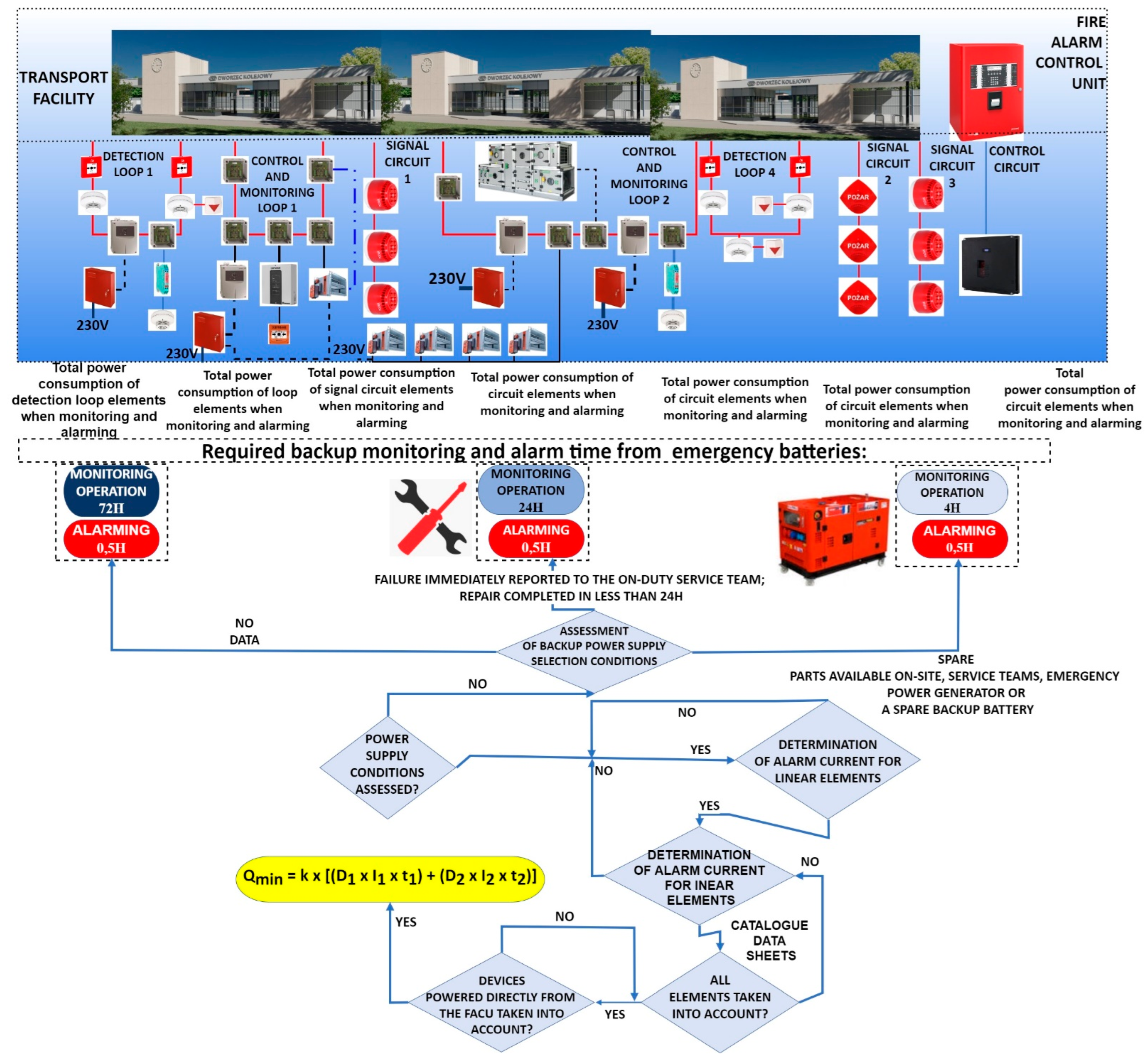
Figure 3 shows a concentrated FAS energy balance determination graph. FAS is used over a vast transport area; however, it implements the fire monitoring of several low-volume structures, which is why it has such a technical organization. It has two detection and control loops with detectors and control-monitoring devices monitoring the technical state of technical and fire-safety elements integrated with the FAS. It has two circuits equipped with audio-optical signalling and control devices. The 230 V power supply connected to the FACU, which is the power source for all elements and instruments along detection loops and circuits. The developed graph takes into account various times of detection operation, from 72, through 24 to 4 h, with separate service team availability variants. The first one (no notification and service), the second (system unfitness immediately reported to the service team via an alarm and failure signal transmission device) (AFSTD), and the third (service team available at the installed FAS location). In addition, the FAS is equipped with on-site spare part storage, a backup power generator, and a battery bank. Pursuant to the applicable legal standard, the alarm time for the energy balance determination cases in question is 0.5 h everywhere. Figure 4 shows a scattered FAS energy balance determination graph. A scattered FAS consists of three control units connected in a loop. The FACU is the master unit, while the two other ones operate as slaves. Control, monitoring, and diagnostics of a scattered FAS, as shown in Figure 4, is possible from any FACU, after logging in (in service mode) to one of the units operating in a double loop (optical fibre) for reliability reasons.
Scattered FAS is supplied with electricity through a separate internal power supply circuit from the central point connected to the building already upstream of the fire switch located inside the protected building, the so-called power supply upstream of the building’s fire-safety circuit breaker. The main electrical power switch enables de-energizing all consumers located within the protected building in order to enable a safe extinguishing operation for the fire service [94,95,96]. However, an FAS is still supplied during fire extinguishing, which is enabled by special power supply cables used only for these systems. In order to increase power supply reliability and reduce voltage drops (extensive supply cable lengths) experienced within power supply circuits, and hence, reduce the economic costs associated with the implementation of this project, each FAS usually has its own separate battery bank monitored by FAS anti-tampering contracts against unauthorized opening. An energy balance is calculated for each scattered FAS functional structure. It takes into account two technical states: monitoring and alarm. Each individual FAS of the scattered structure should be able to function for a specified operation time related to its intended use within a given building or over a vast area. Expressions for calculating the energy balance for such FAS are shown in Figure 4. The k coefficient found in the formula is the so-called reserve coefficient, which expresses redundant battery capacity during the calculations. It usually takes a value equal to 1.25 [1,94]. All FACUs have their own, extensive and stabilized power supplies supervised by microprocessor systems in terms of output currents and voltages [96,97,98]. There are additional filters inside the power supply, which eliminate interference occurring within a power mains-e.g., harmonics [94,99,100]. In addition, a power supply is equipped with overvoltage systems and filters reducing interference associated with ensuring FAS electromagnetic compatibility [96,101,102]. Unfitness or lack of main power supply is reported to an alarm-receiving-centre or service groups as a fail-safe (at that time, the system switches to backup power, e.g., from a battery bank) [96,103,104,105]. Only alarm (fire event within a facility) and failure (system unfit over a specified area) signals are sent to the State Fire Service via two independent teletransmission channels, to make sure the information reaches the recipient [1,106,107]. In order to present the entire power supply aspect—i.e., calculate the energy balance—the authors developed Figure 4. Due to the substantial amount of information that requires consideration in this Figure, some explanations may be poorly legible in this figure size; however, the authors could not omit explanations associated with the energy balance, which is a fundamental issue related to FAS functioning.
Figure 5 shows a mixed fire alarm system energy balance determination graph.
Correct FAS energy balance calculation assumes FAS operational efficiency under normal and emergency operation, i.e., after a basic power failure or in the FACU alarm state. The conducted operational tests involving selected FAS confirmed the presence of obvious errors made by the designers of such systems [1,94,96]. The most frequent mistakes in the course of FAS backup power current balance calculations include:
(1)
incorrect power consumption readings for individual devices in the monitoring and alarm states,
(2)
incorrect assumptions of the total device number (undershot or overshot),
(3)
failure to consider all devices connected to the FAS in the current balance,
(4)
overshooting detection loop or circuit current load,
(5)
erroneous assumptions in terms of the required system backup time during monitoring and alarm (i.e., oversizing or undersizing the required backup battery capacity) [2,11,68,94],
(6)
assuming an excessive battery bank capacity for a given fire alarm control unit supporting a limited capacity, as per the manufacturer’s declarations and the operation and maintenance manual [1,17,67,94].
Errors made in the course of designing systems should be distinguished from the irregularities resulting from the FAS operation process [94,96]. Based on the conducted tests, the authors of the article believe the most common operational errors encountered in the course of FAS operation, which impact the FACU current balance to be:
(1)
replacing a detector with a new one, with greater consumption of power from a detection loop or circuit,
(2)
replacing signalling devices with ones exhibiting increased power consumption,
(3)
extending detection loops at the expansion stage [2,44],
(4)
the impact of electromagnetic interference previously unconsidered in the design, which occurs within the internal and external environment [11,108,109].

4. Operation Process Analysis for a Selected FAS Operated in CI Facilities

In the age of rapid technological progress and constant technical development, CI facilities are exposed to numerous hazards [1,12,110]. These include fire that may be a direct consequence of a terrorist attack. This is why the correct protection of CI facilities using active and passive fire safety equipment is an important issue -Figure 1. Active fire protection found in CI facilities is, among others, a fire alarm system and a fixed extinguishing device (FED). Satisfying this requirement means ensuring reliable FAS functioning at all fire stages and during the extinguishing operation, i.e., detecting the fire, signalling, actuation of suppression systems, and other fire-safety systems [1,110,111]. Therefore, appropriately configured and reliable FAS must be used to ensure the technical security of CI facilities. When operating FAS in CI facilities with a very high reliability and availability index, we provide an adequate fire safety level [7,112,113,114]. It is particularly important in public utility CI facilities. Figure 6 shows an example of an FAS structure operated in a CI building. The fire-safety system includes a gravitational smoke exhaust system installed in the staircase. An FAS FACU is coupled with a smoke exhaust control unit. The smoke exhaust control unit is incorporated into an FAS detection loop via an I&C module (I/O). The loop detects fire phenomena (Figure 6) for the entire staircase located in the CI building. Fire is detected in the smoke exhaust system by detectors located within the FAS detection loop. The detectors were assigned to a detection zone in accordance with the fire scenario and control matrix for the staircase [1,69,73,115]. The activation of a smoke exhaust control unit leads to the operation of the smoke damper, i.e., its opening and opening of the aeration door on the ground floor of the CI facility staircase.
By conducting a functional analysis for a selected FAS, it is possible to illustrate the safety relationships occurring therein, in terms of reliability and operation, as presented in Figure 7. The S0 state of full fitness is a state, in which an FAS correctly implements its functions associated with fire detection. The SZB safety hazard state (e.g., QZBD1; QZBD2; …; QZBDn−1; QZBD21; QZBD22; …; QZSD;QZBS;QZB1) is a state, in which an FAS partially executes its functions associated with detection, fire scenario implementation, and control. The SB safety unreliability state is a state, in which an FAS does not execute its functions arising from the fire scenario and control. If an FAS remains in the S0 state of full fitness and experiences failures of individual devices or elements installed within detection loops or circuits, the system switches to the safety hazard state: SS (signalling circuit), SD1, SD2, SD3,…,(detection loop No. 1); SD1, SD1,…, (detection loop No. 2) and the smoke exhaust system SZSD, SB1. FAS in the state of SZB safety hazard can switch to the S0 state of full fitness upon restoring all relationships and functions implemented by the FAS (recovery, repair, and replacement of system element and devices with and intensity of µ-ignalling circuit µS1; detection loop No. 1-µD1, µD2, …; detection loop No. 2 -µD21, µD22, …; and the smoke exhaust system µKB1, µRDZSD, respectively). The QB FAS safety unreliability in the case of all detection loops and circuits being unfit leads to the inability to implement functions arising from the fire control matrix. On the other hand, switching from the SB state of safety unreliability to the S0 state of full fitness for FAS takes place when all functions arising from a control matrix developed for a given fire scenario are restored (recovery of individual system devices or elements). For the sake of better clarity, Figure 7 shows separate transitions resulting from λ damage intensities and µ recovery intensities for individual detection circuits and loops of the FAS in question. Detection loop No. 2 takes into account two detectors functioning within the smoke exhaust zone, while the smoke exhaust system takes into account mechanical assemblies such as the motorized smoke damper and a separate smoke exhaust button (marked in Figure 6).
An FAS cooperating with a smoke exhaust control unit shown in Figure 6 has been described by the following system of Kolmogorov-Chapman Equation (1):
R 0 ( t ) = λ C S P · R 0 ( t ) λ D 1 · R 0 ( t ) λ D 21 · R 0 ( t ) λ Z S D · R 0 ( t ) + μ C S P · Q B ( t ) + μ S · Q Z B S ( t ) + μ D 1 · Q Z B D 1 ( t ) + μ D 21 · Q Z B D 21 ( t ) + μ Z S D · Q Z S D ( t ) Q Z B S ( t ) = λ S 1 · Q Z B S ( t ) μ S · Q Z B S ( t ) + λ S · R 0 ( t ) + μ S 1 · Q B ( t ) Q Z B D 1 ( t ) = λ D 2 · Q Z B D 1 ( t ) μ D 1 · Q Z B D 1 ( t ) + λ D 1 · R 0 ( t ) + μ D 2 · Q Z B D 2 ( t ) Q Z B D 2 ( t ) = λ D n 1 · Q Z B D 2 ( t ) μ D 2 · Q Z B D 2 ( t ) + λ D 2 · Q Z B D 1 ( t ) + μ D n 1 · Q Z B D n 1 ( t ) Q Z B D n 1 ( t ) = λ D · Q Z B D n 1 ( t ) μ D n 1 · Q Z B D n 1 ( t ) + λ D n 1 · Q Z B D 2 ( t ) + μ D · Q B ( t ) Q Z B D 21 ( t ) = λ D 22 · Q Z B D 21 ( t ) μ D 21 · Q Z B D 21 ( t ) + λ D 21 · R 0 ( t ) + μ D 22 · Q Z B D 22 ( t ) Q Z B D 22 ( t ) = λ D 23 · Q Z B D 22 ( t ) μ D 22 · Q Z B D 22 ( t ) + λ D 22 · Q Z B D 21 ( t ) + μ D 23 · Q Z B D 23 ( t ) Q Z B D 23 ( t ) = λ D 2 n 1 · Q Z B D 23 ( t ) λ d z · Q Z B D 23 ( t ) μ D 23 · Q Z B D 23 ( t ) + λ D 23 · Q Z B D 22 ( t ) + μ D 2 n 1 · Q Z B D 2 n 1 ( t ) + μ d z · Q B 1 ( t ) Q Z S D ( t ) = λ K · Q Z S D ( t ) λ R D · Q Z S D ( t ) μ Z S D · Q Z S D ( t ) + λ Z S D · R 0 ( t ) + μ K · Q B 1 ( t ) + μ R D · Q B 1 ( t ) Q B 1 ( t ) = λ B 1 · Q B 1 ( t ) μ K · Q B 1 ( t ) μ R D · Q B 1 ( t ) μ d z · Q B 1 ( t ) + λ d z · Q Z B D 23 ( t ) + λ K · Q Z S D ( t ) + λ R D · Q Z S D ( t ) + μ B 1 · Q B ( t ) Q B ( t ) = μ C S P · Q B ( t ) μ S 1 · Q B ( t ) μ D · Q B ( t ) μ D 20 · Q B ( t ) μ B 1 · Q B ( t ) + λ C S P · R 0 ( t ) + λ S 1 · R 0 ( t ) + λ D · Q Z B D n 1 ( t ) + λ D 20 · Q Z B D 2 n 1 ( t ) + λ B 1 · Q B 1 ( t )
If we assume the following baseline conditions for further analysis (2):
R 0 ( 0 ) = 1 Q Z B S ( 0 ) = Q Z B D 1 ( 0 ) = Q Z B D 2 ( 0 ) = Q Z B D n 1 ( 0 ) = Q Z B D 21 ( 0 ) = Q Z B D 22 ( 0 ) = Q Z B D 23 ( 0 ) = Q Z B D 2 n 1 ( 0 ) = Q Z S D ( 0 ) = Q B 1 ( 0 ) = Q B ( 0 ) = 0
where:
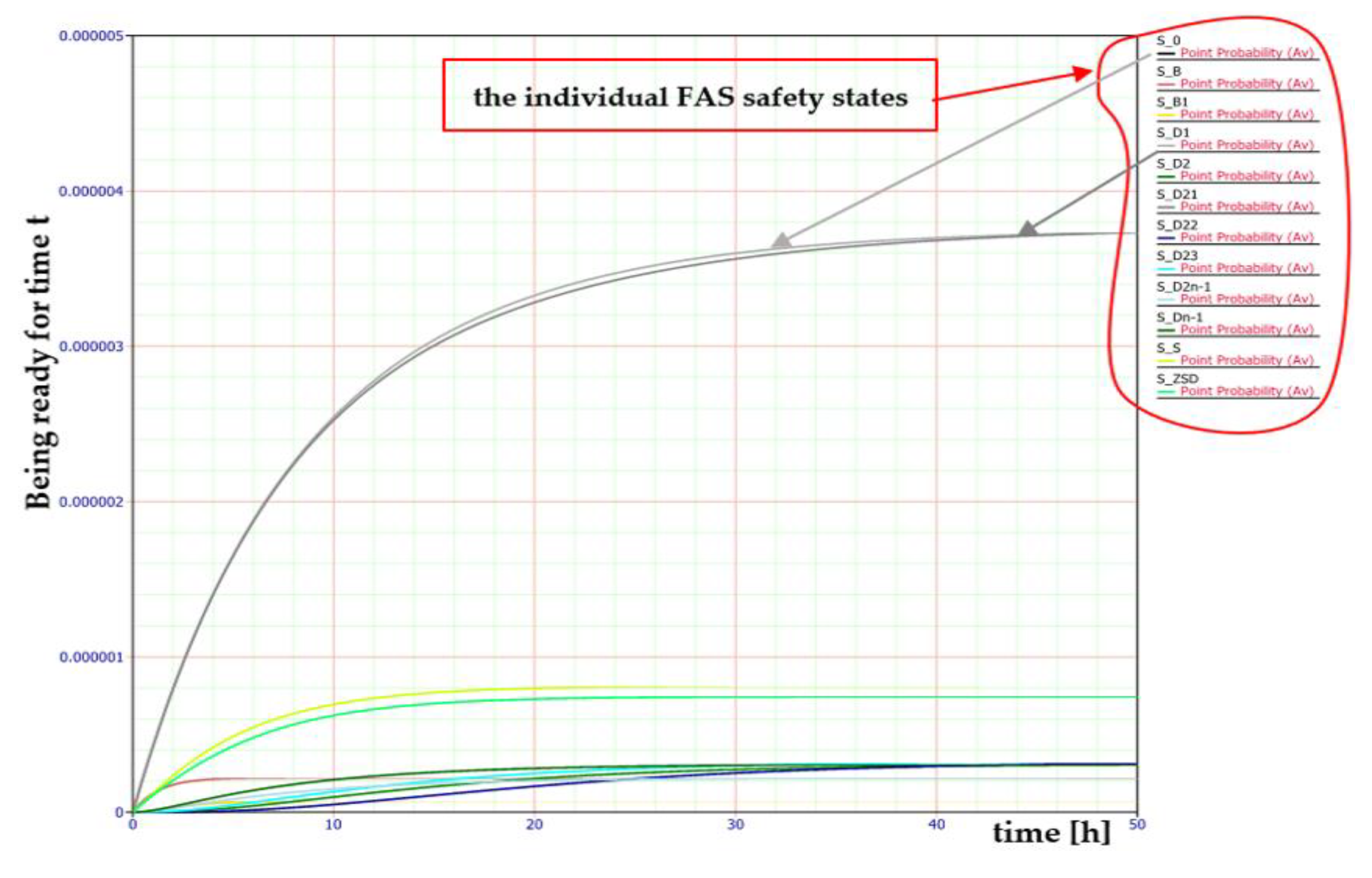
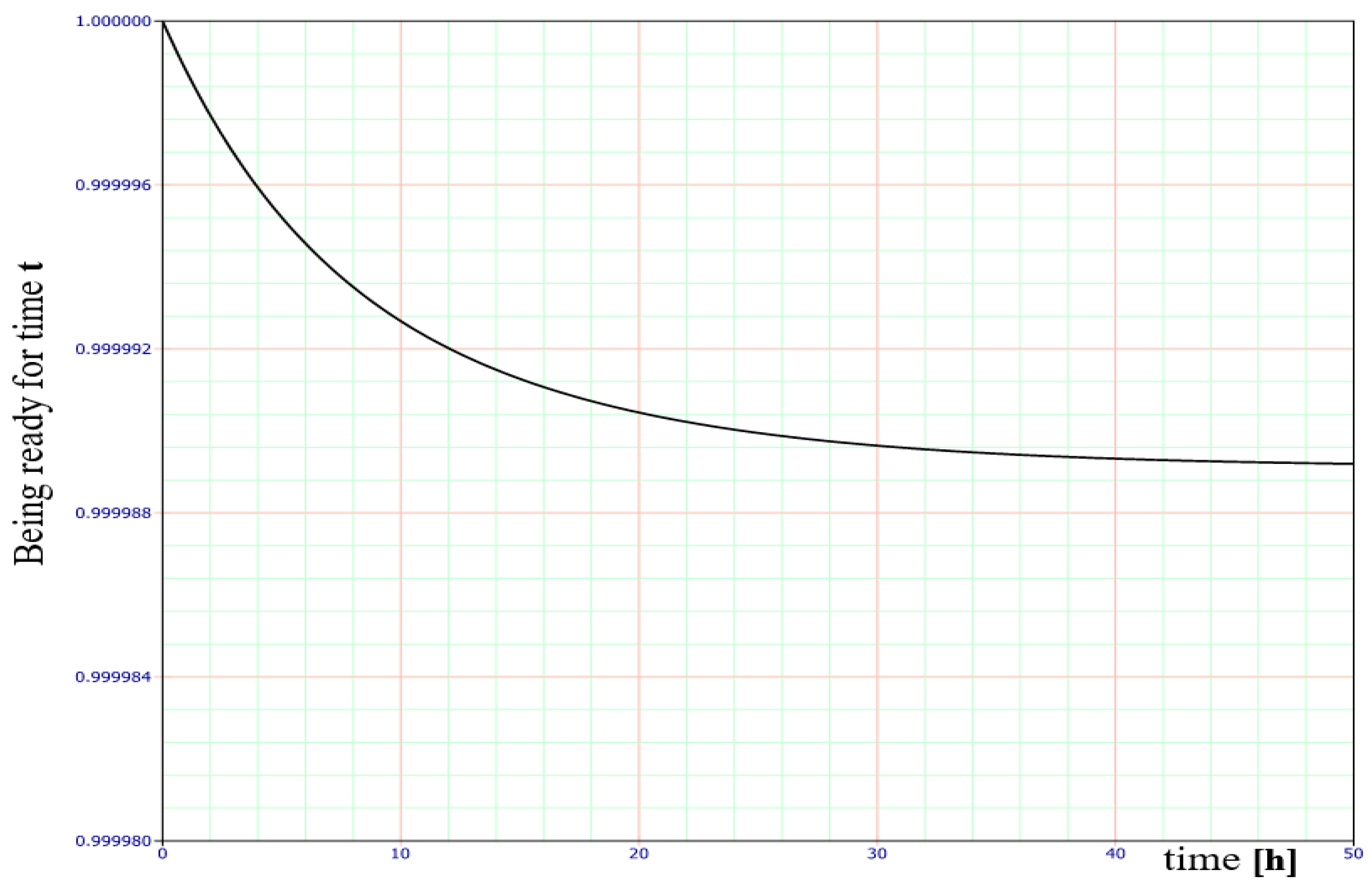
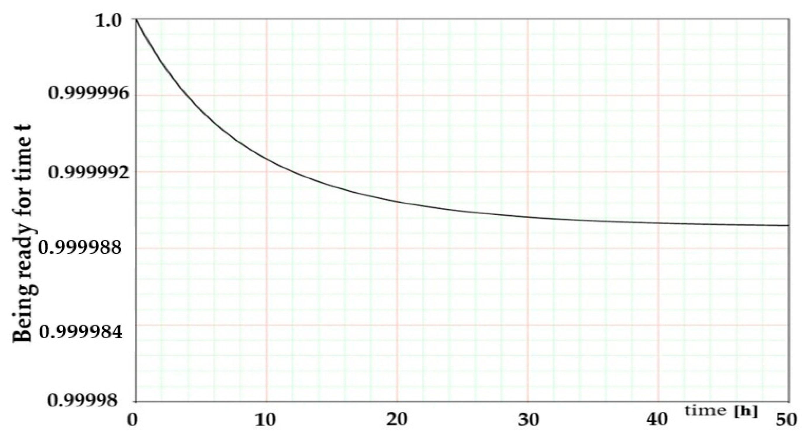
  • R0(t) is the probability function of the system staying in the SPZ state of full fitness;
  • QZBS(t), QZBD1(t), QZBD2(t), QZBDn−1(t), QZBD21(t), QZBD22(t), QZBD23(t), QZBD2n−1(t), QZSD(t), QB1(t) are the probability function for FAS staying in individual safety hazard states;
  • QB(t) is the probability function of the system staying in the SB state of safety unreliability;
  • λCSP is the intensity of transition from the SPZ state of full fitness to SB the state of safety unreliability;
  • µCSP is the intensity of transition from the SB state of safety unreliability to the SPZ state of full fitness;
  • λS1, λD, … are the intensity of transitions from the SPZ state of full fitness, the SZB state of the safety hazard, or the SZB state of safety unreliability-n accordance with designations in Figure 7;
  • µS1, µD2, … is the intensity of transitions from the SZB state of the safety hazard to the SPZ state of full fitness, and the state of safety unreliability to the state of safety hazard–in accordance with designations in Figure 7.
And then, after applying the Laplace transform, we have a system of linear equations
s · R 0 * ( s ) 1 = ( λ C S P + λ D 1 + λ D 21 + λ Z S D ) · R 0 * ( s ) + μ C S P · Q B * ( s ) + μ S · Q Z B S * ( s ) + μ D 1 · Q Z B D 1 * ( s ) + μ D 21 · Q Z B D 21 * ( s ) + μ Z S D · Q Z S D * ( s ) s · Q Z B S * ( s ) = ( λ S 1 + μ S ) · Q Z B S * ( s ) + λ S · R 0 * ( s ) + μ S 1 · Q B * ( s ) s · Q Z B D 1 * ( s ) = ( λ D 2 + μ D 1 ) · Q Z B D 1 * ( s ) + λ D 1 · R 0 * ( s ) + μ D 2 · Q Z B D 2 * ( s ) s · Q Z B D 2 * ( s ) = ( λ D n 1 + μ D 2 ) · Q Z B D 2 * ( s ) + λ D 2 · Q Z B D 1 * ( s ) + μ D n 1 · Q Z B D n 1 * ( s ) s · Q Z B D n 1 * ( s ) = ( λ D + μ D n 1 ) · Q Z B D n 1 * ( s ) + λ D n 1 · Q Z B D 2 * ( s ) + μ D · Q B * ( s ) s · Q Z B D 21 * ( s ) = ( λ D 22 + μ D 21 ) · Q Z B D 21 * ( s ) + λ D 21 · R 0 * ( s ) + μ D 22 · Q Z B D 22 * ( s ) s · Q Z B D 22 * ( s ) = ( λ D 23 + μ D 22 ) · Q Z B D 22 * ( s ) + λ D 22 · Q Z B D 21 * ( s ) + μ D 23 · Q Z B D 23 * ( s ) s · Q Z B D 23 * ( s ) = ( λ D 2 n 1 + λ d z + μ D 23 ) · Q Z B D 23 * ( s ) + λ D 23 · Q Z B D 22 * ( s ) + μ D 2 n 1 · Q Z B D 2 n 1 * ( s ) + μ d z · Q B 1 * ( s ) s · Q Z S D * ( s ) = ( λ K + λ R D + μ Z S D ) · Q Z S D * ( s ) + λ Z S D · R 0 * ( s ) + μ K · Q B 1 * ( s ) + μ R D · Q B 1 * ( s ) s · Q B 1 * ( s ) = ( λ B 1 + μ K + μ R D + μ d z ) · Q B 1 * ( s ) + λ d z · Q Z B D 23 * ( s ) + λ K · Q Z S D * ( s ) + λ R D · Q Z S D * ( s ) + μ B 1 · Q B * ( s ) s · Q B * ( s ) = ( μ C S P + μ S 1 + μ D + μ D 20 + μ B 1 ) · Q B * ( s ) + λ C S P · R 0 * ( s ) + λ S 1 · R 0 * ( s ) + λ D · Q Z B D n 1 * ( s ) + λ D 20 · Q Z B D 2 n 1 * ( s ) + λ B 1 · Q B 1 * ( s )
The BlockSim software was used to calculate the availability and reliability for an FAS with a smoke exhaust control unit staying in individual states, as per the assumed operating time of 8760 h, and the repair (recovery) and reliability coefficient values-in Figure 8.
Calculated values of individual availability coefficients over time, for individual safety states, as in Figure 7, for an FAS integrated with smoke exhaust and common fire detection, were conducted using statistical data collected from 20 systems operat-ed within CI facilities. For the purpose of determining the λ damage intensity and µ recovery intensity, the authors of the article divided FAS into components making up the entire system, i.e., detectors of a specific type, modules, signalling devices, etc. The aforementioned operation process coefficients were determined for individual FAS elements. All 20 FAS were operated under similar environmental conditions, with local access to servicing at the place of operation and the so-called on-site spare part stor-ages should any unfitness event occur (repair commenced immediately after obtaining information on the partial damage status from the fire alarm control unit). Due to their complexity, the computations were conducted using a BlockSim computer application by ReliaSoft. The ReliaSoft BlockSim, as a specialized computer application, provides a platform for testing system reliability, FAS in this case. Computer software enables computing FAS availability and conducting analyses in this respect. The presented computer application computations and graphs enable a conclusion that an appropri-ately designed and executed FAS exhibits a significantly high availability coefficient kg(t), e.g., for time t = 1.125 [h] kg(t) = 0.999 (Table 1). This is a consequence of the fact that individual FAS elements, devices, and base modules offer appropriate technical and system solutions that utilize redundancy and the so-called fail-safe concept. An important operational issue for FAS is related to the so-called “infant age failures (un-fitness)” that are manifested at the initial system operation stage (Figure 9). The initial FAS operation period (up to 40 h of system operation from activation-commissioning) experiences a loss in the values of the kg(t) availability coefficient. This coefficient sta-bilizes after this period at a value equal to kg(t) = 0.999-(Figure 10). Virtually the same value of the kg(t) availability coefficient is maintained for a time t = 8760 [h]. In the in-itial operation period, the predominant operational states (exhibiting the highest val-ues) of FAS are the S_0 state of full fitness (designation in Figure 9 according to the simulation software) and the S_D1 state (detection loop No. 1, detector No. 1) (Figure 9). Other operational state coefficients with respect to the FAS provided for calcula-tions and simulations reach very small values below 1·10−6 and they can be practically omitted within the process under consideration.

5. Conclusions

The issues related to the operation of fire alarm systems located in critical infrastructure facilities are extremely important with respect to ensuring safety. These systems are installed and operated in accordance with applicable standards and regulations, as well as legislation, which require FAS monitoring in strictly defined buildings. Such a legal basis relative to FAS entails the high reliability of these systems. FAS installed in critical infrastructure facilities require continuous supervision of service teams and the existence of “on-site spare part storages” to ensure the shortest possible repair (recovery) time. This solution for the operation process leads to a very low µ recovery intensity, in other words, the repair time in the event of unfitness is very short. The repair (recovery) time during the research conducted by the authors of the article varied, e.g., FAS power supply failure resulted in a maximum repair time of 15 min. However, there were also FAS unfitness events when the repair time took hours, e.g., repairing the unfitness of a detector in the detection loop No. 2/55, reported to the FACU as a “not responding-communication error” malfunction took 4 [h], and replacing batteries with new ones on the backup power supply takes precisely 13 h 10 min; or the communication (signal transmission) error in loop No. 1-repair time of 4 [h], involving appropriate tie-in of loop No. 1 cabling to FACU terminals. Due to the process of operating FAS in CI facilities, some times associated with repair/recovery are acceptable and some are not, due to being longer. In such a case, the whole system or a part of it fails to monitor fire safety within a facility. FAS, and especially an FACU that is responsible for implementing the process of diagnosing complex-scattered or mixed-system are fitted with an extensive module(s) intended solely for this type of operation, i.e., implementing this process only. Diagnostic modules detect “simple” malfunctions, such as a detection circuit/loop resistance change or shorting/opening but also such failures as a detector replaced with a different type, control unit-detector(s)/module(s) digital communication errors, or intentional sabotage—e.g., element removal. The FAS diagnosis process is implemented continuously by the FACU, concurrently with the fundamental operation type-monitoring. However, an alarm signal has higher priority in the FACU, and in the event of any such signal, the control unit automatically suspends the FAS diagnosis process. Such a solution in relation to FAS causes information on system unfitness to be continuously transmitted to services residing within CI facilities, which significantly shortens intervention time in the event of a failure. FAS energy balance calculations should take into account the different functional structures of the systems. This is why three independent graphs were developed as part of the article. A separate energy balance that takes into account the internal connection structure should be developed for each subsystem (slave) of a scattered FAS.
The next stage of the article focused on developing an operation process model for a selected FAS operated in CI facilities. Based on the conducted computer simulation, the FAS is characterized by high reliability in the order of R = 0.989 after one year of operation under given environmental conditions. No complete failure of the FAS was identified based on the conducted actual operational tests and a reading taken from the “event log” stored in the FAS non-volatile memory. FAS reliability structures do not include the so-called “critical paths”, where a failure of one element or device leads to the unfitness of the entire system. A FACU is an element critical for all FAS for reliability reasons. However, all FACUs in CI facilities exhibited 100% redundancy. The second alarm control unit was operated as a “hot” unloaded backup. No case of a complete FACU failure was identified in the course of the tests. The conducted tests allow users and persons employed in FAS service departments to have information on system reliability. In addition to technical aspects, such a high FAS reliability is also important from the legal perspective of the operation process. FAS are the only electronic security systems, the functioning of which in buildings is legally assented.
Conducted computer simulations confirm also an important practical aspect of the conducted research and scientific considerations discussed herein. Appropriate technical service organization, functioning of the spare part storage within a given facility, adequate failure response time, and the application of all available technical solutions with respect to improving reliability enabled achieving such a high system availability coefficient. In their further research, the authors plan to conduct operational tests of FAS operated in other facilities, not classified as CI. The authors also plan to conduct operational tests involving other electronic security systems operated in smart buildings, CI, and single-family houses.

Author Contributions

Conceptualization, T.K., J.P. and S.D.; methodology, J.P. and T.K.; validation, T.K., J.P. and M.M.; formal analysis, T.K., J.P., A.R. and S.D.; investigation, J.P., T.K., A.R., P.W. and K.B.; resources, T.K. and J.P.; data curation, T.K., M.M. and J.P.; writing—original draft preparation, T.K., J.P., A.R. and M.M.; writing—review and editing, J.P. and T.K.; visualization, T.K., P.W., K.B. and J.P.; supervision, J.P. and T.K.; project administration, M.M. and J.P.; funding acquisition, J.P., A.R. and T.K. All authors have read and agreed to the published version of the manuscript.

Funding

This work was financed/co-financed by the Military University of Technology under research project UGB 737. This paper was co-financed under the research grant of the Warsaw University of Technology supporting scientific activity in the discipline of Civil Engineering and Transport.

Institutional Review Board Statement

Not applicable.

Informed Consent Statement

Not applicable.

Data Availability Statement

The data presented in this study are available on request from the corresponding author.

Conflicts of Interest

The authors declare no conflict of interest.

Nomenclature

FAS Fire Alarm System,
FACUFire Alarm Control Unit,
ESSElectronic Security Systems
CI Critical Infrastructure
kg(t)availability coefficient,
µrecovery intensity coefficient,
λdamage intensity coefficient,
RO(t)probability function of an FAS staying in the SPZ state (full fitness)
QZB(t)probability function of an FAS staying in the SZB state (safety hazard)
QB(t)probability function of an FAS staying in the SPZ state (safety unreliability)
λZB1damage intensity, transition of a selected FAS from the SPZ state to the SZB state,
μPZ1recovery intensity, transition from the SZB state to the SPZ state,
MCPManual Call Point
AWSAudio Warning System
SSsignalling circuit,
SD1detection loop No. 1,
λCSPintensity of transition from the SPZ state of full fitness to the SB state of safety unreliability;
AFSTDalarm and failure signal transmission device
FEDfixed (fire) extinguishing device
kmargin coefficient for energy balance calculations,
TF1–TF9test fire designations,
ABPSautomatic backup power switch,
SSWiNSystemu Sygnalizacji Włamania i Napadu,
PIRPassive Infra-Red,
ACSAccess Control Systems,
CCTV Closed-circuit TV,
ABPS Automatic Backup Power Switch wymuszenia zakłócające,
AWSAudio Warning system
Kreserve coefficient, usually taken as 1.25
I1determined FAS power consumption in the technical state of monitoring for the first fire system,
t1required operating time of the FAS in the technical state of alarm,
I2determined FAS power consumption in the technical state of alarm,
t2required FAS operating time in the technical state of alarm,
D2coefficient associated with reduced battery capacity resulting, from drawing large-value power under alarm conditions

References

  1. Klimczak, T.; Paś, J. Basics of Exploitation of Fire Alarm Systems in Transport Facilities; Military University of Technology: Warsaw, Poland, 2020. [Google Scholar]
  2. Klimczak, T.; Paś, J. Selected issues of the reliability and operational assessment of a fire alarm system. Eksploat. Niezawodn. Maint. Reliab. 2019, 21, 553–561. [Google Scholar] [CrossRef]
  3. Frangopol, D.M.; Liu, M. Maintenance and management of civil infrastructure based on condition, safety, optimization, and lifecycle cost. Struct. Infrastruct. Eng. 2007, 3, 29–41. [Google Scholar] [CrossRef]
  4. Kołowrocki, K.; Soszyńska-Budny, J. Critical Infrastructure Safety Indicators. In Proceedings of the IEEE International Conference on Industrial Engineering and Engineering Management (IEEM), Bangkok, Thailand, 16–19 December 2018; pp. 1761–1764. [Google Scholar] [CrossRef]
  5. Government Security Center. National Critical Infrastructure Protection Programme in Poland. Rev. 08.2020. Available online: https://www.gov.pl/attachment/ee334990-ec9c-42ab-ae12-477608d94eb1 (accessed on 18 August 2021).
  6. Jafari, M.J.; Pouyakian, M.; Khanteymoori, A.; Hanifi, S.M. Reliability evaluation of fire alarm systems using dynamic Bayesian networks and fuzzy fault tree analysis. J. Loss Prev. Process Ind. 2020, 67, 104229. [Google Scholar] [CrossRef]
  7. Rosiński, A. Modelling the Maintenance Process of Transport Telematics Systems; Publishing House Warsaw University of Technology: Warsaw, Poland, 2015. [Google Scholar]
  8. Regulation of Ministry of the Interior and Administration of Poland (MSWiA) of 7 June 2010 (Journal of Laws of the Republic of Poland No. 109, Item 719) Concerning Fire Protection of Buildings and Other Facilities and Grounds; Ministry of the Interior and Administration of Poland: Warsaw, Poland, 2021. Available online: https://sip.lex.pl/akty-prawne/dzu-dziennik-ustaw/ochronaprzeciwpożarowa-budynkow-innych-obiektow-budowlanych-i-terenow-17626053 (accessed on 17 November 2021).
  9. Andrzejczak, K.; Bukowski, L. A method for estimating the probability distribution of the lifetime for new technical equipment based on expert judgement. Eksploat. Niezawodn. Maint. Reliab. 2021, 23, 757–769. [Google Scholar] [CrossRef]
  10. Migdalski, J. Reliability Engineering—A Handbook; ATR: Bydgoszcz, Poland, 1992. [Google Scholar]
  11. Pas, J.; Rosinski, A.; Chrzan, M.; Bialek, K. Reliability-operational analysis of the LED lighting module including electromagnetic interference. IEEE Trans. Electromagn. Compat. 2020, 62, 2747–2758. [Google Scholar] [CrossRef]
  12. Paś, J.; Rosiński, A.; Białek, K. A reliability-operational analysis of a track-side CCTV cabinet taking into account interference. Bull. Pol. Acad. Sci. Tech. Sci. 2021, 69, e136747. [Google Scholar] [CrossRef]
  13. Gupta, S.; Kanwar, S.; Kashyap, M. Performance characteristics and assessment of fire alarm system. Mater. Today Proc. 2022, 57, 2036–2040. [Google Scholar] [CrossRef]
  14. Pati, V.B.; Joshi, S.P.; Sowmianarayana, R.; Vedavathi, M.; Rana, R.K. Simulation of Intelligent Fire Detection and Alarm System for a Warship. Def. Sci. J. 1989, 39, 79–94. [Google Scholar] [CrossRef] [Green Version]
  15. Keding, L. An optimization of intelligent fire alarm system for high-rise building based on ANASYS. In Intelligence Computation and Evolutionary Computation; Du, Z., Ed.; Springer: Berlin/Heidelberg, Germany, 2013; pp. 415–421. [Google Scholar] [CrossRef]
  16. Østrem, L.; Sommer, M. Inherent fire safety engineering in complex road tunnels—Learning between industries in safety management. Saf. Sci. 2021, 134, 105062. [Google Scholar] [CrossRef]
  17. Hulida, E.; Pasnak, I.; Koval, O.; Tryhuba, A. Determination of the Critical Time of Fire in the Building and Ensure Successful Evacuation of People. Period. Polytech. Civ. Eng. 2019, 63, 308–316. [Google Scholar] [CrossRef]
  18. Dziula, P.; Paś, J. Low Frequency Electromagnetic Interferences Impact on Transport Security Systems Used in Wide Transport Areas. TransNav Int. J. Mar. Navig. Saf. Sea Transp. 2018, 12, 251–258. [Google Scholar] [CrossRef] [Green Version]
  19. Siergiejczyk, M.; Paś, J.; Dudek, E. Reliability analysis of aerodrome’s electronic security systems taking into account electromagnetic interferences. In Safety and Reliability—Theory and Applications, Proceedings of the 27th European Safety and Reliability Conference (Esrel 2017), Portorož, Slovenia, 18–22 June 2017; Cepin, M., Briš, R., Eds.; CRC Press/Balkema: Schipholewh, The Netherlands, 2017; pp. 2285–2292. [Google Scholar]
  20. Burdzik, R.; Konieczny, Ł.; Figlus, T. Concept of on-board comfort vibration monitoring system for vehicles. In Proceedings of the Communications in Computer and Information Science, Activities of Transport Telematics 13th International Conference on Transport Systems Telematics, TST 2013, Katowice-Ustron, Poland, 23–26 October 2013; Mikulski, J., Ed.; Springer: Berlin/Heidelberg, Germany, 2013; Volume 395, pp. 418–425. [Google Scholar]
  21. Żółtowski, B.; Niziński, S. Modeling of Machine Exploitation Processes; Markar: Bydgoszcz, Poland, 2002. [Google Scholar]
  22. Duer, S. Examination of the reliability of a technical object after its regeneration in a maintenance system with an artificial neural network. Neural Comput. Appl. 2012, 21, 523–534. [Google Scholar] [CrossRef]
  23. Suproniuk, M.; Paś, J. Analysis of electrical energy consumption in a public utility buildings. Przegl Elektrotechniczny 2019, 95, 97–100. [Google Scholar] [CrossRef]
  24. Krzykowski, M.; Paś, J.; Rosiński, A. Assessment of the level of reliability of power supplies of the objects of critical infrastructure. IOP Conf. Ser. Earth Environ. Sci. 2019, 214, 012018. [Google Scholar] [CrossRef]
  25. Vasile, D.-C.; Svasta, P.; Pantazica, M. Preventing the Temperature Side Channel Attacks on Security Circuits. In Proceedings of the 2019 IEEE 25th International Symposium for Design and Technology in Electronic Packaging (SIITME), Cluj-Napoca, Romania, 23–26 October 2019; IEEE: Piscataway Township, NJ, USA, 2019; pp. 244–247. [Google Scholar]
  26. Chung, I.-H.; Lin, Y.-H. Exploring the Impact of Parallel Architecture on Improving Adaptable Neuro-Fuzzy Inference Systems for Gas-Insulated Switch Defect Recognition. Energies 2022, 15, 3940. [Google Scholar] [CrossRef]
  27. Zhao, H.; Schwabe, A.; Schläfli, F.; Thrash, T.; Aguilar, L.; Dubey, R.K.; Karjalainen, J.; Hölscher, C.; Helbing, D.; Schinazi, V.R. Fire evacuation supported by centralized and decentralized visual guidance systems. Saf. Sci. 2022, 145, 105451. [Google Scholar] [CrossRef]
  28. Shaw, E.; Roper, T.; Nilsson, T.; Lawson, G.; Cobb, S.V.; Miller, D. The heat is on: Exploring user behaviour in a multisensory virtual environment for fire evacuation. In Proceedings of the 2019 CHI Conference on Human Factors in Computing Systems, Glasgow, Scotland, 4–9 May 2019; pp. 1–13. [Google Scholar]
  29. Fridolf, K.; Nilsson, D.; Frantzich, H. Fire Evacuation in Underground Transportation Systems: A Review of Accidents and Empirical Research. Fire Technol. 2013, 49, 451–475. [Google Scholar] [CrossRef]
  30. Foggia, P.; Saggese, A.; Vento, M. Real-time fire detection for video-surveillance applications using a combination of experts based on color shape and motion. IEEE Trans. Circuits Syst. Video Technol. 2015, 25, 1545–1556. [Google Scholar] [CrossRef]
  31. Rahman, M.A.; Hasan, S.T.; Kader, M.A. Computer Vision Based Industrial and Forest Fire Detection Using Support Vector Machine (SVM). In Proceedings of the 2022 International Conference on Innovations in Science, Engineering and Technology (ICISET), Chittagong, Bangladesh, 26–27 February 2022; pp. 233–238. [Google Scholar] [CrossRef]
  32. Ding, L.; Khan, F.; Ji, J. Risk-based safety measure allocation to prevent and mitigate storage fire hazards. Process Saf. Environ. Prot. 2020, 135, 282–293. [Google Scholar] [CrossRef]
  33. Derbel, F. Performance improvement of fire detectors by means of gas sensors and neural networks. Fire Saf. J. 2004, 39, 383–398. [Google Scholar] [CrossRef]
  34. Liu, F.; Liu, Y.; Xiong, K.; Weng, M.; Wang, J. Experimental and numerical study on the smoke movement and smoke control strategy in a hub station fire. Tunn. Undergr. Space Technol. 2020, 96, 103177. [Google Scholar] [CrossRef]
  35. Chung, I.-H. Exploring the Influence of the Parameters’ Relationship between Reliability and Maintainability for Offshore Wind Farm Engineering. Energies 2022, 15, 5610. [Google Scholar] [CrossRef]
  36. Polak, R.; Laskowski, D.; Matyszkiel, R.; Łubkowski, P.; Konieczny, Ł.; Burdzik, R. Optimizing the data flow in a network communication between railway nodes. In Research Methods and Solutions to Current Transport Problems, Proceedings of the International Scientific Conference Transport of the 21st Century, Advances in Intelligent Systems and Computing, Ryn, Poland, 9–12 June 2019; Siergiejczyk, M., Krzykowska, K., Eds.; Springer: Cham, Switzerland, 2020; Volume 1032, pp. 351–362. [Google Scholar] [CrossRef]
  37. Caban, D.; Walkowiak, T. Dependability analysis of hierarchically composed system-of-systems. In Thirteenth International Conference on Dependability and Complex Systems DepCoS-RELCOMEX; Springer: Cham, Switzerland, 2019; pp. 113–120. [Google Scholar] [CrossRef]
  38. Kołowrocki, K.; Soszyńska-Budny, J. Reliability and Safety of Complex Technical Systems and Processes: Modeling—Identification—Prediction—Optimization; Springer: London, UK, 2011. [Google Scholar] [CrossRef]
  39. Grabski, F. Semi-Markov Processes: Applications in System Reliability and Maintenance; Elsevier: Amsterdam, The Netherlands, 2015. [Google Scholar]
  40. Bogalecka, M.; Kołowrocki, K. Minimization of critical infrastructure accident losses of chemical releases impacted by climateweather change. In Proceedings of the International Conference on Industrial Engineering and Engineering Management-IEEM, Bangkok, Thailand, 16–19 December 2018. [Google Scholar] [CrossRef]
  41. Lheurette, E. (Ed.) Metamaterials and Wave Control; ISTE and Wiley: London, UK, 2013. [Google Scholar]
  42. Stawowy, M.; Perlicki, K.; Sumiła, M. Comparison of uncertainty multilevel models to ensure ITS services. In Safety and Reliability: Theory and Applications, Proceedings of the European Safety and Reliability Conference ESREL 2017, Portoroz, Slovenia, 18–22 June 2017; Cepin, M., Bris, R., Eds.; CRC Press/Balkema: London, UK, 2017; pp. 2647–2652. [Google Scholar] [CrossRef]
  43. Bednarek, M.; Dąbrowski, T.; Olchowik, W. Selected practical aspects of communication diagnosis in the industrial network. J. KONBiN 2019, 49, 383–404. [Google Scholar] [CrossRef] [Green Version]
  44. Oszczypała, M.; Ziółkowski, J.; Małachowski, J. Reliability Analysis of Military Vehicles Based on Censored Failures Data. Appl. Sci. 2022, 12, 2622. [Google Scholar] [CrossRef]
  45. Geng, X.; Wen, Y.; Zhang, J.; Zhang, D. A Method to Supervise the Effect on Railway Radio Transmission of Pulsed Disturbances Based on Joint Statistical Characteristics. Appl. Sci. 2020, 10, 4814. [Google Scholar] [CrossRef]
  46. Valouch, J. Integrated alarm systems. In Computer Applications for Software Engineering, Disaster Recovery, and Business Continuity; Series: Communications in Computer and Information Science XVIII; Springer: Berlin/Heidelberg, Germany, 2012; Volume 340, pp. 369–379. ISSN 1865-0929. [Google Scholar]
  47. Jacyna, M.; Szczepański, E.; Izdebski, M.; Jasiński, S.; Maciejewski, M. Characteristics of event recorders in Automatic Train Control systems. Arch. Transp. 2018, 46, 61–70. [Google Scholar] [CrossRef]
  48. Kornaszewski, M. Modelling of exploitation process of the railway traffic control device. WUT J. Transp. Eng. 2019, 124, 53–63. [Google Scholar] [CrossRef]
  49. Suproniuk, M.; Skibko, Z.; Stachno, A. Diagnostics of some parameters of electricity generated in wind farms. Przegląd Elektrotechniczny 2019, 95, 105–108. [Google Scholar] [CrossRef]
  50. Duer, S. Assessment of the Operation Process of Wind Power Plant’s Equipment with the Use of an Artificial Neural Network. Energies 2020, 13, 2437. [Google Scholar] [CrossRef]
  51. Scheffey, J.; Darwin, R.; Leonard, J. Evaluating Firefighting Foams for Aviation Fire Protection. Fire Technol. 1995, 31, 224–243. [Google Scholar] [CrossRef]
  52. Serio, M.A.; Bonamno, A.S.; Knight, K.S.; Newman, J.S. Fourier Transform Infrared Diagnostics for Improved Fire Detection Systems; NIST Annual Conference on Fire Research: Gaithersburg, MD, USA, 1996. [Google Scholar]
  53. Epstein, B.; Weissman, I. Mathematical Models for Systems Reliability; CRC Press/Taylor & Francis Group: Boca Raton, FL, USA, 2008. [Google Scholar]
  54. Cha, J.H.; Finkelstein, M. Point Processes for Reliability Analysis Shocks and Repairable Systems; Springer: Berlin/Heidelberg, Germany, 2018. [Google Scholar]
  55. Danish, M.; Luo, S. A New Route to Enhance the Packing Density of Buckypaper for Superior Piezoresistive Sensor Characteristics. Sensors 2020, 20, 2904. [Google Scholar] [CrossRef] [PubMed]
  56. Duer, S.; Zajkowski, K.; Harničárová, M.; Charun, H.; Bernatowicz, D. Examination of Multivalent Diagnoses Developed by a Diagnostic Program with an Artificial Neural Network for Devices in the Electric Hybrid Power Supply System “House on Water”. Energies 2021, 14, 2153. [Google Scholar] [CrossRef]
  57. Duer, S.; Duer, R.; Mazuru, S. Determination of the expert knowledge base on the basis of a functional and diagnostic analysis of a technical object. Nonconv. Technol. Rev. 2016, 20, 23–29. Available online: http://revtn.ro/index.php/revtn/article/view/115/76 (accessed on 12 August 2021).
  58. Xu, S.; Li, X. Analysis on thermal reliability of key electronic components on PCB board. In Proceedings of the 2011 Interna-tional Conference on Quality, Reliability, Risk, Maintenance, and Safety Engineering, Xi’an, China, 17–19 June 2011; Huang, H.Z., Zuo, M.J., Jia, X., Liu, Y., Eds.; IEEE: Xi’an, China, 2011; pp. 52–54. [Google Scholar]
  59. Jakubowski, K.; Paś, J.; Rosiński, A. The Issue of Operating Security Systems in Terms of the Impact of Electromagnetic Interference Generated Unintentionally. Energies 2021, 14, 8591. [Google Scholar] [CrossRef]
  60. Tooley, M.H.; Wyatt, D. Aircraft Electrical and Electronic Systems: Principles, Operation and Maintenance; Routledge: London, UK; New York, NY, USA, 2011; ISBN 978-0-7506-8695-2. [Google Scholar]
  61. Młynarski, S.; Pilch, R.; Smolnik, M.; Szybka, J.; Wiązania, G. A model of an adaptive strategy of preventive maintenance of complex technical objects. Eksploat. Niezawodn. Maint. Reliab. 2020, 22, 35–41. [Google Scholar] [CrossRef]
  62. Dziula, P.; Kołowrocki, K.; Soszyńska-Budny, J. Maritime Transportation System Safety-Modeling and Identification. TransNav Int. J. Mar. Navig. Saf. Transp. 2013, 7, 169–175. [Google Scholar] [CrossRef]
  63. Soszyńska-Budny, J. General approach to critical infrastructure safety modelling. In Safety Analysis of Critical Infrastructure. Lecture Notes in Intelligent Transportation and Infrastructure; Springer: Cham, Switzerland, 2021. [Google Scholar] [CrossRef]
  64. Paś, J.; Klimczak, T.; Rosiński, A.; Stawowy, M. The Analysis of the Operational Process of a Complex Fire Alarm System Used in Transport Facilities. Build. Simul. 2022, 15, 615–629. [Google Scholar] [CrossRef]
  65. Liu, Z.; Kim, A.K. Review of Recent Developments in Fire Detection Technologies. J. Fire Prot. Eng. 2003, 13, 129–151. [Google Scholar] [CrossRef] [Green Version]
  66. Stawowy, M.; Olchowik, W.; Rosiński, A.; Dąbrowski, T. The Analysis and Modelling of the Quality of Information Ac-quired from Weather Station Sensors. Remote Sens. 2021, 13, 693. [Google Scholar] [CrossRef]
  67. Wang, Y.; Zhang, Q.; Soutis, C.; Gresil, M. Development of a Fire Detection and Suppression System for a Smart Air Cargo Container. Aeronaut. J. 2021, 125, 205–222. [Google Scholar]
  68. Oszczypała, M.; Ziółkowski, J.; Małachowski, J. Analysis of Light Utility Vehicle Readiness in Military Transportation Systems Using Markov and Semi-Markov Processes. Energies 2022, 15, 5062. [Google Scholar] [CrossRef]
  69. Lewczuk, K.; Kłodawski, M.; Gepner, P. Energy Consumption in a Distributional Warehouse: A Practical Case Study for Different Warehouse Technologies. Energies 2021, 14, 2709. [Google Scholar] [CrossRef]
  70. Jakubowski, K.; Paś, J.; Duer, S.; Bugaj, J. Operational Analysis of Fire Alarm Systems with a Focused, Dispersed and Mixed Structure in Critical Infrastructure Buildings. Energies 2021, 14, 7893. [Google Scholar] [CrossRef]
  71. Łukasiak, J.; Rosiński, A.; Wiśnios, M. The Impact of Temperature of the Tripping Thresholds of Intrusion Detection System Detection Circuits. Energies 2021, 14, 6851. [Google Scholar] [CrossRef]
  72. Avazov, K.; Mukhiddinov, M.; Makhmudov, F.; Cho, Y.I. Fire Detection Method in Smart City Environments Using a Deep-Learning-Based Approach. Electronics 2022, 11, 73. [Google Scholar] [CrossRef]
  73. Kozłowski, E.; Borucka, A.; Swiderski, A. Application of the logistic regression for determining transition probability matrix of operating states in the transport systems. Eksploat. Niezawodn. Maint. Reliab. 2020, 22, 192–200. [Google Scholar] [CrossRef]
  74. Młynarski, S.; Pilch, R.; Smolnik, M.; Szybka, J. Methodology of network systems reliability assessment on the example of urban transport. Eksploat. Niezawodn.-Maint. Reliab. 2018, 20, 278–283. [Google Scholar] [CrossRef]
  75. Stawowy, M.; Rosiński, A.; Siergiejczyk, M.; Perlicki, K. Quality and Reliability-Exploitation Modeling of Power Supply Systems. Energies 2021, 14, 2727. [Google Scholar] [CrossRef]
  76. Karami, H.; Azadifar, M.; Wang, Z.; Rubinstein, M.; Rachidi, F. Single-Sensor EMI Source Localization Using Time Reversal: An Experimental Validation. Electronics 2021, 10, 2448. [Google Scholar] [CrossRef]
  77. Jose, V.T.; Vicente, D.-C.; Xi, Y. Reliability and Maintenance Management Analysis on Offshore Wind Turbines (OWTs). Energies 2021, 14, 7662. [Google Scholar]
  78. Kaniewski, P. Extended Kalman Filter with Reduced Computational Demands for Systems with Non-Linear Measurement Models. Sensors 2020, 20, 1584. [Google Scholar] [CrossRef] [PubMed] [Green Version]
  79. Kaniewski, P.; Komorniczak, W.; Lesnik, C.; Cyrek, J.; Susek, W.; Serafin, P.; Labowski, M. S-Band and Ku-Band SAR System Development for UAV-Based Applications. Metrol. Meas. Syst. 2019, 26, 53–64. [Google Scholar]
  80. Chrzan, M. Effect of uniform time on the transmission of signals in rail open systems. Arch. Transp. 2022, 61, 39–49. [Google Scholar] [CrossRef]
  81. Ren, M.; Dong, M.; Ren, Z.; Peng, H.-D.; Qiu, A.-C. Transient earth voltage measurement in PD detection of artificial defect models in SF6. IEEE Trans. Plasma Sci. 2012, 40, 2002–2008. [Google Scholar] [CrossRef]
  82. Li, F.; Chen, S.; Wang, X.; Feng, F. Pedestrian evacuation modeling and simulation on metro platforms considering panic impacts. Procedia-Soc. Behav. Sci. 2014, 138, 314–322. [Google Scholar] [CrossRef]
  83. Filizzola, C.; Corrado, R.; Marchese, F.; Mazzeo, G.; Paciello, R.; Pergola, N.; Tramutoli, V. Rst-fires an exportable algorithm for early fire detection and monitoring: Description implementation and field validation in the case of the msg-seviri sensor. Remote Sens. Environ. 2016, 186, 196–216. [Google Scholar] [CrossRef]
  84. Wu, H.; Wu, D.; Zhao, J. An intelligent fire detection approach through cameras based on computer vision methods. Process Saf. Environ. Prot. 2019, 127, 245–256. [Google Scholar] [CrossRef]
  85. Kim, Y.-H.; Kim, A.; Jeong, H.-Y. RGB color model based the fire detection algorithm in video sequences on wireless sensor network. Int. J. Distrib. Sensor Netw. 2014, 10, 923609. [Google Scholar] [CrossRef]
  86. Namozov, A.; Cho, Y.I. An efficient deep learning algorithm for fire and smoke detection with limited data. Adv. Electr. Comput. Eng. 2018, 18, 121–128. [Google Scholar] [CrossRef]
  87. Kubica, P.; Boroń, S.; Czarnecki, L.; Węgrzyński, W. Maximizing the retention time of inert gases used in fixed gaseous extinguishing systems. Fire Saf. J. 2016, 80, 1–8. [Google Scholar] [CrossRef]
  88. Idris, A.M.; Rusli, R.; Burok, N.A.; Mohd Nabil, N.H.; Ab Hadi, N.S.; Abdul Karim, A.H.M.; Ramli, A.F.; Mydin, I. Human factors influencing the reliability of fire and gas detection system. Process Saf. Prog. 2020, 39, e12116. [Google Scholar] [CrossRef] [Green Version]
  89. Zieja, M.; Szelmanowski, A.; Pazur, A.; Kowalczyk, G. Computer Life-Cycle Management System for Avionics Software as a Tool for Supporting the Sustainable Development of Air Transport. Sustainability 2021, 13, 1547. [Google Scholar] [CrossRef]
  90. Szelmanowski, A.; Zieja, M.; Głyda, K. Dynamic Properties Modeling of the Thermoelectric Fire Sensors in the Aircraft Fire Suppression System. J. KONBiN 2017, 44, 293–307. [Google Scholar] [CrossRef] [Green Version]
  91. Siergiejczyk, M.; Paś, J.; Rosiński, A. Evaluation of safety of highway CCTV system’s maintenance. In Communications in Computer and Information Science; Springer: Berlin/Heidelberg, Germany, 2014; Volume 471, pp. 69–79. [Google Scholar]
  92. Duer, S.; Rokosz, K.; Zajkowski, K.; Bernatowicz, D.; Ostrowski, A.; Woźniak, M.; Iqbal, A. Intelligent Systems Supporting the Use of Energy Devices and Other Complex Technical Objects: Modeling, Testing, and Analysis of Their Reliability in the Operating Process. Energies 2022, 15, 6414. [Google Scholar] [CrossRef]
  93. Siergiejczyk, M.; Paś, J.; Rosiński, A. Modeling of process of exploitation of transport telematics systems with regard to electromagnetic interferences. In Communications in Computer and Information Science; Springer International Publishing: Cham, Switzerland, 2015; Volume 531, pp. 99–107. [Google Scholar] [CrossRef]
  94. Paś, J. Operation of Electronic Transportation Systems; Publishing House University of Technology and Humanities: Radom, Poland, 2015. [Google Scholar]
  95. Chumuang, N.; Ketcham, M.; Yingthawornsuk, T. CCTV based surveillance system for railway station security. In Proceedings of the International Conference on Digital Arts. Media and Technology (ICDAMT), Phayao, Thailand, 25–28 February 2018; pp. 7–12. [Google Scholar]
  96. Dyduch, J.; Paś, J.; Rosiński, A. The Basic of the Exploitation of Transport Electronic Systems; Publishing House of Radom University of Technology: Radom, Poland, 2011. [Google Scholar]
  97. Duer, S.; Scaticailov, S.; Paś, J.; Duer, R.; Bernatowicz, D. Taking decisions in the diagnostic intelligent systems on the basis information from an artificial neural network. In Proceedings of the 22nd International Conference on Innovative Manufacturing Engineering and Energy—IManE&E 2018, MATEC Web of Conferences 178, Chişinău, Moldova, 31 May–2 June 2018; Volume 178, pp. 1–6. [Google Scholar] [CrossRef]
  98. Stawowy, M.; Duer, S.; Paś, J.; Wawrzyński, W. Determining information quality in ICT systems. Energies 2021, 14, 5549. [Google Scholar] [CrossRef]
  99. Sholanke, A.; Oche, A.; Paul, O.; Taylor, G. Fire Emergency Safety Preparedness in the College of Leadership Development Studies Building in Covenant. Civ. Eng. Archit. 2020, 8, 1463–1480. [Google Scholar]
  100. Stawowy, M. Method of Multilayer Modeling of Uncertainty in Estimating the Information Quality of ICT Systems in Transport; Publishing House Warsaw University of Technology: Warsaw, Poland, 2019. [Google Scholar]
  101. Paś, J.; Rosiński, A.; Białek, K. A reliability-exploitation analysis of a static converter taking into account electromagnetic interference. Transp. Telecommun. 2021, 22, 217–229. [Google Scholar] [CrossRef]
  102. Chrzan, M.; Kornaszewski, M.; Ciszewski, T. Renovation of marine telematics objects in the process of exploitation. In Management Perspective for Transport Telematics; Springer: Cham, Switzerland, 2018; pp. 337–351. [Google Scholar] [CrossRef]
  103. Zajkowski, K. Two-stage reactive compensation in a three-phase four-wire systems at nonsinusoidal periodic waveforms. Electr. Power Syst. Res. 2020, 184, 106296. [Google Scholar] [CrossRef]
  104. Żyluk, A.; Kuźma, K.; Grzesik, N.; Zieja, M.; Tomaszewska, J. Fuzzy Logic in Aircraft Onboard Systems Reliability Evaluation—A New Approach. Sensors 2021, 21, 7913. [Google Scholar] [CrossRef]
  105. Zajkowski, K.; Rusica, I.; Palkova, Z. The use of CPC theory for energy description of two nonlinear receivers. MATEC Web Conf. 2018, 178, 09008. [Google Scholar] [CrossRef]
  106. Stefaniuk, D.; Sobótka, M.; Jarczewska, K.; Logoń, D.; Majcher, K.; Musiał, M.; Niewiadomski, P.; Pakos, W.; Różański, A.; Trapko, T. Microstructure properties of cementitious mortars with selected additives for electromagnetic waves absorbing applications. Cem. Concr. Compos. 2022, 134, 104732. [Google Scholar] [CrossRef]
  107. Duer, S. Diagnostic system with an artificial neural network in diagnostics of an analogue technical object. Neural Comput. Appl. 2010, 19, 55–60. [Google Scholar] [CrossRef]
  108. Świderski, A.; Jóźwiak, A.; Jachimowski, R. Operational quality measures of vehicles applied for the transport services evaluation using artificial neural networks. Eksploat. Niezawodn.-Maint. Reliab. 2018, 20, 292–299. [Google Scholar] [CrossRef]
  109. Duer, S. Diagnostic system for the diagnosis of a reparable technical object, with the use of an artificial neural network of RBF type. Neural Comput. Appl. 2010, 19, 691–700. [Google Scholar] [CrossRef]
  110. Białoń, A.; Białek, K.; Wetoszka, P. Analysis of emission tests of electromagnetic disturbancesin diesel-electric locomotives. 2nd International Scientific and Practical Conference “Energy-Optimal Technologies, Logistic and Safety on Transport” (EOT-2019). MATEC Web Conf. 2019, 294, 02001. [Google Scholar] [CrossRef]
  111. Żyluk, A.; Zieja, M.; Szelmanowski, A.; Tomaszewska, J.; Perlińska, M.; Głyda, K. Electrical Disturbances in Terms of Methods to Reduce False Activation of Aerial Fire Protection Systems. Sensors 2022, 22, 8059. [Google Scholar] [CrossRef]
  112. Wang, Z.; Li, H.; Chu, Z.; Zhang, C.; Yang, Z.; Shao, T.; Hu, Y. A Review of EMI Research in Modular Multilevel Converter for HVDC Applications. IEEE Trans. Power Electron. 2022, 37, 14482–14498. [Google Scholar] [CrossRef]
  113. Ying, X.; Zhang, X.P.; Yang, C. Commutation failure elimination of LCC HVDC systems using thyristor-based controllable capacitors. IEEE Trans. Power Deliv. 2017, 33, 1448–1458. [Google Scholar]
  114. Watral, Z.; Michalski, A. Selected Problems of Power Sources for Wireless Sensors Networks. IEEE Instrum. Meas. Mag. 2013, 16, 37–43. [Google Scholar] [CrossRef]
  115. Smolenski, R.; Lezynski, P.; Bojarski, J.; Drozdz, W.; Long, L.C. Electromagnetic compatibility assessment in multiconverter power systems—Conducted interference issues. Measurement 2020, 165, 108119. [Google Scholar] [CrossRef]
Figure 1. Violation of a safe status of a building due to the impact of external and internal actions on a fire alarm system installed within the building in question. Figure designations: external actions X(t) e.g., theft, robbery (assault), terrorist attack on the structure, deliberate arson, or other external action; EZ(t); EW(t) is electromagnetic interference of the natural electric and magnetic field of the Earth and building surroundings through the use of an unintentional and intentional (stationary and mobile) radiation sources near the building; K(t) external climate (environmental) conditions, Kw(t) internal climate (environmental) conditions, M(t) external mechanical environmental interference (e.g., vibrations of the ground, walls, air, etc.), Mw(t) internal mechanical environmental interference (e.g., vibrations of the walls, partitions, windows, etc.), S0(t) state of safety equilibrium ensured by a fire alarm system associated with the balance of three interacting adverse sequences: external QZ(t) and internal sequences (processes) associated with facility operation: people staying in the facility (permanent residence, customers visiting given rooms) is Z(t), changes in the internal publicly available environment SZ(t) for the operated structure.
Energies 15 08409 g001
Figure 2. Implementation of the power supply for a vast area with located CI buildings No. 1, 2, 3, and 4 monitored by security systems or peripheral security systems. 1; internal security systems (protection zones) 2; the Figure is an example depiction of only two selected rooms from building No. 1 power supply room and one of the utility rooms (fire zone by default) located in the building and equipped with a FAS supplemented by selected other ESS, depending on the needs and applicable regulations.
Energies 15 08409 g002
Figure 3. Concentrated FAS energy balance determination graph, where: k-is reserve coefficient, usually taken as 1.25, I1-determined FAS power consumption in the technical state of monitoring for the first fire system, t1-required operating time of the FAS in the technical state of monitoring, D1-coefficient associated with battery capacity upon discharging with the I1 current (the value should always be obtained from the battery manufacturer; in practice, 1 is adopted for the FAS), I2-determined FAS power consumption in the technical state of alarm, t2-required FAS operating time in the technical state of alarm, D2-coefficient associated with reduced battery capacity resulting from drawing large-value power under alarm conditions. In the case of typical FACU operating conditions, the adopted value can be 1; however, in the case of AWS, due to the possible broadcasting of a message over all speaker circuits and to all zones, this coefficient may reach a value up to 1.5, H-hour symbol (H = 60 min).
Energies 15 08409 g003
Figure 4. Scattered FAS energy balance determination graph, where: k is reserve coefficient, usually taken as 1.25, I1a-determined FAS power consumption in the technical state of monitoring for the first fire system, t1a-required operating time of the first FAS in the technical state of monitoring, D1a-coefficient associated with battery capacity upon discharging with the I1 current (the value should always be obtained from the battery manufacturer; in practice, 1 is adopted for the FAS), I2a determined power consumption for the first FAS in the technical state of alarm, t2a required operating time of the first FAS and the technical state of alarm, D2a coefficient associated with reduced battery capacity resulting from drawing large-value power under alarm conditions. In the case of typical FACU operating conditions, the adopted value can be 1; however, in the case of AWS, due to the possible broadcasting of a message over all speaker circuits and to all zones, this coefficient may reach a value up to 1.5, H hours symbol (H = 60 min), I1b determined FAS power consumption in the technical state of monitoring for the second fire system, t1b required operating time of the second FAS in the technical state of monitoring, D1b coefficient associated with battery capacity upon discharging with the I1 current (the value should always be obtained from the battery manufacturer; in practice, 1 is adopted for the FAS), I2b determined power consumption for the second FAS in the technical state of alarm, t2b required operating time of the second FAS and the technical state of alarm, D2b coefficient associated with reduced battery capacity resulting from drawing large-value power under alarm conditions. In the case of typical FACU operating conditions, the adopted value can be 1; however, in the case of AWS, due to the possible broadcasting of a message over all speaker circuits and to all zones, this coefficient may reach a value up to 1.5, I1c determined FAS power consumption in the technical state of monitoring for the third fire system, t1c required operating time of the third FAS in the technical state of monitoring, D1c coefficient associated with battery capacity upon discharging with the I1 current (the value should always be obtained from the battery manufacturer; in practice, 1 is adopted for the FAS), I2c determined power consumption for the third FAS in the technical state of alarm, t2c required operating time of the third FAS and the technical state of alarm, D2c coefficient associated with reduced battery capacity resulting from drawing large-value power under alarm conditions. In the case of typical FACU operating conditions, the adopted value can be 1; however, in the case of AWS, due to the possible broadcasting of a message over all speaker lines and to all zones, this coefficient may reach a value up to 1.5.
Energies 15 08409 g004
Figure 5. Scattered FAS energy balance determination graph, where: k-is the reserve coefficient, usually taken as 1.25, I1-determined FAS power consumption in the technical state of monitoring for the first fire system, t1- required operating time of the first FAS in the technical state of monitoring, D1 is the coefficient associated with battery capacity upon discharging with the I1 current (the value should always be obtained from the battery manufacturer; in practice, 1 is adopted for the FAS), I2- determined power consumption for the first FAS in the technical state of alarm, t2- required operating time of the first FAS and the technical state of alarm, D2-coefficient associated with reduced battery capacity resulting from drawing large-value power under alarm conditions. In the case of typical FACU operating conditions, the adopted value can be 1; however, in the case of AWS, due to the possible broadcasting of a message over all speaker circuits and to all zones, this coefficient may reach a value up to 1.5, H-means on hour of operation (H = 60 min).
Energies 15 08409 g005
Figure 6. A selected fire alarm system located in the CI building, cooperating with the smoke exhaust control unit. Fire is detected by sensor connected to FAS detection loop No. 2 is the smoke exhaust system detection section (zone or group).
Energies 15 08409 g006
Figure 7. Relationships within a fire alarm system connected to a smoke exhaust control unit. Fire is detected by detectors connected to the FAS detection loop. Designations in the Figure: RO(t) is the probability function of an FAS staying in the SPZ state, QZB(t) is the probability function of an FAS staying in the SZB state, QB(t) is the probability function of an FAS staying in the SB state, λZB1 is the intensity of transitions from the SPZ state to the SZB state, μPZ1 is the intensity of transitions from the SZB state to the SPZ state, λZB2 is the intensity of transitions from the QZB state to the QB state, μPZ is the intensity of transitions from the QB state to the SPZ state.
Energies 15 08409 g007
Figure 8. Migration of possible states of an FAS with a smoke exhaust system based on common fire detection (Figure 6) [printout from the BlockSim software].
Energies 15 08409 g008
Figure 9. Graphs of availability over time for individual states of an FAS integrated with smoke exhaust and common fire detection [printout from the BlockSim software].
Energies 15 08409 g009aEnergies 15 08409 g009b
Figure 10. Graphs of availability for individual states of an FAS with smoke exhaust based on common fire detection in the S0 state over time [printout from the BlockSim software].
Energies 15 08409 g010aEnergies 15 08409 g010b
Table 1. Calculations of the FAS availability and reliability coefficients for the S0 state.
Computation StepTime [h]Availability (t)Reliability (t)
0000
11.1250.99999860.999999
22.1250.99999760.999997
87588758.1250.9999890.98858
87598759.1250.9999890.98858
876087600.9999890.98858
Publisher’s Note: MDPI stays neutral with regard to jurisdictional claims in published maps and institutional affiliations.

