Abstract
For the high performance of a fuel cell where a bipolar plate (BP) is applied, rectangular channel, microchannel width, micro-rib, enough channel quantity, adequate channel depth, and innovative flow field design should be realized from a configuration standpoint. In this study, a stainless-steel BP with a microchannel flow field is fabricated with a powder bed fusion (PBF) 3D printer to improve fuel cell performance. A BP with a triple serpentine flow field, rectangular channel, 300 μm channel width, 300 μm rib, and 500 μm channel depth is designed. The print is completed perfectly until the flow field. The bending phenomenon due to thermal deformation does not occur in the BP fabricated by designing the thickness at 2 mm. Performance tests are conducted using fabricated stainless-steel BPs. The current density value is 1.2052 A/cm2 at 0.6 V. This value is higher by 52.8% than the BP with 940 μm channels (rectangle, 940 μm ribs, and 500 μm channel depth). In addition, the value is higher by 24.9% than a graphite BP with 940 μm channels (rectangle, 940 μm ribs, and 1000 μm channel depth). The current density values are measured at 0.6 V for 260 h.
1. Introduction
At 95 kW polymer electrolyte membrane fuel cell (PEMFC) stacks for cars, 440 single cells are combined. Because a bipolar plate (BP), a stack component, is used in both the anode and cathode in a single cell, a total of 880 BPs is used in the stack. The BP is a crucial component since it occupies more than 60% of the stack weight, more than 50% of the stack volume, and more than 25% of the stack cost [1,2,3]. The BP broadly plays four roles in a single cell. First, the BP transfers the gases required for an electrochemical reaction. The anode BP supplies hydrogen along the channel to transfer the hydrogen to the membrane electrode assembly (MEA). While the cathode BP moves the supplied oxygen along the channel, the water is produced by the reaction of oxygen with protons in the hydrogen molecules passed through the MEA and discharged through the channel. Second, the BP transfers electricity generated via the electrochemical reaction in a single cell to the battery. Third, the BP removes the heat generated by the electrochemical reaction from the coolant supply in the cooling channel. Fourth, the BP makes the MEA stay flat in a single cell while structurally supporting the MEA in the single cell [4,5,6,7].
In the case of the PEMFC stack applied in cars, volume power density and mass power density are essential specifications. Plans to improve these two values are either to reduce the volume and weight of the stack or to increase the current density, which is the performance of the single cell. Currently, the focus is more on the reduction in volume and weight of the stack. The volume and weight of the stack are related to the volume and weight of the BP. Therefore, the BP is manufactured by the stamping process of the thin metal plate. To apply the thin metal plate to the fuel cell, a welding process of two BPs and a method where the surface is coated in the post-process are needed [8,9,10].
As the metal BP started to be applied in fuel cells, many studies were conducted on its manufacturing process. Various manufacturing processes, including stamping [11], rubber pad forming [12], hydroforming [13], CNC milling [14], roll forming [15], vacuum die casting [16], and semi-solid forging [17], were introduced as outcomes of the research. Among these manufacturing processes, the most appropriate process for metal BP production is stamping. However, the stamping process also has issues where forming limitations, such as spring back, cannot be resolved. The shape of the cross-section of the channel having the largest volume to the surface area that is contacted with the MEA is a rectangle. However, with the stamping process, the channel cross-section shape of only a trapezoid or triangle can be produced. If the pitch (rib + channel width) is wider, the channel’s cross-section shape becomes trapezoid like a rectangle and can secure depth, but the number of channels would be decreased. Conversely, if the pitch is made narrower, the cross-section shape of the channel becomes close to a triangle and channel depth would be shallow, although the channel number is increased [8,18]; that is, forming the limitations of the stamping process is related to the performance limitation of the fuel cell. The flow field design of the BP in a PEMFC is mainly divided into fin-type, series–parallel, and serpentine flow fields according to the geometrical configuration. Research on flow-field structure has mainly focused on graphite BPs [19] and/or stainless-steel BPs [20]. It is a well-known fact that the difference in the structural types of BPs affects the transport and utilization efficiency of reactants and water management, and they give a significant effect on the performance of the PEMFC [21]. However, until now, the effect of a BP with a micro-rectangle channel flow-field design using the 3D-printing method has not been reported.
The technology which enables BPs to have a channel shape, rib dimension, and material without such a limitation is 3D printing. Metal three-dimensional (3D) printing (or additive manufacturing) is an advanced manufacturing technology that builds 3D products layer-by-layer using computer-aided design (CAD) data [22,23]. R.F. Housholder patented the first 3D-printing technology in 1979 with the USA patent office [24]. After 2014, improvements were made in 3D-printing resolution and material in various fields such as automobiles, aerospace, construction, medicine, and biotechnology. Three-dimensional-printing technology can manufacture complex geometries which could not be produced with conventional manufacturing methods comprised of a single process and can go for mass production. Since there is no limitation for design, it can manufacture the shape that can maximize efficiency based on freedom design. Metal 3D printing has been gaining continuously increasing industrial attention for the production of functional components [25,26,27,28,29]. Gould et al. manufactured a titanium alloy BP by applying a 3D printer of direct metal laser sintering (DMLS) in 2015 [30]. At that time, the size of the channels and ribs of the BP produced by DMLS was about 1 mm, which was more significant than the BP channel produced by stamping. The resulting BP did not show any merit for the freedom design of the 3D printer. Trogadas et al. (2018) applied DMLS to manufacture a lung-inspired fractal flow field of a BP and exhibited a 20% performance increase compared to the serpentine flow field [31]. Until now, no study has been conducted on the performance of the fuel cell by making a BP with a microchannel flow-field through a metal 3D printer [32]. The reason is that rapid technological development of 3D printers has been made in recent years, which has made microscale manufacturing possible. From the continuous development of 3D printer technology, the manufacturing cost, quality, and manufacturing range will improve over time.
This study introduced powder bed fusion (PBF) 3D-printing technology to manufacture a BP with the microchannel flow field of the fuel cell. A BP with 300 μm rectangle channels in a serpentine flow field was then designed. Stainless-steel 316L (SUS 316L) powder was used in the PBF. A BP of the same size as a single cell was designed to conduct a performance test. The three BPs of different thicknesses (1 mm, 2 mm, and 3 mm) were fabricated to investigate bending by thermal deformation. The cross-section shapes and dimensions of the channels were measured using a digital microscope, and the 3D surface view and surface roughness were measured using an optical surface roughness tester. Fuel cell tests were performed on the single cell to determine the performance of the BP with 300 μm rectangle channels. Two types of BPs that with different flow-field areas, channel dimensions, and rib dimensions were prepared to compare performance. The long-term performance test for the BP with 300 μm rectangle channels was conducted while operating the BP at a cell voltage of 0.6 V for 260 h, and current densities were measured.
The main contributions of this study are the following:
- -
- A PBF-3D-printer-fabricated stainless-steel bipolar plate with 300 μm rectangular channels and ribs is achieved.
- -
- Fine channels and ribs helped in increasing the current density.
- -
- The stainless-steel bipolar plate with 300 μm channels increased the current density by 52.8% more than 940 μm channels.
- -
- The stainless-steel bipolar plate with 300 μm channels increased the current density by 24.9% more than the graphite BP with 940 μm channels.
The rest of the paper is organized as follows: in Section 2, the 3D design of a bipolar plate with 300 μm rectangle channels is presented. In Section 3, we discuss the 3D-printing method, analysis, and single-cell test. In Section 4, we present the bipolar plates with 300 μm rectangle channels printed through PBF and the cell performance.
2. Three-Dimensional Design of a Bipolar Plate with 300 μm Rectangle Channels
To manufacture a BP with a 3D printer, a 3D design for the shape must be made, and then the design should be converted to a stereolithography (STL) file. Although a BP can be freely produced with a 3D printer, it was designed as single-cell-sized for the fuel cell performance test. Figure 1 shows the BP designed for manufacturing with a 3D printer. The BP’s width and length were the same at 95.6 mm, and square-shaped BPs were made. At the center of the BP, there was a three-channel serpentine flow field. Holes of Ø2 mm were arranged at both sides of the flow field: one for the inflow of hydrogen or air and another for the discharge of water generated through an electrochemical reaction. There were eight holes (Ø7.3 mm) at the edges of the BP for fastening with bolts to join a single cell with the BP. Figure 1b shows the cross-section shape of the BP. The channel and rib were designed to have a rectangular cross-section shape with an exact width of 0.3 mm (W0.3, R0.3). Since the particle size of the powder of a metal 3D printer is limited, deposition may not be performed properly if the rib is narrow. However, the rib height (channel depth, D) can be freely set regardless of powder particle size. If the channel becomes deeper, the BP also becomes thicker. Therefore, the channel depth was designed to be 0.5 mm. The channels were densely arranged because the width was as narrow as 0.3 mm, as shown in Figure 1a. The width and length of the flow field were 50.0 mm and 44.7 mm, respectively, and the area was 2235 mm2. The total number of channels arranged in the flow field with a length of 44.7 mm was 75. The channel area occupied 1131.8 mm2 of the flow field area, and the channel volume was 565.9 mm3.
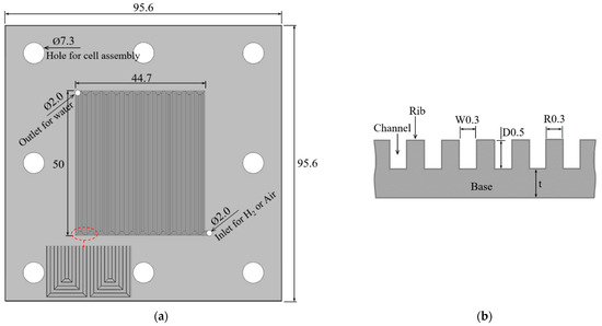
Figure 1.
Design of the BP for PBF 3D printing: (a) planal view; (b) cross-sectional view. Channel width of 0.3 mm (W0.3), channel depth of 0.5 mm (D0.5), and rib of 0.3 mm (R0.3) (unit: mm).
When the plate shape, like the BP, is printed with a metal 3D printer, bending may occur due to thermal deformation. Bending defects reduce the flatness of the BP, which makes the BP flow field partially contact the MEA. This phenomenon can damage the MEA, and the generated water cannot be discharged outside, thus deteriorating the fuel cell’s performance. The base thickness (t) of the BP was set as an output parameter to search for the thickness that would prevent bending. Therefore, three BPs were designed with a base thickness of 0.5 mm, 1.5 mm, and 2.5 mm, respectively. The thickness of the first BP was 1 mm (D = 0.5 + t = 0.5), the second BP was 2 mm (D = 0.5 + t = 1.5), and the third BP was 3 mm (D = 0.5 + t = 2.5).
3. Experiments
3.1. Manufacturing of Bipolar Plate with 300 μm Rectangle Channels by PBF 3D Printer
Metal 3D printers are broadly categorized into the PBF type and directed energy deposition (DED). PBF uses a powerful laser to precisely melt regions on the powder bed layer that are evenly spread using a recoating system. DED uses focused high-energy heat sources to fuse materials by melting as they are deposited. DED can differ from PBF as powders are often larger and require higher energy density. Furthermore, PBF offers higher precision compared with DED [26]. Therefore, a PBF device was used to fabricate the BP with a 0.3 mm channel. Figure 2 shows the schematic diagram of the process where the BP was built with a PBF 3D printer. The PBF 3D printer machine contained a 500 W fiber laser (DMP Flex 350 3D SYSTEMS, USA). The detailed processing parameters of the PBF 3D printer are shown in Table 1. Austenitic SUS 316L powder with an approximately sphere-like shape and an average diameter of 100 um was used. The chemical composition and thermophysical properties of SUS 316L are in Table 2 and Table 3, respectively. Three types of SUS 316L BPs with different base thicknesses were printed under the printing condition mentioned in Table 1.
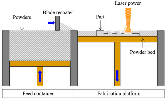
Figure 2.
Schematic of BP printing process in PBF.

Table 1.
Process parameters of PBF 3D printer.
Table 2.
Chemical composition of SUS 316L powder (wt.%).
Table 3.
Thermophysical properties of SUS 316L powder.
3.2. Analysis of Channel Cross-Section
A digital microscope examined and magnified planar-view images in the BP channel area. The channel was cut with a wire-cutting machine, magnified images of the channel cross-sections were examined using a digital microscope, and then the width and depth were measured. The channel’s 3D surface profile and surface roughness were measured using an optical surface roughness tester. The surface morphology of the rib cross-section was analyzed using scanning electron microscopy (SEM) to check the powder deposition profile and pore distribution.
3.3. Single-Cell Test
A single cell was prepared to conduct a fuel cell performance test of SUS 316L BPs manufactured by the PBF 3D printer and the fuel cell test system was prepared. Figure 3a shows the components of the single cell and the single cell with its components assembled. The single cell was composed of 2 aluminum end plates, 2 sets of gold-coated current collector plates, 2 sets of 3D printed SUS 316L BPs, 2 silicone gaskets, 2 sheets of carbon cloth, and 1 catalyst-coated membrane (CCM). The single-cell components were placed, and the cell was assembled under a pressure of 10 kgf/cm2 as shown in Figure 3b. Two cartridge heaters for heating and one thermocouple for measuring temperature were inserted into the end plate of the single cell. The specifications of the MEA used for the performance test are tabulated in Table 4. For the MEA, the CCM was combined with the gas diffusion layer (GDL). The GDL is carbon cloth with a microporous layer (MPL) made of polytetrafluoroethylene (PTFE). Platinum loading for the anode and cathode was 0.12 mg/cm2 and 0.45 mg/cm2, respectively. The active electrode area was 25 cm2.
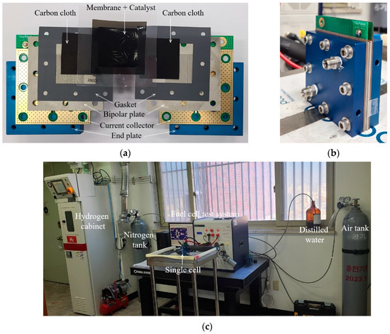
Figure 3.
Fuel cell equipment: (a) Single-cell components; (b) Assembled single cell; (c) Fuel cell system for performance test.
Table 4.
MEA specification for single-cell test.
The operating condition for the single-cell test and photos of the connection status of the testing equipment are presented in Table 5 and Figure 3c, respectively. Hydrogen was used in the anode and air in the cathode as reactant gases. After setting the humidification temperature at 75 °C, the humidified hydrogen was supplied at a flow rate of 300 ccm and humidified air at 750 ccm. The stoichiometry of hydrogen and air was 1.5 and 3, respectively. The temperature of the single cell was 75 °C, and the operating pressure was 1 atm. A 100 W electronic load (Smart2 PEM, WonATech) was used to measure the single cell’s performance (power, current density, etc.).
Table 5.
Operating condition for the single cell.
In this study, two types of BPs with a flow-field area of 2490 mm2 (50.0 mm × 49.8 mm) were prepared to compare the performance of an SUS 316L BP with 0.3 mm channels. Figure 4 shows two types of BPs for comparison. The graphite BP was prepared using a CNC machine with a channel width of 0.94 mm, channel depth of 1.0 mm, and rib of 0.94 mm. The SUS 316L BP was prepared using a metal 3D printer with a channel width of 0.94 mm, channel depth of 0.5 mm, and rib of 0.94 mm. As shown in Figure 4a, the graphite BP had the larger channel width and rib by more than 3 times and the larger channel depth by 2 times, respectively, compared to the BP in Figure 1. While the SUS 316L in Figure 4b had the larger channel width and rib width by more than 3 times that of the BP in Figure 1, the channel depth was the same. The area of the channels in both BPs was 1338.2 mm2 and more comprehensive by 206.4 mm2 (18.2%) than the BP (1131.8 mm2) in Figure 1. The configuration data of the BPs in Figure 4 are presented in Table 6.
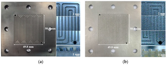
Figure 4.
Two BPs for comparison: (a) Graphite (W0.94, R0.94, and D1.0) by CNC machine; (b) SUS 316L (W0.94, R0.94, and D0.5) by metal 3D printer.
Table 6.
Configuration data of two bipolar plates for comparison.
For the continuous cycle operation of the single cell, the current was increased at 0.04 A/s, and the test was stopped when the voltage of the cell became 0.3 V, and then the setting was performed again to make the next cycle start. After 39 cycles of operations, the voltage and current values of the 40th cycle were adopted to draw the current–voltage (i-V) curve. The operation was repeated twice under the same condition to obtain reliable data while changing the MEA. The current density values were measured while operating the cell voltage at 0.6 V for 260 h to determine the long-term performance.
4. Experimental Results
4.1. Bipolar Plates with 300 μm Rectangle Channels Printed by PBF
4.1.1. Flatness
The BPs having the shape in Figure 1 were manufactured under the operating condition of the PBF as in Table 1. BPs with different thicknesses were designed and printed to investigate bending by thermal deformation. Figure 5 shows the samples’ photos fabricated while varying the thickness of the BP at 1 mm (t = 0.5 mm), 2 mm (t = 1.5 mm), and 3 mm (t = 2.5 mm). To observe bending, samples were placed on the flat floor toward the printing direction to take shots. In the case of the sample having a thickness of 1 mm, bending occurred and surfaces on both sides were lifted from the floor. The surfaces on both sides were lifted from the floor by about 2.1 mm, while the center surface was lifted about 1.0 mm from the floor. On the contrary, a sample with a thickness of 2 mm did not bend, and the sample surfaces were almost in contact with the floor. The sample with a thickness of 3 mm had to bend even if it was thicker by 1 mm than the sample with a thickness of 2 mm. The surfaces on both sides were lifted about 0.8 mm, and the central surface, about 0.4 mm, was lifted from the floor.
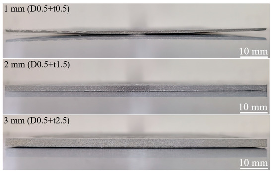
Figure 5.
Bending confirmation of three types of PBF-built SUS 316L BPs.
4.1.2. Appearance
The time taken to print the BP with a thickness of 1 mm was 1 h 25 min; 2 mm, 3 h 10 min; and 3 mm, 4 h 55 min. Figure 6 shows the SUS 316L BPs manufactured through PBF. It was confirmed that there was no defect on the surface, and the print was completed perfectly until the flow field with 0.3 mm channels. Since the reproducibility of 3D printers is remarkably high, the samples with the same quality can be repeatedly printed if printing is executed under the same condition. The first produced BP, the second BP, and the third BP were all printed perfectly.
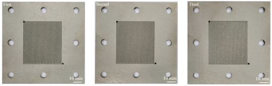
Figure 6.
Planar view of PBF-built SUS 316L BPs with a thickness of 2 mm.
A digital microscope magnified the channel part to examine the printing condition more closely. The images taken from the seven regions of the flow field are presented in Figure 7a. The region with a number indicates the position of shooting. From the magnified planar view, there were no blockages in the channels. The ribs were also deposited almost straight. There was a concern that the ribs might not be deposited as straight in the region where the channel was bent at 90°. However, the ribs were built similarly to the designed shape in the bent area.
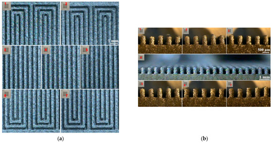
Figure 7.
Digital microscope image of the flow field of the PBF-built SUS 316L BP: (a) Planar view; (b) Cross-sectional view.
Nonetheless, circular projections existed on the surface of some places, thus showing a rough surface. After cutting the channel, the cross-section shapes magnified by the digital microscope were measured, and the images are presented in Figure 7b. There was no blockage in all the seven regions. Although the top and side of the ribs were rough, the shape was rectangular, similarly as the design shape. However, some pores were found in the ribs.
The surface morphologies were measured for a cross-section of the ribs after mounting and polishing using SEM to observe the deposit shape of the ribs. The cross-sectional images of the ribs measured using SEM are presented in Figure 8. The shape of the ribs was rectangular with ragged edges. Micropores were found in various locations in the ribs. However, no porosity was observed from the base region below the ribs. The PBF 3D printer builds the BP from the base and then the ribs. The particle size of the powder was less than 100 μm, and its size varied when the rib of 300 μm was built and 3–10 particles were used in one layer. If large-sized particles were used, the gap was not narrowed down and remained as pores since the gap between particles was significant even after melting. Therefore, it might have been attributed to the irregular side surface of the ribs and was porous. Such a phenomenon can be resolved if the particle size is more minute in the powder and the sizes of the particles become uniform.
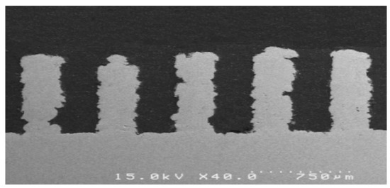
Figure 8.
SEM image of the flow field of the PBF-built SUS 316L BP.
4.1.3. Width and Depth of Channels
The channel width and depth of images taken by the digital microscope from the seven regions were measured using the image analysis function as in Figure 7b. The channel width and depth data for seven regions in the flow field are presented as graphs in Figure 9. The width and depth of the channel did not differ much depending on the region. The channel’s width was about 0.29 mm smaller by about 0.01 mm than the design width (0.3 mm). Because the side faces of the ribs were rough, the channel’s maximum and minimum width differed by about 0.14 mm, which was why the error bar in the graph was expressed as significant. The depth of the channels (rib height) was 0.57–0.58 mm, which was higher by about 0.07 mm than the design width (0.5 mm). The difference between the maximum and the minimum channel depth was about 0.05 mm, which was smaller than the channel width by about 3 times. The channel width became narrower by 0.01 mm than the design width because powder spread to the side due to its weight during melting. The channel depth was higher by 0.07 mm than the design because the top of the deposited rib was not flat but was projected round.
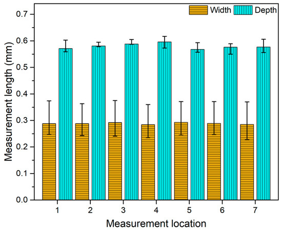
Figure 9.
Dimension of channel width and depth of PBF-built SUS 316L BP.
4.1.4. Surface Roughness
The 3D surface profile and surface roughness were measured at the channel of the SUS 316L BP produced through PBF using an optical surface roughness tester. As comparison data, the graphite BP produced by the CNC machine in Figure 4a was also measured. The 3D surface profile of the channel measured by the optical surface roughness tester is presented in Figure 10. The X-axis of the 3D surface profile was in the channel width direction, and the Y-axis was in the channel length direction. As confirmed from the 3D surface profile, the SUS 316L BP had higher surface peaks, more profound valleys than the graphite BP produced by the CNC machine, and more minute projections. The surface roughness values of the 3D surface profile were measured from the exact center to the X-axis and Y-axis, respectively. The arithmetic average roughness (Ra) values of the X-axis and Y-axis of the SUS 316L BP were 4.663 μm and 4.316 μm, respectively. While the Ra value of the X-axis and Y-axis of the graphite BP were 1.565 μm and 2.519 μm, respectively, the Ra value of the Y-axis was higher than that of the X-axis by 1.6 times. The channel of the graphite BP was machined toward the channel length (Y-axis) using an end mill with the same diameter as the channel width. The end mill impression was formed toward the channel length in the bottom. Therefore, the Ra value of the Y-axis was higher than that of the X-axis by 1.6 times. In the case of the SUS 316L BP, since the particle size of the powder was smaller than 100 μm and sizes were varied, at least more than three powders were melted at the channel bottom. Therefore, the roughness was similar regardless of the X-axis and Y-axis. The surface layer formed due to the melting of the powder and was rougher by 3 times in the channel width direction and by more than 1.7 times in the channel length direction than that in the surface produced by cutting with the end mill. Wang et al. [33] reported that a GDL with higher roughness showed the greater contact angle with water, which will facilitate water discharge in the GDL, which will improve the performance of the PEMFC. Similar to this study, it is expected to favor the performance of the PEMFC such as water transport behavior and PEMFC power density due to the high roughness of the BP applied by the 3D-printing method.
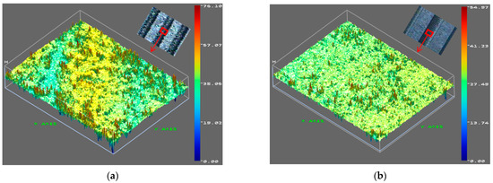
Figure 10.
Three-dimensional surface profile at channel: (a) PBF-built SUS 316L BP(W0.29, R0.31, and D0.57); (b) CNC-machined graphite BP (W0.94, R0.94, and D1.0).
4.2. Cell Performance
4.2.1. i-V Curve (Short-Term Performance)
The performance test was carried out by combining the BPs of 2 mm with the single cell, and was also performed by combining a single cell and 1 mm- and 3mm-thick BPs with occurring bending. In both the conditions, the reactant gases did not leak out, and there was no deterioration in performance caused by the MEA damage, nor did the blockage of water create discharge.
Figure 11 shows the i-V curve in the 40th cycle of three types of BPs (Figure 4 and Figure 6). The polarization curve of a PEM fuel cell can be divided into three major sections due to activation loss, ohmic loss, and concentration loss. As can be seen in Figure 11, at a low current densities range (i.e., i < 0.02 A/cm2), where the activation loss has a strong effect on the initial rapid drop in the i-V polarization curves, the i-V polarization curves for fuel cells with all BPs have different behaviors despite same operation conditions such as the flow rate of fuel and air, cell temperature, pressure, and identical MEA use. The different amount of activation loss may be due to the difference in diffusion concentration in the fuel (hydrogen and oxygen) (i.e., reactant concentration effects) according to the different patterns of the BPs. In the case of BPs made of the same SUS 316L material, the BP with 0.3 mm channel width and 0.3 mm ribs (W0.3, R0.3, and D0.5) showed the better i-V polarization performance because of better convection and diffusion of fuels (hydrogen and oxygen gases). In addition, a difference in i-v performance due to the activation loss according to the BPs of SUS 316L and graphite having the same width of channel and rib was clearly found, but its reasons according to the material difference of the BPs are not clear. The linear slope shown in the i-V polarization curves is contributed by the ohmic loss due to the charge transport of ions and electrons. The difference between the BPs of SUS 316L and graphite drives the difference in the transport of electrons from the anode to the cathode due to different electrical conductivity, while that between the same SUS 316L BPs is contributed by the concentration gradient originating from the different size of channels and ribs. Concentration losses happened in the tail section of the i-V curve because of mass transport. The concentration loss was strongly affected by mass transport in the fuel cell electrodes and fuel cell flow structures. The different fuel cell flow structure due to different BPs’ channel shape led to different convection of the reactant and product. Both SUS 316L (W0.94, R0.94, and D0.5) and graphite (W0.94, R0.94, and D1.0) BPs with a similar channel structure showed steep decline in the same current density range. The current density of the SUS 316L BP (W0.29, R0.31, and D0.57) at 0.6 V was 1.2052 A/cm2. The current density of the SUS 316L BP (W0.94, R0.94, and D0.5) and graphite BP (W0.94, R0.94, and D1.0) at 0.6 V were 0.7888 and 0.9652 A/cm2, respectively.
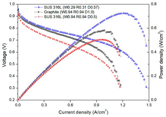
Figure 11.
i-V curve in the 40th cycle of three types of BPs: SUS 316L (W0.29, R0.31, and D0.57), graphite (W0.94, R0.94, and D1.0), and SUS 316L (W0.94, R0.94, and D0.5).
The zone where the rib and MEA contacted was the dead zone where reaction did not occur. As the rib width decreased, the area where the rib and MEA contacted became reduced. The narrower the channel width, the higher the number of the channel was. Conversely, the larger the rib width of the BP, the larger the dead zone, while as the channel width increased, the channel quantity became smaller. Figure 12 shows the image expressing the area where the channels contacted the MEA for the BP with 0.3 mm channel width and 0.3 mm ribs and the BP with 0.94 mm channel width and 0.94 mm ribs. In the case of the BP with channels and ribs of 0.3 mm, all the active areas took place in a uniform reaction where hydrogen movement occurred. For the BP with channels and ribs of 0.94 mm, an uneven reaction may have occurred in which hydrogen movement was concentrated in a specific zone or did not occur in other zones. Therefore, the difference may have occurred between two BPs.
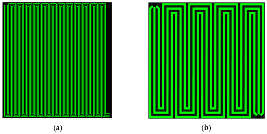
Figure 12.
Area where the channels contacted the MEA: (a) BP with W0.3, R0.3; (b) BP with W0.94, R0.94.
4.2.2. Time–Current Density Curve (Long-Term Performance)
The current density of the SUS 316L BP (W0.29 R0.31 D0.57) produced through PBF was measured under 0.6 V for 260 h. The measuring equipment was not allowed to be off for even a moment during the 260 h. Figure 13 is the graph depicting the current density of 0.6 V for 260 h. The performance was gradually increased when the operation started, followed by an abrupt drop, and then maintained till 260 h. The current density at the 40th cycle (10 h) was 1.2052 A/cm2 during the cycle operation in Figure 11. In the operation with a fixed voltage at 0.6 V, the current density at 10 h elapsed was 1.1676 A/cm2. The current density was at a maximum of 1.1732 A/cm2 at 13 h, then reduced to 0.000561 A/cm2 per hour. The current density was 1.0852 A/cm2 at 170 h, decreasing from 171 h by about 0.0464 A/cm2 before reaching 1.0388 A/cm2. The current density was not decreased from 171 h to 260 h and remained between 1.0616 and 1.0296 A/cm2.
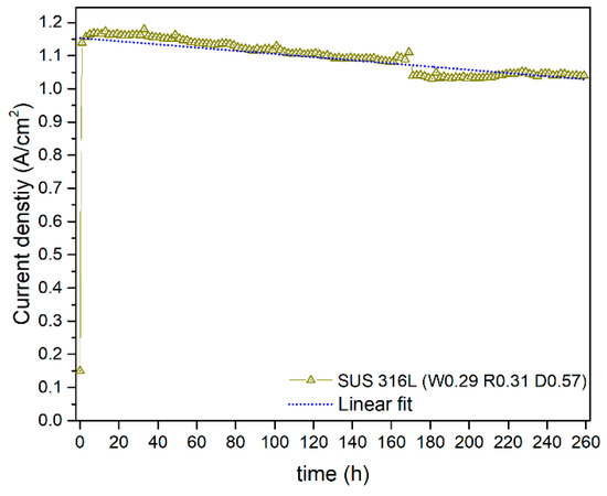
Figure 13.
Current density at 0.6 V for 260 h operation of the single cells with PBF-built SUS 316L BP (W0.29, R0.31, and D0.57).
5. Conclusions
This study manufactured an SUS 316L BP with 300 μm channels in a serpentine flow field using a PBF 3D printer. A single-cell performance test was conducted for the fabricated SUS 316L BPs, and some beneficial results could be drawn.
- (1)
- The BP sample with a thickness of 1 mm had a bending phenomenon due to thermal deformation, while the sample with a thickness of 2 mm was not bent. The BP had a thickness of 1 mm. Although it had a low flatness due to bending, it was flexible enough to undergo elastic deformation to be flat by a compressive force when combined with a single cell. Therefore, all the regions in the flow field of the BP with a thickness of 1 mm adhered to the MEA excellently, so the reactant gases were not leaked out.
- (2)
- The fabricated SUS 316L BP channel shape was rectangular as in the design. The channel width was about 0.29 mm smaller by about 0.01 mm than the design size (0.3 mm), while the channel depth was 0.57 mm deeper by about 0.07 mm than the design depth (0.5 mm). The average arithmetic roughness (Ra) value was 4.316 μm, which was higher by 1.7 times than that of the CNC machined graphite BP. Porosities were almost not found from the base of the ribs, but pores were observed from various regions of the ribs, and its edges were ragged due to pores.
- (3)
- The current density of the manufactured SUS 316L BP with 0.29 mm channels (rectangle, 0.6 mm channel depth, and 0.3 mm ribs) was 1.2052 A/cm2 at 0.6 V. This value was higher by 24.9% than that of the graphite BP with 0.94 mm channels (rectangle, 1.0 mm channel depth, and 0.94 mm ribs). In addition, the current density was higher by 52.8% than that of the SUS 316L BP with 0.94 mm channels (rectangle, 0.5 mm channel depth, and 0.94 mm ribs).
- (4)
- The current density of the prepared SUS 316L BP with 0.29 mm channels reached a maximum at 1.1732 A/cm2 at 13 h in the long-term operation and reduced by 0.000561 A/cm2 per hour till 170 h. From 171 h to 260 h, the current density value was maintained at 1.0616 to 1.0296 A/cm2.
The BP proposed in this study was designed to have a flow field at only one side for the performance test of the single cell. However, with a PBF 3D printer, a BP with flow fields at both sides and a coolant channel at the center of the cross-section can be made. BPs manufactured by a 3D printer must be analyzed in various directions. Future studies will consider the following: the effect of the rough surface of the rib on the interface contact resistance between the GDL and BP; the effect of the rough surface on the reactant and coolant delta P; the local current redistribution that results from changes in plate thickness; and quantifying the porosity of the BP web.
Author Contributions
Conceptualization, C.K.J. and J.H.K.; methodology, C.K.J.; software, J.H.K.; validation, C.K.J. and J.H.K.; formal analysis, C.K.J.; investigation, C.K.J. and J.H.K.; resources, C.K.J. and J.H.K.; data curation, C.K.J. and J.H.K.; writing—original draft preparation, C.K.J. and B.-S.L.; writing—review and editing, C.K.J.; visualization, C.K.J.; supervision, B.-S.L.; project administration, B.-S.L.; funding acquisition, C.K.J. All authors have read and agreed to the published version of the manuscript.
Funding
These results were supported by “Regional Innovation Strategy (RIS)” through the National Research Foundation of Korea (NRF) funded by the Ministry of Education(MOE)(2021RIS-003). This work was supported by the National Research Foundation of Korea (NRF) grant funded by the Korea Government (MSIT) (No. NRF-2020R1F1A1067912).
Data Availability Statement
All datasets associated with this research are available upon request to the corresponding author.
Conflicts of Interest
The authors declare no conflict of interest.
References
- Xing, L.; Shi, W.; Su, H.; Xu, Q.; Das, P.K.; Mao, B.; Scott, K. Membrane electrode assemblies for PEM fuel cells: A review of functional graded design and optimization. Energy 2019, 177, 445–464. [Google Scholar] [CrossRef]
- Pahon, E.; Bouquain, D.; Hissel, D.; Rouet, A.; Vacquier, C. Performance analysis of proton exchange membrane fuel cell in automotive applications. J. Power Sources 2021, 510, 230385. [Google Scholar] [CrossRef]
- Wu, S.; Yang, W.; Yan, H.; Zuo, X.; Cao, Z.; Li, H.; Shi, M.; Chen, H. A review of modified metal bipolar plates for proton exchange membrane fuel cells. Int. J. Hydrog. Energy 2021, 46, 8672–8701. [Google Scholar] [CrossRef]
- Xiong, K.; Wu, W.; Wang, S.; Zhang, L. Modeling, design, materials and fabrication of bipolar plates for proton exchange membrane fuel cell: A review. Appl. Energy 2021, 301, 117443. [Google Scholar] [CrossRef]
- Chen, K.; Laghrouche, S.; Djerdir, A. Performance analysis of PEM fuel cell in mobile application under real traffic and environmental conditions. Energy Convers. Manag. 2021, 227, 113602. [Google Scholar] [CrossRef]
- Song, Y.; Zhang, C.; Ling, C.Y.; Hand, M.; Yong, R.Y.; Sun, D.; Chen, J. Review on current research of materials, fabrication and application for bipolar plate in proton exchange membrane fuel cell. Int. J. Hydrog. Energy 2020, 45, 29832–29847. [Google Scholar] [CrossRef]
- Duan, Z.; Qu, Z.; Ren, Q.; Zhang, J. Review of Bipolar Plate in Redox Flow Batteries: Materials, Structures, and Manufacturing. Electrochem. Energy Rev. 2021, 4, 718–756. [Google Scholar] [CrossRef]
- Leng, Y.; Ming, P.; Yang, D.; Zhang, C. Stainless steel bipolar plates for proton exchange membrane fuel cells: Materials, flow channel design and forming processes. J. Power Sources 2020, 451, 227783. [Google Scholar] [CrossRef]
- Xu, Z.; Qiu, D.; Yi, P.; Peng, L.; Lai, X. Towards mass applications: A review on the challenges and developments in metallic bipolar plates for PEMFC. Prog. Nat. Sci. 2020, 30, 815–824. [Google Scholar] [CrossRef]
- Porstmann, S.; Wannemacher, T.; Drossel, W.G. A comprehensive comparison of state-of-the-art manufacturing methods for fuel cell bipolar plates including anticipated future industry trends. J. Manuf. Process. 2020, 60, 366–383. [Google Scholar] [CrossRef]
- Mahabunphachai, S.; Cora, O.N.; Koc, M. Effect of manufacturing processes on formability and surface topography of proton exchange membrane fuel cell metallic bipolar plates. J. Power Sources 2010, 195, 5269–5277. [Google Scholar] [CrossRef]
- Liu, Y.; Hua, L. Fabrication of metallic bipolar plate for proton exchange membrane fuel cells by rubber pad forming. J. Power Sources 2010, 195, 3529–3535. [Google Scholar] [CrossRef]
- Hung, J.C.; Lin, C.C. Fabrication of micro-flow channels for metallic bipolar plates by a high-pressure hydroforming apparatus. J. Power Sources 2012, 206, 179–184. [Google Scholar] [CrossRef]
- Hung, J.C.; Yang, T.C.; Li, K.C. Studies on the fabrication of metallic bipolar plates-Using micro electrical discharge machining milling. J. Power Sources 2011, 196, 2070–2074. [Google Scholar] [CrossRef]
- Abeyrathna, B.; Zhang, P.; Pereira, M.P.; Wilkosz, D.; Weiss, M. Micro-roll forming of stainless steel bipolar plates for fuel cells. Int. J. Hydrog. Energy 2019, 44, 3861–3875. [Google Scholar] [CrossRef]
- Jin, C.K.; Kang, C.G. Fabrication process analysis and experimental verification for aluminum bipolar plates in fuel cells by vacuum die-casting. J. Power Sources 2011, 196, 8241–8249. [Google Scholar] [CrossRef]
- Jin, C.K.; Jung, M.G.; Kang, C.G. Fabrication of Aluminum Bipolar Plates by Semi-solid Forging Process and Performance Test of TiN Coated Aluminum Bipolar Plates. Fuel Cells 2014, 21, 551–560. [Google Scholar] [CrossRef]
- Development of Bi-Polar Plates for Fuel Cells JAPAN. Available online: https://www.syvec.co.jp/en/rd/plates/ (accessed on 19 October 2022).
- Li, X.; Sabir, I. Review of bipolar plates in PEM fuel cells: Flow-field designs. Int. J. Hydrog. Energy 2005, 30, 359–371. [Google Scholar] [CrossRef]
- Peng, L.; Yi, P.; Lai, X. Design and manufacturing of stainless steel bipolar plates for proton exchange membrane fuel cells. Int. J. Hydrog. Energy 2014, 39, 21127–21153. [Google Scholar] [CrossRef]
- Wang, Y.; Zhou, B.; Liu, Z.; Tu, Z.; Liu, W. Numerical study and performance analyses of the mini-channel with discrete double-inclined ribs. Int. J. Heat Mass Transf. 2014, 78, 498–505. [Google Scholar] [CrossRef]
- Askari, M.; Hutchins, D.A.; Thomas, P.J.; Astolfi, L.; Watson, R.L.; Abdi, M.; Ricci, M.; Laureti, S.; Nie, L.; Freear, S.; et al. Additive manufacturing of metamaterials: A review. Addit. Manuf. 2020, 36, 101562. [Google Scholar] [CrossRef]
- Slotwinski, J.A.; Garboczi, E.J.; Stutzman, P.E.; Ferraris, C.F.; Watson, S.S.; Peltz, M.A. Characterization of Metal Powders Used for Additive Manufacturing. J. Res. Natl. Inst. 2014, 119, 460–493. [Google Scholar] [CrossRef] [PubMed]
- Housholder, R.F. Molding Process. U.S. Patent 4247508, 27 January 1981. [Google Scholar]
- Savolainen, J.; Collan, M. How Additive Manufacturing Technology Changes Business Models—Review of Literature. Addit. Manuf. 2020, 32, 01070. [Google Scholar] [CrossRef]
- Yusuf, S.M.; Cutler, S.; Gao, N. Review: The Impact of Metal Additive Manufacturing on the Aerospace Industry. Metals 2019, 9, 1286. [Google Scholar] [CrossRef]
- Zhang, L.; Zhang, S.; Zhu, H.; Hu, Z.; Wang, G.; Zeng, X. Horizontal dimensional accuracy prediction of selective laser melting. Mater. Des. 2018, 160, 9–20. [Google Scholar] [CrossRef]
- Izonin, I.; Tkachenko, R.; Gregus, M.; Duriagina, Z.; Shakhovska, N. PNN-SVM Approach of Ti-Based Powder’s Properties Evaluation for Biomedical Implants Production. Comput. Mater. Contin. 2022, 71, 5933–5947. [Google Scholar] [CrossRef]
- Izonin, I.; Tkachenko, R.; Duriagina, Z.; Shakhovska, N.; Kovtun, V.; Lotoshynska, N. SmartWeb Service of Ti-Based Alloy’s Quality Evaluation for Medical Implants Manufacturing. Appl. Sci. 2022, 12, 5238. [Google Scholar] [CrossRef]
- Gould, B.D.; Rodgers, J.A.; Schuette, M.; Bethune, K.; Louis, S.; Rocheleau, R.; Lyons, K.S. Performance and Limitations of 3D-Printed Bipolar Plates in Fuel Cells. ECS J. Solid State Sci. Technol. 2015, 4, 3063–3068. [Google Scholar] [CrossRef]
- Trogadas, P.; Cho, J.I.S.; Neville, T.P.; Marquis, J.; Wu, B.; Brett, D.J.L.; Coppens, M.O. A lung-inspired approach to scalable and robust fuel cell design. Energy Environ. Sci. 2018, 11, 136–143. [Google Scholar] [CrossRef]
- Zhang, C.; Wang, S.; Li, J.; Zhu, Y.; Peng, T.; Yang, H. Additive manufacturing of products with functional fluid channels: A review. Addit. Manuf. 2020, 36, 101490. [Google Scholar] [CrossRef]
- Wang, X.L.; Qu, Z.G.; Lai, T.; Ren, G.F.; Wang, W.K. Enhancing water transport performance of gas diffusion layers through coupling manipulation of pore structure and hydrophobicity. J. Power Sources 2022, 525, 231121. [Google Scholar] [CrossRef]


Publisher’s Note: MDPI stays neutral with regard to jurisdictional claims in published maps and institutional affiliations. |
© 2022 by the authors. Licensee MDPI, Basel, Switzerland. This article is an open access article distributed under the terms and conditions of the Creative Commons Attribution (CC BY) license (https://creativecommons.org/licenses/by/4.0/).