
A State-Observer-Based Protection Scheme for AC Microgrids with Recurrent Neural Network Assistance
 , , , and
Abstract
:1. Introduction
1.1. Problem Statement and Prime Objective
1.2. Literature Review
1.3. Limitations in Existing Schemes
1.4. Significant Contributions
- Novel deployment of particle filters in microgrid protection schemes as a state observer with RNN support;
- First-time utilization of particle filters in the time and frequency domain for harmonics extraction;
- The scheme threshold value does not depend on the type of fault and microgrid system configuration;
- PF catering to the measurement noise autonomously is another feature of the proposed scheme [25];
- LI, as well as HI faults, are detected in the proposed scheme in both modes and different microgrid topologies;
- The proposed scheme provides backup protection in case of primary relay failure.
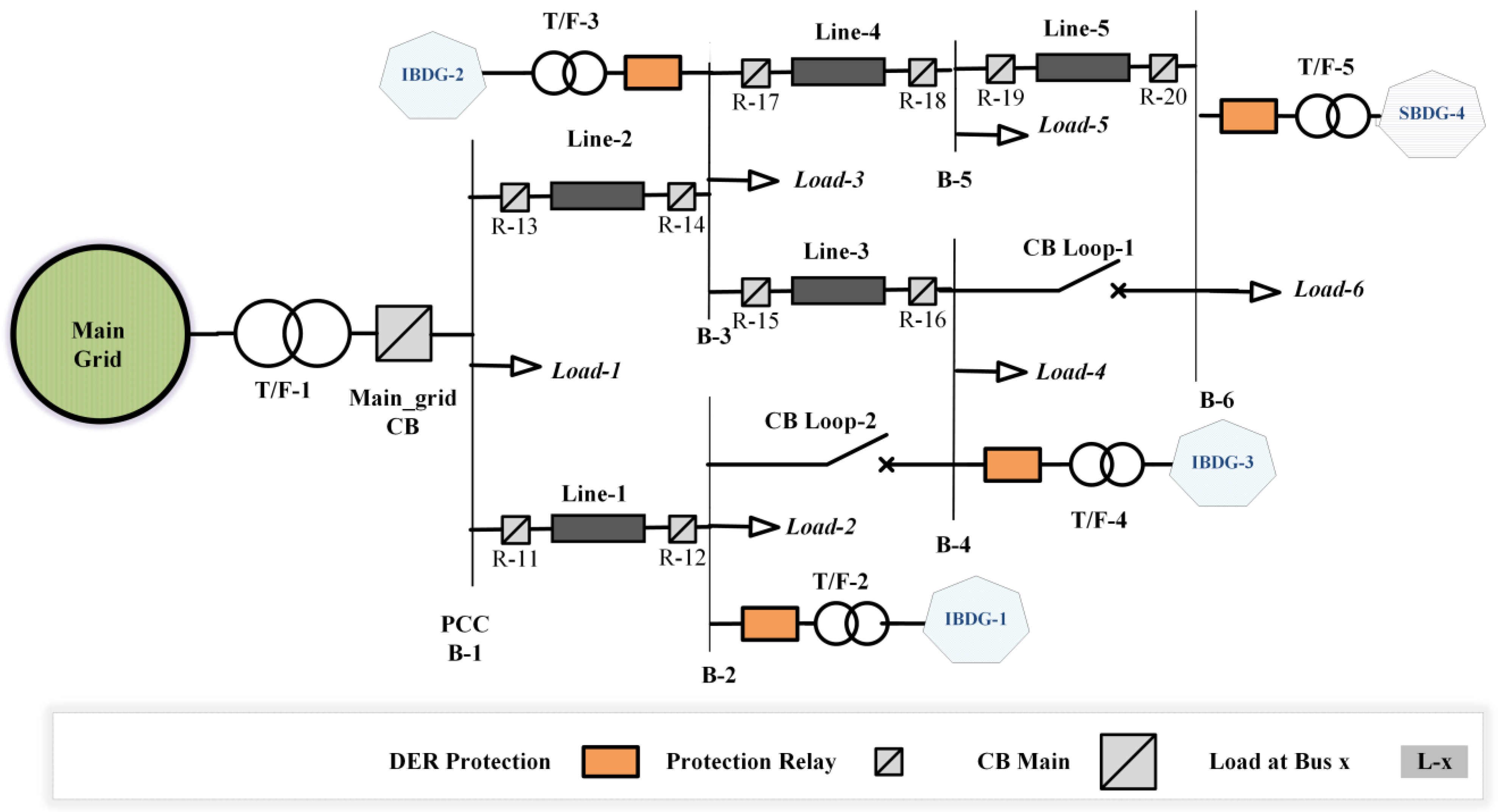
2. IEC Microgrid TEST Bed
3. Mathematical Modeling
3.1. Per-Phase Microgrid Signals Formulation
3.2. State-Space Model
3.3. Particle Filter as a State Observer
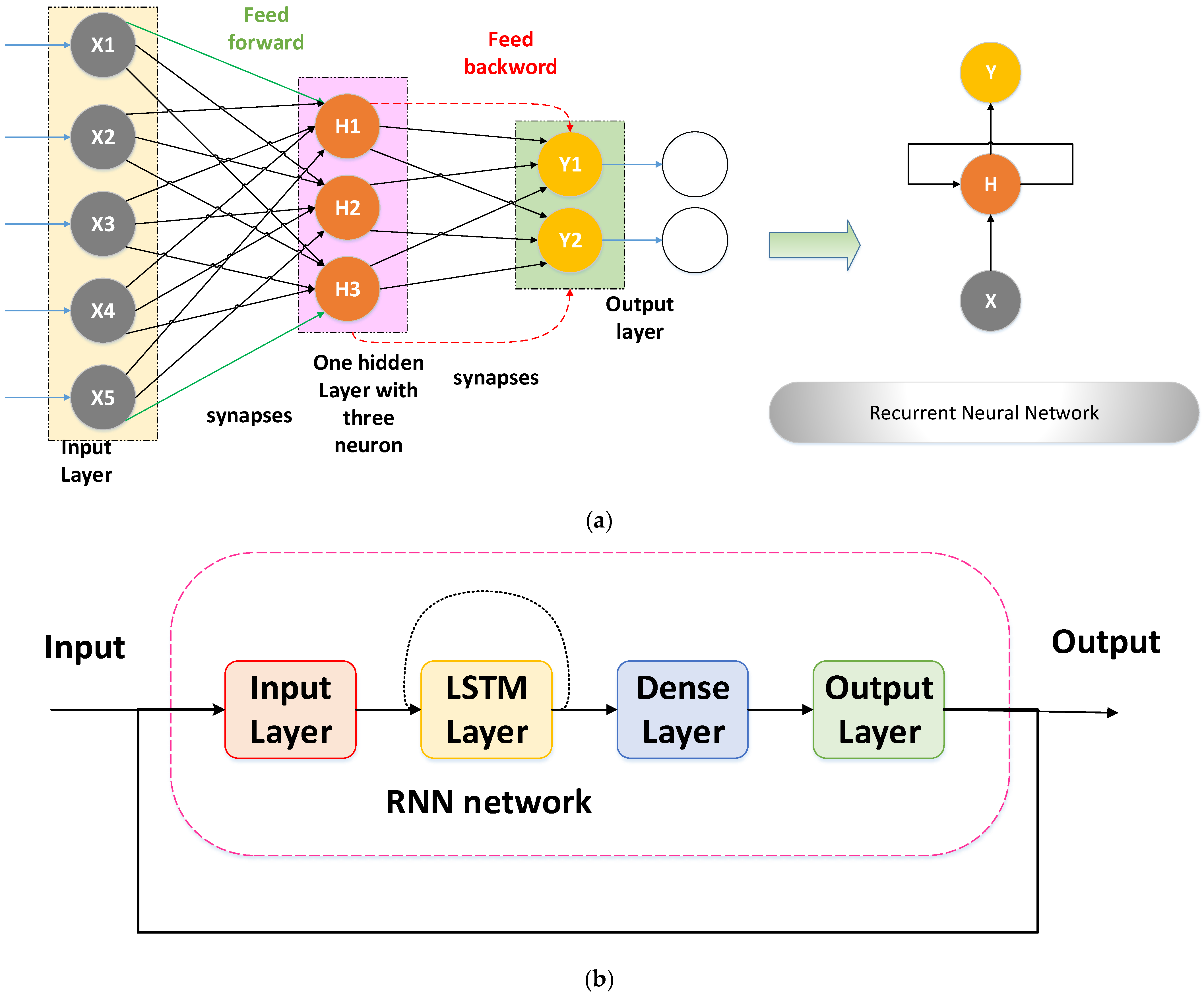
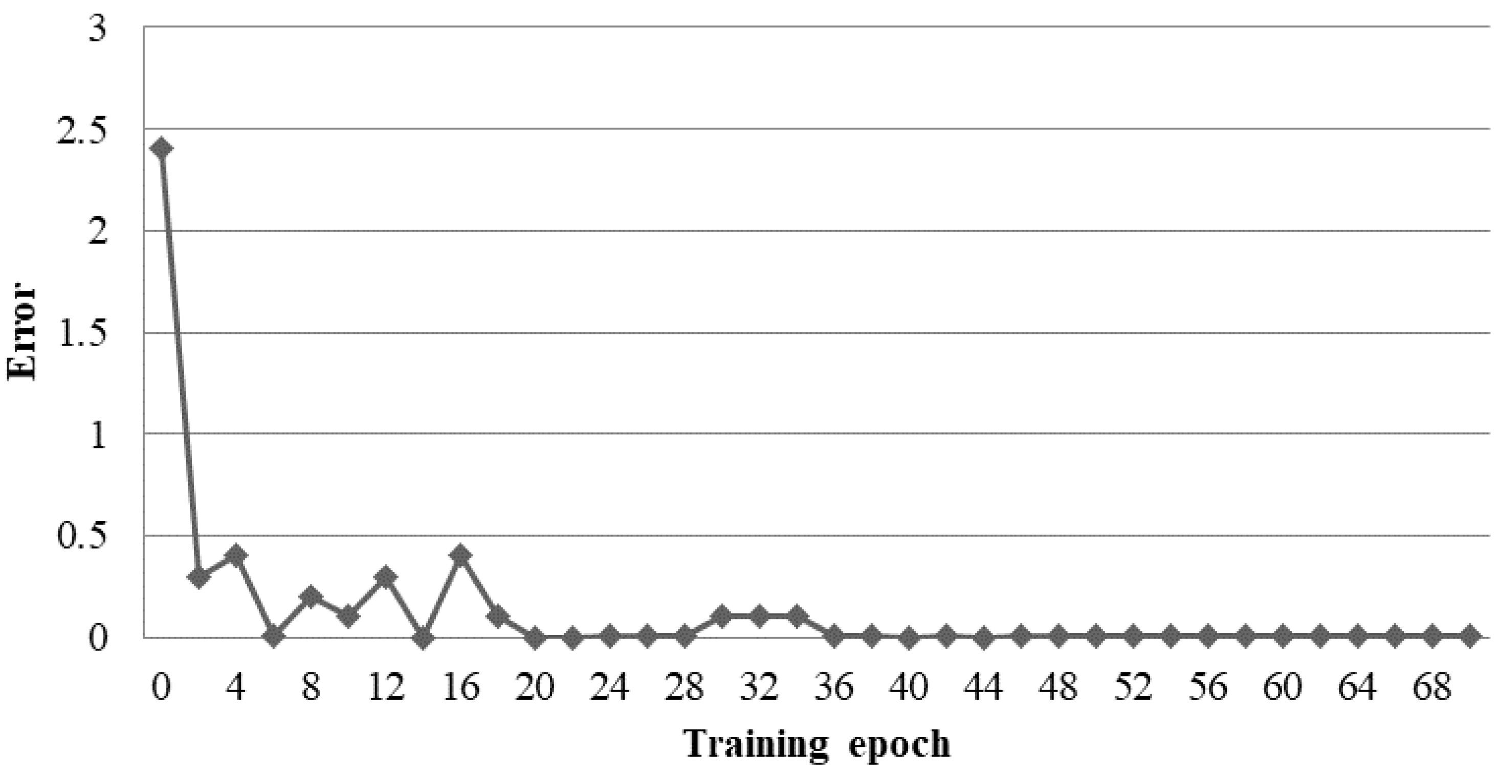
3.4. Recurrent Neural Networks
3.5. PFD and SOE Calculations
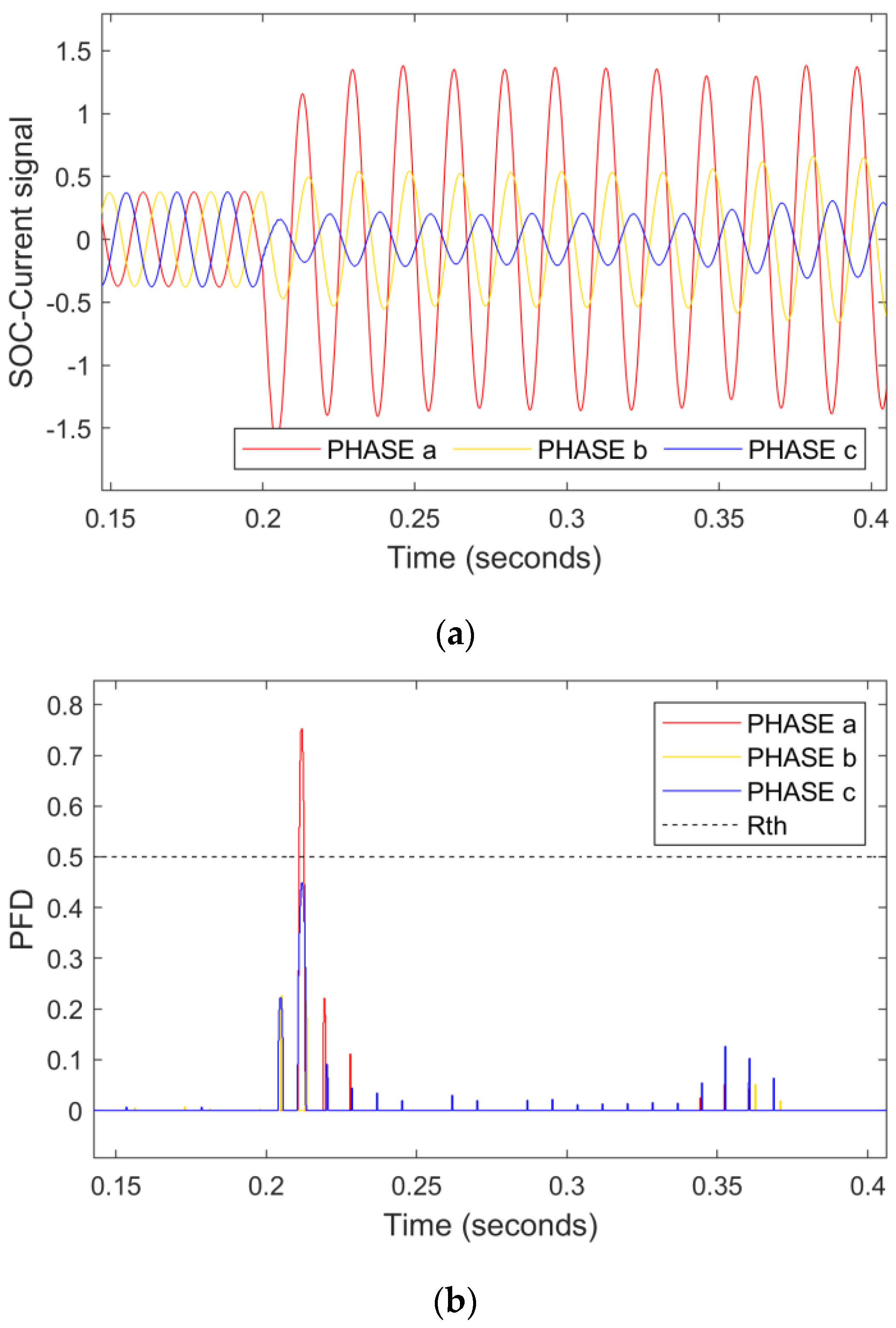
3.5.1. PFD
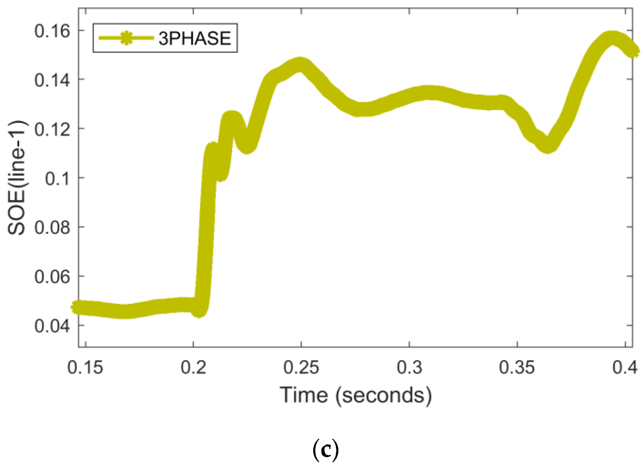
3.5.2. SOE
3.6. SOE Directional Analysis
3.7. Predefined Threshold
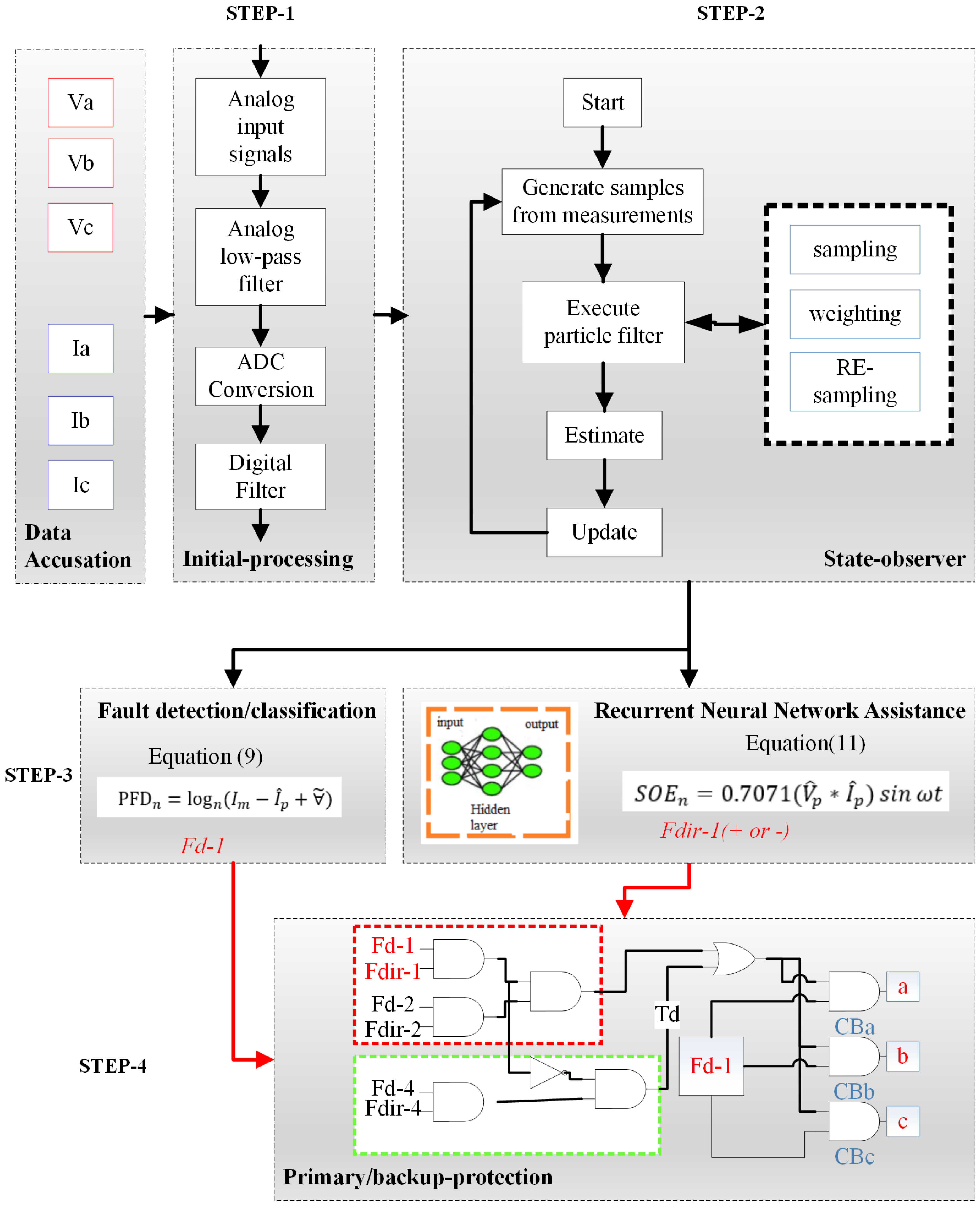
4. Proposed SO-Based Relay
4.1. Step 1
4.2. Step 2
4.3. Step 3
4.4. Step 4
5. Communication-Assisted Decision Unit
6. Results
6.1. Backup Protection Case Study
6.2. TU-Mode Case Study
6.2.1. LI-Fault at Line-2
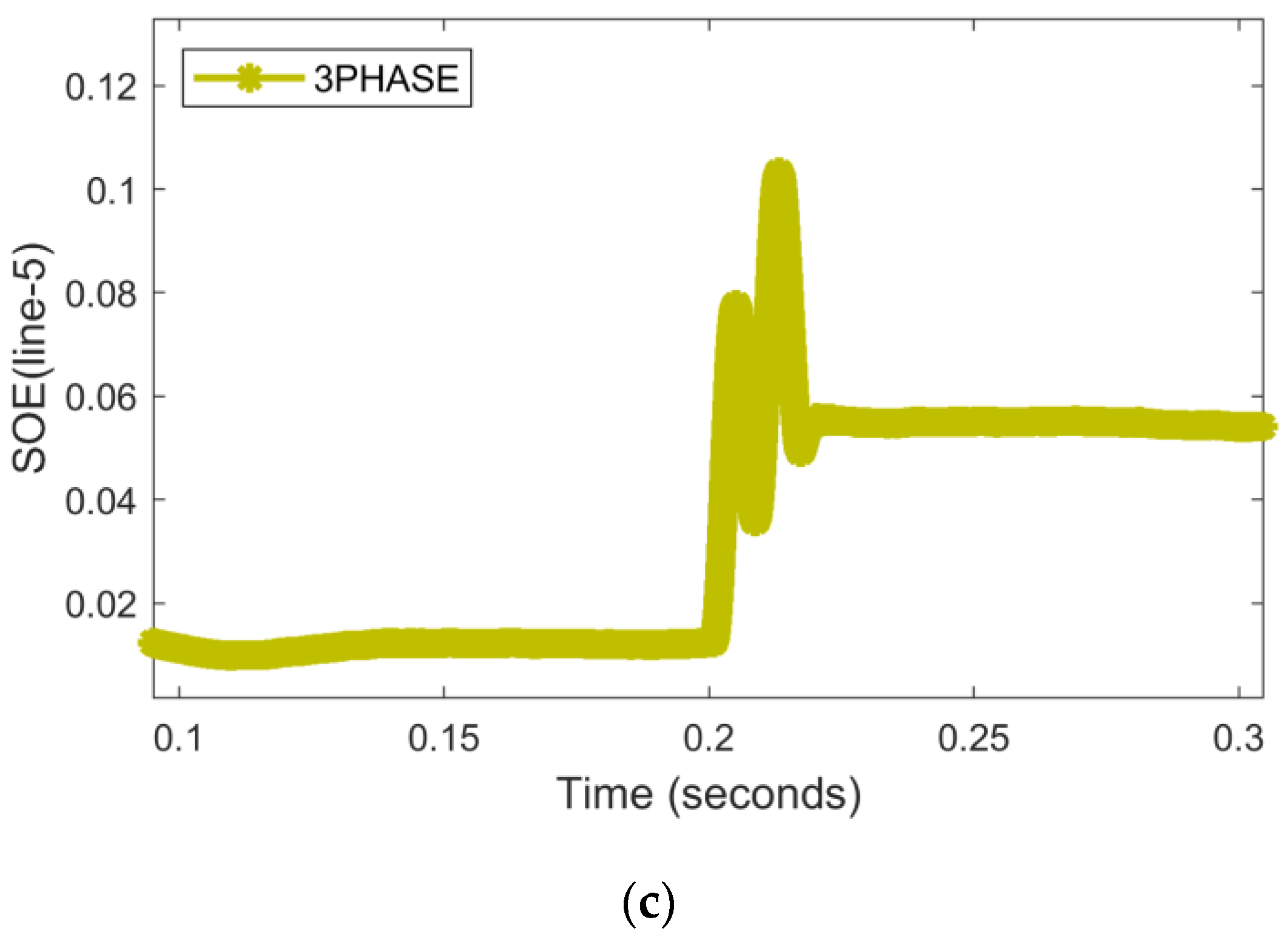
6.2.2. HI-Fault at Line-4
6.3. IN-Mode Case Study
6.3.1. LI-Fault at Line-1
6.3.2. HI-Fault at Line-3
6.4. Single-Phase Tripping
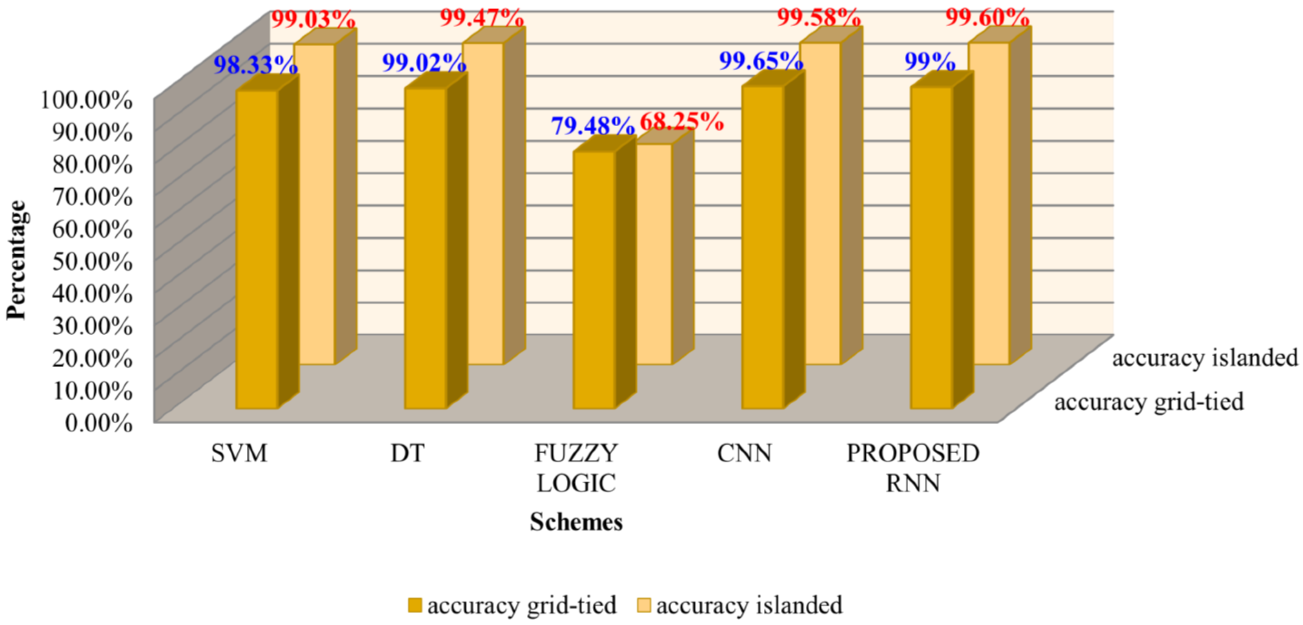
7. Performance Comparison with Previous Schemes
8. Conclusions
Author Contributions
Funding
Data Availability Statement
Conflicts of Interest
Appendix A
| Particle filter algorithm steps |
| Input: {xi k−1, wi k−1} Ns i = 1, zk Output: {xi k, wi k} Ns i = 1 wsum = 0 for i = 1, …, Ns do Step 1: propagate particle draw sample xi k ∼ q(xi k|xi k−1, zk) Step 2: update weight assign weight wi k Step 3: cumulative weight wsum = wsum + wi k End normalize weights for i = 1, …, Ns do wi k = wi k/wsum End Resample Ns particles with replacement for i = 1, …, Ns do wi k = 1/Ns End |
References
- Chandra, A.; Singh, G.K.; Pant, V. Protection Techniques for DC Microgrid—A Review. Electr. Power Syst. Res. 2020, 187, 106439. [Google Scholar] [CrossRef]
- Vegunta, S.C.; Higginson, M.J.; Kenarangui, Y.E.; Li, G.T.; Zabel, D.W.; Tasdighi, M.; Shadman, A. AC Microgrid Protection System Design Challenges—A Practical Experience. Energies 2021, 14, 2016. [Google Scholar] [CrossRef]
- Liu, D.; Dysko, A.; Hong, Q.; Tzelepis, D.; Booth, C.D. Transient Wavelet Energy-Based Protection Scheme for Inverter-Dominated Microgrid. IEEE Trans. Smart Grid 2022, 13, 2533–2546. [Google Scholar] [CrossRef]
- Dehghanpour, E.; Normandeau, M.; Joos, G.; Brissette, Y. A Protection System for Inverter Interfaced Microgrids. IEEE Trans. Power Deliv. 2022, 37, 2314–2325. [Google Scholar] [CrossRef]
- Abeid, S.; Hu, Y.; Alasali, F.; El-Naily, N. Innovative Optimal Nonstandard Tripping Protection Scheme for Radial and Meshed Microgrid Systems. Energies 2022, 15, 4980. [Google Scholar] [CrossRef]
- Patnaik, B.; Mishra, M.; Bansal, R.C.; Jena, R.K. AC Microgrid Protection—A Review: Current and Future Prospective. Appl. Energy 2020, 271, 115210. [Google Scholar] [CrossRef]
- Altaf, M.W.; Arif, M.T.; Islam, S.N.; Haque, M.E. Microgrid Protection Challenges and Mitigation Approaches-A Comprehensive Review. IEEE Access 2022, 10, 38895–38922. [Google Scholar] [CrossRef]
- Mumtaz, F.; Imran, K.; Basit, S.; Bukhari, A.; Khalid, K. A Kalman Filter-Based Protection Strategy for Microgrids. IEEE Access 2017, 10, 73243–73256. [Google Scholar] [CrossRef]
- Octávio, J.; Pereira, C.; Moreto, M. Protection Strategy for Fault Detection in Inverter-Dominated Low Voltage AC Microgrid. Electr. Power Syst. Res. 2021, 190, 106572. [Google Scholar] [CrossRef]
- Gashteroodkhani, O.A.; Majidi, M.; Fadali, M.S.; Etezadi-Amoli, M.; Maali-Amiri, E. A Protection Scheme for Microgrids Using Time-Time Matrix z-Score Vector. Int. J. Electr. Power Energy Syst. 2019, 110, 400–410. [Google Scholar] [CrossRef]
- Baloch, S.; Jamali, S.Z.; Mehmood, K.K.; Bukhari, S.B.A.; Zaman, M.S.U.; Hussain, A.; Kim, C.H. Microgrid Protection Strategy Based on the Autocorrelation of Current Envelopes Using the Squaring and Low-Pass Filtering Method. Energies 2020, 13, 2350. [Google Scholar] [CrossRef]
- Ranjbar, S.; Farsa, A.R.; Jamali, S. Voltage-Based Protection of Microgrids Using Decision Tree Algorithms. Int. Trans. Electr. Energy Syst. 2020, 30, e12274. [Google Scholar] [CrossRef]
- Switch, T.; Seo, H. New Protection Scheme Based on Coordination With. Energies 2019, 12, 4756. [Google Scholar]
- Mahfouz, M.M.A. A Protection Scheme for Multi-Distributed Smart Microgrid Based on Auto- Cosine Similarity of Feeders Current Patterns. Electr. Power Syst. Res. 2020, 186, 106405. [Google Scholar] [CrossRef]
- Basit, S.; Bukhari, A.; Saeed, M.; Zaman, U.; Haider, R.; Oh, Y.; Kim, C. Electrical Power and Energy Systems A Protection Scheme for Microgrid with Multiple Distributed Generations Using Superimposed Reactive Energy. Int. J. Electr. Power Energy Syst. 2017, 92, 156–166. [Google Scholar] [CrossRef]
- Elbana, M.S.; Abbasy, N.; Meghed, A.; Shaker, N. MPMU-Based Smart Adaptive Protection Scheme for Microgrids. J. Mod. Power Syst. Clean Energy 2019, 7, 887–898. [Google Scholar] [CrossRef] [Green Version]
- Cepeda, C.; Orozco-Henao, C.; Percybrooks, W.; Pulgarín-Rivera, J.D.; Montoya, O.D.; Gil-González, W.; Vélez, J.C. Intelligent Fault Detection System for Microgrids. Energies 2020, 13, 1223. [Google Scholar] [CrossRef] [Green Version]
- Bukhari, S.B.A.; Kim, C.-H.; Mehmood, K.K.; Haider, R.; Saeed Uz Zaman, M. Convolutional Neural Network-Based Intelligent Protection Strategy for Microgrids. IET Gener. Transm. Distrib. 2020, 14, 1177–1185. [Google Scholar] [CrossRef]
- Manohar, M.; Koley, E.; Ghosh, S.; Mohanta, D.K.; Bansal, R.C. Spatio-Temporal Information Based Protection Scheme for PV Integrated Microgrid under Solar Irradiance Intermittency Using Deep Convolutional Neural Network. Int. J. Electr. Power Energy Syst. 2020, 116, 105576. [Google Scholar] [CrossRef]
- Hatata, A.Y.; Essa, M.A.; Sedhom, B.E. Adaptive Protection Scheme for FREEDM Microgrid Based on Convolutional Neural Network and Gorilla Troops Optimization Technique. IEEE Access 2022, 10, 55583–55601. [Google Scholar] [CrossRef]
- Forouzesh, A.; Golsorkhi, M.S.; Savaghebi, M.; Baharizadeh, M. Support Vector Machine Based Fault Location Identification in Microgrids Using Interharmonic Injection. Energies 2021, 14, 2317. [Google Scholar] [CrossRef]
- Basit, S.; Bukhari, A.; Haider, R.; Saeed, M.; Zaman, U.; Oh, Y.; Cho, G.; Kim, C. Electrical Power and Energy Systems An Interval Type-2 Fuzzy Logic Based Strategy for Microgrid Protection. Electr. Power Energy Syst. 2018, 98, 209–218. [Google Scholar] [CrossRef]
- Lin, W.C.; Huang, W.T.; Yao, K.C.; Chen, H.T.; Ma, C.C. Fault Location and Restoration of Microgrids via Particle Swarm Optimization. Appl. Sci. 2021, 11, 7036. [Google Scholar] [CrossRef]
- Hu, J.; Liu, Z.; Chen, J.; Hu, W.; Zhang, Z.; Chen, Z. A Novel Deep Learning–Based Fault Diagnosis Algorithm for Preventing Protection Malfunction. Int. J. Electr. Power Energy Syst. 2023, 144, 108622. [Google Scholar] [CrossRef]
- Zhang, X.; Yan, Z.; Chen, Y.; Yuan, Y. A Novel Particle Filter for Extended Target Tracking with Random Hypersurface Model. Appl. Math. Comput. 2022, 425, 127081. [Google Scholar] [CrossRef]
- Zhou, W.; Hou, J. A New Adaptive Robust Unscented Kalman Filter for Improving the Accuracy of Target Tracking. IEEE Access 2019, 7, 77476–77489. [Google Scholar] [CrossRef]
- Min, R.; Garnier, C.; Septier, F.; Klein, J. State Space Partitioning Based on Constrained Spectral Clustering for Block Particle Filtering. Signal Process. 2022, 201, 108727. [Google Scholar] [CrossRef]
- Yang, Q.; Li, J.; Le Blond, S.; Wang, C. Artificial Neural Network Based Fault Detection and Fault Location in the DC Microgrid. Energy Procedia 2016, 103, 129–134. [Google Scholar] [CrossRef]
- Abiodun, O.I.; Jantan, A.; Omolara, A.E.; Dada, K.V.; Umar, A.M.; Linus, O.U.; Arshad, H.; Kazaure, A.A.; Gana, U.; Kiru, M.U. Comprehensive Review of Artificial Neural Network Applications to Pattern Recognition. IEEE Access 2019, 7, 158820–158846. [Google Scholar] [CrossRef]
- Ghaderi, A.; Ginn, H.L.; Mohammadpour, H.A. High Impedance Fault Detection: A Review. Electr. Power Syst. Res. 2017, 143, 376–388. [Google Scholar] [CrossRef]
- Mumtaz, F.; Asif, M.; Khan, H.H.; Abbas, S.; Imran, K.; Hadier, U. High Impedance Faults Detection and Classification in Re- Newable Energy-Based Distribution Networks Using Time-Varying Kalman Filtering Technique. Eng. Proc. 2022, 20, 34. [Google Scholar]
- Huang, Z.; Wang, Z. A Fault Diagnosis Algorithm for Microgrid Three-Phase Inverter Based on Trend Relationship of Adjacent Fold Lines. IEEE Trans. Ind. Inform. 2020, 16, 267–276. [Google Scholar] [CrossRef]
- Wen, L.; Li, X.; Gao, L.; Zhang, Y. A New Convolutional Neural Network-Based Data-Driven Fault Diagnosis Method. IEEE Trans. Ind. Electron. 2018, 65, 5990–5998. [Google Scholar] [CrossRef]
- Kar, S.; Member, S.; Samantaray, S.R.; Member, S.; Zadeh, M.D. Data-Mining Model Based Intelligent Differential Microgrid Protection Scheme. IEEE Syst. J. 2017, 11, 1161–1169. [Google Scholar] [CrossRef]


| Parameters Details | Counts |
|---|---|
| Various location faults | 5 |
| Operational regimes | 2 |
| Types of faults | 10 |
| Topologies | 2 |
| Fault resistance | 4 |
| Various lines faults | 5 |
| Total scenarios | 4000 |
| Parameters Details | Counts |
|---|---|
| Load variations | 5 |
| Operational regimes | 2 |
| Capacitor switching | 5 |
| Topologies | 2 |
| DER penetration level | 2 |
| Total scenarios | 200 |
| Parameters | Existing Microgrid Protection Schemes | Established Scheme | |||
|---|---|---|---|---|---|
| CNN | DT | FL | SVM | ||
| Scheme Robustness during different modes. | No | Yes | No | No | Yes |
| Requirement of threshold changing during different modes. | No | Yes | Yes | No | No |
| Scheme computation | High | Moderate | Moderate | Low | Very low |
| Noise catered | No | Yes | No | No | Yes |
| Operating time (internal) | 85 ms | 18 ms | 74 ms | 23 ms | 15 ms |
Publisher’s Note: MDPI stays neutral with regard to jurisdictional claims in published maps and institutional affiliations. |
© 2022 by the authors. Licensee MDPI, Basel, Switzerland. This article is an open access article distributed under the terms and conditions of the Creative Commons Attribution (CC BY) license (https://creativecommons.org/licenses/by/4.0/).
Share and Cite
Mumtaz, F.; Khan, H.H.; Zafar, A.; Ali, M.U.; Imran, K. A State-Observer-Based Protection Scheme for AC Microgrids with Recurrent Neural Network Assistance. Energies 2022, 15, 8512. https://doi.org/10.3390/en15228512
Mumtaz F, Khan HH, Zafar A, Ali MU, Imran K. A State-Observer-Based Protection Scheme for AC Microgrids with Recurrent Neural Network Assistance. Energies. 2022; 15(22):8512. https://doi.org/10.3390/en15228512
Chicago/Turabian StyleMumtaz, Faisal, Haseeb Hassan Khan, Amad Zafar, Muhammad Umair Ali, and Kashif Imran. 2022. "A State-Observer-Based Protection Scheme for AC Microgrids with Recurrent Neural Network Assistance" Energies 15, no. 22: 8512. https://doi.org/10.3390/en15228512