Abstract
The hydrate dissociation is viewed as a phase change process in which hydrates transform from a solid phase into gas and liquid phase at a moving dissociation boundary. The boundary separates the dissociation zone containing gas and water from the undissociated zone containing the hydrates, leading to a density difference. Based on the assumption of a density difference between the dissociation zone and the hydrate zone, the authors propose a mathematical model to study hydrate dissociation under thermal stimulation in an infinite radially symmetrical reservoir. Analytical solutions to the temperature distribution are derived by using the self-similarity transformation. Considering the effect factors of the initial heated-water temperature and hydrate density, the authors conducted a thorough investigation of the temperature distribution and the location of the dissociation front for a sample hydrate reservoir. The results from our model show that the heated-water temperature and hydrate density exert significant influence on the hydrate dissociation. With the injection time unchanged, the dissociation distance tends to be increased as the heated-water temperature is increased, leading to a larger dissociation zone. Additionally, a smaller hydrate density can result in a larger dissociation distance. For hydrate thermal stimulation, a higher heated-water temperature and a lower hydrate density can lead to a larger dissociation distance with the injection time unchanged. As the hydrate dissociation proceeds, the dissociation rate is decreased.
1. Introduction
Natural gas hydrates are ice-like crystalline compounds comprised of water and gas molecules, they usually exist under conditions of high pressure and low temperature. Gas hydrates are widely found in permafrost regions and marine sediments [1]. Any change in temperature or pressure would induce instability of hydrates from equilibrium conditions, and cause hydrate dissociation [2,3]. Hydrate dissociation has both good and bad effects. Ocean and atmospheric warming may perturb the hydrate thermal stability, leading to hydrate dissociation and the release of methane into the environment. Methane and methane-derived carbon may reach the atmosphere and exacerbate greenhouse effect warming [4,5]. From a different perspective, however, natural gas hydrates are considered promising energy resources. Because of large-scale energy storage and high energy density, problems associated with the production of natural gas from hydrate reservoirs have drawn the interest of the hydrocarbon industry for a long time. Similar to ice ablation, hydrate dissociation is a phase change process in which gas hydrates transform from a solid phase into gas and liquid phase; heat transfer occurs during the phase change process [6,7,8,9,10,11,12]. Extensive work has been conducted to study hydrate dissociation analytically [13,14,15,16,17].
Kamath and Godbole [13] developed an analytical model to solve the heat conduction problem of hydrate dissociation under thermal stimulation. They found that the effect of hydrates on the net heat efficiency of the reservoir is not significant. Selim and Sloan [14] viewed the dissociation front as a moving boundary and proposed an analytical model to study the hydrate dissociation upon thermal stimulation. They successfully derived a similarity solution to the model. Tsypkin [15] proposed an analytical model to study the negative temperature interval and ice formation during hydrate dissociation. They found a transition hydrate dissociation regime where water and ice are formed simultaneously. Roostaie and Leonenko [16] introduced an analytical model to investigate heat conduction of hydrate dissociation in porous media under thermal stimulation. They claimed that a higher well temperature leads to a higher production rate. Fang et al. [17] investigated fractional partial differential equations with the fractional moving condition to study hydrate dissociation under thermal stimulation. They obtained the explicit solutions of the temperature distributions in the dissociation zone and the hydrate zone.
The studies above treat the hydrate reservoir as a semi-infinite slab cylinder. Recently, radial dissociation models have been proposed to characterize heat conduction and the moving boundary during hydrate dissociation [18,19,20]. Li et al. [18] presented analytical models to study radial heat conduction with a moving boundary. The explicit solutions of the temperature distribution in the dissociation zone and hydrate zone were obtained in their paper. Wang et al. [19] established an analytical model to study radial hydrate dissociation with different dissociation methods. They discovered a synergistic effect of depressurization and heat stimulation. Following the work of Roostaie and Leonenko [16], Roostaie and Leonenko [20] developed a radial analytical model to investigate hydrate dissociation under thermal stimulation. It was shown that a higher water temperature or a lower wellbore pressure can result in higher gas production.
Apart from analytical models, numerical solutions [21,22,23,24,25,26] and experiments [27,28,29,30,31,32,33,34,35] are also performed on hydrate dissociation. Even though great efforts have been made to study the hydrate dissociation process, most of these works ignore the scenario that there exists a density difference between the dissociation zone and the hydrate zone. To the best knowledge of the authors, Li et al. [36] viewed hydrate dissociation as a moving boundary problem, and were the first to discuss the heat dissociation of hydrate with a density difference. Exact solutions have been deduced for the temperature distribution as well as the dissociation front location. However, it has not been studied for hydrates with a density difference in an infinite radially symmetrical reservoir, which will make it difficult to provide a comprehensive insight into the temperature distribution and dissociation front of the heat dissociation of hydrates with a density difference. In this paper, the authors present a mathematical model to investigate hydrate dissociation with a density difference in an infinite radially symmetrical reservoir. With the aid of the proposed model, we predict the temperature distribution and dissociation front location under thermal stimulation.
There is also much literature discussing depressurization models [37,38,39,40] and considering various influential factors, such as heat convection and gravity. For simplicity of the dissociation process, we shall focus on an ideal scenario where only heat conduction is considered as the first attempt in the field of hydrate dissociation, which will cause some errors when applied to the actual situation. Further research with consideration closer to the real-world application will be conducted to improve the hydrate dissociation model.
2. Mathematical Model
Consider a uniform distribution of hydrates in a porous medium, which occupies an infinite radially symmetrical region (). A vertical well is located at the center of the reservoir (). There exists initially solid hydrates at (initial reservoir temperature), and when the temperature is raised to (hydrate dissociation temperature) (), the hydrate dissociation occurs. As a result, the dissociation boundary, which is considered the moving boundary, separates the dissociation zone (Zone I, ) from the hydrate zone (Zone II, ), where is the radial dissociation distance (Figure 1). Assumptions are as follows: (1) the reservoir is completely saturated with methane hydrates and only water is generated during the dissociation process; (2) the density of the dissociation zone differs from that of the hydrate zone (), and , are constants; (3) thermophysical parameters, thermal conductivity and diffusivity are assumed to be constant; (4) the dissociation front advances along the radial direction; (5) the uniform speed of volume change in the dissociation zone agrees with that of water dissociation, and the speed of the hydrate zone is 0; (6) there only exists heat conduction, and heat convection and gravity are not considered; and (7) no viscous dissipation occurs during the dissociation process, and the pressure of the reservoir is a constant.
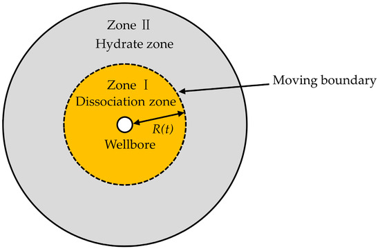
Figure 1.
Schematic of hydrate dissociation in an infinite radially symmetrical region.
In this section, the authors will provide a detailed introduction to the construction of the mathematical model for predicting temperature distribution and dissociation front location. In the whole hydrate reservoir system, the general energy conservation law can be written as [41]:
where and indicate time and the radial coordinate, respectively, is the total energy per gram, is the total energy per unit volume, is the velocity per unit volume, is heat flux rate, and is thermodynamic pressure.
As mentioned in the assumptions, the densities of the dissociation zone (Zone I) and the hydrate zone (Zone II) are constants, but different. Therefore, the velocity must be uniform in each zone. The total energy is the sum of the internal energy , and Equation (1) can be rewritten as:
Since in each zone, it has:
Because du = cdT, we can obtain , , and , where k is thermal conductivity. Equation (3) describing the heat conduction in Zone I () is given as:
and Equation (3) describing the heat conduction in Zone II () is given as:
Noticing that , Equations (4) and (5) can be rewritten as:
and
Let , Equations (6) and (7) can be further rewritten as follows:
and
Because there is a density difference between Zone I and Zone II, the volume change in the dissociation zone leads to a uniform speed. Based on the mass conservation law, a volume of solid hydrates melts in time has:
So,
Let , and it has:
Let . Then is a constant and , which indicates that the bulk water moves slower than the dissociation front.
Substituting Equation (12) into Equations (8) and (9), we can obtain the following heat conduction equation with a density difference:
The initial conditions t = 0, boundary conditions at Zone I () and Zone II () and dissociation front () are as follows:
The location of the dissociation front, which is also known as the Stefan moving boundary, has the following relationship with time during the dissociation process:
We define the similarity variable , where is an undetermined coefficient. Let , and make the self-similar transformation to Equation (13), it has:
where , which is an infinitely small quantity. Meanwhile, at , the boundary conditions are as follows:
The analytical solution of Equations (17) and (18) can be written as:
To get a transcendental equation, we need to calculate the partial derivative of Equation (19) with respect to , which is given as:
Combining Equations (20) and (16), the transcendental equation can be expressed as:
The unique root of Equation (21) can be obtained using numerical iteration. Furthermore, Equation (21) indicates that the value of is related to the heated-water temperature and the hydrate density change.
3. Results and Discussion
Before conducting the investigation, we discuss the effect of density difference on the simulation outputs. Figure 2a presents the comparison between the temperature distributions calculated with the proposed model and the model ignoring density difference. As one can see from this figure, the temperatures calculated with the proposed model are higher than those calculated with the model ignoring density difference. This can be explained as follows: The density difference between the dissociation zone and the hydrate zone can cause a volume change in the dissociation zone, leading to a bulk water velocity. The bulk water produced in the dissociation zone can store energy. Therefore, compared to the temperatures calculated with the model ignoring density difference, the temperatures considering density difference are higher. Figure 2b presents the comparison between the dissociation distances calculated with the proposed model and the model ignoring density difference. In Figure 2b, the dissociation distances calculated with this model are larger than those calculated with the model ignoring density difference. Since the temperature for the scenario considering density difference is higher than that for the scenario ignoring density difference, the dissociation front advances more rapidly, which results in a larger dissociation distance. In practice, the density difference between the dissociation zone and the hydrate zone should be physically present in the hydrate dissociation process. Therefore, the proposed model, which considers the density difference, can provide realistic results.
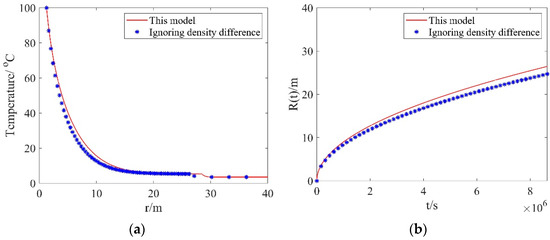
Figure 2.
Comparisons of results from this model and the model ignoring density difference: (a) the temperature distributions; (b) dissociation distances.
In this section, we firstly derive the unique root of the transcendental equation. Subsequently, we study the influence of the initial heated-water temperature and hydrate density on the unique root, dissociation front, and temperature distribution. The following values of parameters are used in the benchmark model [36]: P =5.5 MPa, Ti = 3.5 °C, Tinj = 100 °C, r =100 m, αD = 2.89 × 10⁻⁶ m2/s, αH = 0.697 × 10⁻⁶ m2/s, ρD = 1000 kg/m3, ρH = 914.7 kg/m3, kD = 5.57 W/(m·k), and kH =2.73 W/(m·k). kD is the effective thermal conductivity of the dissociation zone containing solid grains, water, and gas, and kH is the effective thermal conductivity of the hydrate zone containing solid grains and hydrate. Each unit volume of hydrate can dissociate into 0.8 units volume of water and ideal gas. This is ignored; therefore, the pressure change can be neglected when 0.2 units volume of heated-water is injected into the pure hydrate reservoir. We can calculate the dissociation temperature with the method introduced by Deaton [42]:
The latent heat of hydrate can be obtained with the equation introduced by Clausius [43]:
where is the mole number of dissociation gas, is gas deviation factor, MPa·m3/(kmol·K) is a universal gas coefficient.
The transcendental equation (Equation (21)) has a unique root . However, it is difficult to calculate the analytical solution. Therefore, we calculate the unique root of Equation (21) through numerical iteration. We calculate with different values of injection time t (i.e., t = 105 s, 106 s, 107 s), and the results show that remains constant ( = 0.0045), which indicates that the numerical method cannot provide us with an insight into the effect of time on the unique root of Equation (21). As the temperature of the heated-water is increased from 100 °C to 300 °C, is increased from 0.0045 to 0.0048. In addition, is decreased from 0.0053 to 0.0043 as the hydrate densities are increased from 750 kg/m3 to 950 kg/m3.
Based on the analytical solution of temperature (Equation (19)) and the values of , we can draw the temperature distribution of the dissociation zone and hydrate zone at different injection times, different distances, and different densities of hydrate.
Figure 3a shows the temperature distribution along the radial direction with different injection times but a fixed hydrate density. One can see from this figure that the temperature exhibits a rapid decrease from 100 °C (the heated-water temperature) to 5.305089 °C (the hydrate dissociation temperature), and then decreases to the initial reservoir temperature. As the injection time is increased from 105 s to 107 s, the values of the radial dissociation distance R(t) are increased from 2.8460 m to 28.4605 m, which indicates that the dissociation distance increases rapidly. Figure 3b presents the temperature distribution along the radial direction with different hydrate densities but a fixed injection time. As one can see from this figure, with the hydrate density is increased, the dissociation distance gradually decreases. At a hydrate density of 750 kg/m3, the maximum dissociation distance is 10.6 m.
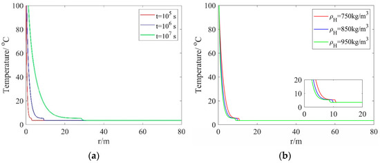
Figure 3.
Temperature distribution along the radial direction: (a) different injection times and a fixed hydrate density; (b) different hydrate densities and a fixed injection time.
Figure 4a shows the reservoir temperature at different radial distances but with a fixed hydrate density. As one can see from this figure, the temperature rises slowly from the reservoir temperature to the hydrate dissociation temperature. Subsequently, the temperature exhibits a rapid increase and approaches the heated-water temperature. As the radial distance is decreased, it takes a longer time to reach the hydrate dissociation temperature. In addition, as the radial distance is increased from 10 m to 20 m, the time taken to reach the hydrate dissociation temperature is increased from 1.2346 × 10⁶ s to 4.9383 × 10⁶ s. This indicates that, the dissociation rate is decreased as the dissociation proceeds. Figure 4b presents the reservoir temperature with different hydrate densities but at a fixed radial distance. As one can see from this figure, a smaller hydrate density can lead to a higher temperature. At a hydrate density of 750 kg/m3, the minimum time taken for the dissociation distance to be 20 m is 3.56 × 10⁶ s.
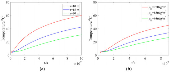
Figure 4.
The reservoir temperature: (a) different radial distances and a fixed hydrate density; (b) different hydrate densities and a fixed radial distance.
Figure 5a shows the radial dissociation distance with different heated-water temperatures but a fixed hydrate density. The dissociation distance calculated with different heated-water temperatures illustrates negligible difference at early times. As the injection time is increased, the difference becomes noticeable, and the dissociation distance tends to be increased as the heated-water temperature is increased, leading to a larger dissociation zone. Figure 5b presents the radial dissociation distance with different hydrate densities but a fixed heated-water temperature. With the injection time unchanged, a smaller hydrate density can result in a larger dissociation distance, which agrees with the results calculated in Figure 4b. The effect of heated-water temperature on the dissociation distance is less noticeable than that of hydrate density.
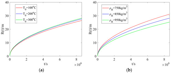
Figure 5.
The radial dissociation distance: (a) different heated-water temperatures and a fixed hydrate density; (b) different hydrate densities and a fixed heated-water temperature.
4. Conclusions
In this work, the authors propose a mathematical model to study hydrate dissociation under thermal stimulation in an infinite radially symmetrical reservoir. The density difference between the dissociation zone and the hydrate zone can cause a volume change in the dissociation zone. The bulk water velocity is determined on the basis of the mass conservation law. The Stefan moving boundary conditions describing the discontinuity phase change interface are innovatively deduced, and analytical solutions to the temperature distribution are derived by using the self-similarity transformation. The unique root of the transcendental equation is presented for the infinite radially symmetrical reservoir example. In addition, the influences of the heated-water temperature and the hydrate density on ξ are studied in detail through numerical iteration. With the aid of the proposed model, the authors investigate the effects of heated-water temperature and hydrate density on temperature distribution and dissociation front location. The calculated results show that the heated-water temperature and hydrate density exert significant influence on the hydrate dissociation. With the injection time unchanged, the dissociation distance tends to be increased as the heated-water temperature is increased, leading to a larger dissociation zone. Additionally, a smaller hydrate density can result in a larger dissociation distance. For hydrate thermal stimulation, a higher heated-water temperature and a lower hydrate density can lead to a larger dissociation distance with the injection time unchanged. As the hydrate dissociation proceeds, the dissociation rate is decreased.
Author Contributions
Formal analysis, W.L.; Methodology, Q.W. and X.F.; Supervision, H.L., B.T. and G.Y.; Writing—original draft, X.F.; Writing—review & editing, Q.W., H.L. and B.T. All authors have read and agreed to the published version of the manuscript.
Funding
This research was funded by the National Natural Science Foundation of China (53200659042), Fundamental Research Funds for the Central Universities (2652020014).
Data Availability Statement
The data presented in this study are available on request from the corresponding author.
Acknowledgments
The authors are grateful to the National Natural Science Foundation of China (53200659042), Fundamental Research Funds for the Central Universities (2652020014).
Conflicts of Interest
The authors declare no conflict of interest.
Nomenclature
| A | average cross-sectional area of the reservoir, m2 |
| cD | specific heat capacity of the dissociation zone, kcal·kg−1·K−1 |
| cH | specific heat capacity of the hydrate zone, kcal·kg−1·K−1 |
| k | thermal conductivity, W·m−1·k−1 |
| kD | effective thermal conductivity of the dissociation zone, W·m−1·k−1 |
| kH | effective thermal conductivity of the hydrate zone, W·m−1·k−1 |
| L | hydrate dissociation latent heat, W·mol−1 |
| m | mass, kg/m3 |
| p | thermodynamic pressure, MPa |
| P | initial reservoir pressure, MPa |
| q | heat flux rate, kJ/m3 |
| r | radial coordinate, m |
| R(t) | location of the dissociation front, m |
| t | time, d |
| T | temperature, °C |
| TD | temperature of the dissociation zone, °C |
| TH | temperature of the hydrate zone, °C |
| Tinj | injected heated-water temperature, °C |
| Ti | initial reservoir temperature, °C |
| Td | hydrate dissociation temperature, °C |
| u | internal energy, kJ |
| v | velocity per unit volume, m/s |
| vD | velocity of the dissociation zone, m/s |
| vH | velocity of the hydrate zone, m/s |
| Δr | length along the radial coordinate, m |
| Δt | time interval, d |
| ρ | density, kg/m3 |
| ρD | density of the dissociation zone, kg/m3 |
| ρH | density of the hydrate zone, kg/m3 |
| ε | total energy per unit mass, kJ/kg |
| α | Thermal diffusion coefficient, μm2·s−1 |
| αD | Thermal diffusion coefficient of the dissociation zone, μm2·s−1 |
| αH | Thermal diffusion coefficient of the hydrate zone, μm2·s−1 |
| λ, ξ, η, rc | defined parameters |
References
- Sloan, E.D. Fundamental Principles and Applications of Natural Gas Hydrates. Nature 2003, 426, 353–359. [Google Scholar] [CrossRef] [PubMed]
- Sun, Q.; Kang, Y.T. Review on CO2 Hydrate Formation/Dissociation and its Cold Energy Application. Renew. Sustain. Energy Rev. 2016, 62, 478–494. [Google Scholar] [CrossRef]
- Yin, Z.; Chong, Z.R.; Tan, H.K.; Linga, P. Review of Gas Hydrate Dissociation Kinetic Models for Energy Recovery. J. Nat. Gas Sci. Eng. 2016, 35, 1362–1387. [Google Scholar] [CrossRef]
- Ruppel, C.D.; Kessler, J.D. The Interaction of Climate Change and Methane Hydrates. Rev. Geophys. 2017, 55, 126–168. [Google Scholar] [CrossRef]
- Farahani, M.V.; Hassanpouryouzband, A.; Yang, J.; Tohidi, B. Insights into the Climate-Driven Evolution of Gas Hydrate-Bearing Permafrost Sediments: Implications for Prediction of Environmental Impacts and Security of Energy in Cold Regions. RSC Adv. 2021, 11, 14334–14346. [Google Scholar] [CrossRef] [PubMed]
- Xu, Q.; Liu, C.; Liu, Q.; Zhu, Y.; Zhou, H.; Guo, L. Interfacial Characteristics of Steam Jet Condensation in Subcooled Water Pipe Flow–An Experimental and Numerical Study. Chem. Eng. Sci. 2022, 251, 117457. [Google Scholar] [CrossRef]
- Xu, Q.; Zhu, Y.; Zhou, H.; She, Y.; Guo, L. Flow Characteristic of Steam Jet Condensed into a Water Pipe Flow-a Numerical Study. Appl. Therm. Eng. 2022, 205, 118034. [Google Scholar] [CrossRef]
- Ghosh, D.; Ghose, J.; Datta, P.; Kumari, P.; Paul, S. Strategies for Phase Change Material Application in Latent Heat Thermal Energy Storage Enhancement: Status and Prospect. J. Energy Storage 2022, 53, 105179. [Google Scholar] [CrossRef]
- Tao, Y.; Liu, Y.; He, Y. Effects of PCM Arrangement and Natural Convection on Charging and Discharging Performance of Shell-and-Tube LHS Unit. Int. J. Heat Mass Transf. 2017, 115, 99–107. [Google Scholar] [CrossRef]
- Lv, S.; Feng, G.; Zhu, N.; Li, D. Experimental Study and Evaluation of Latent Heat Storage in Phase Change Materials Wallboards. Energy Build. 2007, 39, 1088–1091. [Google Scholar]
- Amin, M.; Afriyanti, F.; Putra, N. Thermal Properties of Paraffin Based Nano-Phase Change Material as Thermal Energy Storage. Earth Environ. Sci. 2018, 105, 012028. [Google Scholar] [CrossRef]
- Verigin, N.N.; Khabibullin, I.L.; Khalikov, G.A. Linear Problem of the Dissociation of the Hydrates of a Gas in a Porous Medium. Fluid Dyn. 1980, 15, 144–147. [Google Scholar] [CrossRef]
- Kamath, V.A.; Godbole, S.P. An Analytic Model for Analyzing the Effects of Dissociation of Hydrates on the Thermal Recovery of Heavy Oils. SPE Reserv. Eng. 1988, 3, 449–456. [Google Scholar] [CrossRef]
- Selim, M.S.; Sloan, E.D. Hydrate Dissociation in Sediment. SPE Reserv. Eng. 1990, 5, 245–251. [Google Scholar] [CrossRef]
- Tsypkin, G.G. Effect of Decomposition of a Gas Hydrate on the Gas Recovery from a Reservoir Containing Hydrate and Gas in the Free State. Fluid Dyn. 2005, 40, 117–125. [Google Scholar] [CrossRef]
- Roostaie, M.; Leonenko, Y. Analytical Modeling of Methane Hydrate Dissociation under Thermal Stimulation. J. Pet. Sci. Eng. 2020, 184, 106505. [Google Scholar] [CrossRef]
- Fang, X.; Lian, H.; Luo, W.; Liu, M.; Chen, C.; Wang, Q. Hydrate Dissociation Model with Time Fractional Derivative. Geofluids 2022, 2022, 5598287. [Google Scholar] [CrossRef]
- Li, M.; Fan, S.; Su, Y.; Lu, M. Numerical Modeling of the Physical Parameters of the Heated-Water Dissociation Interface into the Natural Gas Hydrates Reservoir. Appl. Therm. Eng. 2016, 106, 49–55. [Google Scholar] [CrossRef]
- Wang, Y.; Feng, J.; Li, X.; Zhang, Y.; Li, G. Analytic Modeling and Large-Scale Experimental Study of Mass and Heat Transfer during Hydrate Dissociation in Sediment with Different Dissociation Methods. Energy 2015, 90, 1931–1948. [Google Scholar] [CrossRef]
- Roostaie, M.; Leonenko, Y. Analytical Investigation of Gas Production from Methane Hydrates and the Associated Heat and Mass Transfer upon Thermal Stimulation Employing a Coaxial Wellbore. Energy Convers. Manag. 2020, 209, 112616. [Google Scholar] [CrossRef]
- Holder, G.D.; Angert, P.F. Simulation of Gas Production from a Reservoir Containing Both Gas Hydrates and Free Natural Gas. In Proceedings of the SPE Annual Technical Conference and Exhibition, New Orleans, LA, USA, 26–29 September 1982. [Google Scholar]
- Burshears, M.; O’brien, T.J.; Malone, R.D. A Multi-Phase, Multi-Dimensional, Variable Composition Simulation of Gas Production from a Conventional Gas Reservoir in Contact with Hydrates. In Proceedings of the SPE Unconventional Gas Technology Symposium, Louisville, KY, USA, 18–21 May 1986. [Google Scholar]
- Moridis, G.J. Numerical Studies of Gas Production from Methane Hydrates. SPE J. 2003, 8, 359–370. [Google Scholar] [CrossRef]
- Moridis, G.J.; Collett, T.S.; Dallimore, S.R.; Satoh, T.; Hancock, S.; Weatherill, B. Numerical Studies of Gas Production from Several CH4 Hydrate Zones at the Mallik Site, Mackenzie Delta, Canada. J. Pet. Sci. Eng. 2004, 43, 219–238. [Google Scholar] [CrossRef]
- Moridis, G.J.; Sloan, E.D. Gas Production Potential of Disperse Low-Saturation Hydrate Accumulations in Oceanic Sediments. Energy Convers. Manag. 2007, 48, 1834–1849. [Google Scholar] [CrossRef]
- Ahmadi, G.; Ji, C.; Smith, D.H. Numerical Solution for Natural Gas Production from Methane Hydrate Dissociation. J. Pet. Sci. Eng. 2004, 41, 269–285. [Google Scholar] [CrossRef]
- Wang, Y.; Feng, J.; Li, X.; Zhang, Y.; Li, G. Large Scale Experimental Evaluation to Methane Hydrate Dissociation Below Quadruple Point in Sandy Sediment. Appl. Energy 2016, 162, 372–381. [Google Scholar] [CrossRef]
- Wang, Y.; Feng, J.; Li, X.; Zhang, Y.; Chen, Z. Fluid Flow Mechanisms and Heat Transfer Characteristics of Gas Recovery from Gas-Saturated and Water-Saturated Hydrate Reservoirs. Int. J. Heat Mass Transf. 2018, 118, 1115–1127. [Google Scholar] [CrossRef]
- Li, B.; Liu, S.; Liang, Y. Experimental Study of Methane Hydrate Dissociation by Depressurization and Electrical Heating. Energy Procedia 2017, 105, 5018–5025. [Google Scholar] [CrossRef]
- Li, P.; Zhang, X.; Lu, X.; Liu, L.; Liu, C. Study on Gas Hydrate Dissociation in Small Bodies of Hydrate-Bearing Sediments Under Water-Heating Condition. In Proceedings of the 26th International Ocean and Polar Engineering Conference, Rhodes, Greece, 26 June–2 July 2016. [Google Scholar]
- Shi, K.; Wei, R.; Guo, X.; Li, Q.; Lv, X.; Fan, Q.; Dong, H.; Yang, L.; Zhao, J.; Song, Y. Enhancing Gas Production from Hydrate-Bearing Reservoirs Through Depressurization-Based Approaches: Knowledge from Laboratory Experiments. Energy Fuels 2021, 35, 6344–6358. [Google Scholar] [CrossRef]
- Li, X.; Li, X.; Wang, Y.; Liu, J.; Hu, H. The Optimization Mechanism for Gas Hydrate Dissociation by Depressurization in the Sediment with Different Water Saturations and Different Particle Sizes. Energy 2021, 215, 119129. [Google Scholar] [CrossRef]
- Li, X.; Li, X.; Wang, Y.; Zhang, Y.; Wan, K.; Zeng, H. The Consistency of the Normalized Hydrate Dissociation Rate in the Hydrate Simulator with Different Scales. Fuel 2021, 287, 119436. [Google Scholar] [CrossRef]
- Dong, S.; Yang, M.; Chen, M.; Zheng, J.; Song, Y. Thermodynamics Analysis and Temperature Response Mechanism during Methane Hydrate Production by Depressurization. Energy 2022, 241, 122902. [Google Scholar] [CrossRef]
- Jin, G.; Peng, Y.; Liu, L.; Su, Z.; Liu, J.; Li, T.; Wu, D. Enhancement of Gas Production from Low-Permeability Hydrate by Radially Branched Horizontal Well: Shenhu Area, South China Sea. Energy 2022, 253, 124129. [Google Scholar] [CrossRef]
- Li, M.; Fan, S.; Su, Y.; Xu, F.; Li, Y.; Lu, M.; Sheng, G.; Yan, K. The Stefan Moving Boundary Models for the Heat-Dissociation Hydrate with a Density Difference. Energy 2018, 160, 1124–1132. [Google Scholar] [CrossRef]
- Kou, X.; Wang, Y.; Li, X.; Zhang, Y.; Chen, Z. Influence of Heat Conduction and Heat Convection on Hydrate Dissociation by Depressurization in a Pilot-Scale Hydrate Simulator. Appl. Energy 2019, 251, 113405. [Google Scholar] [CrossRef]
- Yang, M.; Zheng, J.; Gao, Y.; Ma, Z.; Lv, X.; Song, Y. Dissociation Characteristics of Methane Hydrates in South China Sea Sediments by Depressurization. Appl. Energy 2019, 243, 266–273. [Google Scholar] [CrossRef]
- Yin, Z.; Wan, Q.; Gao, Q.; Linga, P. Effect of Pressure Drawdown Rate on the Fluid Production Behaviour from Methane Hydrate-Bearing Sediments. Appl. Energy 2020, 271, 115195. [Google Scholar] [CrossRef]
- Ruan, X.; Xu, C.; Yan, K.; Li, X. Experimental and Modeling Study of Kinetics for Hydrate Decomposition Induced by Depressurization in a Porous Medium. Front. Energy Res. 2021, 9, 779635. [Google Scholar] [CrossRef]
- Hahn, D.W.; Özisik, M.N. Heat Conduction, 3rd ed.; John Wiley & Sons, Inc.: Hoboken, NJ, USA, 2012. [Google Scholar]
- Deaton, W.M.; Frost, E.M. Gas Hydrates and Their Relation to the Operation of Natural-Gas Pipe Lines; U.S. Bureau of Mines, Monograph 8; American Gas Association: Washington, DC, USA, 1946. [Google Scholar]
- Clausius, R. Ueber die bewegende Kraft der Wärme und die Gesetze, welche sich daraus für die Wärmelehre selbst ableiten lassen. Ann. Der Phys. 1850, 155, 368–397. (In German) [Google Scholar] [CrossRef]


Publisher’s Note: MDPI stays neutral with regard to jurisdictional claims in published maps and institutional affiliations. |
© 2022 by the authors. Licensee MDPI, Basel, Switzerland. This article is an open access article distributed under the terms and conditions of the Creative Commons Attribution (CC BY) license (https://creativecommons.org/licenses/by/4.0/).