Abstract
Superconducting magnetic energy storage (SMES) systems are characterized by their high-power density; they are integrated into high-energy density storage systems, such as batteries, to produce hybrid energy storage systems (HESSs), resulting in the increased performance of renewable energy sources (RESs). Incorporating RESs and HESS into a DC bus to obtain a DC microgrid concept is considered a more attractive option for solving system reliability and stability issues. In this paper, we focus on employing SMES systems based on their characteristics of a fast response and high efficiency, which contribute to increased battery lifespan, and reducing the mismatch between the energy supplied by the renewable energy source and the load demand by compensating for the effects of partial shading on the PV system on the DC bus side and the imbalance in loads on the other side of the AC bus. The incremental conductance algorithm (INC) is used for maximum power point tracking (MPPT) in the PV system. Fuzzy logic control (FLC) is proposed for the generation of control signals for the DC–DC chopper used to charge/discharge the SMES coil. Simulations using MATLAB/Simulink were then carried out to assess the proposed models of the (standalone and grid) connection systems.
1. Introduction
The rapid expansion and development in all areas of industry and energy marketing have led to an increased demand for electric power to meet the needs of consumers. Electric power stations of a traditional nature, which run on fossil fuels or gas, are usually installed in places far from city centers to reduce the effects on humans of the pollution resulting from combustion processes and noise. In addition, this type of power station requires constant maintenance, large stores for fuel storage, and high transportation costs. The appropriate solution is to rely on renewable energy sources (RESs) such as solar energy photovoltaics (PVs), wind energy wind turbines (WTs), and hydroelectricity energy, which are considered to be inexhaustible and are characterized by abundance, especially PV in sunny countries. In addition, the associated infrastructure can be cheaply manufactured and has low maintenance costs, with a long lifespan of more than 20 years. The future of sustainable energy for electric power systems is that their main components are wind turbines and PV arrays, which aim to limit the greenhouse effect [1,2]. Sustainable energy is very useful in remote areas that are not reached by the main grid [3,4]. Renewable energies, however, usually have low reliability because of the intermittency of energy supply, which depends mainly on climate conditions and its fluctuations and, in the case of hydroelectric energy, on geographical factors, namely water sources. Therefore, it is necessary to solve the problem of reliability associated with natural energy sources by building a hybrid system that combines RESs with ESS and collects energy at a common coupling point (PCC) called the DC bus [5]. Additionally, power electronic components can be used to convert the AC output from WT to DC voltage [6]. ESSs are many and varied, but batteries (BESS) remain to be the most widely used in energy storage applications. The disadvantages of BESS are the restricted number of full discharge cycles, the fact that they are environmentally unfriendly, and that heat can escape with incorrect charging [7,8]. They are affordable in cost and characterized by high-energy density (HED), which is a favorable specification for providing continuous energy in the long term as well as scalability and the possibility of being integrated with other ESS technologies.
In a microgrid system with only one storage system, such as in the case of BESS, negative effects arise when there is a disconnection from the main grid to off-grid, as this will lead to a rapid loss of battery energy due to increased demand, which reduces the battery life. In addition, the inability to supply the system with high power density (HPD) at the beginning of the operation will increase the cost, maintenance, and the amount of pollution, unless a large number of system units are connected in a series to increase their response speed.
It is possible to achieve a suitable system that fulfills the technical and economic requirements by combining two or more storage systems to obtain an HESS with HED and HPD. An HESS system of a BESS/Supercapacitor (SC) was studied by researchers and used in electric vehicles [9] as well as power systems [10]. A study was carried out with an HESS of a BESS/SMES by J Li and applied in an AC electrical power system for frequency regulation [11]. An SMES system provides better power density benefits over SC and other HPD energy storage technologies [7], a low rate of self-discharge [12], and greater capacity to handle a peak current [13]. A hybrid arrangement for SMES/batteries contributes to a reduction in size of the SMES and to the extension of battery life by reducing the number of charge/discharge cycles [14,15]. The main problem in the use of SEMS is the high cost, which is being dramatically reduced as a result of research into the development of materials [16,17].
Recently, many researchers have been attracted to SMES devices, which have been used in various applications, including in the military [18,19], communication, space missions [20], as well as in energy storage [21], stability [22,23], UPS [24], and in combination with smart grids and RESs [25].
Qixing Sun [26] proposed a new system for energy management control based on three input parameters to the FLC system to deal with a high fluctuating power demand by using a hybrid SMES/battery energy system. This study takes into account the SOC of the SMES magnet in addition to the power disparity between battery production and demand. By taking this into account, the control mechanism may be made to work with SMES magnets of any size. According to Rachakonda Shri Rama Akshay [27], STATCOM was combined with the SMES to improve the stability and enhance the power transmission capacity, where a significant improvement was observed in frequency deviations of up to 40%, as well as the settling time and overshoots. To prevent frequency and tie line power excursions, STATCOM controls tie line power while SMES supplies unexpected load needs.
K. Iyswarya Annapoorani [28] alleviated frequency control problems in the isolated MG by integrating the SMES unit and the integrated fuzzy logic controller. Frequency oscillations are caused by fast variations in load and the discontinuous nature of RESs, which are reduced using SMES units.
Ahmed Samawi Alkhafaji [29] conducted a review study on the use of SMES with a PV system to enhance the microgrid and improve the power quality. The study focuses on solutions to the issues of voltage and frequency variations that impact the electrical grid as a result of rising energy consumption and penetrations.
Heba T. K, in [30], proposed a method called Archimedes optimization algorithm (AOA) for optimizing SMES performance and maintaining the stability of wind energy conversion systems, which was used to determine the ideal operating conditions for the PI controller to govern the charging and discharging of the SMES system.
Kotb M. Kotb, in [31], compares the performance of a hybrid renewable PV/wind DC bus microgrid that uses fuzzy-controlled battery and SMES systems in independently improving microgrid stability and power quality.
Jian Xun Jin, in [32], presented a proposed SMES system based on a shunt active power filter (SAPF) to alleviate power variations (PVs) in the microgrid and restrict the unbalanced current and harmonics. It is suggested that a reference current be extracted using the modified ip-iq approach, and an FLC approach was designed to maintain the stability of the DC-link voltage and minimize the depth of discharge of the proposed SMES system.
Hossam S, in [33], proposed an efficient solution to address the problem of intermittent energy sources by coupling to a balanced/unbalanced distribution system utilizing (SMES) technology to minimize frequency and voltage changes during wind tempest. The suggested technique accomplished the grid and common bus power leveling (18 and 33).
Sayed M. Said, in [34], proposed two methods (FLC and OFLC) to optimally compute both the active charging/discharging power of the SMES and the reactive power of the VSC. As a result, the voltage at PCC is controlled, and the tie-line power flow is efficiently reduced. Additionally, there was a considerable reduction in transmission power losses and tie-line power flow variations.
Mohamed Hashem, in [35], suggested the use of a multi-objective-function-based optimization approach with the aim of determining the optimal location and size of WTG and SMES in a distribution system. Based on the standard approach, the IEEE 33-bus was used to test and certify the optimal positioning and size.
Enrique-Luis, in [36], aimed to determine how to employ SMES for energy storage in the future market of electric vehicles and achieved this by taking the requirement for an HESS into consideration. Several legislative solutions, such as the lowering of prices or the encouragement of private investments, have also been considered. In order to minimize greenhouse gases (GHG), it is desirable to capture the market share of various nations.
Ahmed Samawi Alkhafaji, in [37], presented a comprehensive study of HESS system technologies and applications and investigated how these technologies can support microgrid performance as well reduce fossil fuel emissions when integrated with renewable sources.
In previous studies, there has been discussion of the roles of SMES as a storage system integrated with the PV system using different methods. However, changes in temperature (T) and irradiance (Irr), as well as the occurrence of partial shading (PS), which are common, have not been considered.
This paper focuses on the benefits of building an HESS from SMES/battery and their integration with (PV) toward increasing power quality, and thus, improving the performance of microgrids under unbalanced load changes. In this study, we present the problems of the changing intensity of solar radiation and the increase in temperature from the standard values of 25 °C in addition to the problem of partial shading that, when occurring in combination, causes a mismatch between the sources of power generation and the loads or main grid for which the constant voltage and frequency are required. Solving this mismatch problem requires the use of an ESS, which is characterized by high efficiency in power conversion, responsiveness, and a high number of charge and discharge cycles—reasons that collectively results in us preferring SMES over other types of ESSs.
The co-working integration between the SMES and battery allows for reducing the number of batteries and SMES coil size. By using FLC techniques, characterized by their speedy response and efficiency, to control the charge/discharge operation of the SMES coil via controlling the DC–DC chopper, we are able to establish conditions that satisfy power matching.
The proposed model, shown in Figure 1, is designed to cover the energy demand of 10 kW during the daytime, which is an appropriate value for a number of consumers or companies operating in remote areas where the main grid is not available.
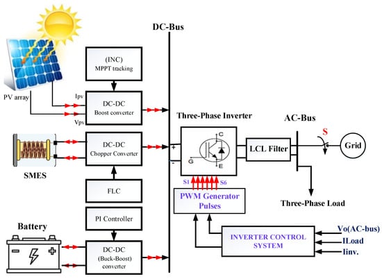
Figure 1.
Block diagram of the model proposed.
In both cases of the standalone or grid connection, the effect of the partial shading condition PSC on PV performance is considered, as well as how it can be compensated with SMES and battery modeling, of which are distinguished by their rapid response and high-power high-energy density to allow for overcoming mismatch problems.
This work is structured as follows: Section 1 is the introduction and literature survey. Section 2 outlines the state of the art for SMES with a system description and HESS control. In Section 3, control techniques are used for managing the source and load sides. Section 4 presents the simulation results and discussion, and the conclusion forms Section 5.
2. State of the Art
2.1. SMES
SMES was initially introduced for electrical power systems in 1961 [38]. The first system of this sort was then constructed in 1981 with the intention of increasing the transmission capacity of transmission lines along the Pacific Ocean, connecting Los Angeles and Washington [39]. When the SMES system was first being developed, all research was concentrated on superconductors that operate at low temperatures (LTS) below 4 K, which needed the expensive and infrequent cooling mechanism known as liquid helium. Long wires, made possible by the discovery of high-temperature superconductors (HTS) in 1986, allowed for a variety of technical applications due to their compatibility with cooling systems that employ liquid nitrogen or helium gas without the requirement for expensive liquid helium. Tampere University of Technology in Finland created the HTS-SMES in 1988. Over 600 chemicals and about 30 metals now include superconductors [40]. The most significant examples are included in Table 1, together with their critical temperatures.

Table 1.
Superconducting materials and their critical temperatures [41].
2.2. System Description and HESS Control Design
Figure 1 shows the integrative installation of the proposed DC microgrid consisting of a photovoltaic array (PV) with SMES and battery ESS devices, with each controlled independently. All are connected to the DC bus, connected to the inverter through a bus capacitor, from the inverter to the LCL filter, and to the AC bus that feeds the loads. The resulting hybrid renewable energy system is based on (MG) its connection to the main grid.
2.2.1. PV System
PV cells may be made in a number of methods using a wide range of materials. Despite these variations, they all carry out the same function—capturing solar energy and turning it into usable power (electrical power). The most typical component used in constructing solar panels is silicon, which possesses semiconducting characteristics [42]. A solar panel is made up of several of these solar cells, whereas a photovoltaic array is made up of numerous solar panels. There are three main types, which are monocrystalline silicon, polycrystalline silicon, and thin film, and these are the most common in the global market of photovoltaic technologies. Examples that are less common, because of high cost but are characterized by high efficiency, include multi-junction cells and gallium arsenide, which are considered ideal, especially when used in space applications and concentrated photovoltaic systems [43].
Photovoltaics, by definition, involves the direct conversion of light to electrical energy when light falls on a solar cell (PV), where it absorbs photons of light and releases electronic charges [44].
The work of solar cells depends on two main elements, solar radiation and temperature, as the performance of the photovoltaic system changes with the change in the weather situation. When the temperature rises above the standard value of 25 °C, the efficiency and capacity of the PV units decrease, whereas the rise in solar radiation increases the produced energy, and thus, increases the PV efficiency, as shown in Figure 2.
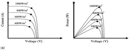
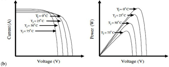
Figure 2.
PV electrical characteristics (a) for the irradiance effect and (b) temperature effect [45].
Figure 3 shows that Ipv−Vpv and Ppv−Vpv curves for various situations serve as generic representations of the electrical characteristics of the PV cell. The specification data of the Soltech-1STH-250 WH module monocrystalline silicon proposed in this work at a rated power of 10 kW are shown in Table 2. It has good efficiency, 80% power output, and a warranty period of 25 years.
Figure 3.
PV array-proposed electrical model c/s.
Table 2.
PV array parameters for the Soltech-1STH-250 WH module.
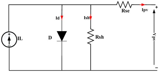
Figure 4.
One-diode PV cell equivalent circuit [46].
Here, IPV and VPV are the O/P current and voltage of PV cell, respectively; IL is the light-generated current; IO is the diode saturation current; q is the electron charge; K is Boltzmann’s constant; T is ambient temperature; and Rsh and Rse are the shunt and series resistors of the PV model, respectively. Equation (2) enables the calculating of the current generated by the radiation falling on the cell and the temperature.
Here, Go is the standard irradiance normally equal to 1000 W/m2, ISTC is the PV current at the standard test conditions, KIsc is the short-circuit current coefficient, Tc is the cell temperature, and Tr is the rated temperature in K°.
The voltage and current produced from the PV array are dependent on the number of modules connected in a series and in parallel:
where Nsc and NPC are the numbers of series and parallel branches in the module, respectively, and MS and MP are the numbers of series and parallel module connections, respectively.
2.2.2. Hybrid Energy Storage Systems (HESS)
The most important support mechanism for incorporating renewable energy sources into the grid is ESS. When the generation and demand sides are flexible, with storage systems acting as the mediators controlling their connectivity, flexibility in power systems can be achieved. Renewable resources can only be used as soon as they become accessible, otherwise, their potential is lost. Additionally, they lack features such as governor controls for regulating frequency and power adjustments because the work depends on the availability of the energy source (climate). ESS assists in removing the grid frequency inertia that prevents RES from quickly recovering from unanticipated changes in demand and supply [47,48]. ESS may support the grid’s higher-level integration of renewable energy. When operating in island mode, the storage system facilitates storing energy for later use, when in abundance, while also ensuring the system’s dependability. However, if a diesel generator is linked to the island-based hybrid system, the storage system may only be employed to maintain the quality of the power for a short time of up to a few minutes while providing smooth support to achieve generation/load balance.
ESS is usually connected with microgrids of two types. The first is HPD, to cover the energy demand during rapid load fluctuations or transit, which usually has a speedy response, high efficiency, and significant life cycle. The other type is HED, which deals with the power demands of a long duration. Three main topologies are used to connect an HESS to a DC bus (passive, semi-active, and active), as shown in Figure 5, and active topology is used in the model proposed for an HESS connection.
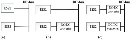
Figure 5.
HESS structure: (a) passive, (b) semi-active, and (c) active.
3. Proposed Control Techniques
Figure 1 shows the basic parts of the proposed system, and each requires an appropriate technique for control. There are four types of control systems used: three for the DC-bus-side devices (PV, battery, and SMES) and one is the inverter on the AC side.
3.1. PV Boost/MPPT Control and Design
Figure 6 shows the PV boost converter used to step up the voltage produced from the PV system. The MPPT algorithm is used to generate the triggering pulses for IGBT.
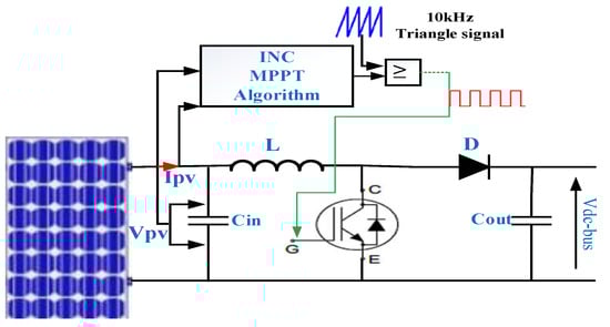
Figure 6.
PV boost converter with MPPT.
The incremental conductance (INC) methodology is one of the most used MPPT methods because of its excellent tracking accuracy in steady state and capacity to adapt to quickly changing atmospheric conditions [49]. The P–V curve slope is identified via the incremental conductance method, and the MPP is monitored by looking for the peak of the P–V curve. For MPPT, this technique employs the incremental conductance dI/dV and instantaneous conductance I/V. Equations (5) and (6) [50] illustrate the INC strategy by applying the critical set criterion of the derivatives to the PV output power.
It is possible to locate the PV module’s operating point on the P–V curve, i.e., (6) the PV module works at the MPP, and (7) and (8) indicate the operation point located on the right and left side of the MPP, respectively. The improve INC algorithm implementation steps, used to track the MPP with an update step, ∆D equal to (0.1 × 10⁻³), are shown in the flowchart shown in Figure 7 [51].
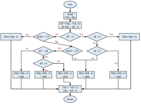
Figure 7.
Improve INC algorithm flowchart for MPPT [51].
We used GT40T301IGBT, which has the rated characteristics of the voltage and current rating (1500 V, 40 A), high speed (tf = 0.25 μs, trr = 0.7 μs), and collector power dissipation of 200 watt at 25 °C. The boost converter specifications of the design can be found in Table 3. The input voltage and current to the boost converter is VPV and IPV, the output voltage and current is VDC−bus and Iboost, and Equations (9) and (10) [52] are used to calculate boost converter parameters L and Cout, respectively. For Cin, a high value is usually selected (1000 μF), which is used as a buffer to keep the DC link voltage constant.
Table 3.
Boost converter design specifications.
3.2. BESS Design and Control
A buck–boost bidirectional converter is used to control the power transmitted between the DC bus and battery and to maintain the DC bus voltage constant throughout various instabilities in order to regulate its duty cycle and subsequently provide appropriate switching pulses. The charging and discharging process is adopted by the bidirectional buck–boost converter to manage battery power considering the difference between the amount of energy generated and the power required by the loads, which is sensed by the control circuit in the presence of a difference in voltage level given the actual DC bus value and the reference value. The working mechanism of the charging (buck) is as follows: The solar energy production exceeds the load demand, which leads to a rise in the actual voltage of the DC bus, and the control circuit then controls the value of the duty cycle (D) between these two values (0 to1) by sensing the DC bus voltage and compares this with the required reference voltage in addition to comparing the actual battery current and reference current. When D is less than 0.5, the buck converter operates to charge the battery, and in this case, the excess power is transmitted from the DC bus to the battery until equalizing the DC bus voltage to the reference voltage; vice versa, when the PV capacity decreases, the voltage of the DC bus decreases, and the D value in the controller system changes to more than 0.5 and less than 1, thereby activating the boost converter (discharge) for the purpose of enhancing energy and filling the shortage. Figure 8, shown below, illustrates the battery charge/discharge system with the control circuit PI controller that is used.
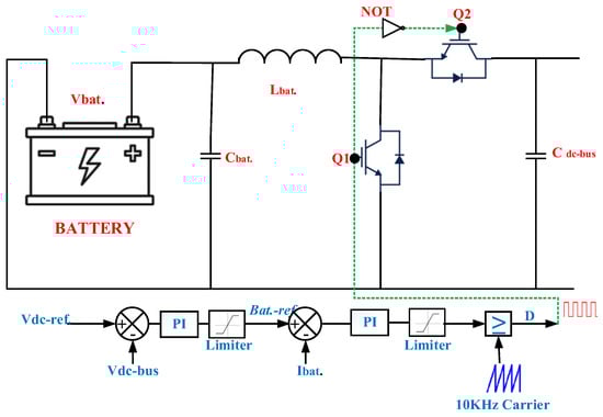
Figure 8.
Control system for a battery.
The battery control system is dependent on a number of parameters: Ibat., Vbat., and state of charge SOC. The buck–boost circuit design is required to determine Cbat. and Lbat. The regulation of the charge/discharge operation uses Equations (11) and (12) [52]. Table 4 shows the battery specification design.
Table 4.
Battery specification information of the design.
A PI controller is utilized as a feedback compensation control in many industrial applications. The battery charging/discharging control system uses a two-loop PI structure, with the internal loop controlling the battery current and the external loop controlling the DC bus voltage. Based on the Ziegler–Nichols method, PI1 and PI2 were calculated, and the tuned controller parameters known by proportional and integral gains (Kp, Ki) are listed in Table 5.
Table 5.
PI controller gain.
3.3. SMES System Design and Control
The SMES magnet, which is utilized to store energy, is controlled by the DC chopper (D chopper or two-quadrant type—B chopper), as shown in Figure 9. FLC has been suggested for managing the process of controlling the operation of the DC chopper because FLC has many advantages, such as a high response with a robust prediction that serves many applications in the field of electric power. The principle of SMES control work is in accordance with the procedure that was followed in the battery, which is based on the difference between the generated power and the load demand that is sensed through a decrease or increase in the DC bus voltage.
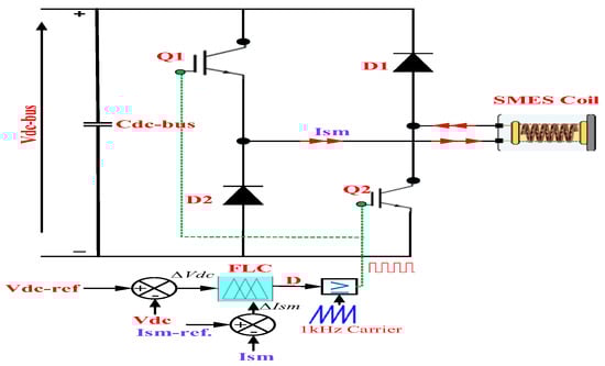
Figure 9.
SMES control system based on FLC.
There are three modes that describe the SMES operation: (a) charge mode, (b) discharge mode, (c) and standby mode, as shown in Figure 10. These three modes are obtained by controlling the (D) value for the DC–DC chopper. In charge mode, (D) fluctuates (D > 0.5 to D < 1), and in this case, Q1 and Q2 are switched on; the power exchange is from the DC bus to the SMES coil at this time, the charge current passes in the positive direction, and the SMES voltage is (+Vsm), as observed in Figure 10a. In the discharge mode, (D) is less than 0.5, and in this case, the DC bus voltage becomes less than the reference voltage so Q1 and Q2 are switched off, the SMES releases the storage energy to the DC bus through D1and D2, and the voltage across the SMES is negative (−Vsm), as seen in Figure 10b. In the third mode, (D) is equal to 0.5, and in this case, the energy remains stored in the SMES coil, and the current circulates between Q1 and D1 or between Q2 and D2, as shown in Figure 10c.
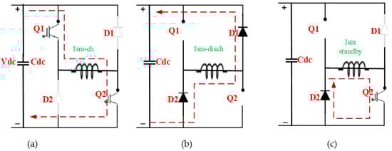
Figure 10.
SMES operation modes: (a) charge mode, (b) discharge mode, and (c) standby mode.
SMES energy storage and power can be calculated.
In the charge mode, the current passing in SMES coil has the expression [29,53]
In the steady state,
Io is the initial SMES current.
In terms of duty cycle (D), the voltage across SMES is
The discharge current is
In this article, the SMES coil is designed with parameters of 50 kJ, 200 A initial current, and 2.5 H. The DC bus capacitor is equal to 2200 µf if calculated with respect to Equation (18) [54], where it is assumed that the DC bus voltage ripple does not exceed 1%.
The coordination of control and management between the PV system and the ESS can be summarized as follows:
- (i)
- When the power characteristic Ppv = Pload, the desired VDC−bus in this case is equal to the Vdc reference, and the storage system is in standby mode, with no exchange of power; ∆Vdc in the control system equals zero and bus regulation is by only the PV system.
- (ii)
- When the error voltage becomes positive (high), this indicates that the VDC−bus is swelling, so the surplus power is absorbed from the SMES coil, the power characteristic is Ppv − Psm = Pload, and bus regulation is based on the SMES.
- (iii)
- When the error voltage becomes more positive (higher), the surplus power is absorbed from BESS in this case, and the power characteristic is Ppv − Pbat. = Pload, and bus regulation is based on the battery.
- (iv)
- When the error voltage becomes negative (low), this indicates that the VDC−bus is sagging (dropping), and the power characteristic is Ppv + Psm = Pload. In this case, the SMES coil injects power into the DC bus.
- (v)
- When the error voltage becomes more negative (lower), this indicates that the VDC−bus is dropping, and the power characteristic is Ppv + Pbat. = Pload. In this case, the battery injects power into the DC bus.
3.4. Inverter Control and LCL Filter Design
3.4.1. Inverter Control
A three-phase inverter is used to convert the form of power from DC power supplied from the DC bus to AC power and then fed to the loads where the inverter is considered to be a separation stage between the generated power (from RESs) and the load or grid. At the start of the design, it is required that the input DC voltage to the inverter is relatively large in order to deal with sudden changes that may occur on the load, and the current output from the inverter can thus accurately track the reference current.
There are three common inverter topologies used to connect the distributed generation (DG) represented by the microgrid to the main grid: standalone (off-grid), on-grid, and hybrid. Each has its own specific control system. In the standalone mode, the inverter control topology is known by voltage control, which means that the output actual voltage is compared with the reference voltage based on (dq synchronous reference frame), as shown in Figure 11, which is the proposed inverter control circuit to generate the PWM signals. In this mode, the power generated by the PV system is proportional to the power required by the loads as well as the SMES/battery ESS systems enabled in off-grid mode to achieve high stability, providing voltage and frequency support with the advantages of inverters to control the output and make it stable, especially when starting the microgrid operation.
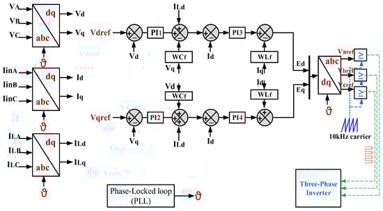
Figure 11.
Inverter control system for the standalone mode.
In the on-grid mode, the energy system (inverter) operates together with the main grid. This type of connection is widely used with RESs, due to its importance with regard to power quality and safety of the grid in addition to ensuring the performance and efficiency of a power system. To meet these criteria, a grid synchronization method and a high-performance current controller are necessary. Figure 12 shows the inverter control strategy, which is the following grid connection. The third connection mode involves a hybrid microgrid that combines on-grid and off-grid, as mentioned above. The synchronization approach is one of the main technological obstacles to grid integration. It is utilized to obtain the appropriate output voltage with increased stability of the power transfer during power sharing. The robust PQPLL, depicted in Figure 13, has been designed to address this problem. This technology uses the tracking method for the purposes of synchronization and balancing between the load or the grid and the source and to ensure the compatibility of the phase sequence.
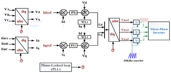
Figure 12.
Inverter control system for the grid-connected mode.
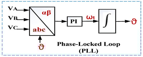
Figure 13.
PLL schematic.
The inverter and LCL filter are connected together on the load side. When the system works in the standalone mode, the capacitor voltage is identical to the reference voltage. In this case, the inverter control system consists of two feedback loops (external and internal loop). In the external loop, the reference voltage and desired load voltage are compared, and the resulting error is corrected by using PI1 and PI3. In the internal loop, the reference current and the actual load current are compared, and the resulting error is corrected by using PI2 and PI4 based on the Ziegler–Nichols method Table 6.
Table 6.
Inverter PI controller gain.
3.4.2. LCL Filter Design
According to the IEEE-519-1992-2014 standard, the LCL filter parameters shown in Figure 14 are calculated as follows.
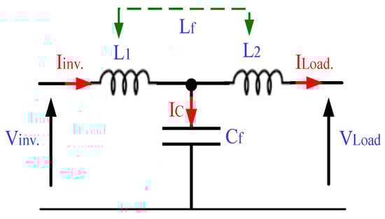
Figure 14.
LCL filter.
VLf = 20% VLoad or Vgrid.
Q = 5% S, IEEE standard, S = 10 kVA, Q = 500/3 VAr/phase, Cf = 10 µf, Lfmax = 10.1 mH = L1 + L2.
4. Simulation Results and Discussion
MATLAB/2020a is used to simulate a microgrid model for the standalone and grid connection shown in Figure 15, which is designed from a PV system with an HESS connected all together with a DC bus. The data used as input for the PV system are taken from the geographical information system [55]. The values of Irr and T are for one day in September for a period of 10 h. In the simulation program, each hour is represented by 0.5 s in order to speed up the program.
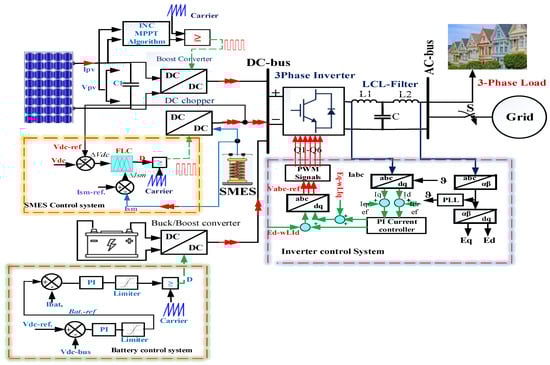
Figure 15.
Simulation of the proposed microgrid model.
4.1. Result 1: Standalone Mode
Case A: In this case, a three-phase inductive load is connected to the AC bus, and the loads change in magnitude and from a balanced to unbalanced condition. The generation of PV power depends on two factors, irradiance (Irr) and (T); thus, the changes in PV power are usually related to neutral weather conditions. The active and reactive load power specifications are listed in Table 7.
Table 7.
Load power specifications for standalone and grid modes.
In Figure 16, the observed DC bus output results for the PV system and HESS are shown. Where the DC bus voltage is matched with the reference value and the voltage ripple is less than 1%, there is a rapid rise in time, the settling time is less than 0.25 s, ∆SOC does not exceed 0.01, and the PV power curve matches the irradiance curve. The loss in power as a result of the temperature rise above the reference of 25 °C is taken into account.
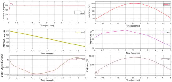
Figure 16.
DC bus output results for the standalone mode.
Figure 17 shows the output load voltage and current in addition to the inverter current; the load voltage is not affected by the load change in value and form, which means that the inverter control system exhibits a robust operation. In addition, the load current is changing, smoothening from unbalance to balance and vice versa. Figure 18 presents the active load power; it is reactive with a smooth change and a load-demand change. The THD is tested in the inverter terminal, and the load result is obtained according to standard value percentages (10.82 and 0.9, respectively) that are not exceeded (Figure 19).
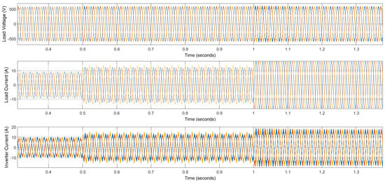
Figure 17.
Load voltage, load, and inverter currents for the standalone mode.
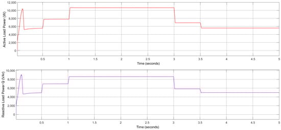
Figure 18.
Active and reactive load power for the standalone mode.
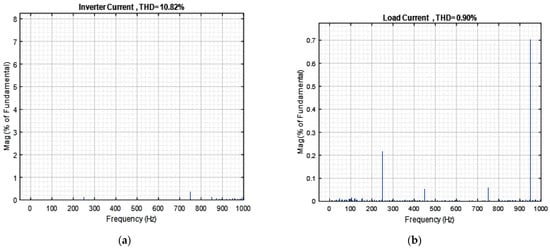
Figure 19.
THD: (a) inverter current and (b) load current for the standalone mode.
Case B: Load Changing and Partial Shading Condition (PSC).
Partial shadowing (PS) occurs when certain PV system cells or modules are partially or completely shadowed due to wear and tear, damage, dust, daytime moving clouds, or nearby structures such as towers or buildings [56,57]. In this case, the effect will manifest in the load profile; the first state is 4.915 KW (0–0.5 s) and increases to 6.538 kW (0.5 to 1 s), where the load is unbalanced, and the balance load is 9.830 kW from 1–3 s. At this time, PS occurs and reduces the solar irradiance from 955 to 300–986 kW/m2 at time 2 to 2.5 to 3 s. As shown in Figure 20, the DC bus voltage is still constant with an expected ∆V of less than 1%, and the PV power is tracking the solar irradiance. Hence, in the shading period, the superconducting coil will immediately compensate for the power shortage. At the same time, the battery SOC will not change.
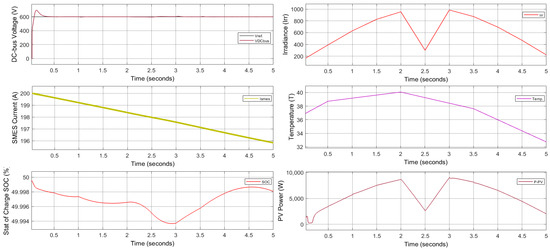
Figure 20.
DC bus output results at PSC.
Figure 21a,b show the load profile result with all changes from an unbalanced inductive load to balanced and vice versa, where the load voltage remains constant and smooth, and the load current response also matches smoothly with load-demand changes. The smooth active and reactive power all change with rms values of 7.549 kW and 7.045 kVAr (Figure 22), and the inverter also maintains its good performance with acceptable THD (Figure 23).
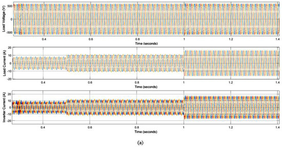
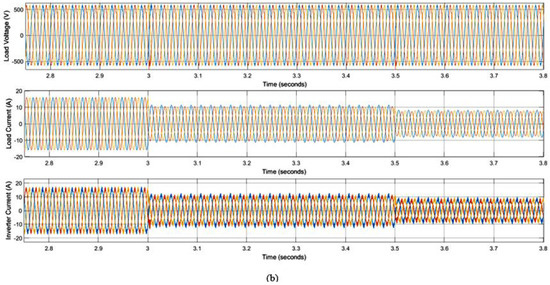
Figure 21.
(a,b) Load voltage, load current, and inverter current at PSC.
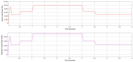
Figure 22.
Active and reactive load power.
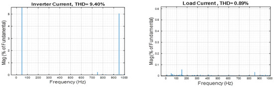
Figure 23.
THD for inverter and load currents at PSC.
4.2. Result 2: Grid-Connected Model
A hybrid system is produced by combining the main grid and microgrid system together. In this system, the SMES/battery storage system provides further support for both systems to maintain power quality and electricity sustainability.
Case A: In this case, in the variable load condition, there is an increase or decrease in the energy demand. The reliability of power availability is increased in the grid connection mode. On the other hand, in the event of grid connection failure, highly efficient storage systems operate to rapidly compensate for energy, thus, maintaining the continuity of the system in operating normally.
Figure 24 shows the DC bus output results represented by the DC bus voltage, with very smooth and fixed levels, everywhere despite all the load changes and the rising and declining irradiance and temperature. ∆SOC is less than 0.005, and the PV power curve smoothly matches the Irr curve changes.
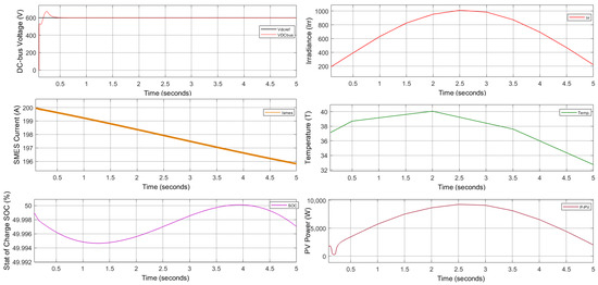
Figure 24.
DC bus output results for the grid mode.
Figure 25 shows that the load voltage is synchronous with the grid voltage and is more smooth compared with that of the standalone system. Figure 26 also shows that the load power is smoother than that for the standalone system, with no overshooting at the start.
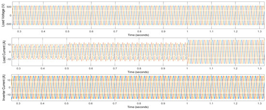
Figure 25.
Load voltage, load current, and inverter current; at the grid mode.
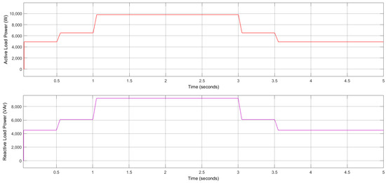
Figure 26.
Active and reactive load power, grid mode.
The load current and inverter current are seamlessly changing, and this is demonstrated by the results of the FFT analysis for THD (3.80% for inverter current and 0.02% for load current), as shown in Figure 27 below.
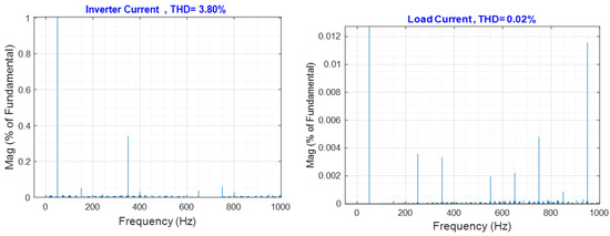
Figure 27.
THD for inverter and load currents; grid mode.
Case B: PSC with grid-connected model.
In this case, the effect of the PSC will be discussed for when the system is connected to the grid. Figure 28 shows the DC bus results and Irr affected by the shading in the time period of 2–3 s. The PV power curve is changing with Irr, and the DC bus voltage remains constant and matches with the reference voltage. The storage energy in the SMES coil is usually exchanged with the DC bus, thus, maintaining the battery’s state of charge, of which is almost constant at 50%. Hence, the good MG performance is based on the SMES/battery system, enhancing the power quality on the load side to obtain a constant load voltage, smooth load change current, seamless grid transient mode, and low HTD.
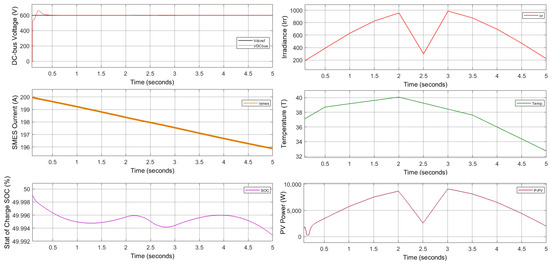
Figure 28.
DC bus output results, grid mode at PSC.
Finally, we conclude that the grid connection has more advantages compared with the standalone model in the center of cities, but in rural areas, the standalone model is more suitable for filling the shortfall in energy demand at less cost with respect to the transmission line installation service (Figure 29, Figure 30 and Figure 31).
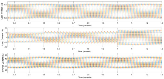
Figure 29.
Load voltage, load current, and inverter current; grid mode at PSC.
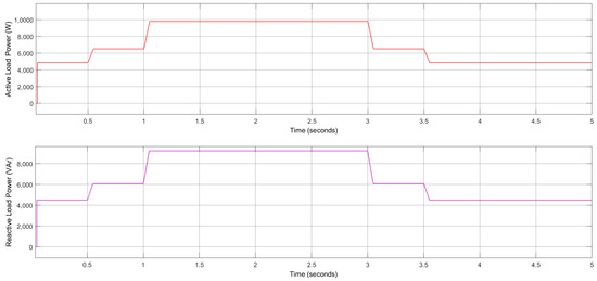
Figure 30.
Active and reactive load power, grid mode at PSC.
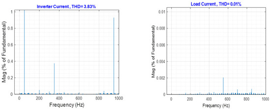
Figure 31.
THD for inverter and load currents; grid mode at PSC.
5. Conclusions
In this paper, the performance of a microgrid under unbalanced inductive loads and PSC is assessed. First, we conclude that the MG reliability increases with HESS for both proposed models (standalone and with grid connection) to provide for the PV generator system based on the SMES/battery in compensating for the shortage in power. Second, the rapid SMES response increases the rise time response to less than 10 ms and the settling time to less than 0.25 s. This is helpful when there are changing loads and PSC, thus, increasing the robustness of the DC bus voltage and keeping it equal to the reference as well as extending the battery lifetime and allowing for a reduction in size. FLC techniques were used to control the DC chopper converter process for charging and discharging the SMES coil through two input parameters: (i) deviation in the DC bus voltage (∆VDC−bus) and (ii) SMES current (∆Ismes). Third, the capacity of the SMES unit to effectively enhance MG performance by reducing the mismatch in power between the intermittent natural source and load was demonstrated, with the positive indication that battery SOC is approximately constant at 50% when PSC occurs at t = 2–3 s. SOC remained constant, which means that the SMES has good performance as an energy compensator. Finally, we achieved the smoothing of active and reactive load power with low THD (0.9% and 0.02%) in standalone and grid modes, respectively, for the load current. There is flexibility and a seamless transition between the standalone mode to grid mode. We conclude that using the SMES/battery system is more effective than using the battery alone to deal with the transient issues of microgrids in a timely manner.
Author Contributions
Original draft preparation; writing—review and editing, supervision, investigation, visualization by A.S.A. The paper has been read and approved by H.T. All authors have read and agreed to the published version of the manuscript.
Funding
This research received no external funding.
Data Availability Statement
Not applicable.
Acknowledgments
The authors extend their appreciation to the University of Sfax and University of Babylon for support this work.
Conflicts of Interest
The authors declare no conflict of interest.
References
- Chen, S.; Liu, P.; Li, Z. Low Carbon Transition Pathway of Power Sector with High Penetration of Renewable Energy. Renew. Sustain. Energy Rev. 2020, 130, 109985. [Google Scholar] [CrossRef]
- Global, E. Outlook 2019: Scaling up the Transition to Electric Mobility, May 2019; International Energy Agency: Paris, France, 2019. [Google Scholar]
- Chaouachi, A.; Kamel, R.M.; Andoulsi, R.; Nagasaka, K. Multiobjective Intelligent Energy Management for a Microgrid. IEEE Trans. Ind. Electron. 2012, 60, 1688–1699. [Google Scholar] [CrossRef]
- Mansour-Saatloo, A.; Agabalaye-Rahvar, M.; Mirzaei, M.A.; Mohammadi-Ivatloo, B.; Abapour, M.; Zare, K. Robust Scheduling of Hydrogen Based Smart Micro Energy Hub with Integrated Demand Response. J. Clean. Prod. 2020, 267, 122041. [Google Scholar] [CrossRef]
- Juma, M.I.; Mwinyiwiwa, B.M.M.; Msigwa, C.J.; Mushi, A.T. Design of a Hybrid Energy System with Energy Storage for Standalone DC Microgrid Application. Energies 2021, 14, 5994. [Google Scholar] [CrossRef]
- Lonkar, M.; Ponnaluri, S. An Overview of DC Microgrid Operation and Control. In Proceedings of the IREC2015 The Sixth International Renewable Energy Congress, Sousse, Tunisia, 24–26 March 2015; pp. 1–6. [Google Scholar]
- Farhadi, M.; Mohammed, O. Energy Storage Technologies for High-Power Applications. IEEE Trans. Ind. Appl. 2015, 52, 1953–1961. [Google Scholar] [CrossRef]
- Jing, W.; Lai, C.H.; Wong, W.S.H.; Wong, M.L.D. A Comprehensive Study of Battery-Supercapacitor Hybrid Energy Storage System for Standalone PV Power System in Rural Electrification. Appl. Energy 2018, 224, 340–356. [Google Scholar] [CrossRef]
- Castaings, A.; Lhomme, W.; Trigui, R.; Bouscayrol, A. Comparison of Energy Management Strategies of a Battery/Supercapacitors System for Electric Vehicle under Real-Time Constraints. Appl. Energy 2016, 163, 190–200. [Google Scholar] [CrossRef]
- Yuan, Y.; Sun, C.; Li, M.; Li, Q. Determination of Optimal Supercapacitor-Lead-Acid Battery Energy Storage Capacity for Smoothing Wind Power Using Empirical Mode Decomposition and Neural Network. Electr. Power Syst. Res. 2015, 127, 323–331. [Google Scholar] [CrossRef]
- Li, J.; Xiong, R.; Yang, Q.; Liang, F.; Zhang, M.; Yuan, W. Design/Test of a Hybrid Energy Storage System for Primary Frequency Control Using a Dynamic Droop Method in an Isolated Microgrid Power System. Appl. Energy 2017, 201, 257–269. [Google Scholar] [CrossRef]
- Bizon, N. Effective Mitigation of the Load Pulses by Controlling the Battery/SMES Hybrid Energy Storage System. Appl. Energy 2018, 229, 459–473. [Google Scholar] [CrossRef]
- Coelho, V.N.; Coelho, I.M.; Coelho, B.N.; de Oliveira, G.C.; Barbosa, A.C.; Pereira, L.; de Freitas, A.; Santos, H.G.; Ochi, L.S.; Guimarães, F.G. A Communitarian Microgrid Storage Planning System inside the Scope of a Smart City. Appl. Energy 2017, 201, 371–381. [Google Scholar] [CrossRef]
- Guo, Q.; Zhang, P.; Bo, L.; Zeng, G.; Li, D.; Fan, J.D.; Liu, H. An Application of High-Temperature Superconductors YBCO to Magnetic Separation. Int. J. Mod. Phys. B 2017, 31, 1745001. [Google Scholar] [CrossRef]
- Ichinose, A.; Horii, S.; Doi, T. Possibility of Material Cost Reduction toward Development of Low-Cost Second-Generation Superconducting Wires. Jpn. J. Appl. Phys. 2017, 56, 103101. [Google Scholar] [CrossRef]
- Shawyer, R. Second Generation EmDrive Propulsion Applied to SSTO Launcher and Interstellar Probe. Acta Astronaut. 2015, 116, 166–174. [Google Scholar] [CrossRef]
- Gubser, D.U. Superconductivity Research and Development: Department of Defense Perspective. Appl. Supercond. 1995, 3, 157–161. [Google Scholar] [CrossRef]
- Shimizu, T.; Underwood, C. Super-Capacitor Energy Storage for Micro-Satellites: Feasibility and Potential Mission Applications. Acta Astronaut. 2013, 85, 138–154. [Google Scholar] [CrossRef]
- Patel, M.R. Spacecraft Power Systems; CRC Press: Boca Raton, FL, USA, 2004; ISBN 0429124112. [Google Scholar]
- Jin, J.X. HTS Energy Storage Techniques for Use in Distributed Generation Systems. Phys. C Supercond. 2007, 460, 1449–1450. [Google Scholar] [CrossRef]
- Yang, J.; Zhang, L.; Wang, X.; Chen, L.; Chen, Y. The Impact of SFCL and SMES Integration on the Distance Relay. Phys. C Supercond. Appl. 2016, 530, 151–159. [Google Scholar] [CrossRef]
- Ali, M.H.; Wu, B.; Dougal, R.A. An Overview of SMES Applications in Power and Energy Systems. IEEE Trans. Sustain. Energy 2010, 1, 38–47. [Google Scholar] [CrossRef]
- Ren, L.; Tang, Y.; Shi, J.; Dou, J.; Zhou, S.; Jin, T. Techno-Economic Evaluation of Hybrid Energy Storage Technologies for a Solar–Wind Generation System. Phys. C Supercond. 2013, 484, 272–275. [Google Scholar] [CrossRef]
- Dufo-López, R.; Lujano-Rojas, J.M.; Bernal-Agustín, J.L. Comparison of Different Lead–Acid Battery Lifetime Prediction Models for Use in Simulation of Stand-Alone Photovoltaic Systems. Appl. Energy 2014, 115, 242–253. [Google Scholar] [CrossRef]
- Li, N.; Chen, Z.; Ren, W.; Li, F.; Cheng, H.-M. Flexible Graphene-Based Lithium Ion Batteries with Ultrafast Charge and Discharge Rates. Proc. Natl. Acad. Sci. USA 2012, 109, 17360–17365. [Google Scholar] [CrossRef]
- Sun, Q.; Xing, D.; Yang, Q.; Zhang, H.; Patel, J. A New Design of Fuzzy Logic Control for SMES and Battery Hybrid Storage System. Energy Procedia 2017, 105, 4575–4580. [Google Scholar] [CrossRef]
- Akshay, R.S.R.; Abraham, R.J. Load Following Performance in a Deregulated Power System with Static Synchronous Compensator and Super Magnetic Energy Storage. Energy Syst. 2022, 1–20. [Google Scholar] [CrossRef]
- Annapoorani, K.I.; Rajaguru, V.; Padmanabhan, S.A.; Kumar, K.M.; Venkatachalam, S. Fuzzy Logic-Based Integral Controller for Load Frequency Control in an Isolated Micro-Grid with Superconducting Magnetic Energy Storage Unit. Mater. Today Proc. 2022, 58, 244–250. [Google Scholar] [CrossRef]
- Alkhafaji, A.S.; Trabelsi, H. Survey a Superconducting Magnetic Energy Storage SMES with PV System to Enhance the Microgrid. In Proceedings of the 2022 19th International Multi-Conference on Systems, Signals & Devices (SSD), Setif, Algeria, 6–10 May 2022. [Google Scholar]
- Abdelbadie, H.T.K.; Taha, A.T.M.; Hasanien, H.M.; Turky, R.A.; Muyeen, S.M. Stability Enhancement of Wind Energy Conversion Systems Based on Optimal Superconducting Magnetic Energy Storage Systems Using the Archimedes Optimization Algorithm. Processes 2022, 10, 366. [Google Scholar] [CrossRef]
- Kotb, K.M.; Elmorshedy, M.F.; Salama, H.S.; Dán, A. Enriching the Stability of Solar/Wind DC Microgrids Using Battery and Superconducting Magnetic Energy Storage Based Fuzzy Logic Control. J. Energy Storage 2022, 45, 103751. [Google Scholar] [CrossRef]
- Jin, J.X.; Wang, J.; Yang, R.H.; Zhang, T.L.; Mu, S.; Fan, Y.J.; Xing, Y.Q. A Superconducting Magnetic Energy Storage with Dual Functions of Active Filtering and Power Fluctuation Suppression for Photovoltaic Microgrid. J. Energy Storage 2021, 38, 102508. [Google Scholar] [CrossRef]
- Salama, H.S.; Vokony, I. Voltage and Frequency Control of Balanced/Unbalanced Distribution System Using the SMES System in the Presence of Wind Energy. Electricity 2021, 2, 205–224. [Google Scholar] [CrossRef]
- Said, S.M.; Ali, A.; Hartmann, B. Tie-Line Power Flow Control Method for Grid-Connected Microgrids with SMES Based on Optimization and Fuzzy Logic. J. Mod. Power Syst. Clean Energy 2020, 8, 941–950. [Google Scholar] [CrossRef]
- Hashem, M.; Abdel-Salam, M.; El-Mohandes, M.T.; Nayel, M.; Ebeed, M. Optimal Placement and Sizing of Wind Turbine Generators and Superconducting Magnetic Energy Storages in a Distribution System. J. Energy Storage 2021, 38, 102497. [Google Scholar] [CrossRef]
- Molina-Ibáñez, E.-L.; Rosales-Asensio, E.; Pérez-Molina, C.; Pérez, F.M.; Colmenar-Santos, A. Analysis on the Electric Vehicle with a Hybrid Storage System and the Use of Superconducting Magnetic Energy Storage (SMES). Energy Rep. 2021, 7, 854–873. [Google Scholar] [CrossRef]
- Alkafaji, A.S.; Al-Samawi, A.A.; Trabelsi, H. Hybrid Energy Storage Review for Renewable Energy System Technologies and Applications. In Proceedings of the 2021 18th International Multi-Conference on Systems, Signals & Devices (SSD), Monastir, Tunisia, 22–25 March 2021; pp. 1059–1067. [Google Scholar]
- Luongo, C.A. Superconducting Storage Systems: An Overview. IEEE Trans. Magn. 1996, 32, 2214–2223. [Google Scholar] [CrossRef]
- Boffmann, E.; Alcorn, J.; Chen, W.; Hsu, Y.; Purcell, J.; Schermer, R. Design of the BPA Superconducting 30-MJ Energy Storage Coil. IEEE Trans. Magn. 1981, 17, 521–524. [Google Scholar] [CrossRef]
- Sharma, A. Properties & Applications of Superconductors. Available online: https://www.yourelectricalguide.com/2019/07 (accessed on 26 September 2022).
- Ilieva, K.; Dinolov, O. State-of-the-Art of Superconducting Materials and Their Energy-Efficiency Applications. In Proceedings of the 2020 7th International Conference on Energy Efficiency and Agricultural Engineering, EE and AE 2020, Ruse, Bulgaria, 11–13 June 2020; pp. 10–14. [Google Scholar] [CrossRef]
- Peake, S. Renewable Energy: Power for a Sustainable Future, 4th ed.; Oxford University Press: Oxford, UK, 2018. [Google Scholar]
- Rekioua, D.; Matagne, E. Optimization of Photovoltaic Power Systems Modelization, Simulation and Control; Springer: Berlin/Heidelberg, Germany, 2012. [Google Scholar]
- Lalouni, S.; Rekioua, D.; Rekioua, T.; Matagne, E. Fuzzy logic control of standalone photovoltaic system with battery storage. J. Power Sources 2009, 193, 899–907. [Google Scholar] [CrossRef]
- Eltamaly, A.M. Performance of MPPT Techniques of Photovoltaic Systems Under Normal and Partial Shading Conditions; Elsevier Inc.: Amsterdam, The Netherlands, 2018; Volume 1, ISBN 9780128132173. [Google Scholar]
- Fathima, A.H.; Palanisamy, K. Energy storage systems for energy management of renewables in distributed generation systems. In Energy Management of Distributed Generation Systems; Mihet-Popa, L., Ed.; Books on Demand: Norderstedt, Germany, 2016. [Google Scholar]
- Yekini Suberu, M.; Wazir Mustafa, M.; Bashir, N. Energy Storage Systems for Renewable Energy Power Sector Integration and Mitigation of Intermittency. Renew. Sustain. Energy Rev. 2014, 35, 499–514. [Google Scholar] [CrossRef]
- Alternative Energy. Common Types of Solar Cells. 18 August 2015. Available online: http://www.altenergy.org/renewables/solar/common-types-of-solar-cells.html (accessed on 26 September 2022).
- Kobayashi, K.; Takano, I.; Sawada, Y. A study on a two stage maximum power point tracking control of a photovoltaic system under partially shaded insolation conditions. In Proceedings of the 2003 IEEE Power Engineering Society General Meeting, Toronto, ON, Canada, 13–17 July 2003. [Google Scholar]
- Kotb, K.M.; Elmorshedy, M.F.; Dán, A. Performance Assessment of Integrating SMES and Battery Storage Systems with Renewable DC-Bus Microgrids: A Comparison. Period. Polytech. Electr. Eng. Comput. Sci. 2021, 65, 382–393. [Google Scholar] [CrossRef]
- Shengqing, L.; Fujun, L.; Jian, Z.; Wen, C.; Donghui, Z. An Improved MPPT Control Strategy Based on Incremental Conductance Method. Soft Comput. 2020, 24, 6039–6046. [Google Scholar] [CrossRef]
- Rashid, M.H. Power Electronics Devices, Circuits, and Applications, 4th ed.; Pearson Education Limited: London, UK, 2014. [Google Scholar]
- Sun, Q.; Xing, D.; Alafnan, H.; Pei, X.; Zhang, M.; Yuan, W. Design and Test of a New Two-Stage Control Scheme for SMES-Battery Hybrid Energy Storage Systems for Microgrid Applications. Appl. Energy 2019, 253, 113529. [Google Scholar] [CrossRef]
- Hava, A.M.; Ayhan, U.; Aban, V.V. A DC Bus Capacitor Design Method for Various Inverter Applications. In Proceedings of the 2012 IEEE Energy Conversion Congress and Exposition, ECCE 2012, Raleigh, NC, USA, 15–20 September 2012; pp. 4592–4599. [Google Scholar] [CrossRef]
- European Commsions’s Photovolitaic Geographical Information System (PVGIS). [Online]. Available online: https://re.jrc.ec.europa.eu/pvg_tools/en/tools.html#TMY (accessed on 26 September 2022).
- Farh, H.M.H.; Othman, M.F.; Eltamaly, A.M.; Al-Saud, M.S. Maximum Power Extraction from a Partially Shaded PV System Using an Interleaved Boost Converter. Energies 2018, 11, 2543. [Google Scholar] [CrossRef]
- Eltamaly, A.M. An Improved Cuckoo Search Algorithm for Maximum Power Point Tracking of Photovoltaic Systems under Partial Shading Conditions. Energies 2021, 14, 953. [Google Scholar] [CrossRef]


Publisher’s Note: MDPI stays neutral with regard to jurisdictional claims in published maps and institutional affiliations. |
© 2022 by the authors. Licensee MDPI, Basel, Switzerland. This article is an open access article distributed under the terms and conditions of the Creative Commons Attribution (CC BY) license (https://creativecommons.org/licenses/by/4.0/).