1. Introduction
Currently, we can observe extremely strong development of policy related to the reduction of emissions of harmful components from engines of road vehicles and, in general, of motor means of transport. There were two formalities in this regard. One of them concerns promotion of vehicles equipped with electric drive and replacement of conventional motor fuels with alternative fuels derived from renewable sources and unconventional fuels, including hydrogen. The issue of using alternative fuels is mainly related to achieving the lowest possible CO
2 emission benchmark (or, in principle, the pursuit of “zero” carbon balance). Hence, research was carried out on using synthetic fuels and mixed-type ignition and combustion systems, such as homogenous charge compression ignition (HCCI) or controlled auto ignition (CAI) ignition and combustion systems. Such hydrocarbon fuel combustion systems allow one to significantly increase the overall efficiency of the internal combustion engine (ICE) by combining the advantages of a spark ignition engine with the advantages of the self-ignition engine. Unfortunately, the disadvantage of this type of engine power supply system is still limited control of the parameters of the energy conversion process [
1].
At the same time, research was also carried out on the analysis of the use of unconventional fuels [
2], e.g., in the form of methanol, in the use of spark ignition engines equipped with a direct injection spark ignition (DISI) system.
As a part of the research, information was obtained that there is a strong relationship between the obtained operational parameters of the engine and the moment determining the beginning of fuel injection. Moreover, the kinematic parameters of the charge movement inside the working space also influence the possibility of obtaining the stability of the course of energy conversion processes and its qualitative effects—the level of emissions and the type of exhaust components.
Research was also carried out to assess the possibilities and effects of using alternative fuels to power compression ignition engines. One of the main directions here is the assessment of the impact of the use of fuels that are derivatives of processing oil plants. In studies by Czarnocka et al. [
3], a significant impact of biofuels containing a significant amount of biocomponents on the reduction of the amount of polycyclic aromatic hydrocarbons in the engine exhaust in relation to conventional diesel fuel containing about 7% FAME (diesel fuel component formed in the process of trans-esterification of vegetable oils with methanol) was demonstrated. At the same time, an increase in BaP benzo (a) pyrene emissions was also demonstrated during the conducted research, which in turn requires the use of aftertreatment systems—e.g., particulate filters. It can be observed that a significant part of the research work from the area of vehicle powertrain systems is directly connected with emission of toxic ingredients of exhaust gases and efficiency of the process of converting energy from energy sources to vehicle movement.
2. CO2 as an Indicator of Road Energy Consumption
As was noted, the process of energy conversion for internal combustion engines is connected with fuel consumption and exhaust gas emission. Consequently, the process of converting chemical energy by burning can be realized by chemical reactions of oxygen and hydrocarbons for conventional ICE. One of the results of these reactions can be CO2 as a product of absolute combustion. It is also connected with the fuel/energy consumption even for different kinds of electric powertrain systems where the electric energy is produced by conventional power stations. Therefore, CO2 emission can be one of the main indicators for assessment of the efficiency of vehicle powertrain systems and for comparison of electric, hybrid, and conventional vehicle’s power systems. Hence, CO2 as a specific road emission can be the main value for recognizing high-efficiency powertrain systems, and it can directly reflect the mechanical vehicle performance.
The trend of significant reduction of exhaust emissions in terms of CO
2 is also important [
4]. An example of such activities can be observed with reference to the limits of CO
2 emissions obtained in vehicle approval tests carried out according to the New European Driving Cycle (NEDC) or Worldwide Harmonized Light-Duty Vehicles Test Procedure (WLTP) test.
Vehicles authorized for use and trading in individual EU countries must also meet the requirements in terms of the average road emissions of CO
2. The results of the measurements of the emissions of individual exhaust components obtained in the approval tests have always differed and will differ from the values of the emissions obtained in real traffic conditions. However, there remains a relationship between the emission limits and the real values, as shown in
Figure 1.
A significant impact of adjusting the test data of CO
2 emissions to the actual value of emissions by changing the test type (from NEDC to WLTP) is visible in
Figure 1. Because of such changes and with supplementing the range of tests with the Real Drive Emission (RDE) road test, it is possible to bring the results of fuel consumption and exhaust emissions closer to the results obtained by users. Due to the changes made to the administrative requirements, vehicle manufacturers have been obliged to undertake actions aimed at technical changes in the produced vehicles. Key activities reduce the curb weight of the vehicle, as well as the transformation of individual models from hybrid to fully electric versions. As a result, it was possible to reduce the average road emissions for the range of manufactured vehicles. An example of the comparison of data on the average road emissions of passenger cars of the most popular brands sold on the European market is presented in
Figure 2.
When analyzing the comparison of the average road CO
2 emissions for the range of vehicle models sold (
Figure 2), one can notice a significant relationship between the obtained values and the market segment defined for a brand. In addition, one can also observe the influence of the value of the average curb weight of the vehicle, the increase of which is also associated with the increase of the average road emissions of CO
2. The data presented in
Figure 2 allow us to state that the level of meeting the requirements of the average road emission differs depending on the range of vehicles sold. Hence, continuous changes are observed in the field of materials and vehicle construction technologies that allow for simultaneous increase in strength (e.g., the use of AHSS or HSLA steel) and reduction in the weight of the vehicle.
CO
2 as a component of exhaust gases (but also an indicator of energy conversion processes for fuel combustion in powertrain systems) makes up the qualitative course of the energy conversion process and, additionally, is closely related to the fuel/energy consumption constituting the basis of energy conversion processes. The work of Piatkowski and Puszkiewicz [
6] showed that zero emission of vehicles (e.g., CO
2 emissions) may be the result of the balance of production processes and vehicle use or of obtaining the energy to power the vehicles from renewable sources (RES). When solving the emissivity problems and pointing to the feature of electric motors that constitutes their advantage over internal combustion engines, it should be noted that not only the energy element is crucial here, but also aspects important from the user’s point of view, such as range or costs.
CO2 in Vehicles with Alternative Drive
According to the report of the British analytical company Emissions Analytics, hybrid cars will provide the greatest reduction of CO
2 emissions to the atmosphere in the near future. Hybrid cars offer the greatest reduction in CO
2 per kWh of all electrified vehicles currently available on the market. The average result for all types of hybrids (full hybrid, mild hybrid, and plug-in hybrid) is reduction of CO
2 emissions by 30%. Full-electric cars, which are still a niche in the market, will not provide the world with as fast a greenhouse gas reduction effect as hybrid vehicles. The Emissions Analytics team also calculated the distance-to-battery ratio of CO
2 reduction, taking into account full hybrids, mild hybrids, plug-in hybrids, and battery-powered electric cars (BEVs). For full hybrids, the reduction was 50.5 g/km/kWh, whereas electric cars equipped with large batteries reduce CO
2 by 3.5 g/km/kWh, which is 14 times less efficient. Interestingly, the result of partial hybrids is 73.9 g/km/kWh—mild hybrids bring a large reduction in emissions in relation to the capacity of the battery used, although the absolute reduction in emissions in their case is small. For comparison, full hybrids emit several dozen percent less CO
2 than their combustion counterparts, and in urban conditions they use only an electric motor for more than half of the driving time and distance traveled. Mild hybrids cannot move in electric mode [
7].
3. Hybrid Vehicles
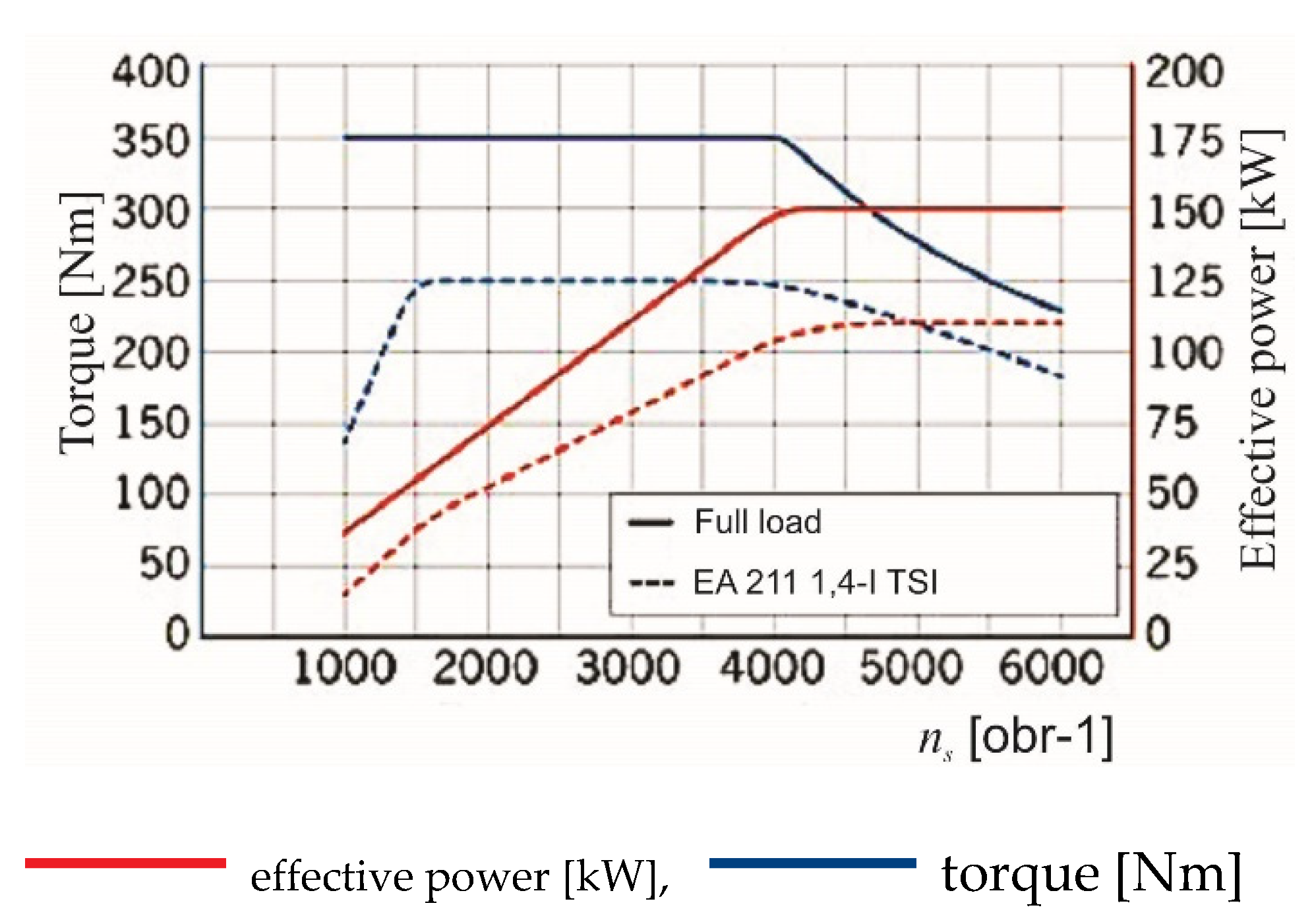
One of the main features indicating the area of application of a given type of engine for traction is its speed characteristics, where the main parameters presented there are useful power and torque. An example of a compilation of speed characteristics of an internal combustion engine and an electric engine is shown in
Figure 3.
When analyzing the list of characteristics presented in
Figure 3, it can be seen that the characteristics of the torque waveform of the electric motor constitute a significant fulfillment of the characteristics of the internal combustion engine. Specifically, in the range of low rotational speeds (n
s), the torque value for the combustion engine increases, and at the same time the electric motor generates the maximum value of the available torque. Such a system results in the improvement of the traction characteristics of vehicles equipped with a set of such engines, where the maximum value of the electric motor torque will allow for maximum acceleration values (especially from a stopped start). At the same time, the control system and the method of connecting the electric motor as an electric machine, inverter, and traction battery make it possible to recover electricity during braking, which can significantly improve the energy balance of the vehicle drive system.
Hence, it can be concluded that the combination of electric and internal combustion engines combines the advantages of both and obtains the possibly “optimal” traction characteristics of the powertrain system. An example of such a characteristic is shown in
Figure 4.
The analysis of the system of power and torque curves for the associated drive system (
Figure 4) reveals expansion of the rotational speed span for which the maximum value of the torque supplied by both engines was obtained. This is a recommendation to use this type of propulsion for urban and suburban travel, where mainly the torque parameter has decisive influence on the ability to accelerate while maintaining the lowest possible energy consumption and also reducing emissions.
Considering the conducted analysis, the undisputed advantage of using electric motors (electric machines) as an element or the main component of the energy conversion system in vehicles should be pointed out.
Today, various design and functional solutions are available for the construction of electric and hybrid powertrain systems. These include:
HEVs—hybrid electric vehicles—equipped with an internal combustion engine and electric engine system enabling different operating regimes of both engines, where the sub-types mild-HEV and full-HEV can be distinguished,
PHEVs—plug-in hybrid electric vehicles, equipped with an internal combustion engine and an electric engine, where the traction battery of the electric engine can be recharged from the power grid,
REXs—range extended electric vehicles, equipped with an electric motor and an auxiliary combustion engine designed to drive the generator to recharge the electric motor’s traction battery,
FCVs—fuel cell electric vehicles, where the main elements of the powertrain system are the electric motor, fuel cells, and traction battery,
BEVs—battery electric vehicles, where the main components of the powertrain system are the electric motor, traction battery, and inverter.
In each of the aforementioned cases, the role of the electric motor as a supporting or main source of mechanical energy can be indicated. Due to the field of torque supply, this source seems to be a better solution than the combustion engines used so far, especially combining this feature with zero emissions. A perceived disadvantage of electric vehicles [
9] is their relatively short range compared to conventional vehicles, and at the same time, a longer “refueling” time. The average ranges of electric vehicles usually range from about 100 to 600 km, depending on the type and brand of the vehicle. The lower values usually apply to hybrid vehicles (with electric drive).
Moreover, analyzing the available data on electric vehicles contained in the work of Depcik et al. [
10], a significant influence of the battery capacity (c) on the average road energy consumption expressed in kWh/100 km by cars equipped with electric drive type BEVs was noticed. This relationship was written in the form:
This relation allowed the authors to conclude that a change by every 100 kg of battery mass causes additional energy consumption at the level of 0.4 ÷ 1.3 kWh/100 km.
Considering the key selection criteria and concerns of vehicle users [
11], hydrogen powered systems may be one of the solutions for future vehicle powertrain systems.
4. Supply with Hydrogen
Hydrogen as a fuel can be effectively obtained as a product of water hydrolysis or as a reverse operation of a PEM fuel cell, where the energy necessary for the process can come from renewable sources [
12]. Currently, there is a significant increase [
9] in the interest of users and companies from the transport industry in this fuel applied to means of transport (road and rail vehicles). Hydrogen as a fuel and energy obtained from hydrogen to drive vehicles (power engines) was the subject of research as early as the late 1970s. Then, one of the precursors successfully introducing this fuel to power internal combustion engines was the company BMW, developing the model of the 7 series (E38) with a modified M73 engine powered by hydrogen in the form of gas. This engine burned the fuel in the cylinders in a “traditional” way, which resulted in the formation of water vapor and, unfortunately, nitrogen oxides. This latter component weakened the idea of an eco-friendly vehicle, and eventually the company ended the implementation of hydrogen in internal combustion engines with the E66 model.
Currently, hydrogen as a fuel is used to power fuel cells—chemical reactors in which, thanks to the chemical reaction of fuel (e.g., H
2) and oxygen, in the presence of catalytic layers, electrons are released, which results in electricity [
10]. Among the fuel cells, the following can be distinguished:
Alkaline fuel cells—AFC,
Polymer fuel cells with proton exchange membrane—PEMFC,
Acid fuel cells—PAFC,
Carbonate fuel cells—MCFC,
Oxide-ceramic fuel cells—SOFC,
Methanol fuel cells—DMFC.
Of the aforementioned, PEMFC cells have become the basic element of the construction of cells used for energy conversion in FCVs. A functional diagram of such a cell is shown in
Figure 5.
The cell principle of operation involves chemical reactions:
on the cathode;
which can be written:
In general, as a result of hydrogen oxidation at individual stages of the cell’s operation, electricity is obtained, which enables the supply of an electric motor or a battery. The amount of electricity obtained in a PEM fuel cell is directly proportional to the supplied mass of hydrogen and air, which means that the cell’s power control system works on a quantitative basis. PEM fuel cell electrodes are porous forms made of catalytic material (precious metals containing carbon—e.g., platinum covered with soot particles with a relatively large active surface) and a proton-conducting polymer. In addition, in the construction of the PEM cell, one can also notice bipolar plates, which are the cores supplying reacting gasses to the active surfaces and the electrical connection of the electrodes. They also allow the cells to be connected in stacks. The material used for the construction of the boards is plastic made of polymeric materials saturated with graphite or metal.
The engine power supply stacks can consist of up to 450 fuel cells, enabling voltage to be obtained in the range from 300 to 450 V, with the simultaneous energy density at the level of 1.5 ÷ 2.0 kW/dm3. A high precession fuel cell steering system based on physical properties of PEM is necessary to achieve high efficiency in energy conversion (from hydrogen to electric and later to mechanical energy).
5. Efficiency Analysis of Fuel Cells
The model for assessing the efficiency of car fuel cell operation was presented, inter alia, in the work of Gao J. et al. [
14]. The model analyzed there was based on the scheme of functioning of the automotive PEM cell system presented in
Figure 6.
This model considers the parameters of the flow of hydrogen and air as well as their thermodynamic state.
The analyzed model equations concerned:
As a result of the research, the cell characteristics were obtained, containing the relationship between the current value, the output power, and the efficiency of the cell system, as shown in
Figure 7.
By analyzing the course of the generalized curves (
Figure 7), it was shown that the PEM type fuel cell has two work areas in which the efficiency of energy conversion processes is significantly lower. At the same time, it was noticed that the electric power increases with the increase of the current intensity up to the saturation level (max) and then decreases. This characteristic is very similar to the speed characteristic of an internal combustion engine (
Figure 3b). Moreover, the maximum efficiency is in the “lower” region of optimal operation, which also resembles the relationship [
3] of the overall efficiency of a piston internal combustion engine to the torque curve and the position of the minimum unit fuel consumption.
On the basis of the above, it can be concluded that, in the case of FCVs, the “supply field” of current optimal for the operation of the fuel cell should be observed, and the electric load parameters and mechanical properties of the vehicle drive system should be selected from this range.
6. Resistance of Vehicle Motion and Controlling the Operation of Fuel Cells
As has already been shown, the performance characteristics of the fuel cell are variable in a fairly wide range. Therefore, it is necessary to parametrically control the quantities influencing the intensity and quality of the course of chemical reactions, because these in turn affect the amount of electric and thermal energy obtained in the conversion processes taking place in the cell. It is a process functionally similar to that taking place in the power control of conventional internal combustion engines, whereby controlling the ratio of the supplied fuel–air mixture (in a quantitative or qualitative manner) and the load conditions of this engine, the highest possible value of indicators describing the efficiency of the combustion engine operation is achieved with the lowest possible fuel consumption. Hence, in the case of electric vehicles, where the engine is powered by a fuel cell, the optimal values of the control parameters of the cell should also be sought in terms of its energy conversion efficiency and durability. The efficiency of the PEM fuel cell powered by hydrogen depends on many factors that allow for appropriate, momentary load conditions and intensity of the hydrogen oxidation reaction, resulting in the flow of current supplying the electric drive system. With regard to the traffic conditions, one should consider the balance of forces and powers decisive for the nature of the movement (uniform, variable), where, as in the case of conventional vehicles, the same base equations describe:
The driving force on the vehicle’s driving wheel,
Forces of resistance to motion (e.g., rolling, air, inertia, elevation).
Classically, the notation of the driving force (F_N) on the drive wheel is determined from the relationship:
where:
Mo—torque on the motor shaft,
ηm—mechanical efficiency of the drive train,
ic—total ratio of the drive train,
rd—dynamic radius of the drive wheel.
The value of the driving force written in the equation of vehicle motion is compared with the sum of the forces of resistance to motion, and such a relationship can be written as
where:
Q—vehicle weight resulting from the actual total vehicle weight,
f—coefficient of rolling resistance of wheels on the road surface,
α—road section elevation angle,
δ—coefficient of inertia of masses of rotating vehicle components,
cx—coefficient of air resistance for the vehicle body,
ρ—air density,
A—projected area of the vehicle front surface on a plane perpendicular to the road surface,
v—vehicle speed,
t—time.
The expression in parentheses describes the forces depending on the vehicle gravity (Q) and the phenomenon causing the drag force, whereas the last part of Equation (12) is related to the air resistance force. At the same time, it should be noted that in the case of equal values of the driving force and the sum of the resistance forces, a constant speed of the vehicle motion is obtained. In the case of a balance of forces other than zero, the vehicle speed value increases or decreases (acceleration or braking, respectively). The same applies to the power balance on the wheels with regard to the power of the resistance to motion. On the other hand, the balance of power available on the wheels of the driving axle and the power of resistance to motion is usually written in the form of a classic dependence, accounting for the speed of the vehicle’s movement and losses in the drive transmission system as:
where N
e is the effective (effective) power of the engine.
Hence, a vehicle powered by an electric motor powered by a fuel cell should enable the adjustment of the electric power of the fuel cell to supply the vehicle’s propulsion engine in a way that accounts for the momentary conditions of the vehicle’s motion, and the relations between the quantities present are not linear. At the same time, considering the structure and operating characteristics of PEM fuel cells and the dependencies describing the conditions of vehicle movement, it can be seen that, in addition to the already noted balance adjustment of the amount of energy supplied to the electric motor of the vehicle, the amount obtained in the fuel cell may be a balancing of the supply or demand for power through the battery system traction. To obtain the highest possible values of efficiency indicators for the drive system of a PEM cell vehicle, it should be noted that this balancing should, however, be an element of an auxiliary correction in the event of imperfection of the fuel cell power control system or resulting from system features (e.g., in the “cold start” phase). It is directly related to the consumption of hydrogen as fuel and the efficiency of energy conversion processes in the vehicle’s propulsion system.
Work [
16] presents the results of the research on the control system of the work efficiency (power) of a fuel cell in relation to energy conversion processes. In the analyzed case of the PEM fuel cell, reference was made to the strategy of keeping the ratio as constant as possible between the mass of the factors involved in the reaction (oxygen and hydrogen) and referring to the control system of the actuators of the fuel cell control system in the form of valves, injector, and compressor. As referred to in the source [
17], the value of the relation defined as the oxygen excess coefficient should be 2. The value of this coefficient (λ
O2) was defined as the relationship between the mass of oxygen flowing into the cell (m
O2in) and the mass of oxygen required for the oxidation reaction of the incoming mass of hydrogen (m
o2react) and is described by the equation in the form:
The research [
16,
18] determined that the actuator having a direct impact on the values of the excess oxygen coefficient as well as the electric power of the cell is the rotational speed of the compressor rotor, and at the same time this speed will be a regulated parameter. These tests were carried out using the MATLAB/Simulink environment. The aim of the research was to show how the voltage control of the compressor rotor speed will affect the actual supply of air (oxygen) to the fuel cell by changing its power and whether this control allows for dynamically and precisely adjusting the cell’s power to its instantaneous load. The result of the research was obtaining the characteristics on the basis of which information was obtained that the modified control method called Fast Terminal Integral Sliding Mode Control (FTISMC) allows for effectively adjusting the power of the fuel cell to its instantaneous load, even in the event of sudden changes in the current intensity. This also allows us to conclude that the method of control proposed by the researchers made it possible to efficiently adjust the power of the FCEV car propulsion system to the momentary traffic conditions.
7. Construction Specifications of Hydrogen Vehicles
Many practical experiments show that the main trouble of hydrogen power train systems is connected with the hydrogen storage on board the vehicle. Currently, vehicles equipped with PEM fuel cells powered by hydrogen are built similarly to hybrid vehicles, with the difference that instead of an internal combustion engine, a set of fuel cells (stack) is installed and there is a hydrogen supply system with a tank.
Hydrogen, as a fuel, is an obstacle in the storage process due to its physico-chemical properties and is usually stored on board a vehicle in the form of:
Gas under very high pressure (up to 70 MPa) in steel cylinders made of Al alloys or composite,
Liquid at a pressure close to atmospheric pressure and a temperature of −253 °C in cryogenic tanks,
Chemically bound (metal hydrides Fe, Ti, Mg, Mn, Ni) in tanks that are also heat exchangers,
Glass microgranules and carbon nanotubes.
An example of a tank designed for storing hydrogen in the compressed phase is shown in
Figure 8.
A typical functional structure of a vehicle hydrogen supply system with the use of PEM fuel cells is shown in
Figure 9.
When analyzing the structure of a typical power supply system (
Figure 9), it can be seen that the PEM cell is a source of electricity for the traction motor, and at the same time, in road situations requiring increased energy demand, the vehicle engine is also powered by a traction battery of much smaller capacity than in the case of electric vehicles.
On the other hand, the traction battery is charged as the vehicle slows down due to energy obtained from the fuel cell. The processes of energy flow between these key elements of the system are controlled by an electronic device. Hence, both the already noted structural system and the basic operational strategy of the FCVs are almost identical to hybrid vehicles [
20].
The set of the main driving elements of the BMW car is shown in
Figure 10.
Solutions structurally similar to FCVs are used for the installation of fuel cells in commercial vehicles, buses, and other means of transport.
8. Summary
The powertrain systems of current vehicles are constantly modernized, which is also reflected in the development of fuel cell systems. Choosing hydrogen as the lead fuel appears to be the right way to achieve the key goals of zero emissions and the real range of an FCV vehicle comparable to a conventional vehicle. An obstacle to the development of such power systems is the system of production and distribution of hydrogen. The problem at the stage of implementing solutions of this type may be the human factor due to the relatively high technical standards, e.g., in hydrogen bunkering. Also due to the fact that hydrogen does not exist in the free state, and its production is energy-consuming, it should be obtained in technical processes with the use of energy from renewable sources. Then, there would be a real opportunity to meet the criteria that are key to achieving a zero carbon footprint in vehicle use.
Limitations
This article is a review article and due to the limitation of access to reliable and complete data from car manufacturers and other researchers, as well as the too short time of operation of the discussed solutions, the results of quantitative and qualitative analysis may, in the authors’ opinion, be too imprecise and should not be used or generalized, as they could be too subjective and mislead the reader.


