
Grid Connection Circuits for Powerful Regenerative Electric Drives of Rolling Mills: Review

Abstract
:1. Introduction
2. Power Circuits of the Main Electric Drives of Rolling Mills

| Figure Number | AFE Drive Power SAFE, kVAR | Transformer Power St, kVAR | Connection | 1st/2nd Transformer Voltage, kV | PPWM Average Frequency |
|---|---|---|---|---|---|
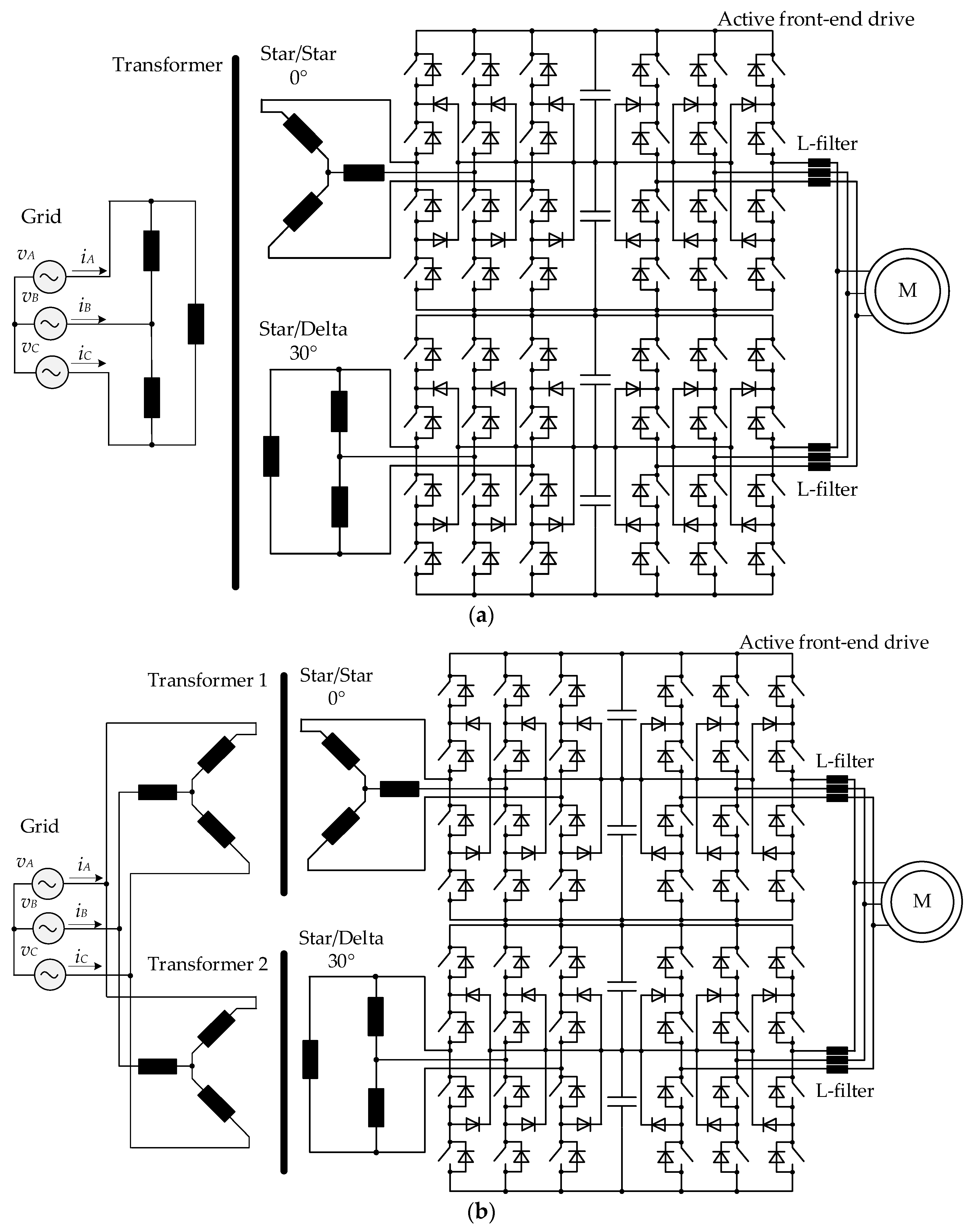
| Figure 3a | 12,000 | 12,000 | star/star | 10/3.3 | 250–350 |
| Figure 3b | 14,000 | 14,000 | delta/delta | ||
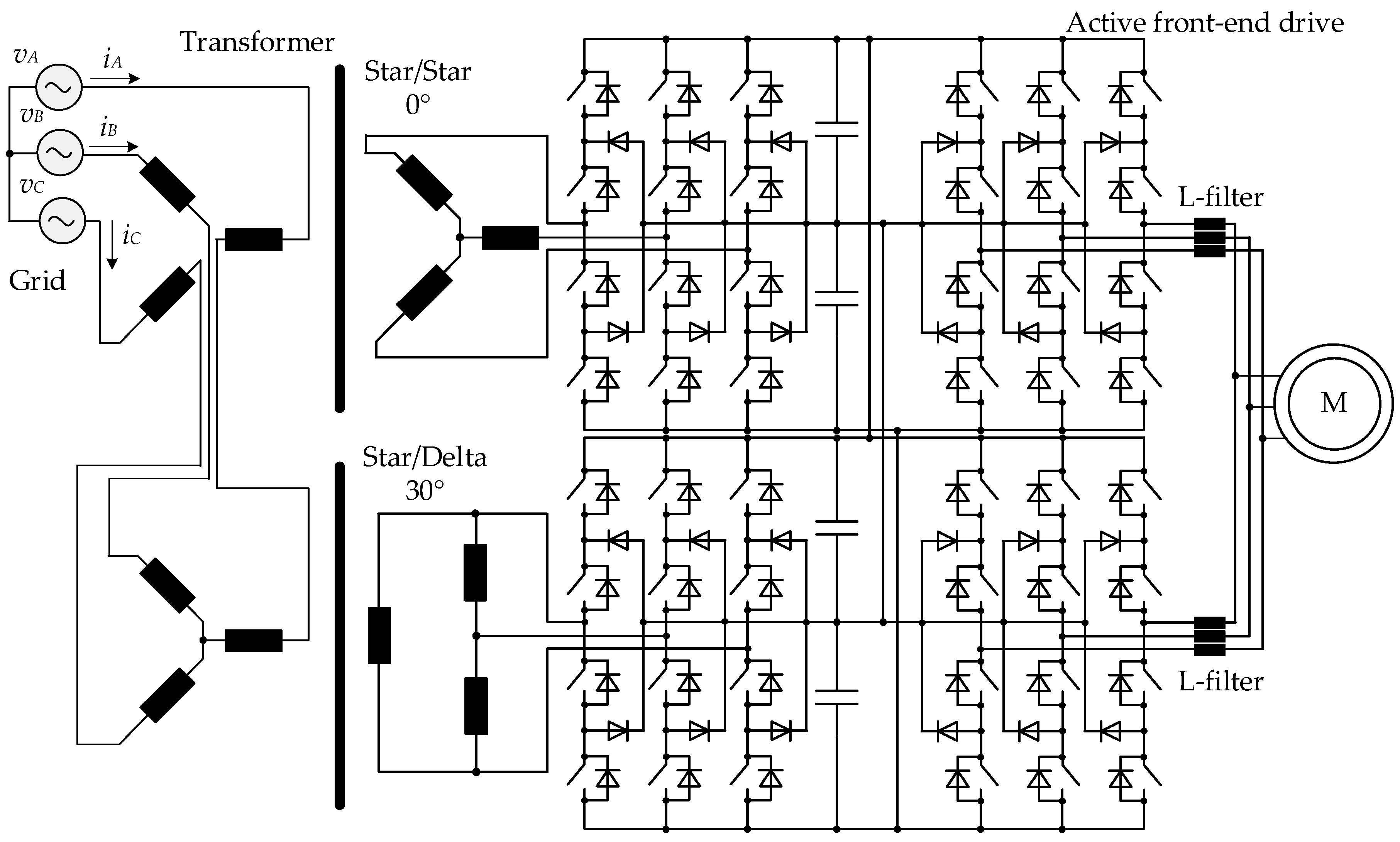
| Figure 4 and Figure 5 | 12,000 | 12,000 | star/delta-star | ||
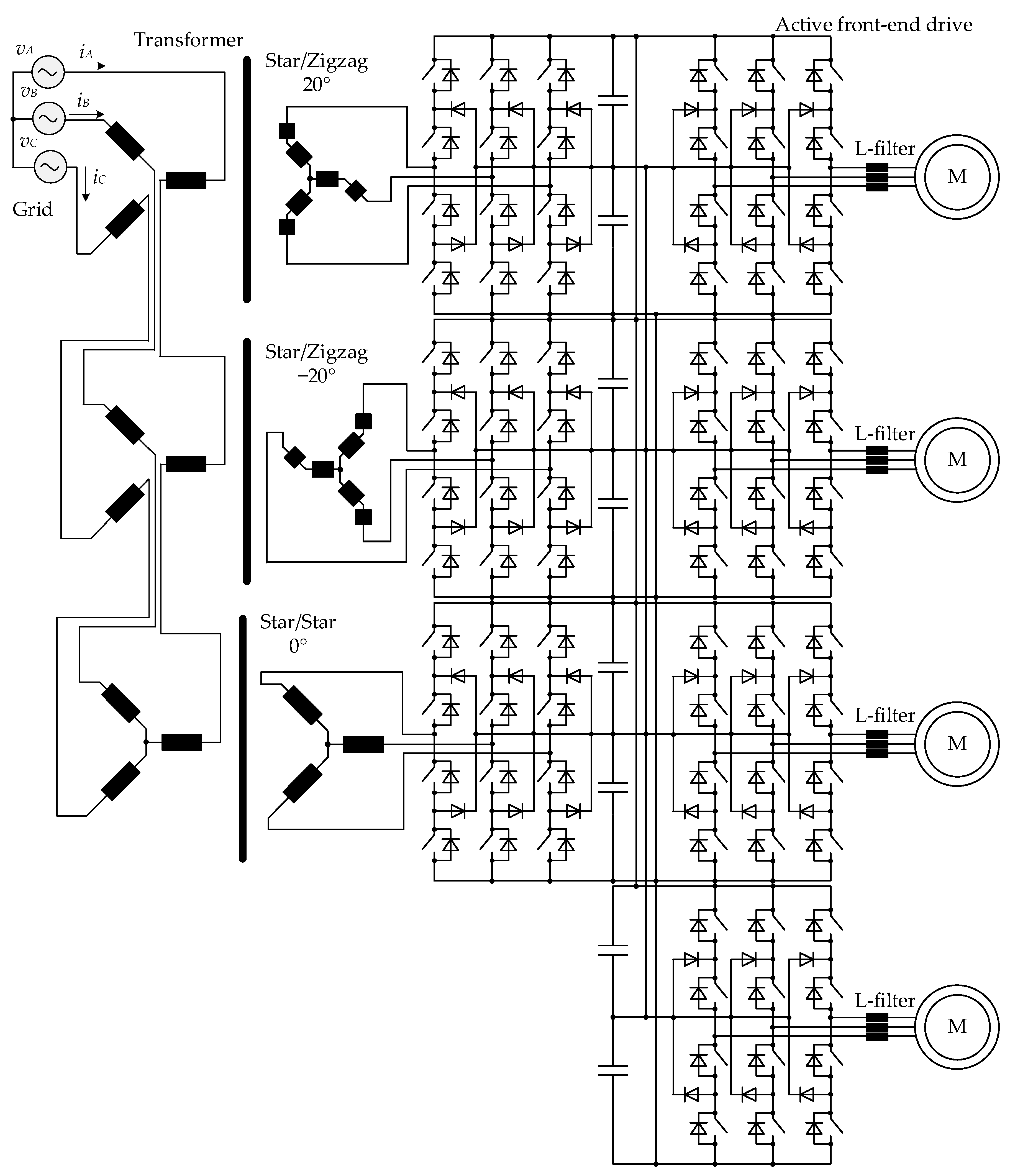
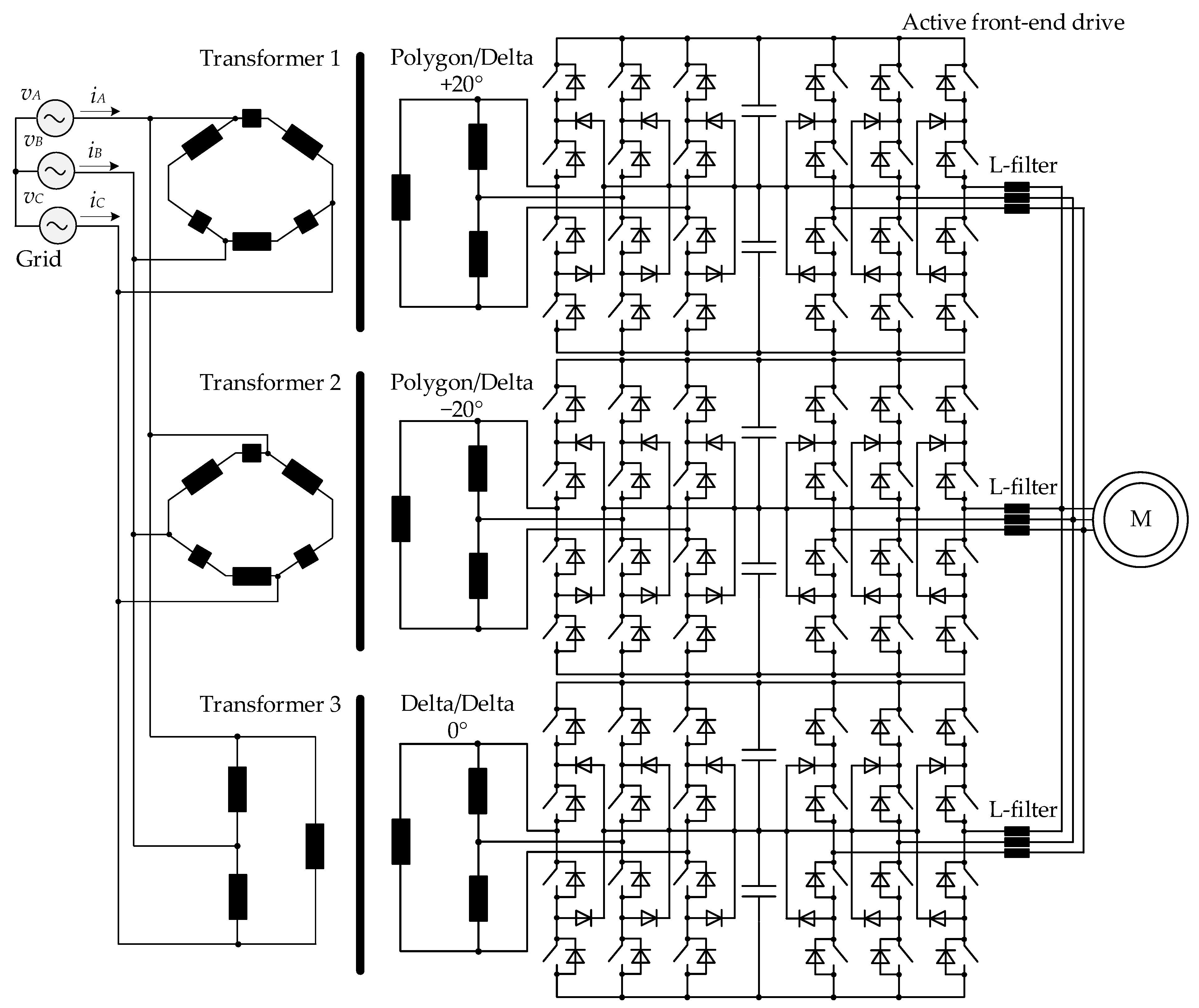
| Figure 6 | 18,000 | 20,000 | delta/delta; delta/double polygon | ||
| Figure 7 | 18,000 | 18,000 | star/delta-double zigzag |
3. PPWM with SHE
4. Simulation Results
- (1)
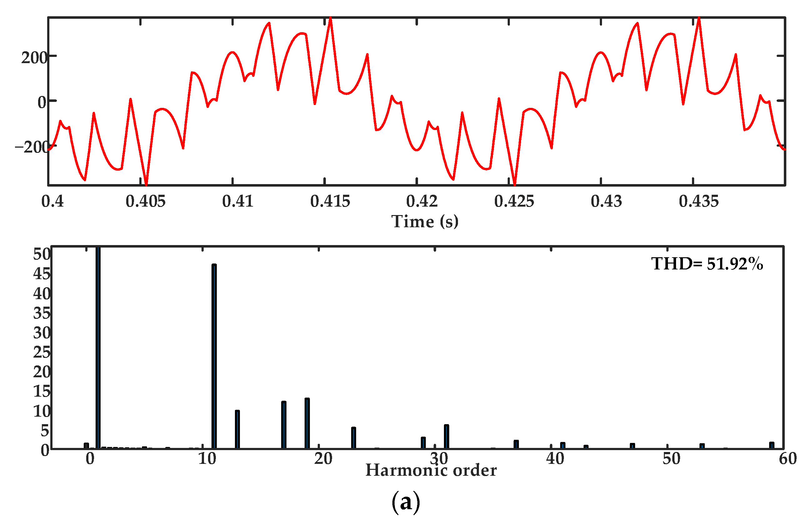
- As expected, the six-pulse circuit showed the worst grid current THD of 51.92% at the lowest PPWM with SHE frequency of 150 Hz with the elimination of two significant fifth and seventh harmonics (Figure 9a). Increasing the frequency to 250 Hz (Figure 9b) and then 350 Hz (Figure 9c) allowed significantly reducing the grid current THD; however, the results were several times worse than with 12- and 18-pulse circuits. The transformer’s secondary winding current simulation results are not provided for a six-pulse connection circuit since the transient process nature is the same as that shown in Figure 9.
- (2)
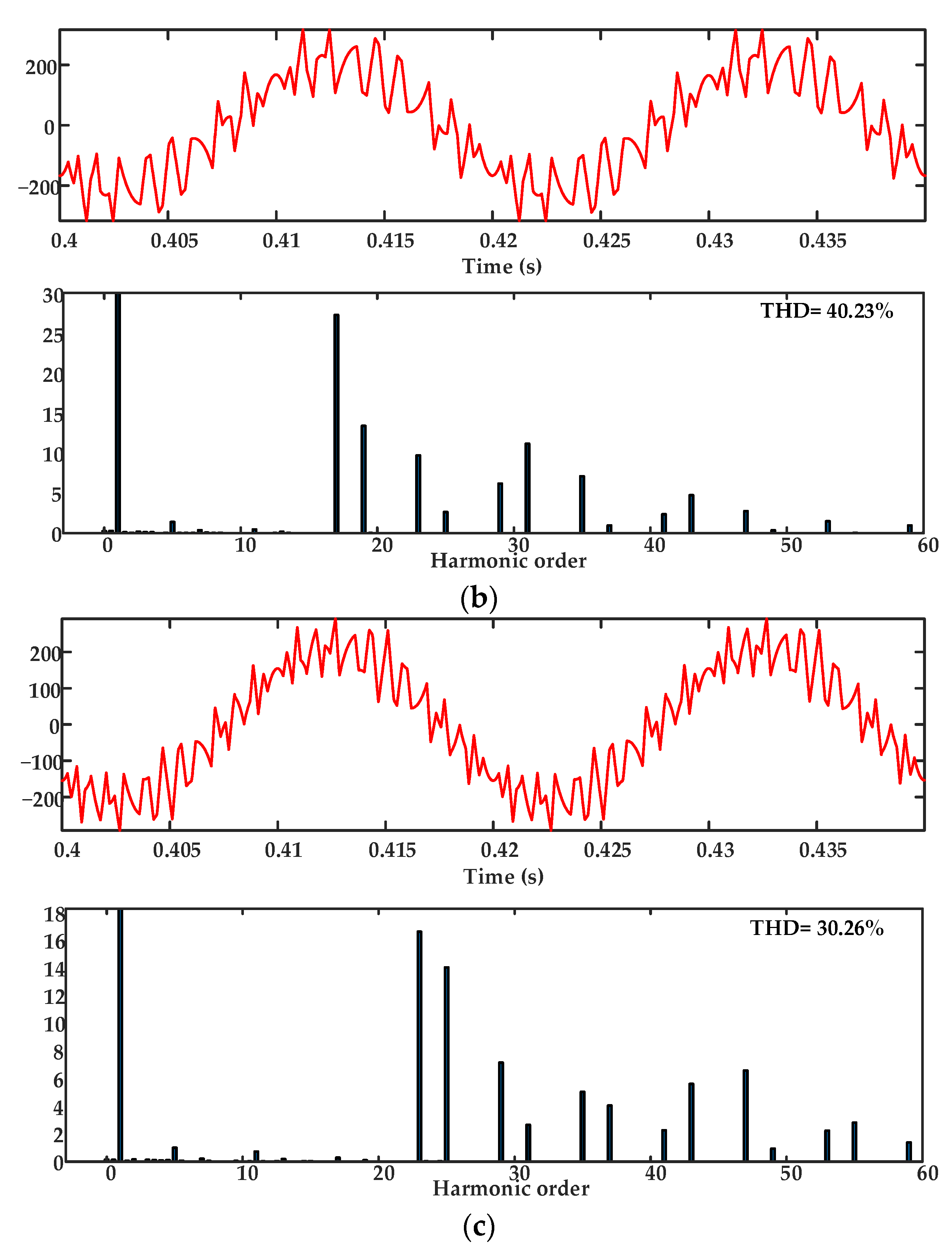
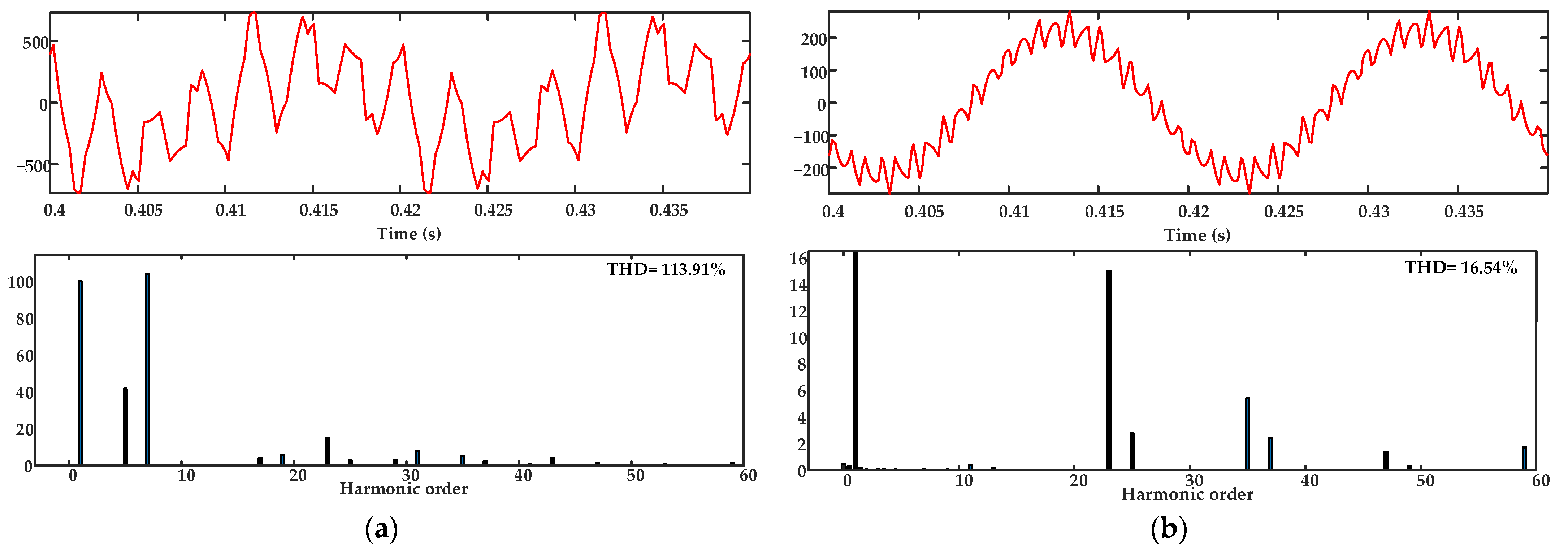
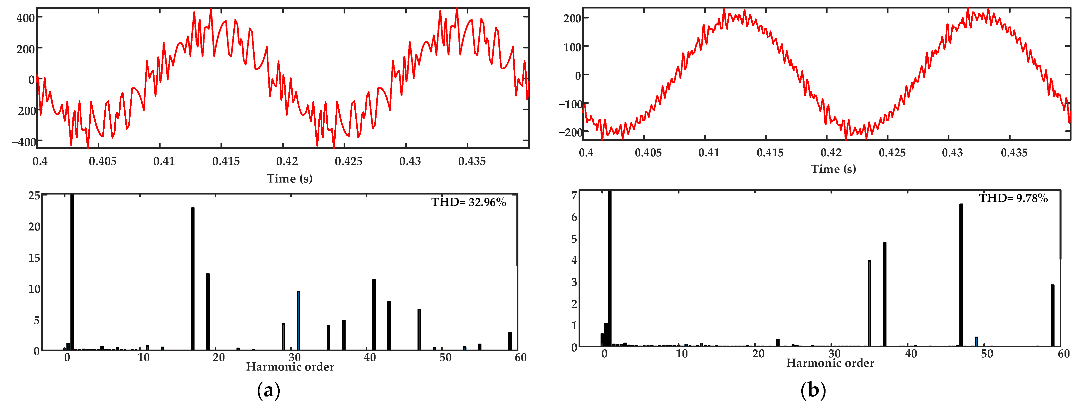
- At the PPWM with SHE frequency of 150 Hz with two significant 11th and 13th harmonics eliminated (Figure 10a), a 12-pulse circuit demonstrates a significantly better grid current THD (16.54%) than a 6-pulse one. However, the transformer’s secondary winding current THD (Figure 10b) is 113.91%, which is approximately twice as high as with the six-pulse circuit. Note that with an increase in the PPWM with SHE frequency by 100 Hz with additionally eliminated fifth and seventh harmonics, the grid current and the transformer’s secondary winding current THDs decreased sharply by 15% and 4 times, amounting to 12.44% (Figure 11a) and 34.18% (Figure 11b), respectively. Increasing the PPWM with SHE frequency up to 350 Hz with the 5th, 7th, 11th, 13th, 23rd, and 25th harmonics eliminated (Figure 12a) expectedly provides the most favorable grid current THD in a 12-pulse circuit; however, the transformer’s secondary winding current THD has not changed noticeably (Figure 12b).
- (3)
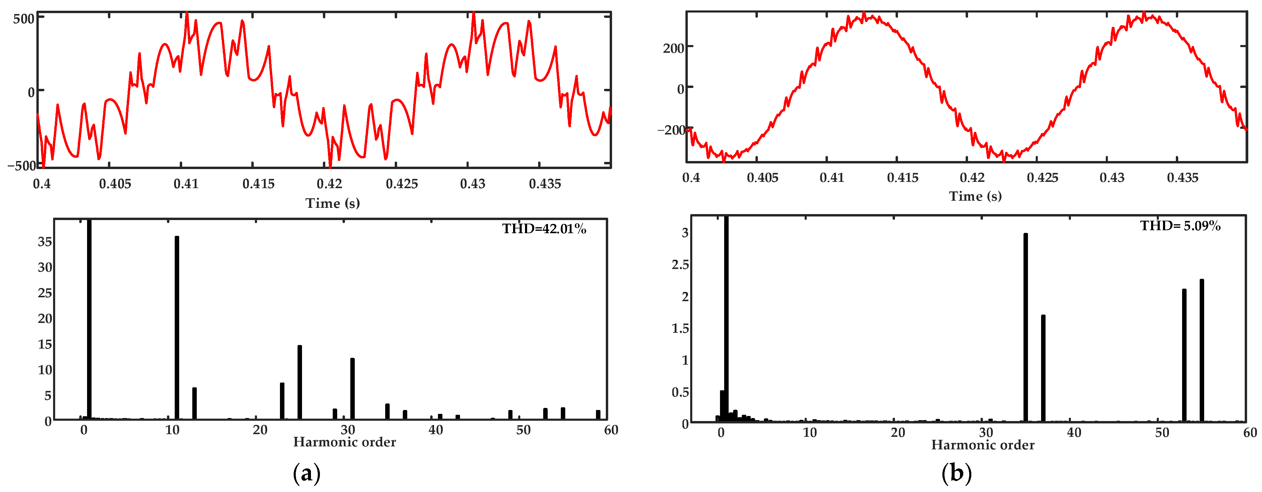
- At the PPWM with SHE frequency of 150 Hz with two significant 17th and 19th harmonics eliminated, the 18-pulse circuit, similarly, demonstrates a poor transformer’s secondary winding current THD of 118.17% (Figure 13a). However, the grid current THD is only 6.57% (Figure 13b), which is a very good result for a frequency of 150 Hz. With an increase in the PPWM with SHE frequency by 100 Hz with additionally eliminated fifth and seventh harmonics, we can see that the transformer’s secondary winding current and the grid current THDs decrease sharply by three times and 15% to 42.01% (Figure 14a) and 5.09% (Figure 14b), respectively. Increasing the PPWM with SHE frequency up to 350 Hz with the 5th, 7th, 17th, 19th, 35th, and 37th harmonics eliminated results in the grid current THD of 4.26% (Figure 15a), which, as expected, is the best result obtained.
- (4)
- The 18-pulse circuit, other things being equal, allows reducing the grid current THD by two and five-to-seven times compared to the 12-pulse and 6-pulse circuits, respectively.
- (5)
- Eliminating the fifth and seventh harmonics not only improves the transformer’s secondary winding current THD in the 12- and 18-pulse connection circuits but also affects positively the grid current quality.
5. Experimental Results
6. Conclusions
- (1)
- The paper reviews the most commonly used grid connection circuits for the main AC REDs of rolling mills. Their advantages and drawbacks, basic components and their characteristics, and three-level AFE’s PPWM with SHE algorithms are provided. It is shown that the converters topologies and the PPWM with SHE algorithms should be considered when building the considered power circuits,
- (2)
- Simulation was performed under the same conditions to objectively estimate and compare the spectra and current THDs of the three-level AFE’s 6-, 12-, and 18-pulse connection circuits with various PPWM with SHE algorithms, which was not carried out in previously published studies,
- (3)
- The comparison results are shown for the powerful AC RED 6-, 12-, and 18-pulse connection circuits with various three-level AFE’s PPWM with SHE algorithms. The results can be used to choose the optimal connection circuit and algorithm,
- (4)
- The experimental data confirm the observations and conclusions provided in this review,
- (5)
- Based on a literature review, simulation results, and experimental data, recommendations are suggested for choosing PPWM with SHE algorithms for three-level AFEs as part of multi-pulse connection circuits. The results described are of high genericity and can be used by researchers and engineers for designing or performing similar studies in other circuits to provide the electromagnetic compatibility of non-linear consumers.
Author Contributions
Funding
Institutional Review Board Statement
Informed Consent Statement
Data Availability Statement
Conflicts of Interest
References
- Kouro, S.; Malinowski, M.; Gopakumar, K.; Pou, J.; Franquelo, L.G.; Wu, B.; Rodriguez, J.; Pérez, M.A.; Leon, J.I. Recent Advances and Industrial Applications of Multilevel Converters. Ind. Electron. IEEE Trans. 2010, 57, 2553–2580. [Google Scholar] [CrossRef]
- Abu-Rub, H.; Bayhan, S.; Moinoddin, S.; Malinowski, M.; Guzinski, J. Medium-Voltage Drives: Challenges and existing technology. IEEE Power Electron. Mag. 2016, 3, 29–41. [Google Scholar] [CrossRef]
- Rajesh, D.; Ravikumar, D.; Bharadwaj, S.K.; Vastav, B.K.S. Design and control of digital DC drives in steel rolling mills. In Proceedings of the 2016 International Conference on Inventive Computation Technologies (ICICT), Coimbature, India, 26–27 August 2016. [Google Scholar] [CrossRef]
- Abu-Rub, H.; Lewicki, A.; Iqbal, A.; Guzinski, J. Medium Voltage Drives-Challenges and Requirements. In Proceedings of the IEEE International Symposium on Industrial Electronics, Bari, Italy, 4–7 July 2016. [Google Scholar] [CrossRef]
- IEEE Std. 519-1992; IEEE Recommended Practices and Requirements for Harmonic Control in Electrical Power Systems. IEEE: New York, NY, USA, 1993.
- IEEE Std. 1531; IEEE Guide for Application and Specification of Harmonic Filters. IEEE: New York, NY, USA, 2003.
- EN 50160; Voltage Characteristics of Electricity Supplied by Public Distribution Systems. Wroclaw University of Technology: Wroclaw, Poland, 2001.
- IEC 61000-3-2:2019; Electromagnetic Compatibility (EMC)—Part 3-2: Limits—Limits for Harmonic Current Emissions (Equipment input Current ≤16 A per phase). IEC: Geneva, Switzerland, 2019.
- Kouro, S.; Rodriguez, J.; Wu, B.; Bernet, S.; Perez, M. Powering the Future of Industry: High-Power Adjustable Speed Drive Topologies. IEEE Ind. Appl. Mag. 2012, 18, 26–39. [Google Scholar] [CrossRef]
- Jing, T.; Maklakov, A.S. A Review of Voltage Source Converters for Energy Applications. In Proceedings of the International Ural Conference on Green Energy, Chelyabinsk, Russia, 4–6 October 2018. [Google Scholar] [CrossRef]
- Song-Manguelle, J.; Thurnherr, T.; Schroder, S.; Rufer, A.; Nyobe-Yome, J.-M. Re-generative asymmetrical multi-level converter for multi-megawatt variable speed drives. In Proceedings of the 2010 IEEE Energy Conversion Congress and Exposition, Atlanta, GA, USA, 12–16 September 2010. [Google Scholar] [CrossRef]
- Rodriguez, J.; Franquelo, L.G.; Kouro, S.; Leon, J.I.; Portillo, R.C.; Prats, M.A.M.; Perez, M.A. Multilevel converters: An enabling technology for high-power applications. Proc. IEEE 2009, 97, 1786–1817. [Google Scholar] [CrossRef] [Green Version]
- Wang, L. Modeling and Control of Sustainable Power Systems: Towards Smarter and Greener Electric Grids, 1st ed.; Springer: Hoboken, NJ, USA, 2012. [Google Scholar]
- Kornilov, G.P.; Nikolaev, A.A.; Khramshin, T.R. Mathematical Modeling of the Metallurgical Plants’ Electrotechnical Complexes; Nosov Magnitogorck State Technical University: Magnitogorsk, Russia, 2012. [Google Scholar]
- Mittal, N.; Singh, B.; Singh, S.P.; Dixit, R.; Kumar, D. Multilevel Inverters: A Literature Survey on Topologies and Control Strategies. In Proceedings of the 2nd International Conference on Power, Control and Embedded Systems, Allahabad, India, 1–11 December 2012. [Google Scholar] [CrossRef]
- Rodriguez, J.; Bernet, S.; Wu, B.; Pontt, J.O.; Kouro, S. Multilevel voltage-source-converter for industrial medium-voltage drives. IEEE Trans. Ind. Electron. 2007, 54, 2930–2945. [Google Scholar] [CrossRef]
- Franquelo, L.G.; Rodriguez, J.; Leon, J.I.; Kouro, S.; Portillo, R.; Prats, M.A.M. The age of multilevel converters arrives. IEEE Ind. Electron. Mag. 2008, 2, 28–39. [Google Scholar] [CrossRef] [Green Version]
- Ge, B.; Peng, F.Z.; Wu, B.; de Almeida, A.T.; Abu-Rub, H. An effective control technique for medium-voltage high-power induction motor fed by cascaded neutral-point-clamped inverter. IEEE Trans. Ind. Electron. 2010, 57, 2659–2668. [Google Scholar] [CrossRef]
- Ewanchuk, J.; Salmon, J.; Vafakhah, B. A five-/nine-level twelve-switch neutral-point-clamped inverter for high-speed electric drives. IEEE Trans. Ind. Electron. 2011, 47, 2145–2153. [Google Scholar] [CrossRef]
- Bernet, S. State of the art and developments of medium voltage converters—An overview. Prz. Elektrotechniczny 2006, 82, 1–10. [Google Scholar]
- Mohammed, S.A.; Abdel-Moamen, M.A.; Hasanin, B. A review of the state-of-the-art of power electronics for power system applications. Int. J. Electron. Commun. Eng. Res. 2013, 1, 43–52. [Google Scholar]
- Fazel, S.S. Investigation and Comparison of Multi-Level Converters for Medium Voltage Applications; Eng.D.-Technische Universität Berlin: Berlin, Germany, 2007. [Google Scholar]
- Nabae, A.; Takahashi, I.; Akagi, H. New neutral-point-clamped PWM inverter. IEEE Trans. Ind. Appl. 1981, IA–17, 518–523. [Google Scholar] [CrossRef]
- Leon, J.I.; Vazquez, S.; Franquelo, L.G. Multilevel converters: Control and modulation techniques for their operation and industrial applications. Proc. IEEE 2017, 105, 2066–2081. [Google Scholar] [CrossRef]
- Abu-Rub, H.; Holtz, J.; Rodriguez, J.; Ge, B. Medium-voltage multilevel converters—State of the art, challenges, and requirements in industrial applications. IEEE Trans. Ind. Electron. 2010, 57, 2581–2596. [Google Scholar] [CrossRef]
- Wu, B.; Narimani, M. High-Power Converters and AC Drives, 2nd ed.; Wiley & Sons: Hoboken, NJ, USA, 2017. [Google Scholar]
- Singh, B.; Gairola, S.; Singh, B.N.; Chandra, A.; Al-Haddad, K. Multipulse AC–DC Converters for Improving Power Quality: A Review. IEEE Trans. Power Electron. 2008, 23, 260–281. [Google Scholar] [CrossRef]
- Chen, J.; Shen, Y.; Chen, J.; Bai, H.; Gong, C.; Wang, F. Evaluation on the Autoconfigured Multipulse AC/DC Rectifiers and Their Application in More Electric Aircrafts. IEEE Trans. Transp. Electrif. 2020, 6, 1721–1739. [Google Scholar] [CrossRef]
- Nikolaev, A.A.; Bulanov, M.V.; Shakhbieva, K.A. Quality Improvement of Electric Power in the Intra-factory Electric Networks through the Use of PWM Algorithm Selective Harmonic Mitigation. In Proceedings of the 2020 Russian Workshop on Power Engineering and Automation of Metallurgy Industry: Research & Practice (PEAMI), Magnitogorsk, Russia, 25–26 September 2020. [Google Scholar] [CrossRef]
- Okayama, H.; Uchida, R.; Koyama, M.; Mizoguchi, S.; Tamai, S.; Ogawa, H.; Fujii, T.; Shimomura, Y. Large capacity high performance 3-level GTO inverter system for steel main rolling mill drives. In Proceedings of the IAS ’96. Conference Record of the 1996 IEEE Industry Applications Conference Thirty-First IAS Annual Meeting, San Diego, CA, USA, 6–10 October 1996. [Google Scholar] [CrossRef]
- De Nazareth Ferreira, V.; Cupertino, A.F.; Pereira, H.A.; Rocha, A.V.; Isaac Seleme, S.; de Jesus Cardoso Filho, B. Design of high-reliable converters for medium-voltage rolling mills systems. In Proceedings of the 2017 IEEE Industry Applications Society Annual Meeting, Cincinnati, OH, USA, 1–5 October 2017. [Google Scholar] [CrossRef]
- Bocker, J.; Janning, J.; Jebenstreit, H. High dynamic control of a three-level voltage-source-converter drive for a main strip mill. IEEE Trans. Ind. Electron. 2002, 49, 1081–1092. [Google Scholar] [CrossRef]
- Safaeian, M.; Jalilvand, A.; Taheri, A. A MRAS Based Model Predictive Control for Multi-Leg Based Multi-Drive System Used in Hot Rolling Mill Applications. IEEE Access 2020, 8, 215493–215504. [Google Scholar] [CrossRef]
- Radionov, A.A.; Maklakov, A.S.; Gasiyarov, V.R. Smart Grid for main electric drive of plate mill rolling stand. In Proceedings of the 2014 International Conference on Mechanical Engineering, Automation and Control Systems (MEACS), Tomsk, Russia, 16–18 October 2014. [Google Scholar] [CrossRef]
- Pontt, J.A.; Rodriguez, J.R.; Liendo, A.; Newman, P.; Holtz, J.; San Martin, J.M. Network-Friendly Low-Switching-Frequency Multipulse High-Power Three-Level PWM Rectifier. IEEE Trans. Ind. Electron. 2009, 56, 1254–1262. [Google Scholar] [CrossRef]
- Maklakov, A.S.; Radionov, A.A. Integration prospects of electric drives based on back to back converters in industrial smart grid. In Proceedings of the 2014 12th International Conference on Actual Problems of Electronics Instrument Engineering (APEIE), Novosibirsk, Russia, 2–4 October 2014. [Google Scholar] [CrossRef]
- Zhang, Y.; Tan, J.; Wang, J.; Li, J. Hardware-in-loop simulation and application for high-power AC-DC-AC rolling mill driving system. In Proceedings of the 2015 IEEE 11th International Conference on Power Electronics and Drive Systems, Sydney, NSW, Australia, 9–12 June 2015. [Google Scholar] [CrossRef]
- Nakajima, T.; Suzuki, H.; Izumi, K.; Sugimoto, S.; Yonezawa, H.; Tsubota, Y. A converter transformer with series-connected line-side windings for a DC link using voltage source converters. In Proceedings of the IEEE Power Engineering Society. 1999 Winter Meeting, New York, NY, USA, 31 January–4 February 1999; Volume 2, pp. 1073–1078. [Google Scholar] [CrossRef]
- Kornilov, G.P.; Khramshin, T.R.; Abdulveleev, I.R. Increasing stability of electric drives of rolling mills with active front ends at voltage sag. In Proceedings of the 2019 International Conference on Electrotechnical Complexes and Systems (ICOECS), Ufa, Russia, 21–25 October 2019. [Google Scholar] [CrossRef]
- Ferreira, V.N.; Cupertino, A.F.; Pereira, H.A.; Rocha, A.V.; Seleme, S.I.; Cardoso, B. Design and Selection of High Reliability Converters for Mission Critical Industrial Applications: A Rolling Mill Case Study. IEEE Trans. Ind. Appl. 2018, 54, 4938–4947. [Google Scholar] [CrossRef]
- Alonso Orcajo, G.; Rodriguez, D.J.; Cano, J.M.; Norniella, J.G.; Ardura, G.P.; Llera, T.R.; Cifrian, R.D. Retrofit of a Hot Rolling Mill Plant with Three-Level Active Front End Drives. IEEE Trans. Ind. Appl. 2018, 54, 2964–2974. [Google Scholar] [CrossRef]
- Espinosa, E.E.; Melin, P.E.; Garcés, H.O.; Baier, C.R.; Espinoza, J.R. Multicell AFE Rectifier Managed by Finite Control Set–Model Predictive Control. IEEE Access 2021, 9, 137782–137792. [Google Scholar] [CrossRef]
- Chengsheng, W.; Chongjian, L.; Chunyi, Z.; Zhiming, L.; Qiongtao, Y.; Wei, D.; Fan, L. Study on large power converter system for rolling mills. In Proceedings of the 2012 15th International Power Electronics and Motion Control Conference (EPE/PEMC), Novi Sad, Serbia, 4–6 September 2012. [Google Scholar] [CrossRef]
- Maklakov, A.S.; Jing, T.; Radionov, A.A.; Gasiyarov, V.R.; Lisovskaya, T.A. Finding the Best Programmable PWM Pattern for Three-Level Active Front-Ends at 18-Pulse Connection. Machines 2021, 9, 127. [Google Scholar] [CrossRef]
- Gasiyarov, V.R.; Maklakov, A.S.; Lisovski, R.A. Grid power control by medium voltage AC drives based on back-to-back converters. In Proceedings of the 2018 IEEE Conference of Russian Young Researchers in Electrical and Electronic Engineering (EIConRus), Moscow and St. Petersburg, Russia, 29 January–1 February 2018. [Google Scholar] [CrossRef]
- Wang, P.; Liu, F.; Zha, X.; Gong, J.; Zhu, F.; Xiong, X. A Regenerative Hexagonal-Cascaded Multilevel Converter for Two-Motor Asynchronous Drive. IEEE J. Emerg. Sel. Top. Power Electron. 2017, 5, 1687–1699. [Google Scholar] [CrossRef]
- Edpuganti, A.; Rathore, A.K. A Survey of Low Switching Frequency Modulation Techniques for Medium-Voltage Multilevel Converters. IEEE Trans. Ind. Appl. 2015, 51, 4212–4228. [Google Scholar] [CrossRef]
- Jing, T.; Maklakov, A.; Radionov, A.; Baskov, S.; Kulmukhametova, A. Research on hybrid SHEPWM based on different switching patterns. Int. J. Power Electron. Drive Syst. 2019, 10, 1875–1884. [Google Scholar] [CrossRef]
- Edpuganti, A.; Rathore, A.K. A survey of low-switching frequency modulation techniques for medium-voltage multilevel converters. In Proceedings of the 2014 IEEE Industry Application Society Annual Meeting, Vancouver, BC, Canada, 5–9 October 2014. [Google Scholar] [CrossRef]
- Veillon, M.; Espinosa, E.; Garcés, H.; Melín, P.; Reyes, M.; Baier, C.; Mirzaeva, G. Feedback Quantizer and Non Linear Control Applied to Multi-Cell AFE Rectifier. In Proceedings of the 2021 IEEE CHILEAN Conference on Electrical, Electronics Engineering, Information and Communication Technologies (CHILECON), Valparaíso, Chile, 6–9 December 2021. [Google Scholar] [CrossRef]
- Fernandez-Rebolleda, H.; Sanchez-Ruiz, A.; Ceballos, S.; Perez-Basante, A.; Valera-Garcia, J.J.; Konstantinou, G.; Pou, J. Analysis and Optimization of Modulation Transitions in Medium-Voltage High-Power Converters. IEEE Trans. Power Electron. 2021, 36, 9984–9993. [Google Scholar] [CrossRef]
- Cheng, J.; Xu, T.; Chen, D.; Chen, G. Dynamic and Steady State Response Analysis of Selective Harmonic Elimination in High Power Inverters. IEEE Access 2021, 9, 75588–75598. [Google Scholar] [CrossRef]
- Birth, A.; Geyer, T.; Mouton, H.d.T.; Dorfling, M. Generalized Three-Level Optimal Pulse Patterns with Lower Harmonic Distortion. IEEE Trans. Power Electron. 2020, 35, 5741–5752. [Google Scholar] [CrossRef]
- Jing, T.; Maklakov, A.S.; Radionov, A.A.; Gasiyarov, V.R. Research of a flexible space-vector-based hybrid PWM transition algorithm between SHEPWM and SHMPWM for three-level NPC inverters. Machines 2020, 8, 57. [Google Scholar] [CrossRef]
- Marquez Alcaide, A.; Leon, J.I.; Laguna, M.; Gonzalez-Rodriguez, F.; Portillo, R.; Zafra-Ratia, E.; Vazquez, S.; Franquelo, L.G.; Bayhan, S.; Abu-Rub, H. Real-Time Selective Harmonic Mitigation Technique for Power Converters Based on the Exchange Market Algorithm. Energies 2020, 13, 1659. [Google Scholar] [CrossRef] [Green Version]
- Al-Hitmi, M.; Ahmad, S.; Iqbal, A.; Padmanaban, S.; Ashraf, I. Selective Harmonic Elimination in a Wide Modulation Range Using Modified Newton–Raphson and Pattern Generation Methods for a Multilevel Inverter. Energies 2018, 11, 458. [Google Scholar] [CrossRef] [Green Version]
- Zhang, Y.; Hu, C.; Wang, Q.; Zhou, Y.; Sun, Y. Neutral-Point Potential Balancing Control Strategy for Three-Level ANPC Converter Using SHEPWM Scheme. Energies 2019, 12, 4328. [Google Scholar] [CrossRef] [Green Version]
- Steczek, M.; Jefimowski, W.; Szeląg, A. Application of Grasshopper Optimization Algorithm for Selective Harmonics Elimination in Low-Frequency Voltage Source Inverter. Energies 2020, 13, 6426. [Google Scholar] [CrossRef]
- Radionov, A.A.; Gasiyarov, V.R.; Maklakov, A.S.; Maklakova, E.A. Reactive power compensation in industrial grid via high-power adjustable speed drives with medium voltage 3L-NPC BTB converters. Int. J. Power Electron. Drive Syst. 2017, 8, 1455–1466. [Google Scholar] [CrossRef] [Green Version]
- Jing, T.; Maklakov, A.; Radionov, A.; Gasiyarov, V.; Liang, Y. Formulations, Solving Algorithms, Existing Problems and Future Challenges of Pre-Programmed PWM Techniques for High-Power AFE Converters: A Comprehensive Review. Energies 2022, 15, 1696. [Google Scholar] [CrossRef]


| Connection | Figure Number | Eliminated Harmonics | Initial Angles | ||||||
|---|---|---|---|---|---|---|---|---|---|
| α1 | α2 | α3 | α4 | α5 | α6 | α7 | |||
| 6—pulse | Figure 8a | 5 and 7 | 59.7 | 60.3 | 89.7 | ||||
| Figure 8b | 5, 7, 11, and 13 | 49.7 | 50.3 | 69.7 | 70.3 | 89.7 | |||
| Figure 8c | 5, 7, 11, 13, 17, and 19 | 44.7 | 45.3 | 59.7 | 60.3 | 74.7 | 75.3 | 89.7 | |
| 12—pulse | Figure 8d | 11 and 13 | 35 | 55 | 80 | ||||
| Figure 8b | 5, 7, 11, and 13 | 65.5 | 66.5 | 77.5 | 78.5 | 89.5 | |||
| Figure 8e | 5, 7, 11, 13, 23, and 25 | 53.5 | 54.5 | 65.5 | 66.5 | 77.5 | 78.5 | 89.5 | |
| 18—pulse | Figure 8f | 17 and 19 | 74.7 | 75.3 | 89.6 | ||||
| Figure 8g | 5, 7, 17, and 19 | 59.7 | 60.3 | 74.7 | 75.3 | 89.7 | |||
| Figure 8h | 5, 7, 17, 19, 35, and 37 | 55.2 | 56.2 | 63.8 | 64.8 | 72.3 | 73.3 | 89.5 | |
| Grid Connection | S, kVAR | U1, V | U2, V | I1, A | I2, A | Usc, % |
|---|---|---|---|---|---|---|
| 6-pulse (Figure 3a) | 12,000 | 10,000 | 3300 | 693 | 2189 | 16 |
| 12-pulse (Figure 4) | 12,000 | 10,000 | 3300 | 638 | 1099 | 14.6 |
| 18-pulse (Figure 7) | 12,000 | 10,000 | 3300 | 689 | 675 | 15 |
| Connection | Figure Number | PPWM Frequency, Hz | Eliminated Harmonics | THD of Grid Current, % | THD of AFE Current, % |
|---|---|---|---|---|---|
| 6-pulse | Figure 9a | 150 | 5 and 7 | 51.92 | 51.92 |
| Figure 9b | 250 | 5, 7, 11, and 13 | 40.23 | 40.23 | |
| Figure 9c | 350 | 5, 7, 11, 13, 17, and 19 | 30.26 | 30.26 | |
| 12-pulse | Figure 10 | 150 | 11 and 13 | 16.54 | 113.91 |
| Figure 11 | 250 | 5, 7, 11, and 13 | 12.44 | 34.18 | |
| Figure 12 | 350 | 5, 7, 11, 13, 23, and 25 | 9.78 | 32.96 | |
| 18-pulse | Figure 13 | 150 | 17 and 19 | 6.57 | 118.4 |
| Figure 14 | 250 | 5, 7, 17, and 19 | 5.09 | 42.01 | |
| Figure 15 | 350 | 5, 7, 17, 19, 35, and 37 | 4.26 | 43.94 |
Publisher’s Note: MDPI stays neutral with regard to jurisdictional claims in published maps and institutional affiliations. |
© 2022 by the authors. Licensee MDPI, Basel, Switzerland. This article is an open access article distributed under the terms and conditions of the Creative Commons Attribution (CC BY) license (https://creativecommons.org/licenses/by/4.0/).
Share and Cite
Maklakov, A.S.; Jing, T.; Nikolaev, A.A.; Gasiyarov, V.R. Grid Connection Circuits for Powerful Regenerative Electric Drives of Rolling Mills: Review. Energies 2022, 15, 8608. https://doi.org/10.3390/en15228608
Maklakov AS, Jing T, Nikolaev AA, Gasiyarov VR. Grid Connection Circuits for Powerful Regenerative Electric Drives of Rolling Mills: Review. Energies. 2022; 15(22):8608. https://doi.org/10.3390/en15228608
Chicago/Turabian StyleMaklakov, Alexander S., Tao Jing, Alexander A. Nikolaev, and Vadim R. Gasiyarov. 2022. "Grid Connection Circuits for Powerful Regenerative Electric Drives of Rolling Mills: Review" Energies 15, no. 22: 8608. https://doi.org/10.3390/en15228608