Article

Utilization of Electric Vehicle Grid Integration System for Power Grid Ancillary Services

1
Department of Electrical and Computer Engineering, The University of Alabama, Tuscaloosa, AL 35401, USA
2
School of Electrical and Electronic Engineering, Universiti Sains Malaysia (USM), Nibong Tebal 14300, Penang, Malaysia
3
Division of Information and Computing Technology, College of Science and Engineering, Hamad Bin Khalifa University, Doha P.O. Box 34110, Qatar
*
Author to whom correspondence should be addressed.
Energies 2022, 15(22), 8623; https://doi.org/10.3390/en15228623
Submission received: 19 October 2022 / Revised: 8 November 2022 / Accepted: 14 November 2022 / Published: 17 November 2022
(This article belongs to the Section F: Electrical Engineering)

Abstract

:
Electric vehicle grid integration (EVGI) is one of the most important parts of transportation electrification. However, large-scale EV charging/discharging can have an adverse effect on the distribution grid, due to a large amount of load being drawn from or fed back to the power grid. Additionally, the power electronics used in the grid interaction may impose additional complications, such as voltage and frequency deviation, harmonic distortion, etc. With proper control scheme designs for the grid-connected inverters, such complications can be mitigated, and several grid ancillary services, such as voltage and frequency support, reactive power support, and harmonic mitigation, can be facilitated from large-scale EVGI. In this study, a large-scale EVGI system is developed where the vector control implementation of a grid-connected inverter in the d-q reference frame is presented for providing different grid ancillary services using the EVGI system. The EVGI system is operated in different control modes to ensure multiple ancillary services of the power grid. The study is supported by the electromagnetic transient simulation performed in Matlab/Simulink of a large-scale EVGI system. The simulation shows that with the proper control mechanism of grid-connected inverters, EVGI can be used to provide several useful grid ancillary services.

1. Introduction

Electric vehicles (EVs) are gaining popularity as a replacement for conventional internal combustion engine vehicles. With the increase in the number of EVs, EV charging using electricity from the power grid has become a major issue [1]. Generally, EV charging stations facilitate power flow from grid to vehicle (G2V) to charge the EVs. Plug and play charging, also referred to as uncoordinated charging, imposes a burden on the electric grid when used for a large number of EVs [2,3]. For example, during the peak period, if a large amount of power is drawn from the grid for EV charging, the grid may collapse and cause distribution component failure. Moreover, grid voltage imbalance, frequency deviation, power loss, distribution grid instability, grid component overloading, and high harmonic injection are several other problems concerned with uncoordinated EV charging [4,5,6,7]. To avoid such circumstances, several coordinated charging methods have already been proposed in the literature, which focuses on single as well as multiple EV charging at homes, offices, or parking lots [8]. An intelligent coordinated charging system can determine the EV charging power cost and availability based on the grid power conditions as well as grid electricity cost [9].
An EV charging system can offer a lot more than just charging power coordination. It can improve the grid conditions instead of burdening it. Using the technology named vehicle-to-grid (V2G), an EV charging station can facilitate direct power flow from EV batteries to the distribution grid. In other words, EV batteries can act as a distributed energy storage system for the distribution grid [10]. Using the V2G technique, distribution grid stability, efficiency, and reliability can be improved [11]. Active and reactive power support, grid voltage support, frequency support, and current harmonics reduction are several services that EVs can provide through V2G, which are called grid ancillary services [12,13,14,15,16]. Through these ancillary services, the grid operation cost, and the cost of service reduction, revenue increase, emission reduction, and load factor improvement are possible [11,17]. Power flow from G2V and V2G is facilitated together in an EV charging station using an electric vehicle grid integration (EVGI) system. It is an advanced coordination system that takes data from EV charging points and grid points of common coupling (PCC) and provides information related to EV charging power and cost, and EV discharging power and price [18]. An EVGI system with high power transfer capabilities can facilitate several grid ancillary services by using different operation modes, switching techniques, and filter types of its grid-connected inverter.
The purposes of this paper are to provide a comprehensive study of the grid interaction of an EV charging system for ancillary services. It considers a grid-connected inverter with different control structures to analyze different ancillary services that can be provided using an EVGI system. The contributions of the paper include: (1) modeling a grid-connected inverter (GCI) in the d-q reference frame, (2) the design of different control mechanisms of the GCI for providing grid ancillary services using EVGI, and (3) electromagnetic transient (EMT) simulation to evaluate different operating conditions.
The rest of the paper is structured as follows. The different ancillary services that an EVGI system can provide and a basic EVGI model are presented in Section 2. Section 3 presents the modeling steps of the grid-connected inverter and the active and reactive power models under the d-q reference frame vector control. Section 4 presents the EMT simulation to evaluate the performance of the grid-connected inverter for providing the ancillary services. Finally, the paper concludes with summary remarks in Section 5.

2. Power Grid Ancillary Services and EV Grid Integration Model

A power grid is a network of power suppliers (possessing generation units, transformers, etc.) and consumers (electric loads) that are connected by transmission and distribution lines and operated by one or multiple control centers. The principle of the AC power grid is to maintain its voltage and frequency at the nominal level. However, due to various reasons, the voltage and frequency can become deviated from the nominal value. To restore the power grid to its nominal value, additional measures are taken which are called grid ancillary services. Some of the ancillary services are: voltage and frequency support, real and reactive power support, harmonics reduction, operating reserve, black start support, etc. In this section, the different grid ancillary services that an EVGI system can provide are presented. The EVGI model that was used for this study is presented in a later subsection.

2.1. Grid Ancillary Service Using EVGI

Electric vehicles can be utilized to support the power grid in various ways, depending on the requirements of the grid [19,20]. Several past studies show that V2G technology can be effective in providing real and reactive power support [21,22,23], voltage regulation [24], frequency regulation [25,26], power quality improvement, and spinning reserve [27]. In order to perform these services, EVs can be deployed as a single entity, or an aggregator can be used to accumulate multiple EVs. The aggregator manages each EV as well as satisfies the requirements of the grid and the load [28]. In this section, the common ancillary services provided by EVs are elaborated.

2.1.1. Real and Reactive Power Supply

A V2G system can provide real power support during high load demand periods, namely, peak hours. During these hours, the load demand is higher than the average demand and the available power sources might not be able to supply power to all the loads. This increased demand may cause trouble to the power system. EVs can be used to supply power during these peak hours by discharging power from the batteries via the EV charging stations. Additionally, different discharging modes have been supported based on the command from the power utility. Conversely, during the off-peak hours, when the load demand is lower than average, these EVs can be recharged back. This process is named peak shaving and valley filling from the power system perspective and is managed by intelligent scheduling systems. However, this process could affect the amount of energy accumulated in a battery [29]. In order to ensure the implementation of an EV in the V2G system does not impact the propulsion priority of the EV, the State of Health (SOH) and the State of Charge (SOC) of the EV battery shall carefully be taken into consideration during the implementation. Therefore, the limits of the SOC will be determined with the purpose of preventing the EV from discharging when the present SOC is below the lower SOC limit or preventing the EV from charging when the present SOC is over the upper SOC limit [30]. On the other hand, the DC-link capacitor with specified controls plays an important role in reactive power support. The capacitor will charge and be regulated to a specified voltage level and then will perform as a source of reactive power which is to be released into the power grid. Due to the characteristic that it is not involved in any exchange of active power, reactive power supply has been widely implemented in applications such as railways.

2.1.2. Voltage Regulation

Large-scale renewable energy integration in the power grid has resulted in voltage disturbances in the grid. To tackle the voltage regulation problem, EVGI systems can be used to support the grid during voltage disturbances [31]. Voltage regulation does not include the injections of reactive power within one AC cycle due to the limitation of reactive power in transmission [32]. In voltage regulation, the adjustment for a decrease in the grid voltage (“regulation up”) is an increment of discharging, a reduction in charging, or a combination of both. On the other hand, the adjustment of voltage regulation for a voltage hike (“regulation down”) will cause an increment of charging, a reduction in discharging, or a combination of both. EV control will follow the given responsive reserve and voltage regulation signal that is first computed before the EV’s resulting power draw is analyzed to calculate the responsiveness of the signal. After that, the signals will be received by the aggregator from the system, and then determine each response portion of EVs to the signal in order to send a final signal to the EVs in fractions of a second [33]. Voltage regulation is important for V2G to overcome overloading voltage, a loss of voltage, and voltage imbalance.

2.1.3. Frequency Regulation

Frequency regulation in grid ancillary service involves the automatic signal response to the regional control deviation via the power generation control device presented in the generator’s second frequency regulation [34]. In addition, the output of power generation is adjusted in real time based on a specified dispatch rate and meets the needs of regional deviation control. Then, the adjustment is determined by the frequency regulation mileage. Furthermore, primary frequency regulation can be provided by EVs with droop control in order to maintain the system frequency in both centralized and decentralized techniques [35]. In frequency regulation, droop control is known as one of the simple, well-established control systems that are widely utilized in power systems. Moreover, this control system is stable and guaranteed in frequency regulation as long as the overall EV system’s physical properties do not vary [36]. As a result, the frequency regulation in the grid ancillary service presents satisfactory outputs and is able to decrease the tie-line power fluctuations [36].

2.1.4. Power Quality Improvement and Harmonics Reduction

Power quality is the combination of current quality and voltage quality. The power quality disturbance usually involves three-phase imbalance, voltage sag and swell, flicker, interruptions and switching transients, and harmonics [37]. In grid ancillary services, power quality improvement study has been concentrated on both the commercial and residential sectors for the purpose of improving renewable energy penetration and nonlinear loads into distribution networks and transmission [38]. Besides that, in order to reduce harmonics and improve power quality, load peaks and voltage fluctuations have to be reduced [39]. The power quality of V2G is mostly influenced by the current harmonics together with nonlinear loads into the transmission. The harmonics will affect the system voltage by obstructing the application of equipment in the distribution network [40]. Nowadays, different types of power quality improvement applications have been investigated and studied such as passive and active filters, hybrid filters, static var compensators, distribution static compensators, and unified power quality conditioners [41]. These technologies have been developed at a matured level, applying voltage-based compensation for power quality improvement and current-based compensation for harmonics reduction at the grid level. In addition, the techniques mentioned also help in removing voltage harmonics, swells, sags, notches, flickers, spikes, unbalance, and glitches. As a result, these applications are proven to be able to solve and reduce power disturbances in both the commercial and residential sectors, respectively [41]. EVGI systems can improve power quality by using improved passive filter configurations, better inverter control techniques to handle grid unbalance situations, and peak shaving techniques to avoid grid overloading which is the reason for voltage and frequency sag/swell.

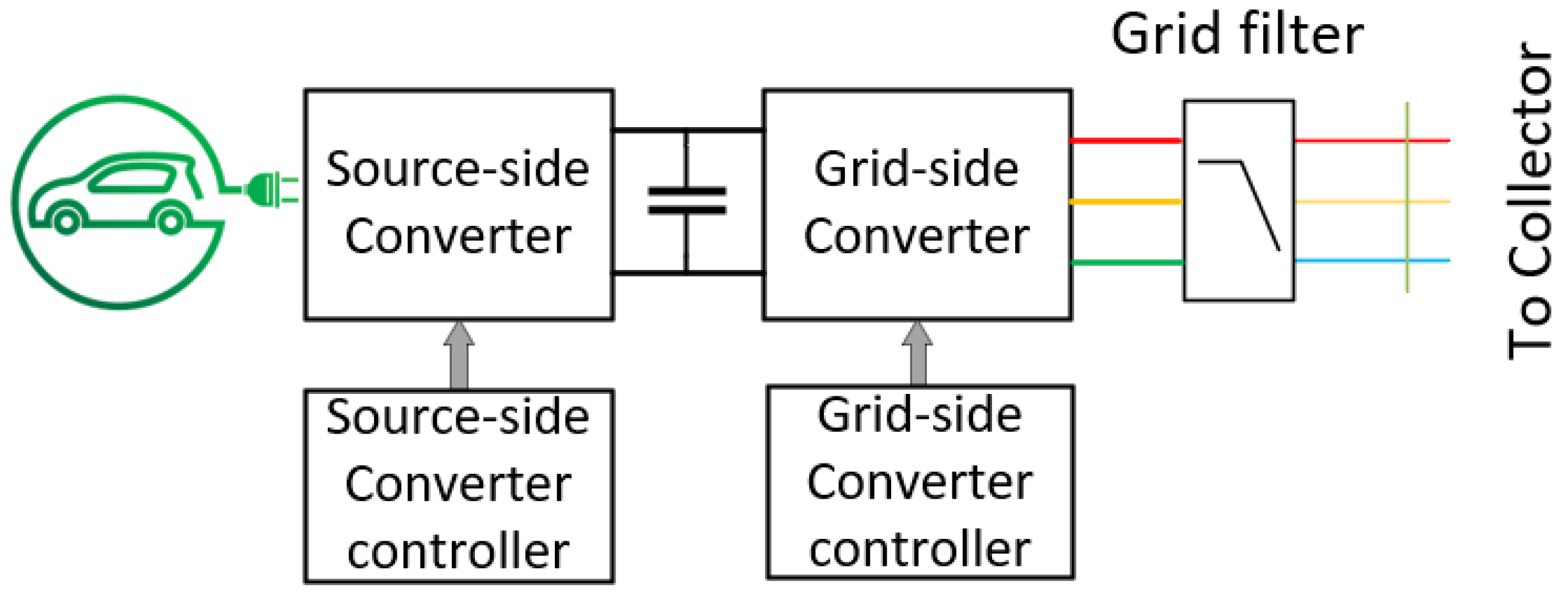
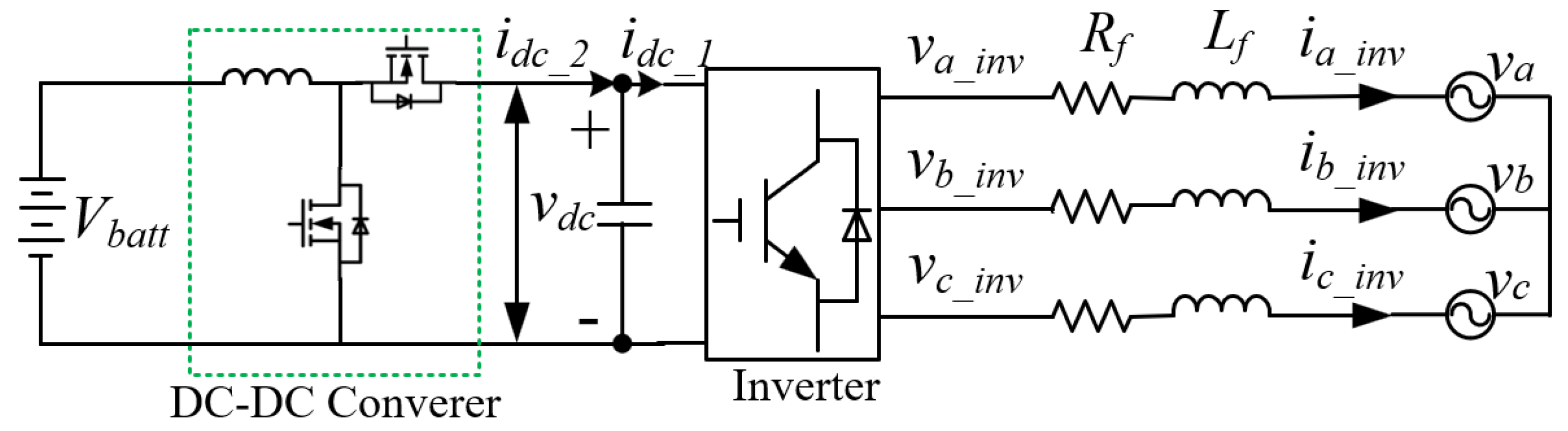
2.2. Inverter Interfaced EVGI System Model

In general, an EVGI system has a structure similar to wind turbine, solar, and battery system grid integration. The structure is an AC–DC–AC system for the wind turbine and a DC–DC–AC system for the other systems as shown in Figure 1. The system contains a source-side converter (AC–DC for wind turbine and DC–DC for photovoltaic (PV), battery, or EV), and a grid-side converter (DC–AC). The converters are connected via a DC link capacitor, and the whole system is connected to the grid via a grid-connected filter [42]. The control task for the source-side converter is to either extract maximum power (for PV panels or wind turbines) or charge/discharge the power management (for battery or EV). On the other hand, the grid-side inverter control action is to maintain constant DC link voltage, AC bus voltage, system frequency, supply reactive power to the grid according to the grid demand, etc. [43].
In a large-scale EVGI system, multiple EVs can be charged/discharged simultaneously. In that case, two types of connections are possible as shown in Figure 2. They are: (a) multiple source-side converters are connected in parallel to the DC link and a large grid-side inverter connects the system to the grid via a transformer (Figure 2a), (b) multiple EVGI systems are connected to the collector system, and an interconnection transformer is used to connect the system to the grid. For both cases, the operation of the source-side DC–DC converters remains unchanged, which is operating in both the constant current and constant voltage charging modes for efficient EV battery charging and discharging when required. If the large-scale EVGI system of case (a) is considered as a whole, the source-side converters can be assumed as a large converter connected to the DC link, whose power demand is constantly changing, and then case (a) and an individual EVGI system of case (b) become similar. Here, the source-side converter control action is to regulate the real power flow to satisfy the charging/discharging power requirement of the EVs.
The grid-side inverter can be used to provide different ancillary services by operating it in different modes. To do that, the controller of the grid-side inverter is designed using cascaded control loop theory where the inner loop controls the inverter current and the outer loops are used to control the different operating modes. For example, by adding a reactive power control loop, the system can support the grid with reactive power. Moreover, an additional outer control loop can enable the grid-side inverter to regulate the grid voltage at PCC. Moreover, real power and grid frequency control can be achieved by adding outer control loops at the source-side converter, in this case, the EV charge controller.

3. Grid Connected Inverter Modelling and Control

To model the grid-connected inverter for the EVGI system, it is mandatory to follow the step-by-step modeling at the subsystem level. In this section, the transient and steady-state inverter modeling and design of the inner and outer control loops in the d-q reference frame are presented.

3.1. Grid Connected Inverter Model in the d-q Reference Frame

Figure 3 shows the schematic of a GCI system, in which a DC-link capacitor is on the left and a three-phase voltage source, representing the voltage at the PCC with the AC system, is on the right. The figure also shows an L-type filer and the grid impedances which play a vital role in GCI modeling. Here, Lx and Rx represent the inductances and resistances of the filter and the grid.
The three-phase voltage balance across the inductor of the grid filter is:
v a b c _ i n v = R f i a b c _ i n v + L f d d t i a b c _ i n v + v a b c _ g
In the d-q reference frame, Equation (1) can be written as Equation (2), where ωs is the angular frequency of the grid voltage and vdq_x, idq_x are instantaneous space vectors of the voltages and currents.
v d _ i n v v q _ i n v = R f i d _ i n v i q _ i n v + L f d d t i d _ i n v i q _ i n v + ω s L f i q _ i n v i d _ i n v + v d _ g v q _ g
In the steady-state condition, Equation (2) becomes Equation (3) as
V d q _ i n v = R f I d q _ i n v + j ω s L f I d q _ i n v + V d q _ g
where Vdq_inv, Idq_inv, and Vdq_g denote the steady-state d-q vectors of inverter output voltage, current through the filter inductor, and grid voltage.
From Equation (4) the steady-state current flowing into the grid at the PCC is
I d q _ i n v = V d q _ i n v V d q _ g ( R f + j ω L f )
The power flowing from the IBR to the grid at the PCC can be achieved based on (5) and from the complex power equation as shown below
P P C C + j Q P C C = V d q _ g I d q _ g * = V d _ g I d q _ g *
In this case, Idq_g and Idq_inv are the same as the filter in an L filter. The value will differ if the LC or LCL filters are considered.

3.2. Vector Control Design of a Three-Phase GCI in the d-q Reference Frame

The standard vector control of a grid-connected inverter is developed by designing a nested loop structure, where the inner loop is a current control loop, and the outer loop can be DC-link, reactive power, or PCC voltage control. Generally, in GCI, the outer loop of the d-axis is used to control the DC link voltage, and other control loops such as reactive power, PCC bus voltage, etc. are applied in the q-axis. The controllers related to real power such as real power and frequency control are applied in the source-side converter. In order to derive the control loop transfer functions, a simplified structure of the grid-connected inverter is assumed, where an L filter is used for the grid interconnection, as shown in Figure 3.

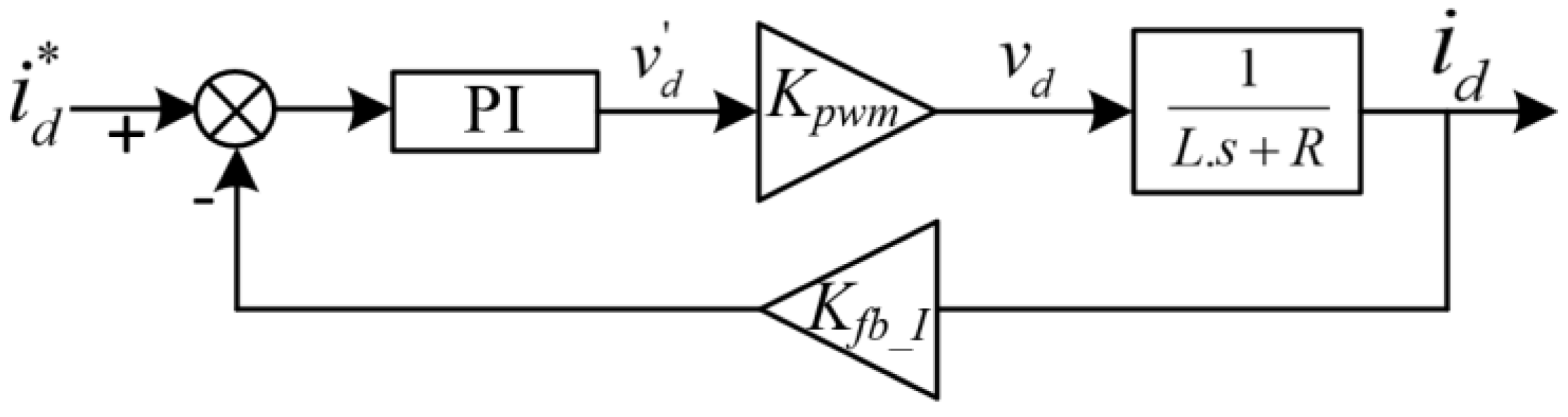
3.2.1. Inner Control Loop Design

The innermost control loop is the current control loop, which has the highest crossover frequency. To derive the current loop transfer function, KVL is applied in the circuit shown in Figure 3, and the equations are obtained in (2). Separating the d and q axis parameters from (2):
v d _ i n v = R f i d + L f d i d d t ω s L f i q + v d _ g
v q _ i n v = R f i q + L f d i q d t + ω s L f i d
In (7), the vq term is not considered as the synchronous reference frame is aligned to the vd axis, and thus the vq term is zero. The terms in the brackets are the d- and q-axis state equation represented in the output voltage and input current, and the rest of the terms are considered compensation terms. The transfer function of the inner current loop can be represented by a Laplace transformation of the terms in the bracket of (6–7).
I d q V d q _ i n v = 1 R + s . L
Using the transfer function stated in (8), the proportional integral (PI) controller can be tuned. The control loop design structure is given in Figure 4, where KPWM is the converter pulse width modulator gain, and KFB_I is the feedback path gain, such as the gain of the current sensor. The output voltage of the inverter at the PCC v d q _ i n v is given by [44],
V d q _ i n v = k P W M × v d q _ i n v *
Here, kPWM is the pulse with modulation gain calculated by the ratio of the PCC voltage and the controller output voltage.

3.2.2. Outer Control Loops Design

The outer control loops can also be designed using a similar approach as the inner current loop.
(a)
DC bus voltage control
For DC-bus voltage control, the transfer function can be derived from the DC-side and AC-side power balance principle. If the losses in the filter and grid are neglected, then the equation can be written as:
v d c i d c 1 = v d i d + v q i q
As the d-axis of the reference frame is aligned along the PCC voltage position, (10) can be rewritten as (11) below.
v d c C d v d c d t + i d c 2 = v d i d   d v d c d t = v d i d v d c C i d c 2 C  
In (11), if idc2 is considered a disturbance, then the transfer function of the DC voltage controller becomes:
v d c i d = v d v d c C s
By applying the transfer function in a similar structure as shown in Figure 4, the DC voltage controller can be designed. While performing the controller design, the current control loop gain is considered 1 due to the difference between the crossover frequencies of the two control loops.
(b)
Reactive power control
In a grid-connected inverter structure, the reactive power controller is assigned as an outer control loop of the q-axis current control. From the equation of reactive power, the transfer function can be derived.
Q = v q i d v d i q
If the controller is designed based on the q-axis current, then the d-axis current can be neglected. Thus, the reactive power control transfer function can be represented by,
Q i q = v d
(c)
PCC bus voltage control
The PCC bus voltage controller can be designed considering two cases. In the first case, the control loop can be assigned as an outer loop of the reactive power controller. Here, the output of the PCC bus voltage controller is the reference value of the reactive power controller. In the second case, the bus voltage controller can be applied directly by removing the reactive power controller. In this case, the output of the bus voltage controller is the reference value of the q-axis current controller.
For the first case, the transfer function can be written as,
v d Q = 1 i q
For the second case, the transfer function can be written as,
v d i q = Q i q 2
The control loops of the GCI can be organized as shown in Figure 5.
(d)
Real power and primary frequency control
For an EVGI system, the control actions related to the real power are assigned at the source-side converter. To control the real power flow, a control loop can be added outside of the current controller of the DC–DC converter. In this case, the real power controller will generate the current reference of the DC–DC converter.
The grid frequency control at the PCC can be performed in two ways: either by controlling the real power flow from the source side converter or by controlling the d-axis current of the grid connected inverter. In the first case, the power reference of the DC–DC converter is determined by a frequency control loop (P-f), and in the second case, a frequency control loop (Id-f) generates the d-axis current of the inverter. In both cases, the source is considered as an idle energy storage unit, ready to supply the required power. Generally, for case 1, a droop controller (P-f) is used to determine the real power required to maintain grid frequency at the nominal value. Figure 6 shows the cascaded control loops of the DC–DC converter and the P-f droop strategy applied to control the primary frequency of the grid.
As can be found in Figure 6b, for the linear P-f characteristic with a droop coefficient of mp, the injected/absorbed active power by EVs can be obtained as follows [45]:
Δ P = f p c c * f p c c m P = Δ P d i s c h > 0 i f f p c c < f p c c * 0 i f f p c c = f p c c * Δ P c h < 0 i f f p c c > f p c c *
where, Δ P d i s c h is the active power injected by EVs during the discharge mode, and Δ P c h is the active power absorbed by EVs during the charge mode.

4. EMT Simulation of Inverter-Interfaced EVGI System for Ancillary Services

An EMT simulation model of an inverter-interfaced EV grid integration system is built in Matlab/Simulink using the SimPowerSystems toolbox as shown in Figure 7. The model is used to analyze only the grid ancillary services. Thus, in the simulation model, a large-sized battery is used, which represents the available equivalent EV discharging power to the grid. The maximum output voltage of the battery is considered as 1100 Vdc. A buck-boost DC–DC converter is used to control the charging/discharging of the battery. The converter is controlled in both the constant current and constant voltage mode for the efficient charging of the battery. The DC bus voltage is maintained at 1500 Vdc. An inverter interfaced with a grid-connected LCL filter is used for the interconnection of the system to the grid. The DC–DC converter controller controls the real power flow, and the inverter controller maintains the DC bus voltage and reactive power flow. Both of the controllers employ cascaded loop control for safe and efficient operation. The power rating of the EVGI system is considered as 1.5 MW, where individual EVs can be of smaller size, considering the topology explained in Figure 2a. Table 1 shows the parameters used in the simulation.

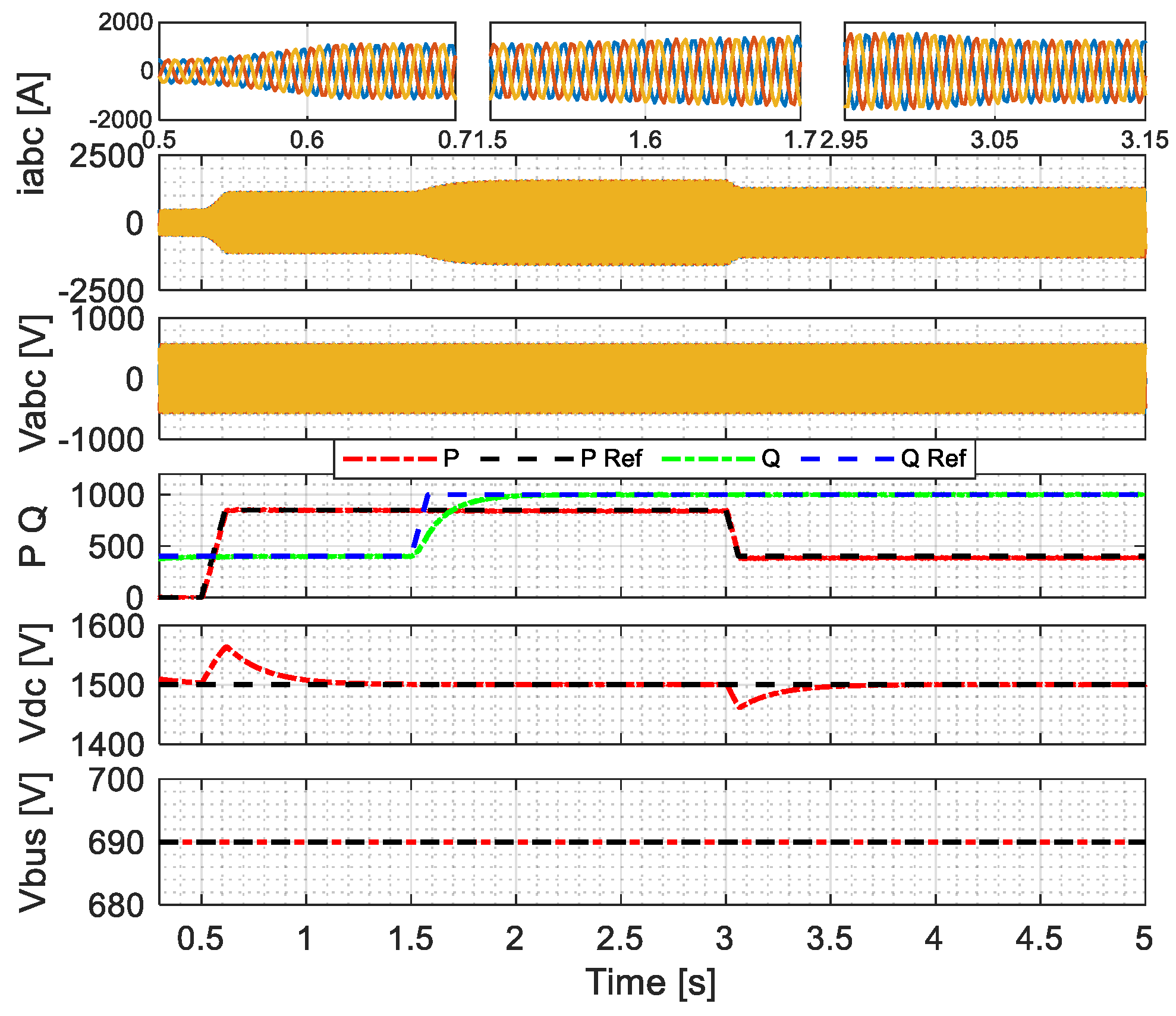
4.1. Real and Reactive Power Supply

The EVGI system is operated in the PQ control mode where the real power reference is given in the DC–DC converter and the reactive power reference is given at the inverter. The DC–DC converter controller calculates the required current to be extracted from the EV battery and operates in the constant current mode. The inverter controls the DC bus voltage at the d-axis and the reactive power at the q-axis as shown in Figure 6. The simulation results are shown in Figure 8, where the real power reference rises from 0 kW to 700 kW at 0.5 s and then drops to 450 kW at 3 s, whereas the reactive power goes from 450 kW to 800 kW at 1.5 s. The corresponding DC bus voltage, root mean square (RMS) voltage at the AC bus, and three-phase bus voltage and current are shown in the same figure. It can be seen that there is a slight fluctuation in the DC bus voltage during the real power change. It is because the AC power flows through the DC bus, whereas reactive power does not. In this mode of operation, the inverter is not operated to follow the AC bus voltage reference. Thus, if any disturbance in the AC bus voltage occurs, the output power might fluctuate from its reference values.

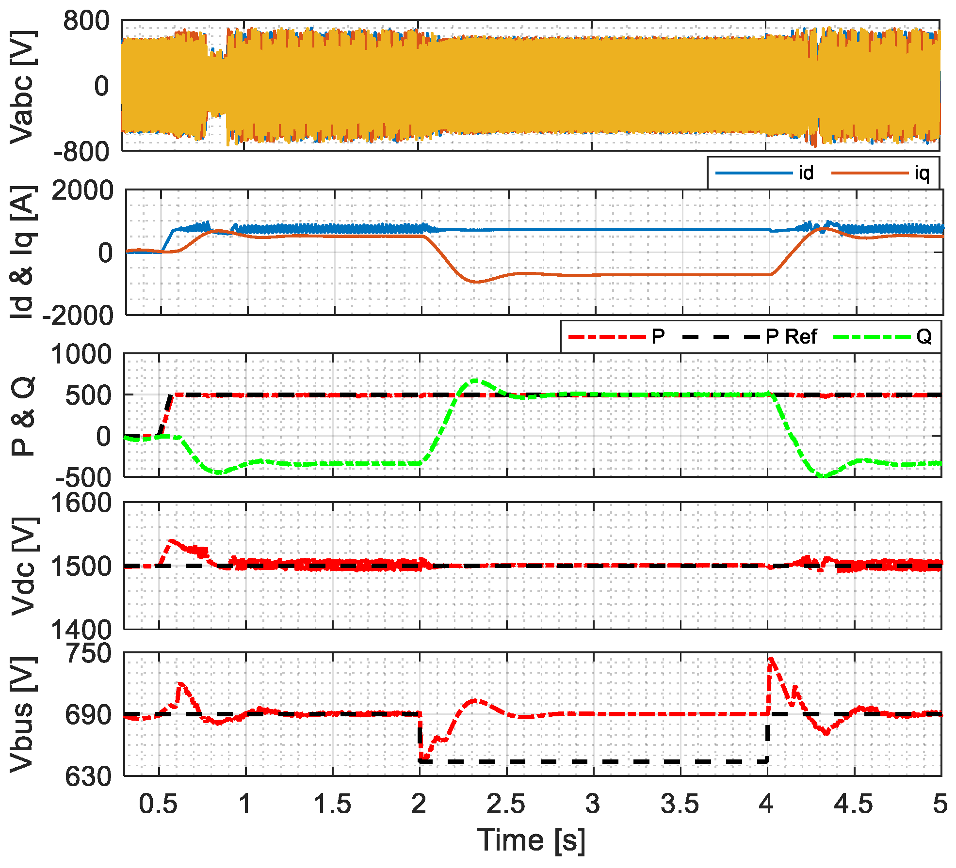
4.2. Voltage Support Using Reactive Power

To demonstrate the PCC voltage support using EVGI, the model is operated in PCC voltage control mode as shown in Figure 6. An outer voltage control loop is applied to generate the reactive power reference. The controller can be developed using Q-V droop or PI controllers. To demonstrate the voltage support using the EVGI system, a line-to-ground fault is introduced into the grid. As a result, a voltage sag occurs, and the PCC voltage falls from 690 V to 640 V. The EVGI system tries to recover the voltage sag by supplying more reactive power to the grid. The amount of reactive power supply depends on the PQ capability of the inverter and the requirement of the grid. Figure 9 shows the results for a voltage sag that is recovered by the inverter. The real and reactive power, DC bus voltage, PCC bus voltage, three-phase voltage, and current at PCC are shown in the figure. In the PCC bus voltage plot, a rise in voltage can be seen when the grid fault is cleared. It is due to the high reactive power supply from the EVGI system, as the system takes time to reduce its reactive power supply while the fault is cleared instantaneously.

4.3. Frequency Regulation

To perform frequency regulation operation, a droop controller is added at the DC–DC converter controller to control the real power flow. The P-f droop controller generates the real power reference according to the PCC frequency and then the required current reference is determined from the real power. Figure 10 demonstrates the frequency support results using the EVGI system. In this case, a drop in grid frequency of 1 Hz is introduced in the grid at the PCC. As the grid is strong and the frequency sag is performed by reducing the frequency, the EVGI system cannot bring back the frequency to its normal value. However, it can be demonstrated that the EVGI system can supply power to support the grid. Initially, the EVGI system was idle and did not supply any real or reactive power. When the frequency drop is introduced, the droop controller generated the real power reference. The real power controller generates the current reference value that needs to be extracted from the EV storage. Voltage sag also occurs when the frequency decreases. To handle the voltage drop, a Q–V droop controller is added at the q-axis control of the inverter, which generates the reactive power reference. From Figure 10, the frequency drop occurs at 2 s and is recovered at 3.5 s. The related d- and q-axis current as well as the power are also shown.

4.4. Harmonics Reduction

The harmonic components of the voltage and current that flow into the grid from an EVGI system can be reduced by using different filter configurations. Technically, this does not reduce the grid current/voltage harmonics but prevents the energy source from feeding the voltage/currents with high harmonics and thus helps the grid. In this part, the EVGI system is operated in PQ control mode with three different filter configurations, and the results are compared to show which filter provides the lowest harmonic distortion. Figure 11 shows the voltage and current results with their THD values. It shows that the LC filter has the highest voltage THD values and the LCL filter has the lowest THD. The LC filter performs better than the L filter but cannot outperform the LCL filters.

5. Performance Comparison

In literature, different grid ancillary services are proposed using various renewable energy systems as well as EVGI systems. Most of these proposed systems are focused on single-grid ancillary services, such as real and reactive power supply [29,30], voltage support [31], frequency regulation [15], or power quality improvement using an advanced controller [46] or filter mechanism [47]. Only a handful of research addressed multiple grid ancillary services using a single system [48]. A summary of the existing literature and a comparison of the proposed method with that literature for grid ancillary services are presented in Table 2. In the table, only the provided grid services are mentioned. The numerical values of improvement are omitted because it depends on the system capacity and the level of implementation.

6. Conclusions

In this study, an EVGI system is operated in different control modes to demonstrate that an EVGI system is capable of supporting the power grid rather than being a burden on it. With proper control technology, it can act as grid energy storage and provide supports such as real and reactive power compensation, voltage and frequency support, harmonics improvement, and so on. In this study, a large battery is used as the energy source, which represents the available power to be supplied to the grid when necessary. In the real scenario, a charging station with V2G capacity has multiple charging/discharging ports, which can be considered as a large-sized battery of which the capacity varies over time based on the number of EVs connected at the station. In this study, the charging mode of the storage system is not included as the main focus of this study is demonstrating the grid ancillary services using the V2G system. The grid-connected inverter of the V2G system is operated in multiple operation modes to ensure different grid ancillary services. The current control technology of commercial inverters does not incorporate multiple operation modes, which restricts the V2G systems from serving it for different grid services. Incorporating different operation modes in an EVGI system can be a potential way for serving the power grid. Moreover, the performance of each of these control techniques can be further improved by applying advanced artificial intelligence-based controllers. The current results prove that EV charging stations can be a good resource for the future grid if they can provide such services.

Author Contributions

Conceptualization, H.S.D. and S.L.; methodology, H.S.D. and M.N.; software, H.S.D. and M.N.; validation, H.S.D. and M.N.; investigation, S.L. and M.S.; data curation, M.S. and S.L.; writing—original draft preparation, H.S.D. and M.S.; writing—review and editing, S.L. and M.M.R.; supervision, S.L. All authors have read and agreed to the published version of the manuscript.

Funding

This research received no external funding.

Data Availability Statement

Not applicable.

Acknowledgments

The authors would like to thank The University of Alabama for their support with lab and library facilities. In addition, the authors would like to express their appreciation to those colleagues who have contributed to the completion of this work.

Conflicts of Interest

The authors declare no conflict of interest.

Nomenclature

The following abbreviations are used in this manuscript:
ACAlternating Current
DCDirect Current
DERDistributed Energy Resource
DGDistributed Generation
EMTElectromagnetic Transient
ESSEnergy Storage System
EVElectric Vehicle
EVGIElectric Vehicle Grid Integration
GCIGrid-connected inverter
G2VGrid to Vehicle
PCCPoint of Common Coupling
PVPhotovoltaic
RESRenewable Energy Source
RMSRoot Mean Square
SOCState of Charge
SOHState of Health
WTWind Turbine
V2GVehicle-to-Grid

References

  1. Shareef, H.; Islam, M.M.; Mohamed, A. A review of the stage-of-the-art charging technologies, placement methodologies, and impacts of electric vehicles. Renew. Sustain. Energy Rev. 2016, 64, 403–420. [Google Scholar] [CrossRef]
  2. Das, H.S.; Rahman, M.M.; Li, S.; Tan, C.W. Electric vehicles standards, charging infrastructure, and impact on grid integration: A technological review. Renew. Sustain. Energy Rev. 2020, 120, 109618. [Google Scholar] [CrossRef]
  3. Rahman, S.; Khan, I.A.; Amini, M.H. A Review on Impact Analysis of Electric Vehicle Charging on Power Distribution Systems. In Proceedings of the 2020 2nd International Conference on Smart Power & Internet Energy Systems (SPIES), Bangkok, Thailand, 15–18 September 2020; pp. 420–425. [Google Scholar] [CrossRef]
  4. Roy, R.; Alahakoon, S.; Arachchillage, S. Grid Impacts of Uncoordinated Fast Charging of Electric Ferry. Batteries 2021, 7, 13. [Google Scholar] [CrossRef]
  5. Leemput, N.; Geth, F.; Van Roy, J.; Delnooz, A.; Buscher, J.; Driesen, J. Impact of Electric Vehicle On-Board Single-Phase Charging Strategies on a Flemish Residential Grid. IEEE Trans. Smart Grid 2014, 5, 1815–1822. [Google Scholar] [CrossRef]
  6. Veldman, E.; Verzijlbergh, R.A. Distribution Grid Impacts of Smart Electric Vehicle Charging From Different Perspectives. IEEE Trans. Smart Grid 2014, 6, 333–342. [Google Scholar] [CrossRef]
  7. Calearo, L.; Thingvad, A.; Suzuki, K.; Marinelli, M. Grid Loading Due to EV Charging Profiles Based on Pseudo-Real Driving Pattern and User Behavior. IEEE Trans. Transp. Electrif. 2019, 5, 683–694. [Google Scholar] [CrossRef] [Green Version]
  8. Solanke, T.U.; Ramachandaramurthy, V.K.; Yong, J.Y.; Pasupuleti, J.; Kasinathan, P.; Rajagopalan, A. A review of strategic charging–discharging control of grid-connected electric vehicles. J. Energy Storage 2020, 28, 101193. [Google Scholar] [CrossRef]
  9. Mukherjee, J.C.; Gupta, A. A Review of Charge Scheduling of Electric Vehicles in Smart Grid. IEEE Syst. J. 2014, 9, 1541–1553. [Google Scholar] [CrossRef]
  10. Tan, K.M.; Ramachandaramurthy, V.K.; Yong, J.Y. Integration of electric vehicles in smart grid: A review on vehicle to grid technologies and optimization techniques. Renew. Sustain. Energy Rev. 2016, 53, 720–732. [Google Scholar] [CrossRef]
  11. Yilmaz, M.; Krein, P.T. Review of the impact of vehicle-to-grid technologies on distribution systems and utility interfaces. IEEE Trans. Power Electron. 2012, 28, 5673–5689. [Google Scholar] [CrossRef]
  12. Campbell, J. Ancillary Services Provided from DER; Oak Ridge National Lab.(ORNL): Oak Ridge, TN, USA, 2005. [Google Scholar] [CrossRef] [Green Version]
  13. Aziz, M. Electric vehicle utilization for ancillary grid services. AIP Conf. Proc. 2018, 1931, 030069. [Google Scholar] [CrossRef]
  14. Wu, C.; Mohsenian-Rad, A.-H.; Huang, J. Vehicle-to-grid systems: Ancillary services and communications. In Smart Grid Communications and Networking; Cambridge University Press: Cambridge, UK, 2012; pp. 91–108. [Google Scholar] [CrossRef]
  15. Hernández, J.; Sutil, F.J.S.; Vidal, P.; Rus-Casas, C. Primary frequency control and dynamic grid support for vehicle-to-grid in transmission systems. Int. J. Electr. Power Energy Syst. 2018, 100, 152–166. [Google Scholar] [CrossRef]
  16. Ravi, S.S.; Aziz, M. Utilization of Electric Vehicles for Vehicle-to-Grid Services: Progress and Perspectives. Energies 2022, 15, 589. [Google Scholar] [CrossRef]
  17. Yilmaz, M.; Krein, P.T. Review of benefits and challenges of vehicle-to-grid technology. In Proceedings of the 2012 IEEE Energy Conversion Congress and Exposition (ECCE), Raleigh, NC, USA, 15–20 September 2012; pp. 3082–3089. [Google Scholar] [CrossRef]
  18. Zhou, K.; Cheng, L.; Wen, L.; Lu, X.; Ding, T. A coordinated charging scheduling method for electric vehicles considering different charging demands. Energy 2020, 213, 118882. [Google Scholar] [CrossRef]
  19. Iqbal, S.; Xin, A.; Jan, M.U.; Rehman, H.U.; Masood, A.; Rizvi, S.A.A.; Salman, S. Aggregated Electric Vehicle-to-Grid for Primary Frequency Control in a Microgrid- A Review. In Proceedings of the IEEE 2nd International Electrical and Energy Conference (CIEEC), Beijing, China, 4–7 November 2018; pp. 563–568. [Google Scholar] [CrossRef]
  20. Saldaña, G.; San Martín, J.I.; Zamora, I.; Asensio, F.J.; Oñederra, O. Electric Vehicle into the Grid: Charging Methodologies Aimed at Providing Ancillary Services Considering Battery Degradation. Energies 2019, 12, 2443. [Google Scholar] [CrossRef]
  21. Wang, J.; Bharati, G.R.; Paudyal, S.; Ceylan, O.; Bhattarai, B.P.; Myers, K.S. Coordinated Electric Vehicle Charging With Reactive Power Support to Distribution Grids. IEEE Trans. Ind. Inform. 2018, 15, 54–63. [Google Scholar] [CrossRef]
  22. Pirouzi, S.; Aghaei, J.; Niknam, T.; Khooban, M.H.; Dragicevic, T.; Farahmand, H.; Korpas, M.; Blaabjerg, F. Power Conditioning of Distribution Networks via Single-Phase Electric Vehicles Equipped. IEEE Syst. J. 2019, 13, 3433–3442. [Google Scholar] [CrossRef] [Green Version]
  23. Aziz, M.; Oda, T.; Kashiwagi, T. Extended utilization of electric vehicles and their re-used batteries to support the building energy management system. Energy Procedia 2015, 75, 1938–1943. [Google Scholar] [CrossRef] [Green Version]
  24. Behravesh, V.; Keypour, R.; Foroud, A.A. Control strategy for improving voltage quality in residential power distribution network consisting of roof-top photovoltaic-wind hybrid systems, battery storage and electric vehicles. Sol. Energy 2019, 182, 80–95. [Google Scholar] [CrossRef]
  25. Kaur, K.; Kumar, N.; Singh, M. Coordinated Power Control of Electric Vehicles for Grid Frequency Support: MILP-Based Hierarchical Control Design. IEEE Trans. Smart Grid 2018, 10, 3364–3373. [Google Scholar] [CrossRef]
  26. Arias, N.B.; Hashemi, S.; Andersen, P.B.; Traholt, C.; Romero, R. V2G enabled EVs providing frequency containment reserves: Field results. In Proceedings of the 2018 IEEE International Conference on Industrial Technology (ICIT), Lyon, France, 20–22 February 2018; pp. 1814–1819. [Google Scholar] [CrossRef] [Green Version]
  27. Rahmani-Andebili, M. Spinning Reserve Capacity Provision by the Optimal Fleet Management of Plug-In Electric Vehicles Considering the Technical and Social Aspects. In Planning and Operation of Plug-In Electric Vehicles; Springer: Berlin/Heidelberg, Germany, 2019; pp. 49–74. [Google Scholar] [CrossRef]
  28. Izadkhast, S.; Garcia-Gonzalez, P.; Frìas, P.; Ramìrez-Elizondo, L.; Bauer, P. An aggregate model of plug-in electric vehicles including distribution network characteristics for primary frequency control. IEEE Trans. Power Syst. 2015, 31, 2987–2998. [Google Scholar] [CrossRef]
  29. Buja, G.; Bertoluzzo, M.; Fontana, C. Reactive Power Compensation Capabilities of V2G-Enabled Electric Vehicles. IEEE Trans. Power Electron. 2017, 32, 9447–9459. [Google Scholar] [CrossRef]
  30. Tan, K.M.; Padmanaban, S.; Yong, J.Y.; Ramachandaramurthy, V.K. A multi-control vehicle-to-grid charger with bi-directional active and reactive power capabilities for power grid support. Energy 2019, 171, 1150–1163. [Google Scholar] [CrossRef]
  31. Khalid, M.S.; Lin, X.; Zhuo, Y.; Kumar, R.; Rafique, M.K. Impact of Energy Management of Electric Vehicles on Transient Voltage Stability of Microgrid. World Electr. Veh. J. 2015, 7, 577–588. [Google Scholar] [CrossRef] [Green Version]
  32. Ebrahimzadeh, E.; Blaabjerg, F. Reactive Power Role and Its Controllability in AC Power Transmission Systems. In Reactive Power Control in AC Power Systems; Springer: Berlin/Heidelberg, Germany, 2017; pp. 117–136. [Google Scholar] [CrossRef]
  33. Sortomme, E.; El-Sharkawi, M.A. Optimal Scheduling of Vehicle-to-Grid Energy and Ancillary Services. IEEE Trans. Smart Grid 2011, 3, 351–359. [Google Scholar] [CrossRef]
  34. Tang, C.; Qu, H. Development of Ancillary Services in the Electricity Market of China and its Joint Market Optimization Model. IOP Conf. Series: Earth Environ. Sci. 2020, 571, 012029. [Google Scholar] [CrossRef]
  35. Almeida, P.R.; Soares, F.; Lopes, J.P. Electric vehicles contribution for frequency control with inertial emulation. Electr. Power Syst. Res. 2015, 127, 141–150. [Google Scholar] [CrossRef] [Green Version]
  36. Datta, M.; Senjyu, T. Fuzzy Control of Distributed PV Inverters/Energy Storage Systems/Electric Vehicles for Frequency Regulation in a Large Power System. IEEE Trans. Smart Grid 2013, 4, 479–488. [Google Scholar] [CrossRef]
  37. Teke, A.; Saribulut, L.; Tumay, M. A novel reference signal generation method for power-quality improvement of unified power-quality conditioner. IEEE Trans. Power Deliv. 2011, 26, 2205–2214. [Google Scholar] [CrossRef]
  38. Hong, Y.-Y.; Chen, Y. Placement of power quality monitors using enhanced genetic algorithm and wavelet transform. IET Gener. Transm. Distrib. 2011, 5, 461–466. [Google Scholar] [CrossRef]
  39. Wasiak, I.; Pawelek, R.; Mienski, R.; Gburczyk, P. Using energy storage for energy management and load compensation in LV microgrids. In Proceedings of the 2012 IEEE 15th International Conference on Harmonics and Quality of Power, Hong Kong, China, 17–20 June 2012; pp. 904–908. [Google Scholar] [CrossRef]
  40. Mikkili, S.; Panda, A. Real-time implementation of PI and fuzzy logic controllers based shunt active filter control strategies for power quality improvement. Int. J. Electr. Power Energy Syst. 2012, 43, 1114–1126. [Google Scholar] [CrossRef]
  41. Mahela, O.P.; Shaik, A.G. Topological aspects of power quality improvement techniques: A comprehensive overview. Renew. Sustain. Energy Rev. 2016, 58, 1129–1142. [Google Scholar] [CrossRef]
  42. Adib, A.; Mirafzal, B.; Wang, X.; Blaabjerg, F. On Stability of Voltage Source Inverters in Weak Grids. IEEE Access 2018, 6, 4427–4439. [Google Scholar] [CrossRef]
  43. Li, S.; Haskew, T.A.; Hong, Y.-K.; Xu, L. Direct-current vector control of three-phase grid-connected rectifier–inverter. Electr. Power Syst. Res. 2010, 81, 357–366. [Google Scholar] [CrossRef]
  44. Zhou, K.; Wang, D. Relationship between space-vector modulation and three-phase carrier-based PWM: A comprehen-sive analysis [three-phase inverters]. IEEE Trans. Ind. Electron. 2002, 49, 186–196. [Google Scholar] [CrossRef] [Green Version]
  45. Pilehvar, M.S.; Mirafzal, B. A Frequency Control Method for Islanded Microgrids Using Energy Storage Systems. In Proceedings of the 2020 IEEE Applied Power Electronics Conference and Exposition (APEC), New Orleans, LA, USA, 15–19 March 2020; pp. 2327–2332. [Google Scholar] [CrossRef]
  46. Irfan, M.; Rangarajan, S.S.; Collins, E.; Senjyu, T. Enhancing the Power Quality of the Grid Interactive Solar Photovoltaic-Electric Vehicle System. World Electr. Veh. J. 2021, 12, 98. [Google Scholar] [CrossRef]
  47. Javadi, A.; Al-Haddad, K. A Single-Phase Active Device for Power Quality Improvement of Electrified Transportation. IEEE Trans. Ind. Electron. 2015, 62, 3033–3041. [Google Scholar] [CrossRef]
  48. Zargar, B.; Wang, T.; Pitz, M.; Bachmann, R.; Maschmann, M.; Bintoudi, A.; Zyglakis, L.; Ponci, F.; Monti, A.; Ioannidis, D. Power Quality Improvement in Distribution Grids via Real-Time Smart Exploitation of Electric Vehicles. Energies 2021, 14, 3533. [Google Scholar] [CrossRef]
  49. Knezovic, K.; Martinenas, S.; Andersen, P.B.; Zecchino, A.; Marinelli, M. Enhancing the Role of Electric Vehicles in the Power Grid: Field Validation of Multiple Ancillary Services. IEEE Trans. Transp. Electrif. 2016, 3, 201–209. [Google Scholar] [CrossRef]
Figure 1. Schematic diagram of an EVGI system.
Energies 15 08623 g001
Figure 2. Schematic diagram of a large-scale EVGI plant: (a) multiple converters in source side connected to a single grid side converter, and (b) multiple EVGI systems connected together.
Energies 15 08623 g002
Figure 3. Schematic of an inverter connected to the grid via LCL filter.
Energies 15 08623 g003
Figure 4. Current loop control design.
Energies 15 08623 g004
Figure 5. Configuration of the grid-side inverter controller for different control actions.
Energies 15 08623 g005
Figure 6. (a) DC–DC converter control loops, (b) P-f droop control for frequency regulation.
Energies 15 08623 g006
Figure 7. Illustration of EMT simulation model of a grid-connected IBR.
Energies 15 08623 g007
Figure 8. Real and reactive power supply results.
Energies 15 08623 g008
Figure 9. PCC voltage control operation results.
Energies 15 08623 g009
Figure 10. PCC voltage control operation results.
Energies 15 08623 g010
Figure 11. Voltage and current output with THD values for L, LC, and LCL filters.
Energies 15 08623 g011
Table 1. Simulation parameters of the EVGI system.
ParametersValuesUnit
Rated power1.5MW
Rated PCC Voltage690Vrms
DC bus voltage1500V
LCL filter inductance (Lf, Lg)0.02mH
LCL filter resistance0.003
LCL filter Capacitance25µF
DC–DC converter inductor5mH
DC–DC converter inductor resistance0.003
DC–DC converter capacitor100µF
Table 2. Service benefit comparison of EVGI systems.
ReferencesReal and Reactive PowerVoltage RegulationFrequency RegulationPQ Improvement/Harmonic Reduction
Buja, G., et. al. [29]---
Tan, K.M., et al. [30]---
Khalid, M.S., et. al. [31]---
Hernández, J.C., et al. [15]---
Irfan, M., et al. [46]---
Javadi, A., and K. Al-Haddad [47]---
Zargar, B., et al. [48]--
Knezović, K., et al. [49]--
This paper
Publisher’s Note: MDPI stays neutral with regard to jurisdictional claims in published maps and institutional affiliations.

