1. Introduction
Exoskeletons are wearable devices that augment the physical strength of their wearers. Such devices are used in a wide variety of applications. The medical application constitutes rehabilitation of the motion and strength of the limbs of patients suffering from limb injuries and post-stroke gait dysfunction [
1,
2]. Furthermore, exoskeletons are used by industry workers to help them in lifting heavy objects and performing strenuous activities without risking fatigue and injuries [
3]. Soldiers, firefighters, and rescue workers can also benefit from exoskeletons for these reasons [
4,
5].
Exoskeleton devices of different types and capabilities have been developed by both researchers and industries in the past. A systematic review of past exoskeletons can be found in [
6]. This reference as well as an internal literature survey by the authors’ research group [
7] reveal that most of the powered exoskeleton devices being researched and available in the market are electro-mechanically driven.
However, hydraulic drives offer key advantages compared to electro-mechanical drives that can make them a better alternative drive technology for powered exoskeletons. Hydraulic drives are power-dense, which can allow a significant reduction in the mass and space occupied by the exoskeleton device. Moreover, hydraulic drives can be easily configured for energy recuperation functionality, which improves the efficiency of the drive, thus allowing a reduction in the size of the power source. Furthermore, hydraulic drives facilitate motion locking without power supply. Finally, damped motion is easily achievable with hydraulic drives, which allows for smooth and natural motion patterns.
Nevertheless, a number of challenges have prevented hydraulically driven exoskeletons from dominating the exoskeleton market. First, novel hydro-mechanical designs need to be developed that allow integration of the hydraulic drive in the exoskeleton device in a compact fashion. Second, miniature hydraulic components are needed to assemble a compact lightweight hydraulic drive. Third, fast and efficient control strategies appropriate for the hydraulic drives are needed for actuation of the exoskeleton. Last but not least, the image of hydraulics as a big, heavy, and obsolete technology needs revamping, which, until now, has prevented most researchers from pursuing hydraulic drives as an option for exoskeleton actuation.
One of the earliest hydraulically driven exoskeletons was the Berkeley Lower Extremity Exoskeleton (BLEEX), developed at the University of California, Berkeley [
8,
9,
10]. This exoskeleton augmented the power at the hip, knee, and ankle joints. Further improvements led to development of exoskeleton devices ExoHiker and ExoClimber, which were claimed to be more comfortable to the wearers [
11]. Around the same time, the company Sarcos unveiled its full-body exoskeleton XOS for military applications [
12]. While BLEEX used linear hydraulic actuators and mechanisms for motion transformation, XOS used rotary actuators directly at the limb joints [
13]. Recent works on hydraulically driven exoskeletons have focused on the control methods [
14,
15,
16,
17], development of compact hydraulic power units [
18], and alternate working fluids [
19]. However, a key limitation of these exoskeleton devices is that they use traditional servovalve-based resistance control, which is known for its poor efficiency. To overcome this limitation of traditional hydraulic systems, Kaminaga et al. proposed electro-hydraulic systems for actuation of joints in humanoid robots [
20] followed by knee exoskeletons [
21]. The design and control was focused particularly on achieving enhanced back-drivability [
22]. The knee joint power assist exoskeleton developed by them used rotary actuators (vane motors) at the knee joint [
23,
24] and consisted of additional passive joints to allow secondary knee movements [
25]. However, usage of hydraulic motors presents the challenges of internal leakages (leading to efficiency and controllability concerns) and low compactness. Therefore, recently, Lee et al. [
26] and Jiang et al. [
27] have explored electro-hydraulic systems with hydraulic cylinders instead of hydraulic motors for actuation of exoskeleton devices. In their recent knee exoskeleton design, Lee et al. [
28] added a multi-axial structure at the knee joint to minimize misalignments. Last, Sun et al. [
29] proposed a lightweight electrohydrostatic actuator (LEHA) for knee exoskeletons where they eliminated some accessory components of traditional EHA and custom-designed components to reduce the weight and volume of their exoskeleton device.
In recent decades, digital hydraulics has emerged as an innovative technology that promises several advantages compared to the traditional hydraulics technologies in terms of high force and power density, reliability, robustness, and inexpensiveness [
30]. These advantages make digital hydraulics an ideal candidate for actuation of exoskeleton devices, where compactness and robustness of the drive, lightness of the power source, and precision of motion are key requirements. The leg exoskeleton developed by Cao et al. [
31], which used switching control, can be considered as the earliest implementation of digital hydraulic concepts in the exoskeleton devices.
In recent years, the authors’ research group has made efforts to leverage the aforementioned advantages of digital hydraulics in development of lower limb exoskeleton devices. In 2017, the first design of a digital hydraulically driven knee exoskeleton was proposed [
7,
32]. This exoskeleton consisted of a digital hydraulic cylinder driving the knee joint via a four-bar linkage mechanism. A key limitation of this design was the need of multi-chamber cylinders to realize the digital cylinder, which are known to be expensive. In 2021, the authors proposed a novel design of knee exoskeleton that consists of a unique mechanism to enable digital actuation of the exoskeleton with two simple hydraulic cylinders instead of a multi-chamber cylinder [
33].
In the work presented in this article, the authors move towards realization of the aforementioned exoskeleton design. The design is first optimized with respect to its size and weight. Next, refined designs of each of the parts are developed, with a focus on their load carrying capabilities. Afterwards, a prototype of the exoskeleton device based on this design is fabricated. Finally, experimental studies are conducted to investigate the performance of the device and the control strategy proposed by the authors elsewhere [
34].
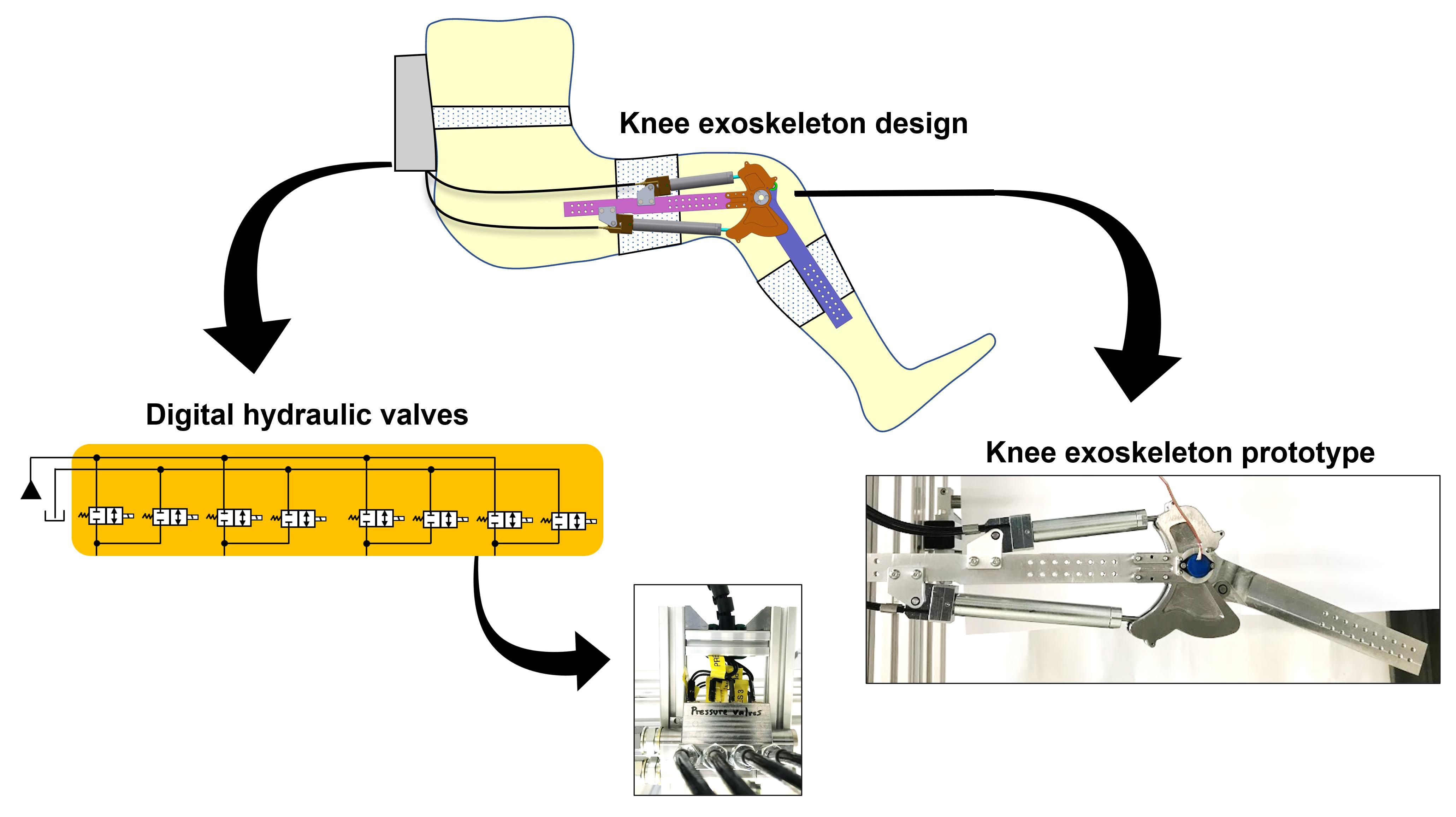
Overall, this article showcases successful realization of the concept of digital hydraulically driven exoskeletons. It presents to the research community and industry a power-dense hydraulic alternative to the electromechanically driven exoskeletons. Furthermore, this work brings digital hydraulics technology (and with it, its several advantages) into the field of hydraulically driven exoskeletons.
This article is divided into eight sections including this introductory section. The design of the knee exoskeleton device is presented in
Section 2.
Section 3 presents the details of the design optimization study. The information related to prototype development is presented in
Section 4. The control strategy proposed by the authors is briefly presented in
Section 5. The experimental tests and the results are described in
Section 6.
Section 7 presents a discussion of the work presented in this article in relation to past works. Finally, the key conclusions of this work are provided in
Section 8.
6. Experimental Tests
Testing of novel exoskeleton devices is typically carried out in two phases. The first phase involves testing the operation of the exoskeleton without human in the loop. This phase is important for safety purposes. Once the motion of the exoskeleton device is found to be satisfactory and safe, then the second phase of testing is conducted with human wearing the exoskeleton device.
In this work, first-phase tests are conducted. The details of the experimental setup and test results are presented in the following subsections.
6.1. Experimental Setup
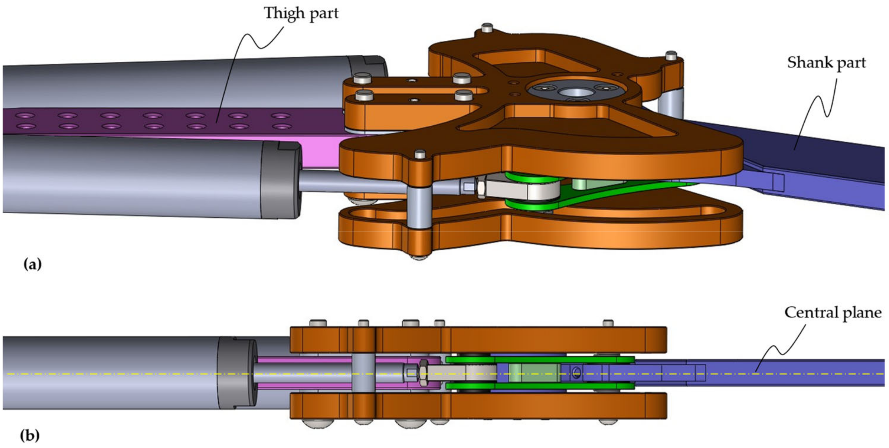
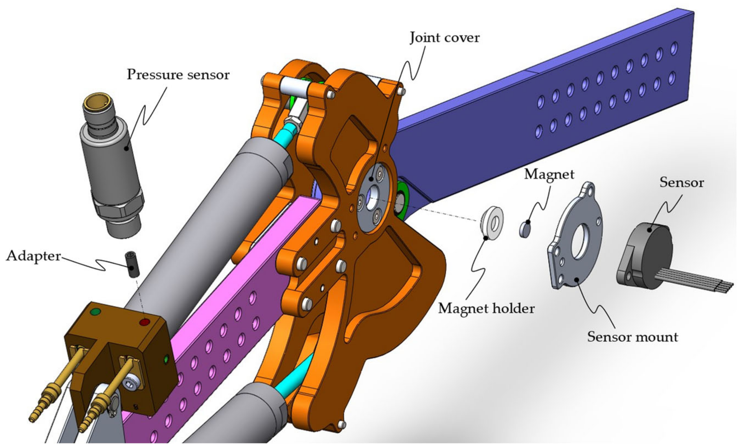
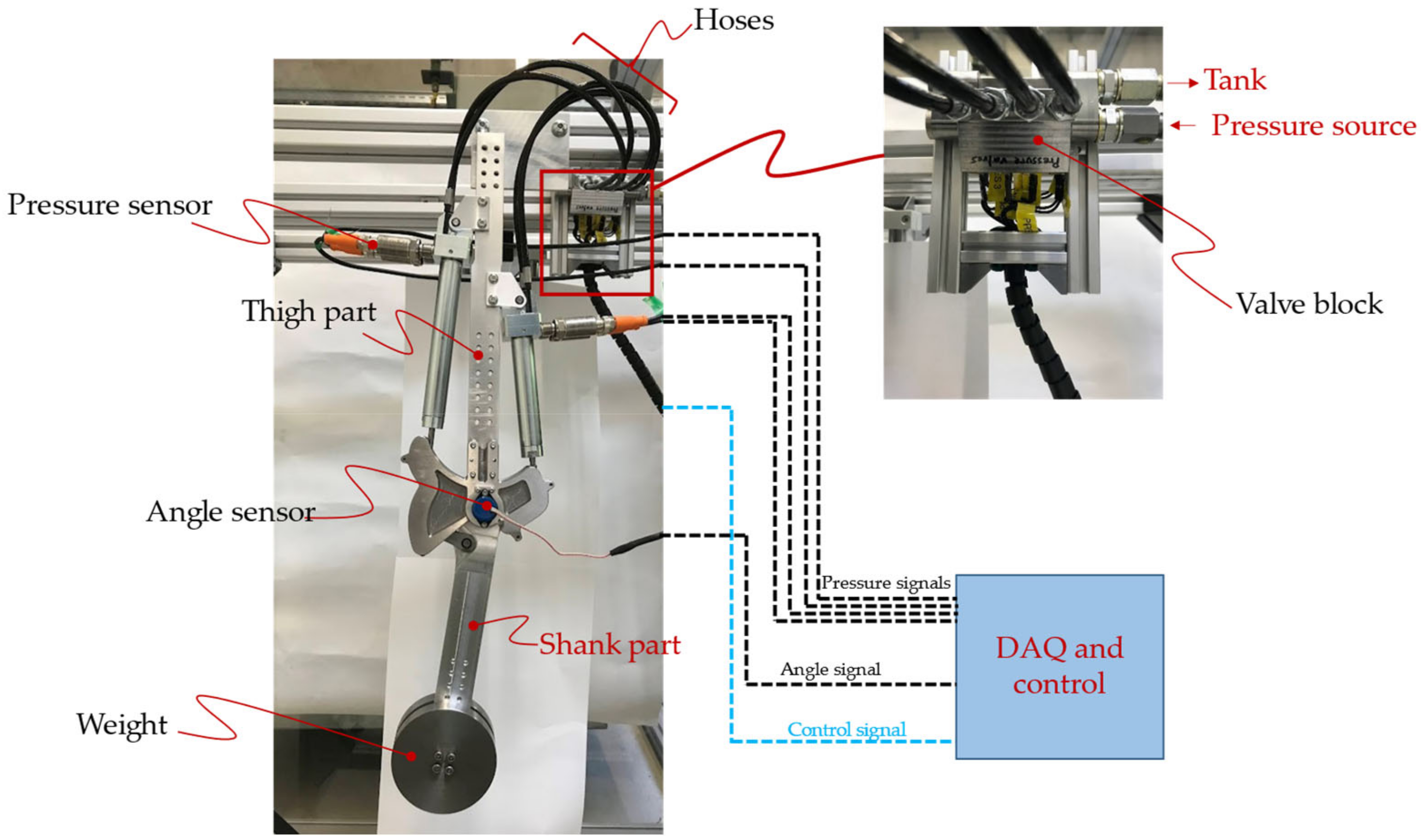
The exoskeleton prototype is mounted on a test rig, as shown in
Figure 27. Two weights (1 kg each) are added on each side of the shank part to partially simulate the weight of the shank and foot of the wearer. The angle sensor attached to the knee joint measures the knee angle and transmits it to the data acquisition and control system. As described in
Section 5.2, the measured knee angle is used in the motion control strategy. The pressure sensors are also present in the test setup for monitoring purposes. The details of the sensors used in the test setup are reported in
Table 4.
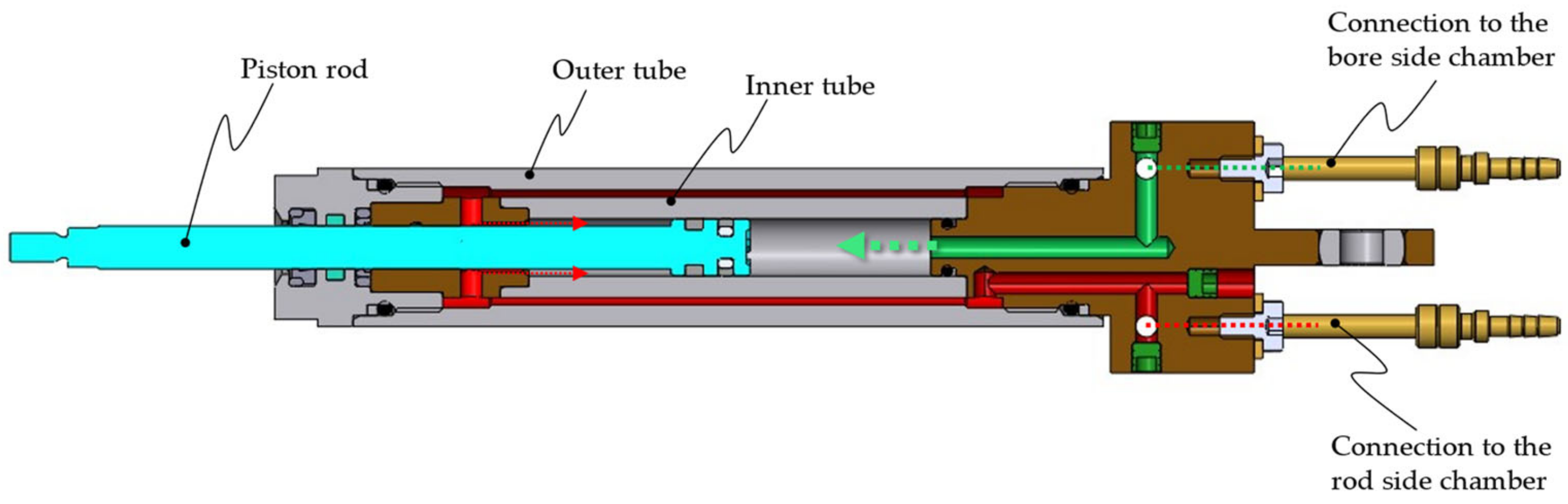
The hydraulic power supply used in this work is a traditional supply system available to the authors that is capable of supplying flow at a preset pressure level. For an exoskeleton device that would eventually be worn by a user, the hydraulic power supply will comprise a miniature pressure-controlled electrohydraulic pump that could fit in the backpack of the user. Focus on this aspect of hydraulic power supply will be a task for the future.
Since the weights attached to the shank part are 2/5th of the typical weight of the shank and foot [
35], the supply pressure is also set to 2/5th of the design pressure, i.e., 80 bar.
For data acquisition and control, a B&R X20 PLC system [
45] is chosen. The system is flexible and can easily be adapted for any given I/O configuration, e.g., analog signals from the pressure sensors, bus connections, and driving the digital valves via “boost and hold” command [
42].
The controller model described in
Section 5.2 is implemented in MATLAB/Simulink environment. The Simulink model is then imported into the programming tool “Automation Studio” from B&R using “Automation Studio Target for Simulink” software (which allows automatic code generation from the Simulink model). Finally, “Automation Studio” establishes a TCP/IP connection with the B&R target system.
During tests, the measurements are recorded with a sampling time of 0.5 milliseconds, and postprocessing is completed in the MATLAB environment.
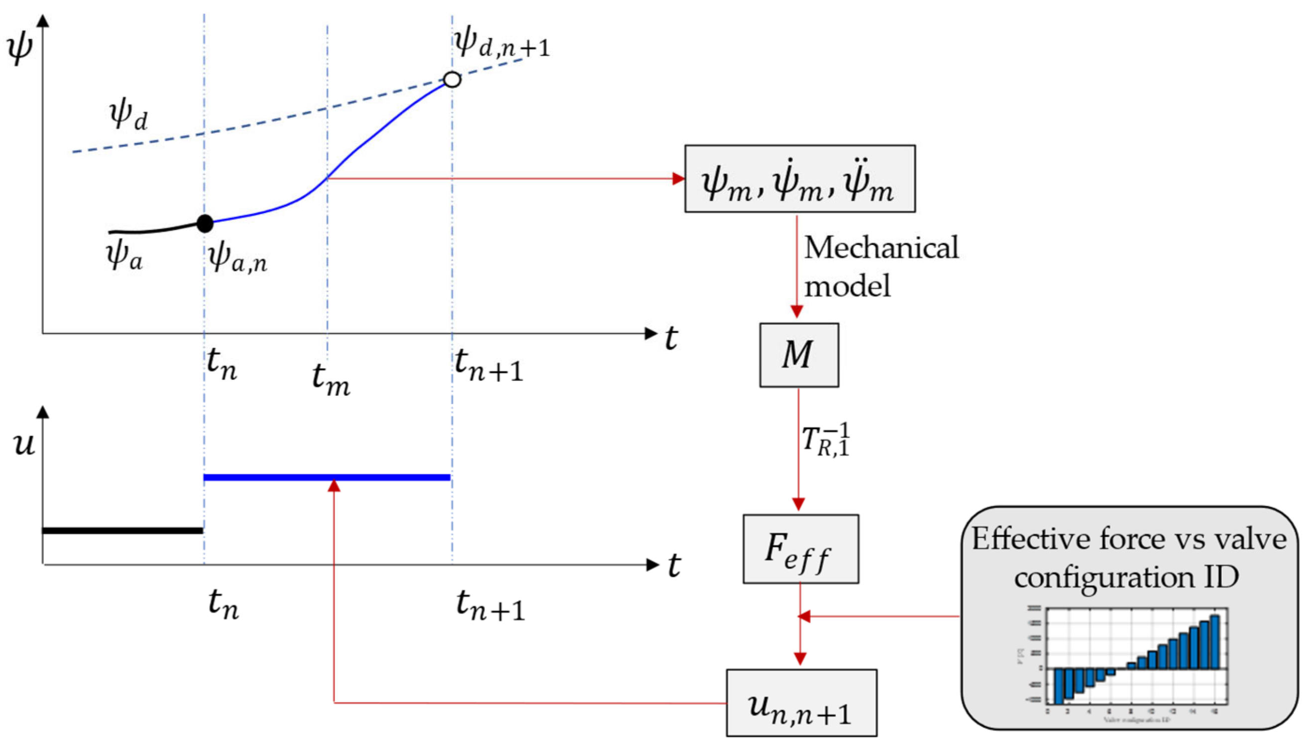
6.2. Test Trajectory
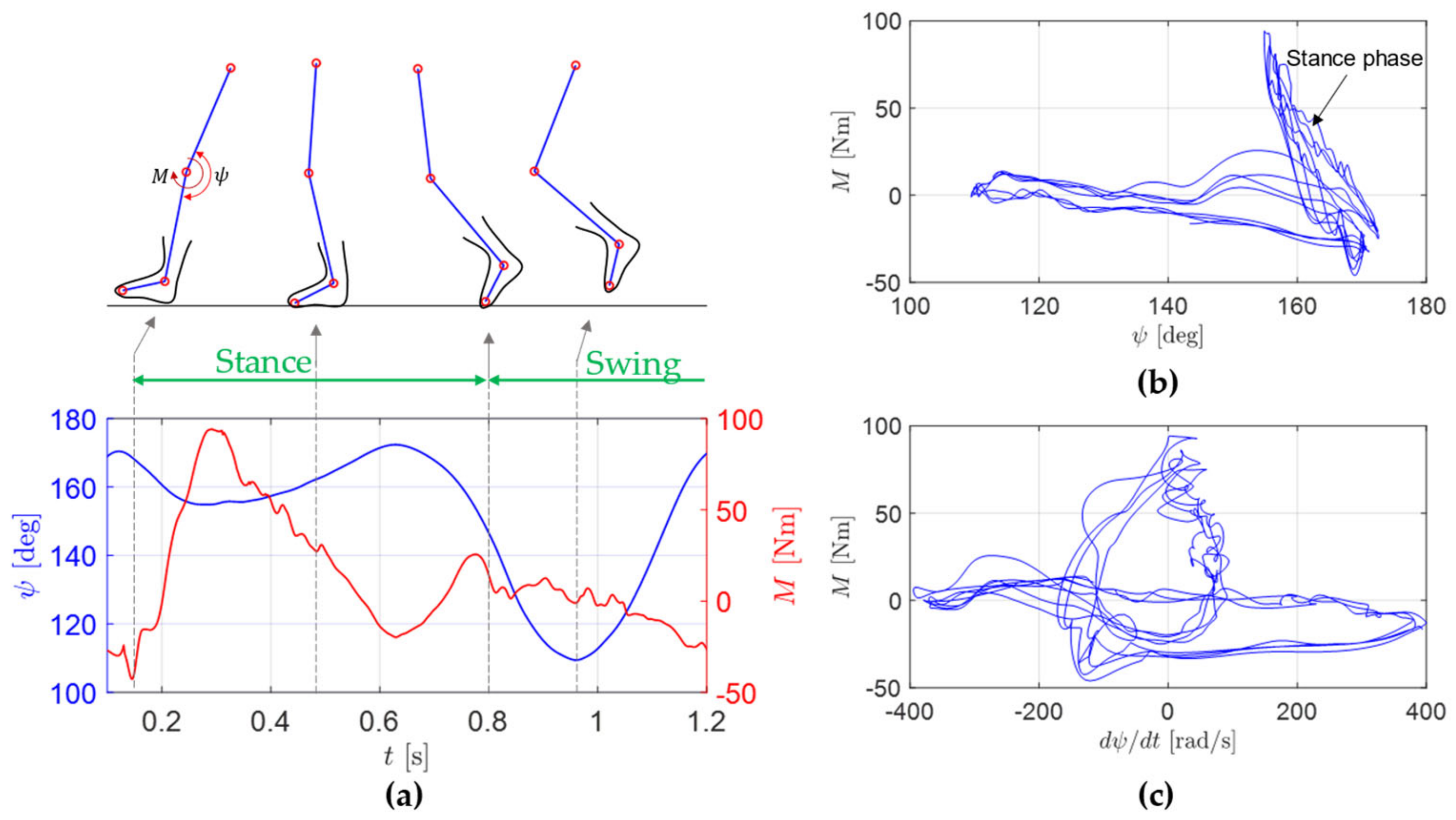
The goal of the tests in this work is to validate the motion control strategy proposed by the authors for the swing phase (
Section 5.2) and the capability of the exoskeleton device to follow the desired motion. As shown in
Figure 28a, the knee angle trajectory in the swing phase can be approximated via a cosine curve. The equation describing this curve is:
This cosine curve is repeated to generate a test trajectory (
Figure 28b), which is then used in the experiments.
6.3. Test Results
The experiments are conducted on the test setup using the control strategy described in
Section 5.2. The only difference is the mechanical model, which, for the case of the test setup, is:
where
is the moment of inertia of the weights around the knee joint,
is the torque delivered by the hydraulic drive,
is the mass of the weights,
is the acceleration due to gravity, and
is the distance of the center of mass of the weights from the knee joint. Here, the inertia of the shank part is neglected since it is much lighter (~8 times) compared to the weights.
The exoskeleton device is asked to follow the test trajectory detailed in
Section 6.2. The controller time step is set to 50 milliseconds.
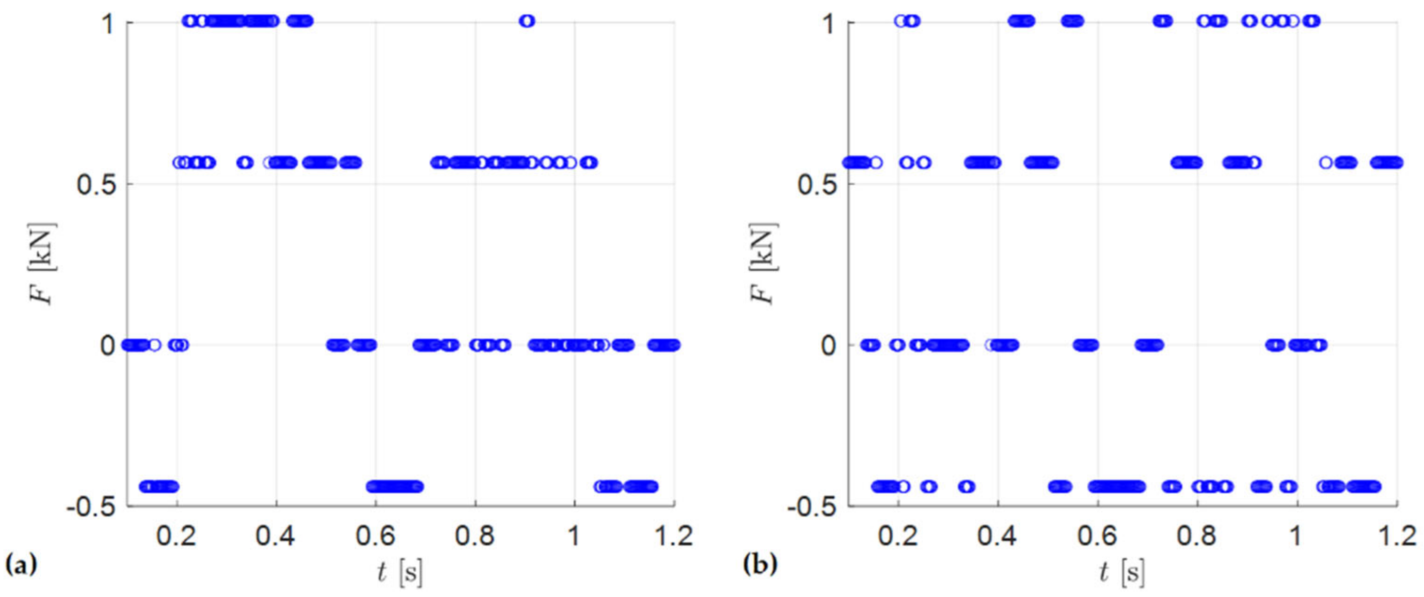
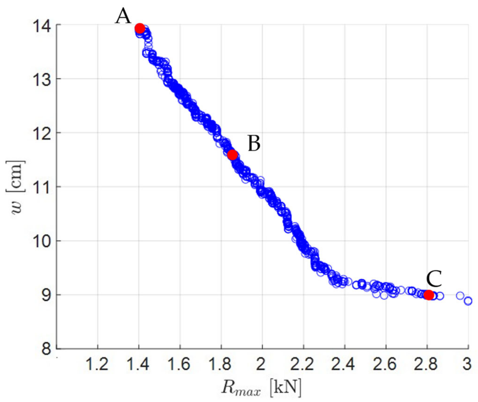
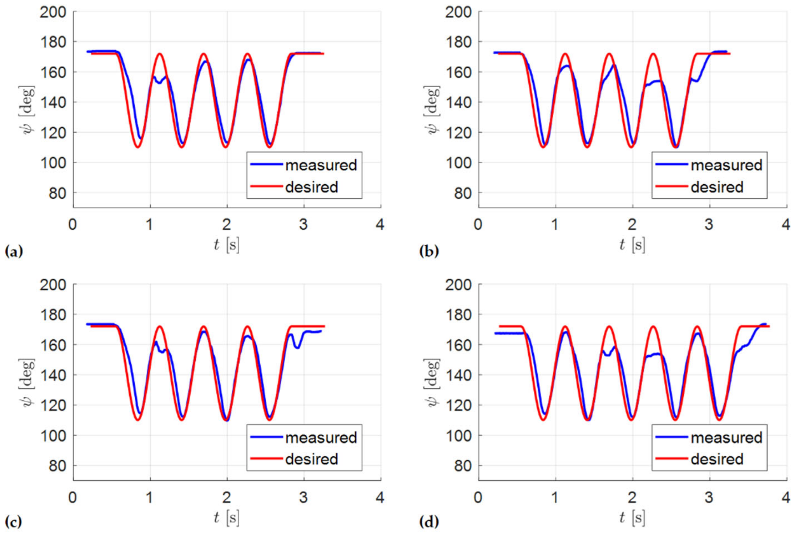
Figure 29 shows the results from four sets of experiments. The conditions for the experiments are identical except for the initial knee angle and the pressure level of the source, which varies slightly between the experiments. The results indicate that the exoskeleton device is able to track the desired trajectory reasonably well. However, at some instances, it fails to reach the full knee extension as desired.
For a quantitative analysis of the results, the error between the measured trajectory and desired trajectory is defined as:
The mean error (
), its standard deviation (
), and maximum error (
) for the four sets of measurements are reported in
Table 5. The error statistics are very similar across the experiments. Mean error of
is deemed to be tolerable by the user. However, the maximum error of
is of concern, which is caused by the inability of the device to reach full extension for some instances.
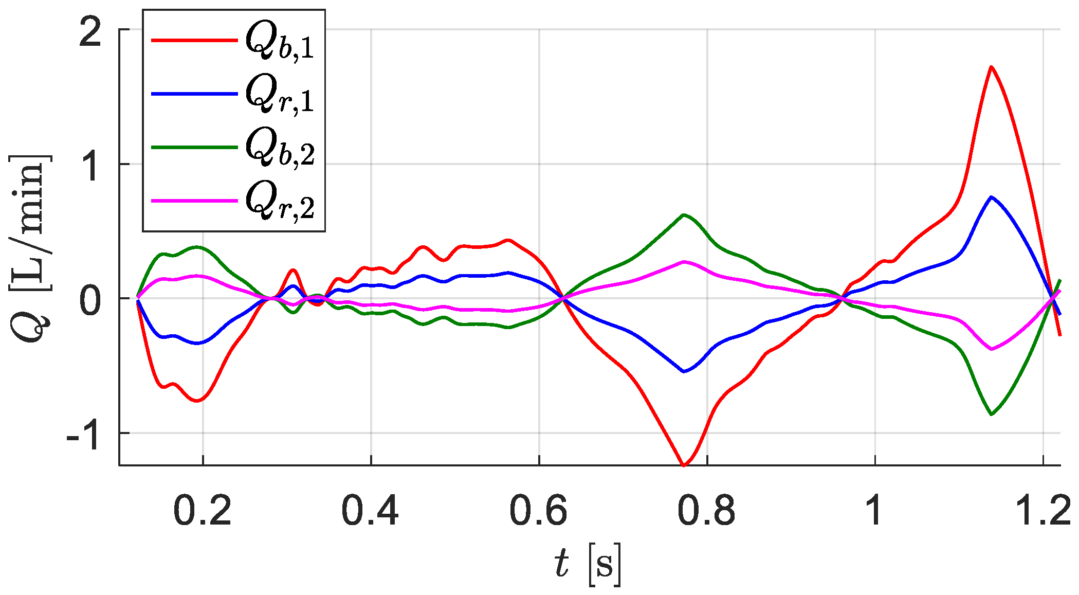
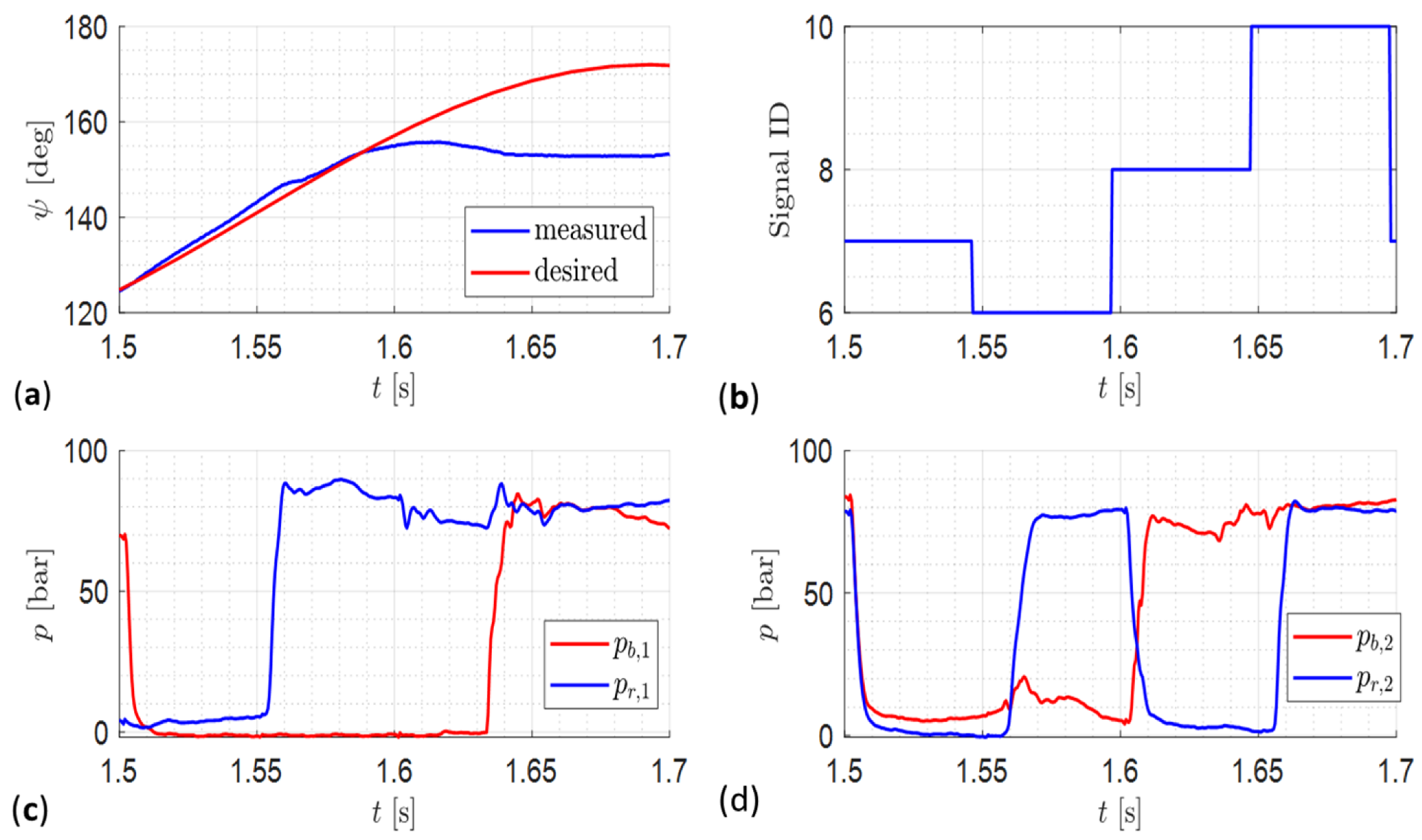
A closer investigation into this discrepancy is illustrated via
Figure 30. At
s, the controller commands the valve configuration of
. As per
Table 3, the state of the cylinder chambers should be:
. However, as per
Figure 30c,
chamber starts to pressurize only at
s. Thus, for
ms, the state of the chambers is
, which corresponds to
. Consequently, as per
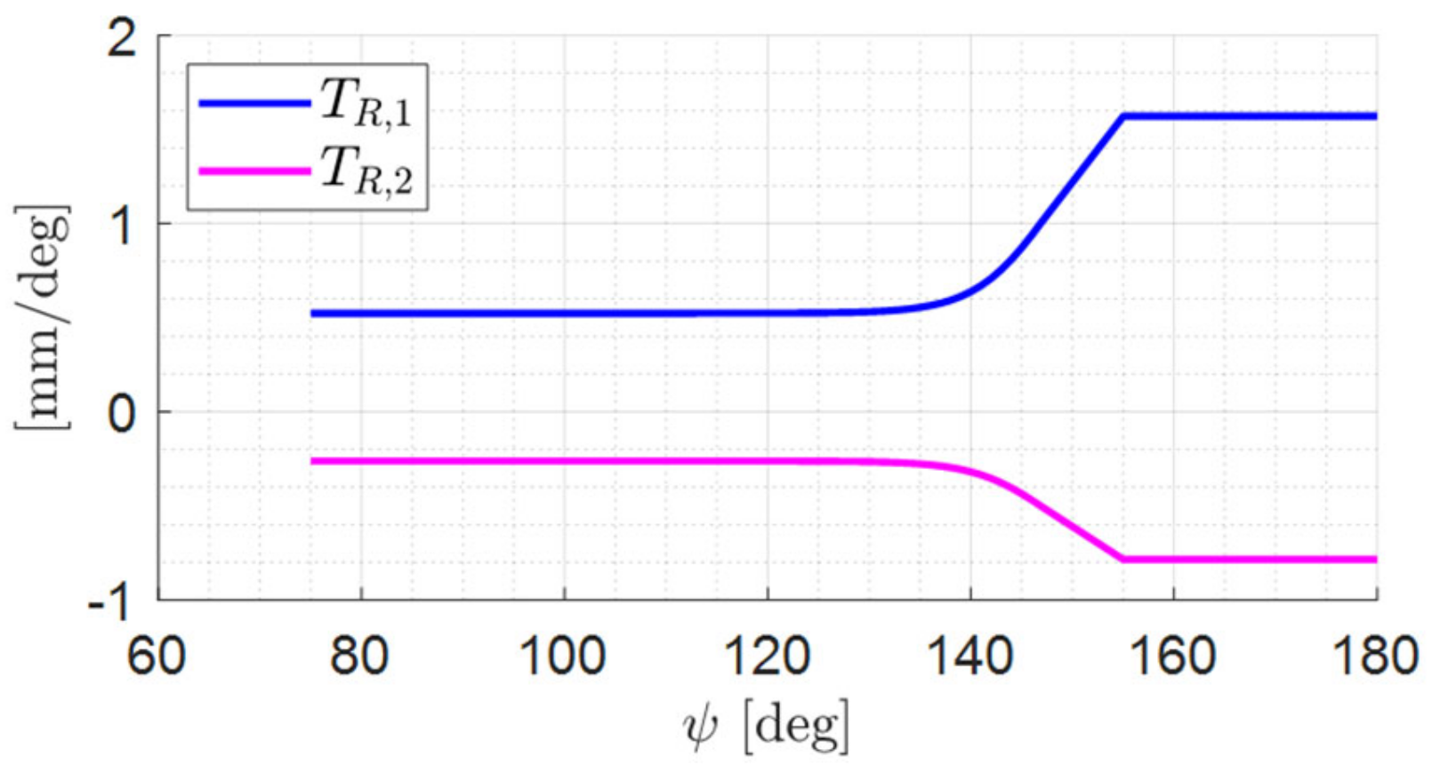
Figure 12, instead of negligible force (
), the drive delivers very high negative force, resulting in a sharp deceleration of the knee angle and a deviation from the desired trajectory.
The delayed pressurization of
chamber is explained via the following arguments. During knee extension,
chamber expands quickly. As gravity is helping the extension, the force needed from the drive is negative. From
Figure 12, the valve configuration will remain below 7, i.e.,
chamber remains connected to the tank. Thus,
is a fast-expanding chamber connected to tank, which needs high flow from the tank so that the chamber pressure can remain close to the tank pressure. However, the smallness of the valve (described in
Section 4.3) restricts the amount of flow from the tank to the chamber. Consequently, the chamber pressure goes sub-atmospheric. Due the typical presence of entrained air in the fluid, its bulk modulus falls severely at such low pressures. Thus, when the chamber is connected to the pressure source, it takes more time to pressurize.
It is notable that this discrepancy in trajectory tracking only occurs in a specific situation near the end of knee extension when the controller commands a valve configuration that requires pressurized . At different instances, when the controller commands other valve configurations that do not require pressurization of this chamber, the discrepancy does not appear.
This issue can be addressed by using a larger valve that allows high enough flow to ensure that the pressure in chamber does not fall below the atmospheric pressure. However, the availability of larger valves in a compact arrangement remains a challenge, and, thus, other alternatives are needed to be investigated in the future.
7. Discussion
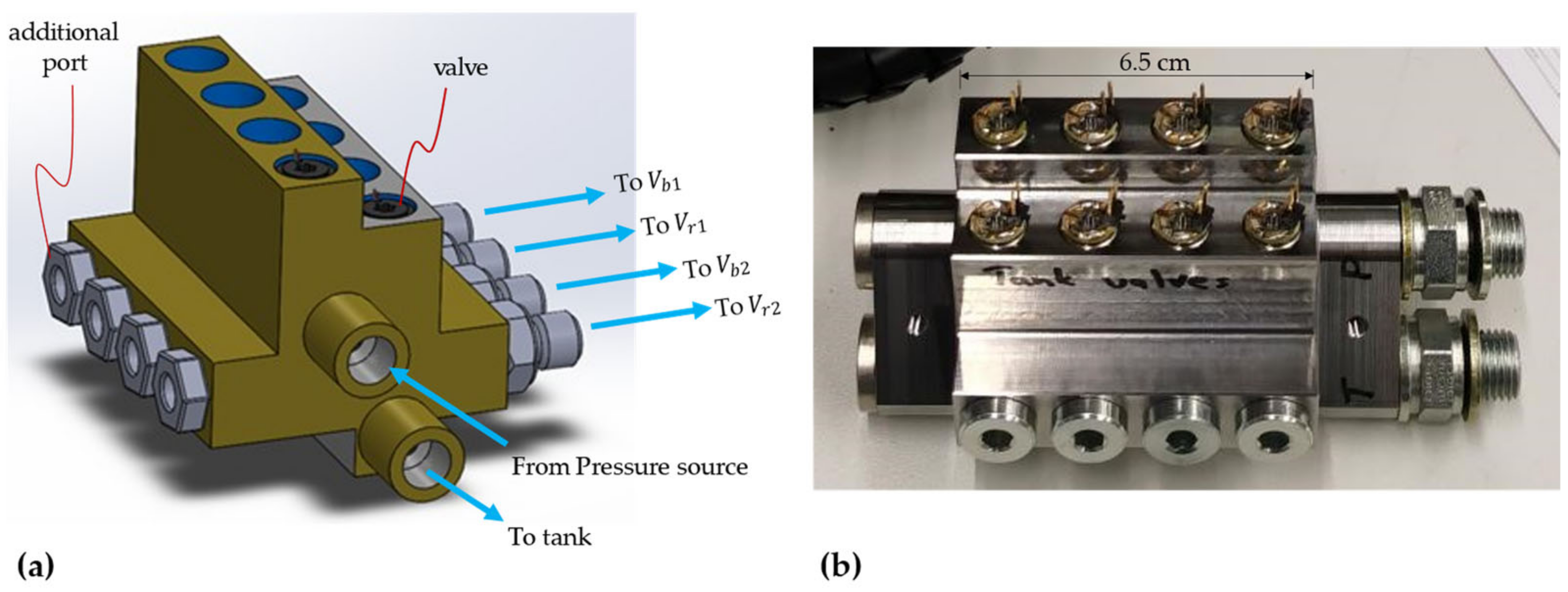
The digital hydraulically driven knee exoskeleton developed and tested in this work presents a significant advancement in terms of using hydraulics technology for actuation of exoskeleton devices. Compared to the traditional hydraulics technology used by past exoskeletons [
8,
12,
14,
15,
18], the digital hydraulically driven exoskeleton device promises higher compactness, efficiency, and robustness. The compactness is illustrated in this work via the size of the valve block containing eight 2/2-way valves. Since the operations performed by the device in this work and the past devices in the literature are different, a direct efficiency comparison is not possible at this stage. However, the next phase of full gait cycle testing with user-in-loop will allow this direct efficiency comparison.
Another key advantage of the exoskeleton device presented in this work is that, since it is designed for paraplegic patients, it is capable of supplying 100% of the torque requirement at the knee joint. In contrast, most of the past works on exoskeleton development deal with partial disability or power augmentation. Thus, the devices developed are capable of supplying only up to 30% to 50% of the knee torque [
15,
23].
Since paraplegic patients are unable to control their leg, the controller of the exoskeleton device developed in this work makes all the decisions in the gait cycle. A simplified model predictive controller is proven (in this work and authors’ past works [
34]) to be sufficient for this task. In contrast, the devices developed for patients with partial disability and for power augmentation should account for the interaction between the force supplied by the human and the device. Thus, researchers working on such devices have used a variety of complex control strategies, ranging from cascade force control [
14] to joint torque control [
15] and repetitive learning control [
16].
In the future, the authors would also like to extend the use case of their exoskeleton device to patients who can partially control their knee. A key challenge in this regard is identification of the motion intent of the wearer. Several approaches for motion intent identification have been proposed by other researchers [
46]; however, one compatible with the drive system used in this work needs to be investigated.
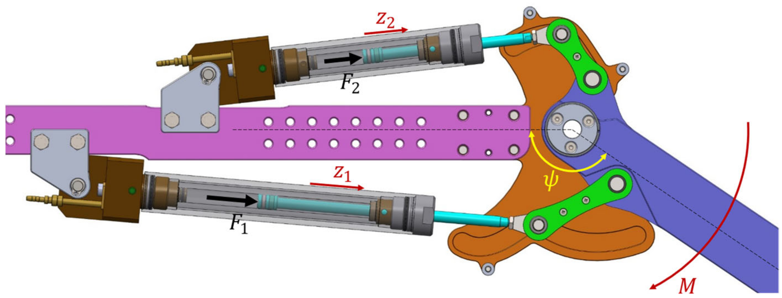
The final discussion point is that of the prototype weight. The first-generation prototype developed in this work has been observed to be too heavy for users’ comfort (2.8 kg). In contrast, Sun et al.’s LEHA weighs 2.5 kg (including the power supply) [
29]. The reason behind this high weight (despite the optimized design) primarily lies in the twin-tube cylinder design. Such a design unnecessarily increases the amount of material used, thus increasing the weight (the cylinders weigh 0.62 kg and 0.54 kg, respectively). However, this is an obvious limitation of using off-the-shelf components. Sun et al. were able to achieve a low weight of their device by custom-designing the components. In the future, the prospects of inhouse manufacturing of cylinders will also be explored by the authors, which could address the weight issue and also enable an area ratio of 4:1, which is ideal for uniform force stepping of the digital drive. Furthermore, the simplicity of the guide plate design results in its high weight (0.4 kg each). In the next generation of the prototype, the guide plate design could be further optimized by developing a truss-frame-type structure, which will significantly lower its weight.
8. Conclusions
This article presents development and first-phase testing of a novel digital hydraulically driven knee exoskeleton prototype, the idea of which was conceived by the authors in their previous works. Via a multi-objective optimization study, a design is developed that is optimal with respect to its size and weight. The designs of the linkage parts are further refined while ensuring that each part can safely support the load exerted on it over a typical operational cycle. Subsequently, the prototype is manufactured and assembled with procured hydraulic cylinders, valves, and sensors. Finally, first-phase testing (without human) is conducted, where the prototype is mounted on a test stand and the controller is tasked with following a given trajectory that resembles the swing motion in a typical gait cycle. The results indicate that the prototype is able to track the desired motion, except with occasional discrepancies at full knee extension.
In the future, investigations to address the aforementioned discrepancy need to be conducted. These should be followed by testing the full gait cycle operation with a human in the loop.
Overall, the novel digital hydraulically driven knee exoskeleton device prototyped and tested in this work is a significant step towards bringing the advantages of digital hydraulics technology to the field of hydraulically driven exoskeleton devices. This can pave the way for widespread adoption of power-dense hydraulics technology in actuation of exoskeletons. The resulting compact lightweight exoskeleton devices will ultimately improve the comfort level of the wearers.
Furthermore, this work also showcases the gaps in the current hydraulics components’ availability (e.g., miniature yet efficient valves and lightweight cylinders), which has historically hindered usage of hydraulics technology in exoskeleton actuation. This can be interpreted as an exciting opportunity for the industry and the research community for further research and development in this regard.


 ,
, 


