
Numerical Study on Spreading and Vaporization Process of Liquid Nitrogen Droplet Impinging on Heated Wall


Abstract
:1. Introduction
2. Numerical Model
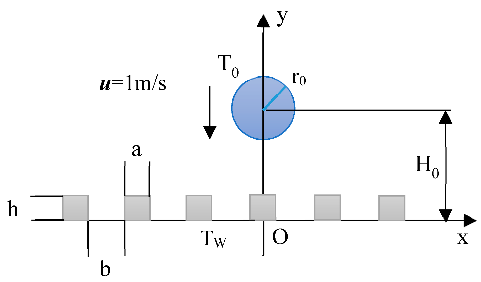
2.1. Physical Model
- The effect of temperature on physical properties was disregarded.
- The interface temperature was assumed to be at saturation temperature.
- Heat generation induced by friction was not considered.
- The gas–liquid pair velocity was small, so it could be regarded as incompressible flow.
2.2. Numerical Model
2.2.1. Governing Equations
2.2.2. Vaporization Model
2.2.3. Boundary Condition
3. Model Validation
3.1. Grid Independence Verification
3.1.1. Grid Independence Verification of Phase Transition Model
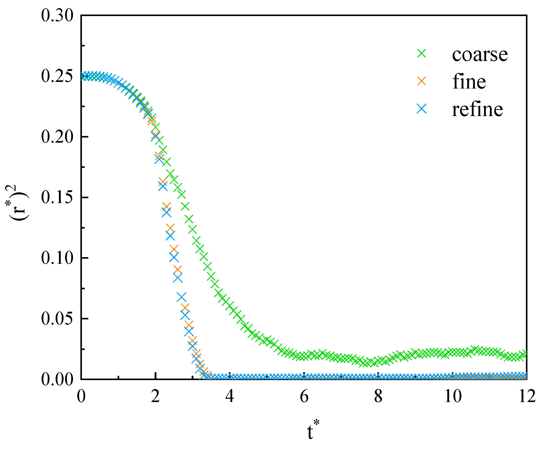
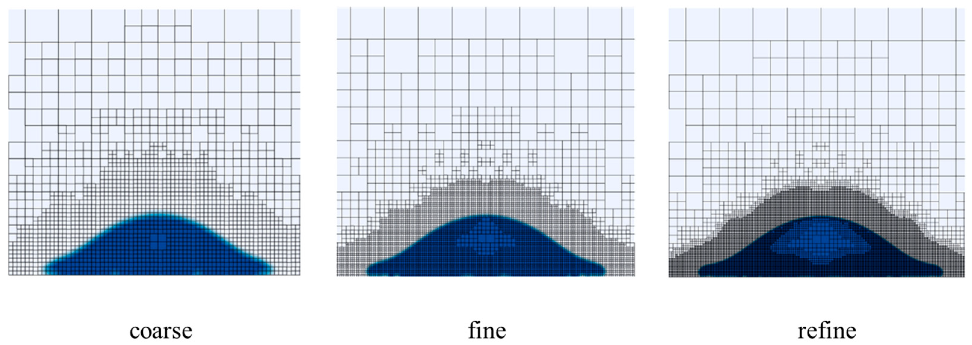
3.1.2. Grid Independence Verification of Motion Model
3.2. Numerical Model Verification
3.2.1. Comparison with Experimental Results
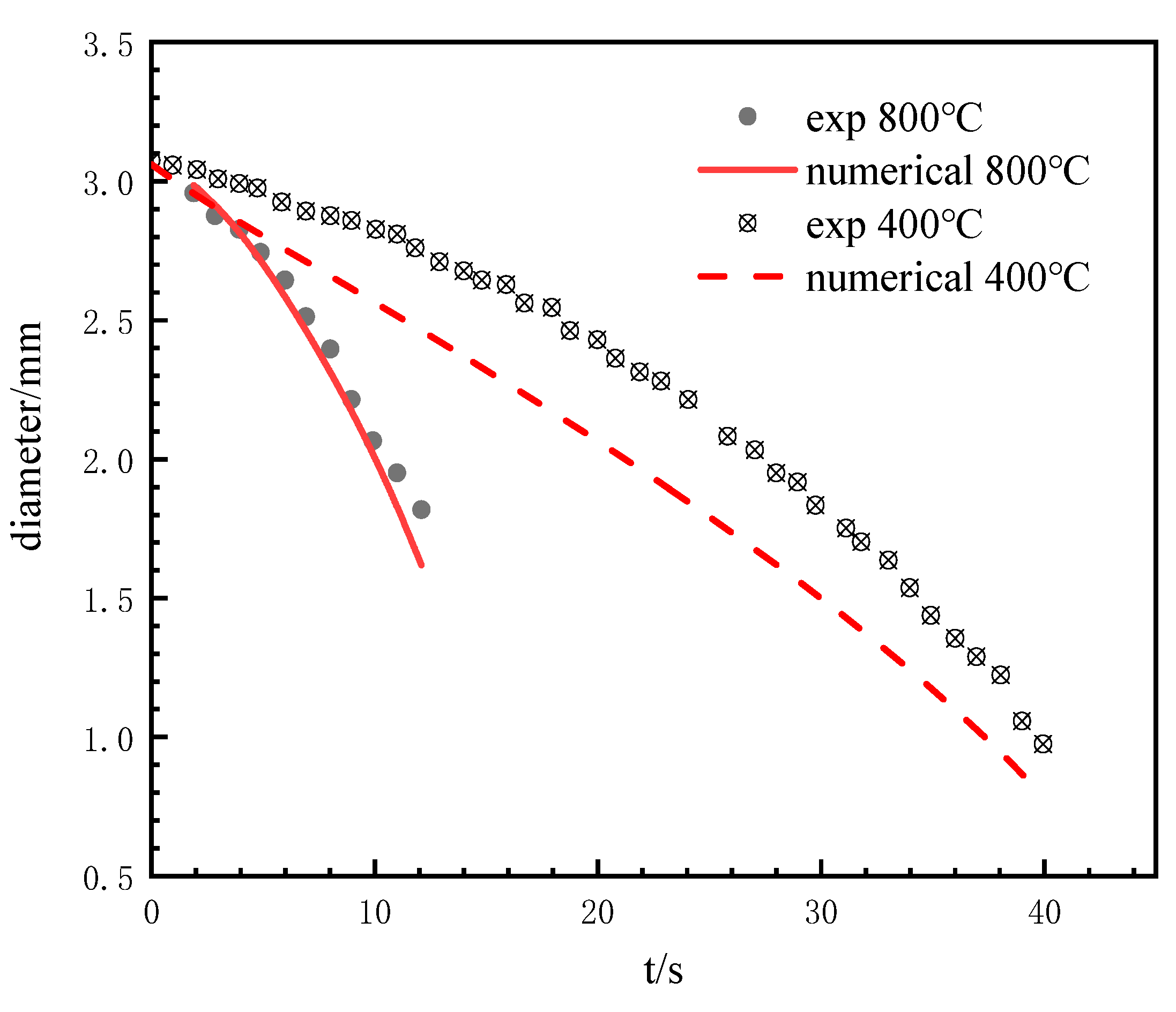
Verification of Phase Transition Model
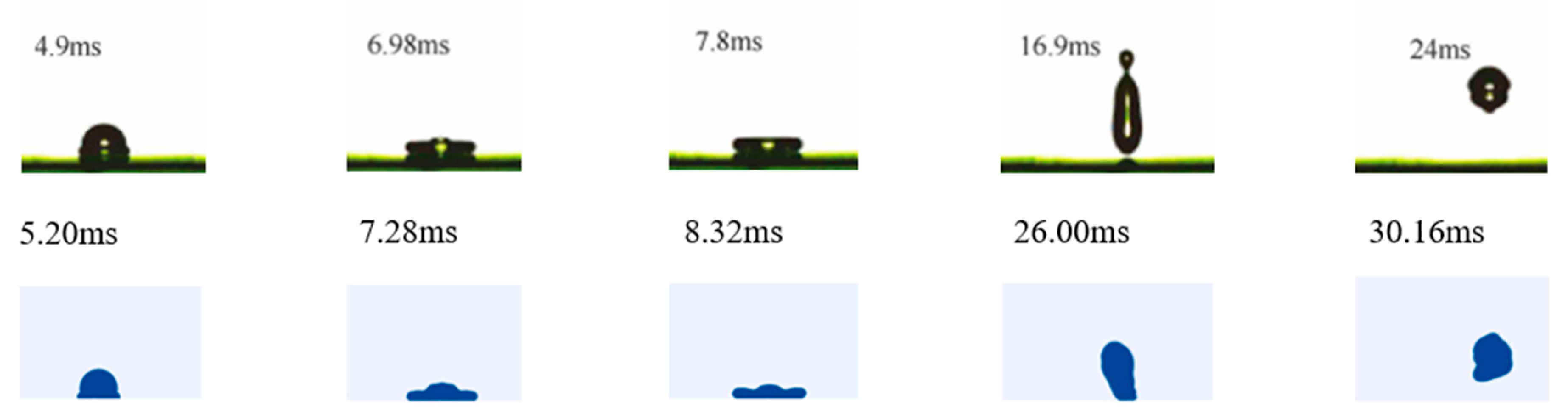
Verification of Motion Model
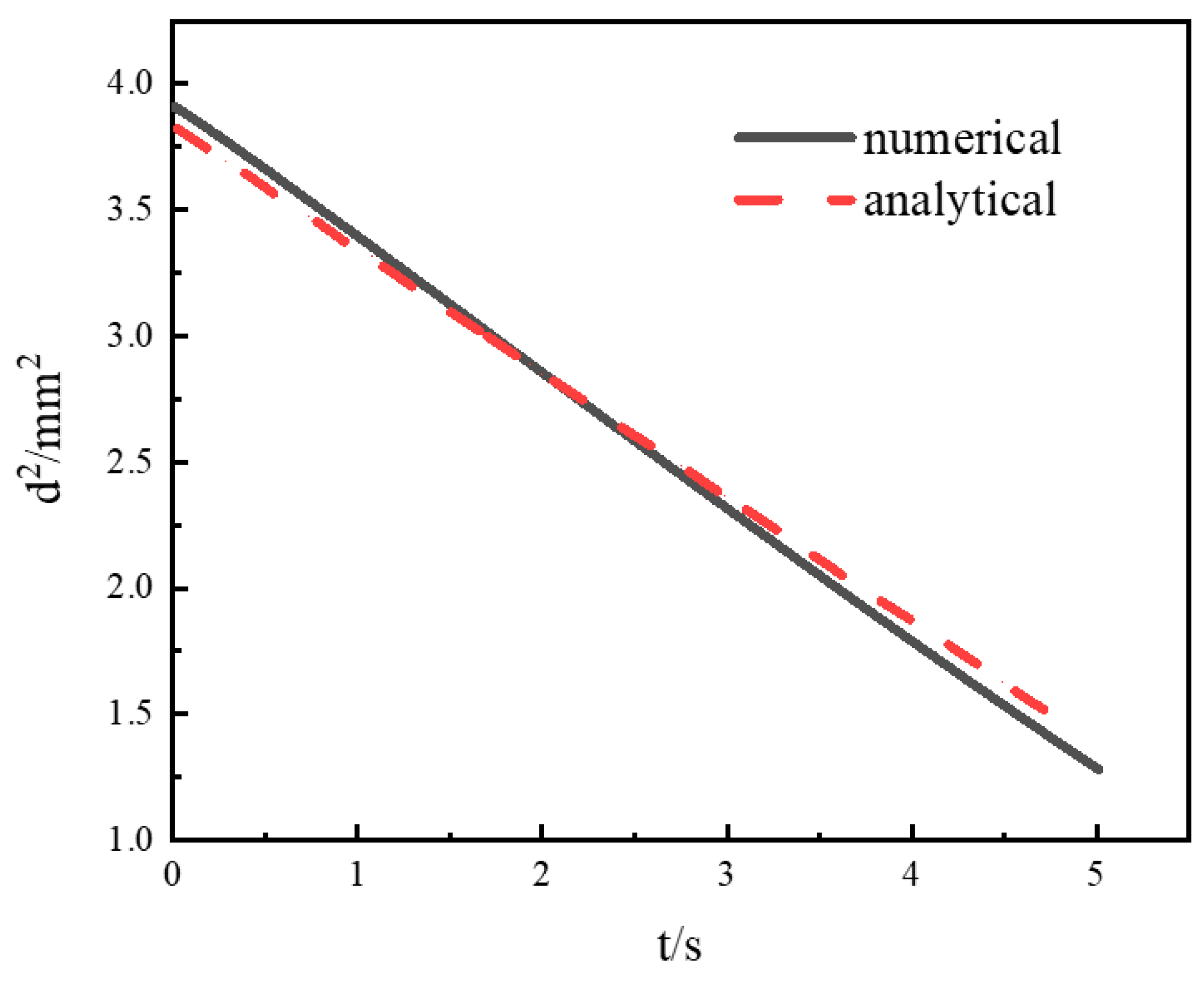
3.2.2. Comparison with Analytical Results
4. Results and Discussion
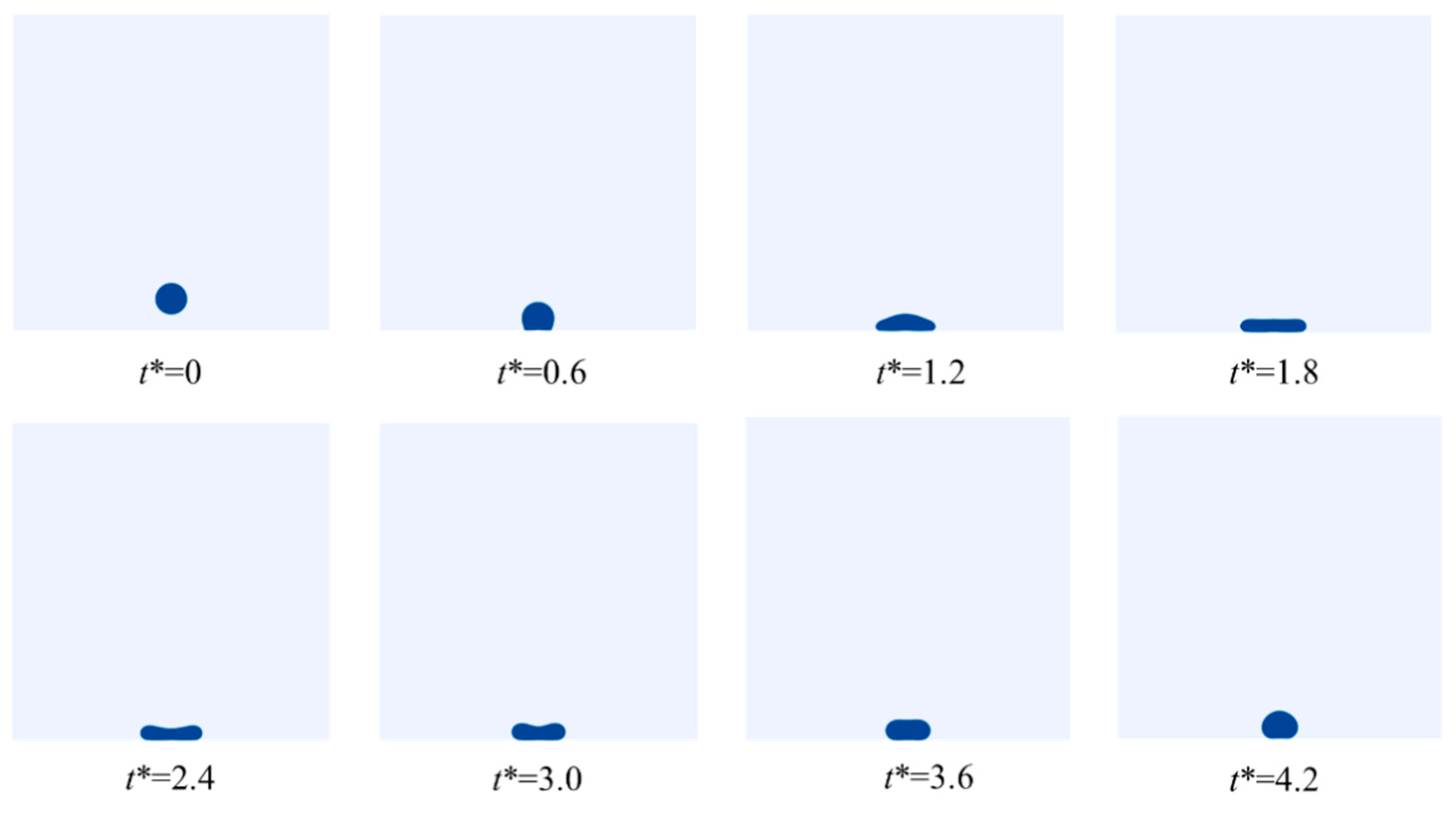
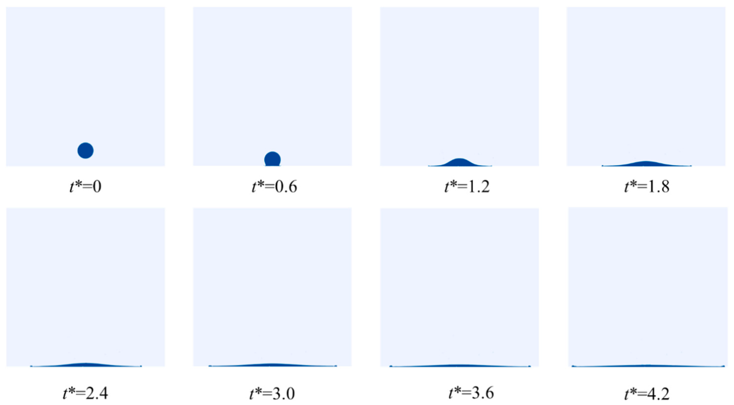
4.1. LN2 Droplet Spreading Process
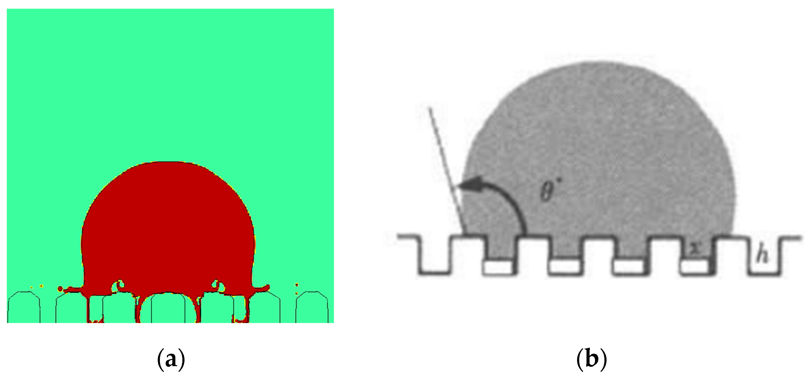
4.1.1. Effect of the Micro-Structured Surface
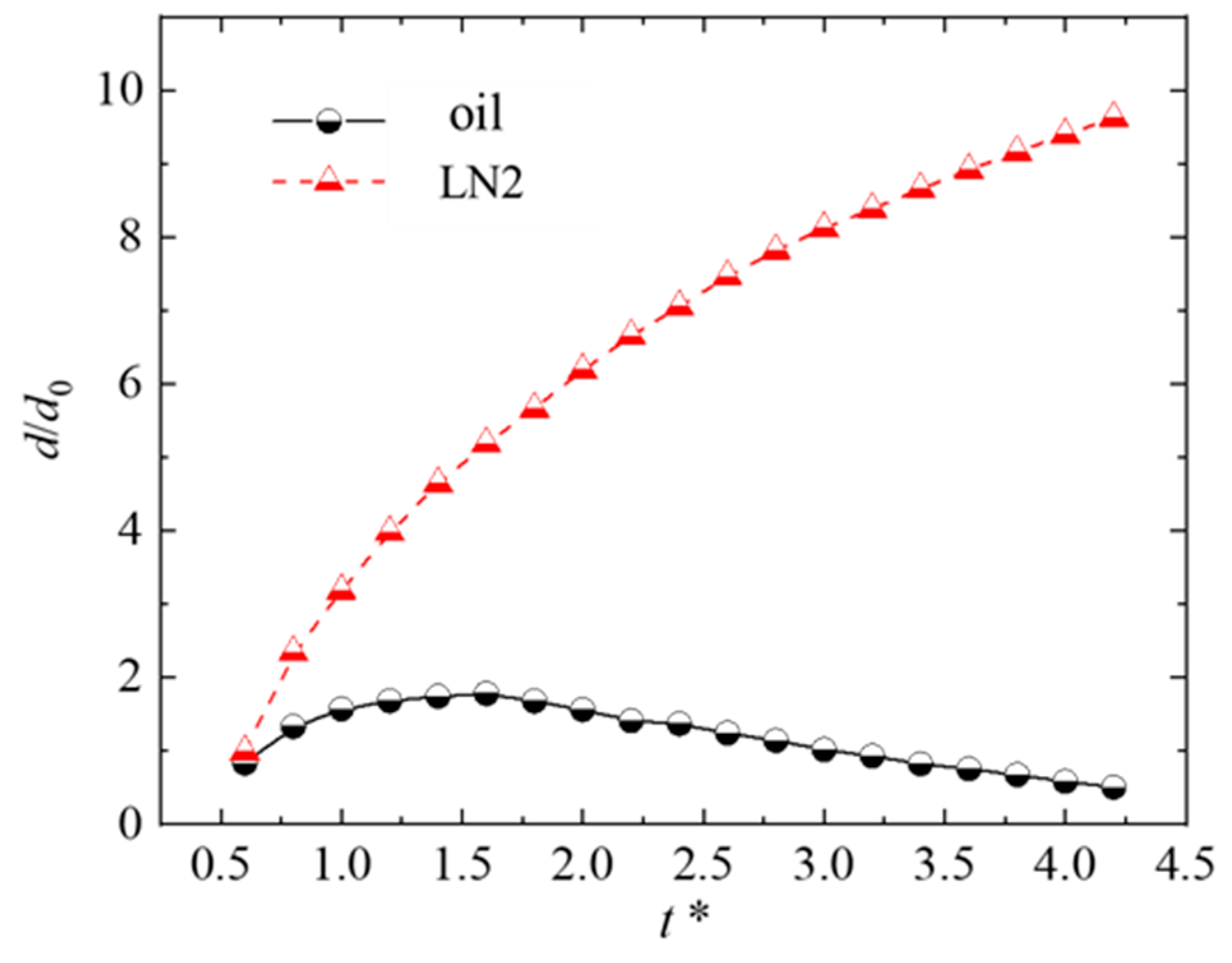
4.1.2. Effect of the Thermophysical Properties
4.2. LN2 Droplet Vaporization Process
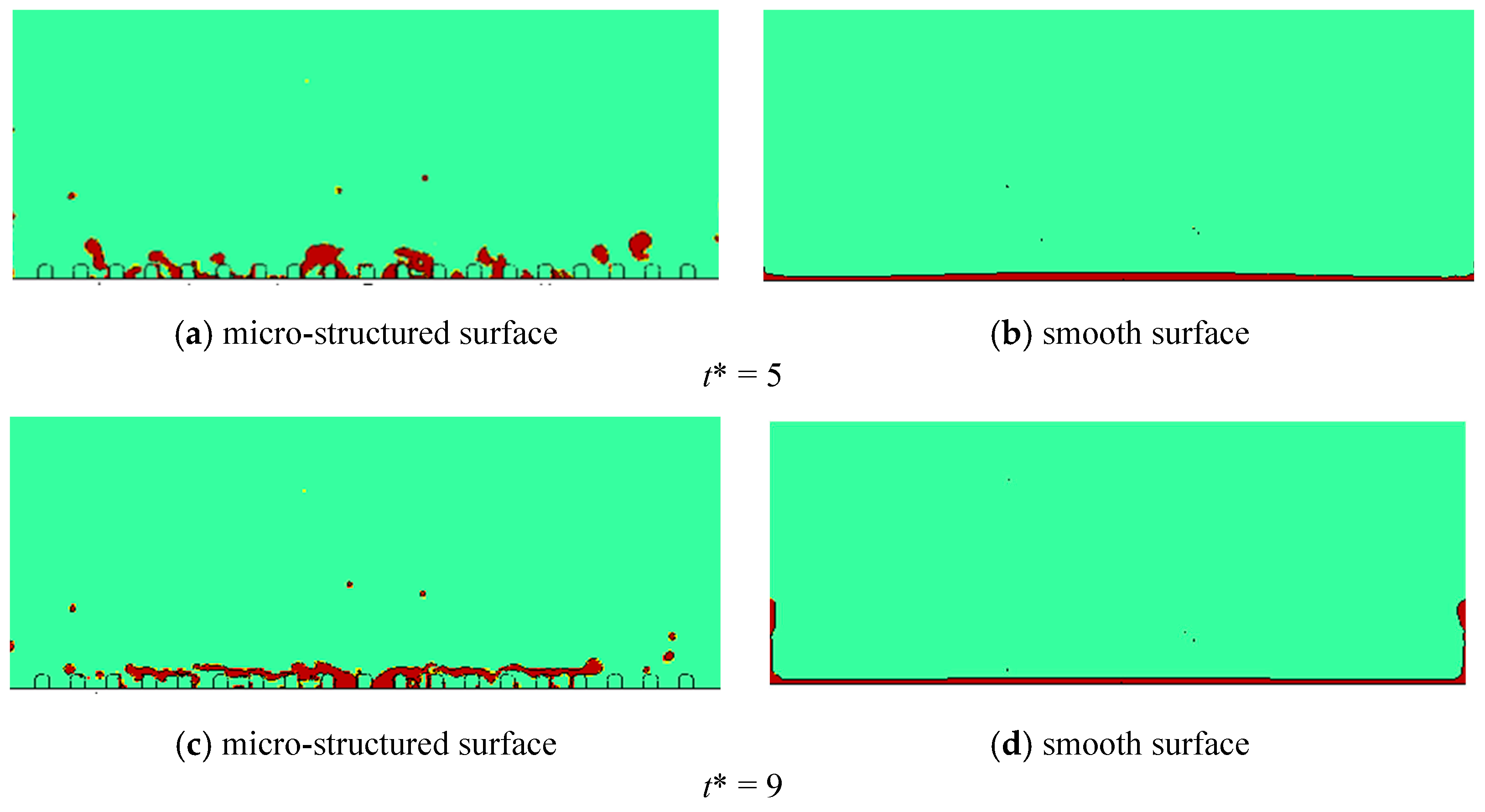
4.2.1. Effect of the Micro-Structured Surface
4.2.2. Effect of Weber Number
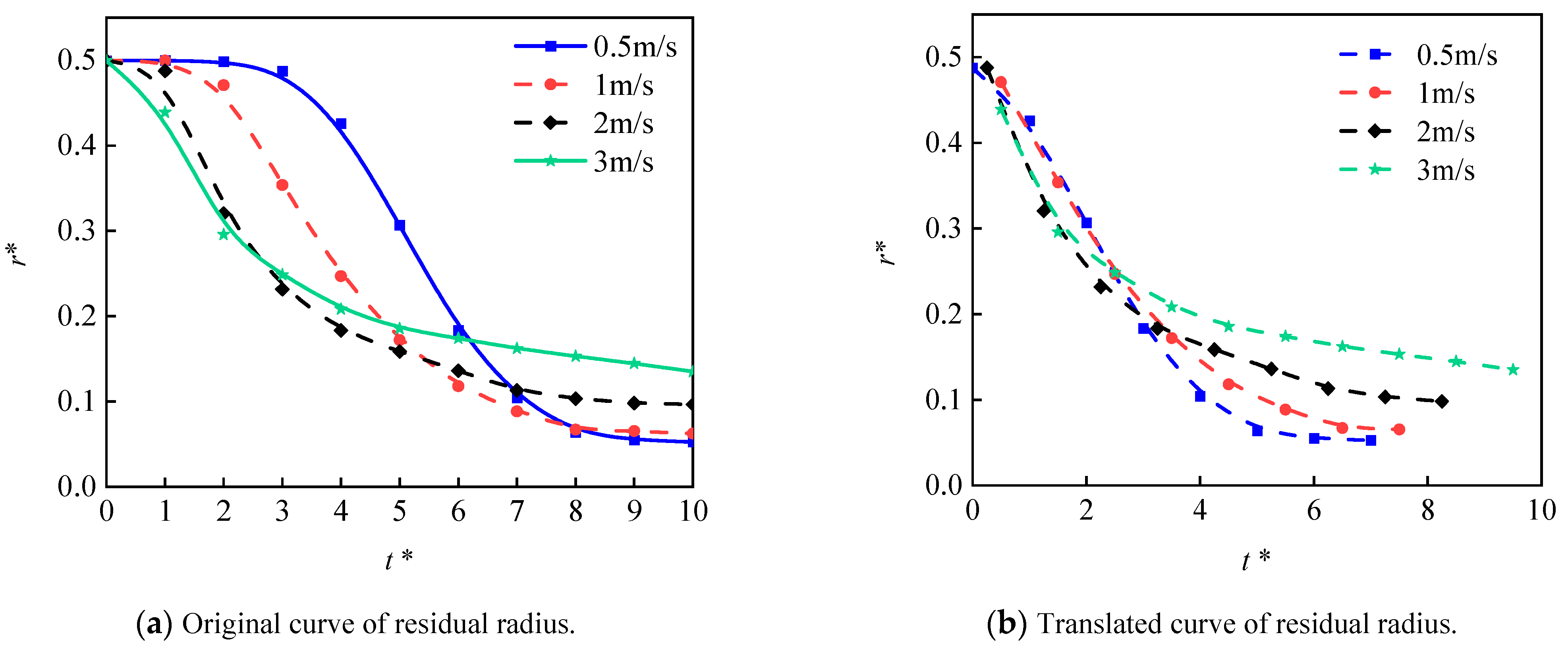
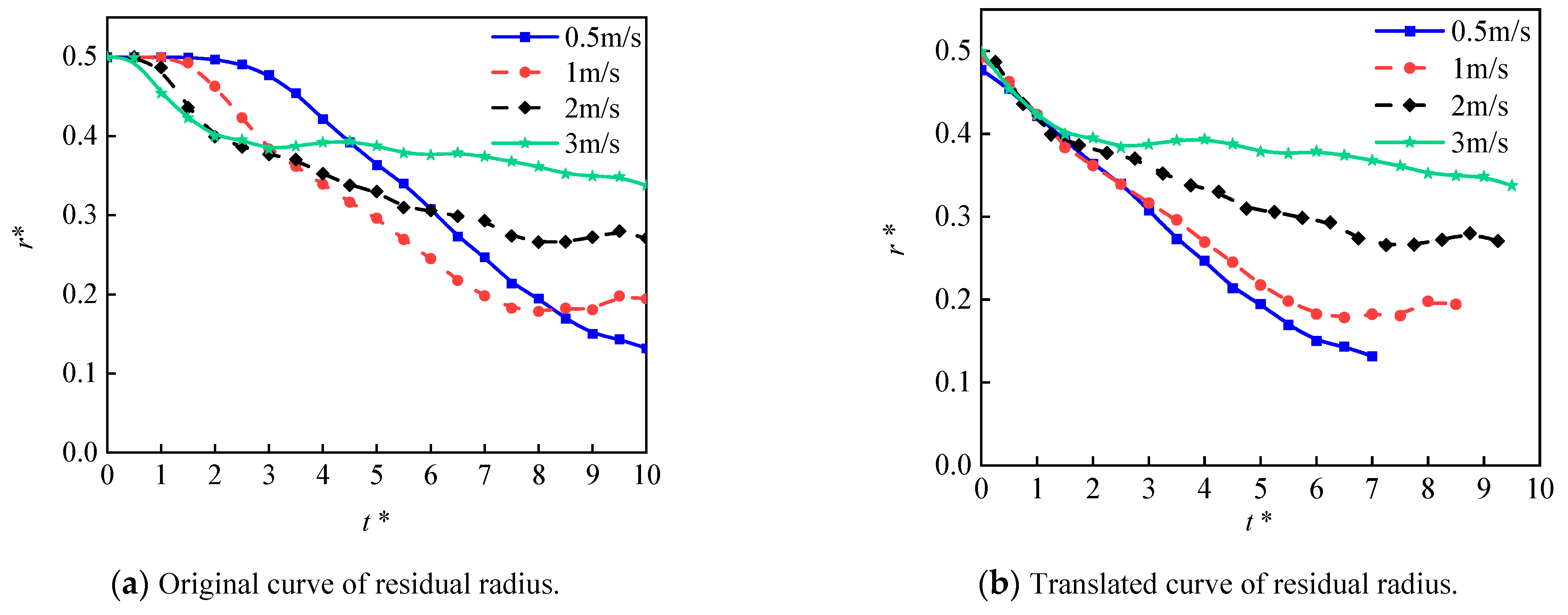
4.2.3. Effects of Impinging Velocity
5. Conclusions
- (1)
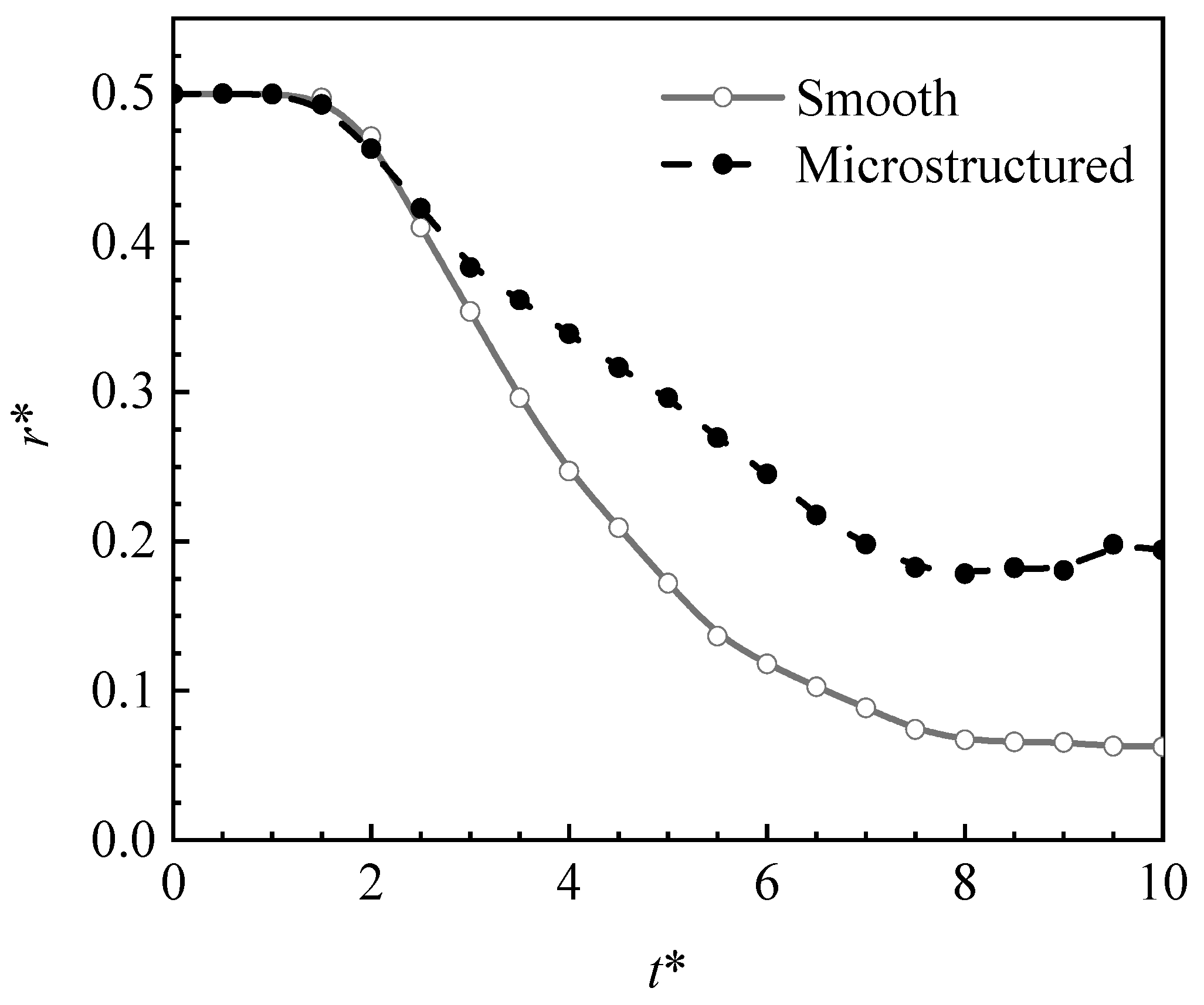
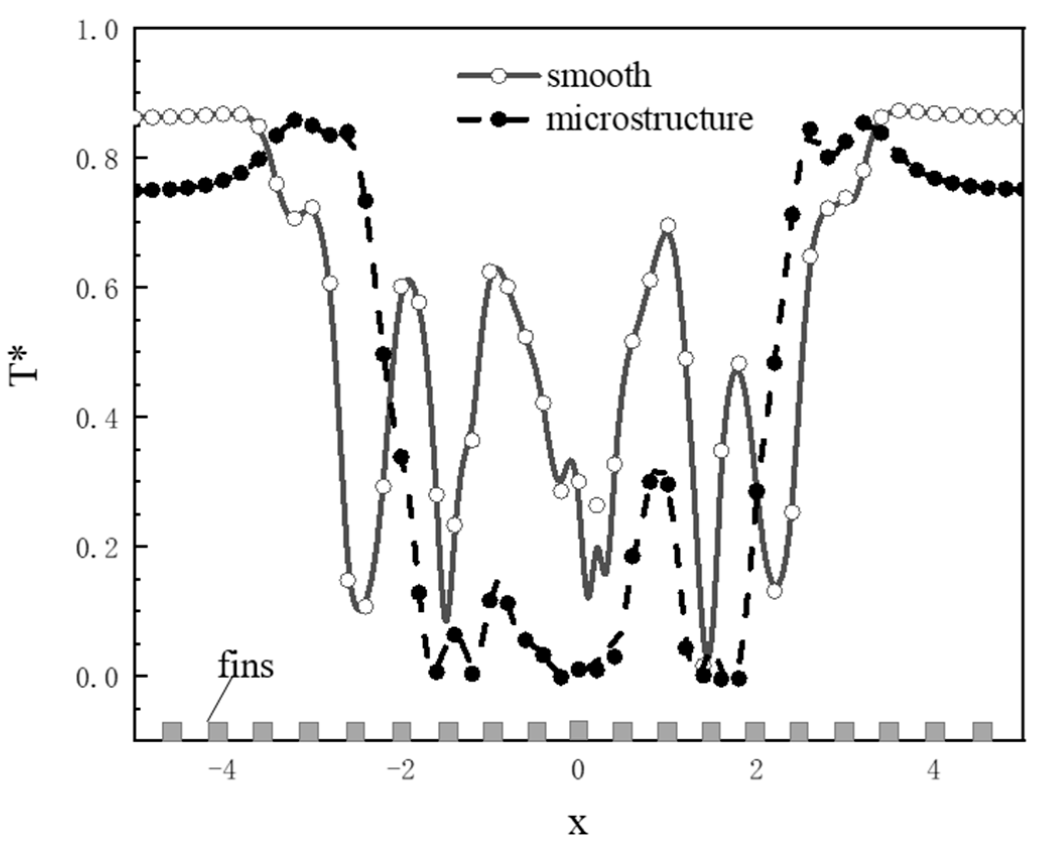
- The Leidenfrost phenomenon occurs on both surfaces, namely micro-structured and smooth surfaces owing to a large temperature difference. The produced vapor layer hindered the heat transfer between the hot surfaces and the LN2 droplet. The droplet cannot completely wet the micro-structured surface, resulting in a small spreading diameter in the counterpart of the droplet at the smooth surface. The slow vaporization process is observed at the micro-structured surface rather than that of the smooth surface.
- (2)
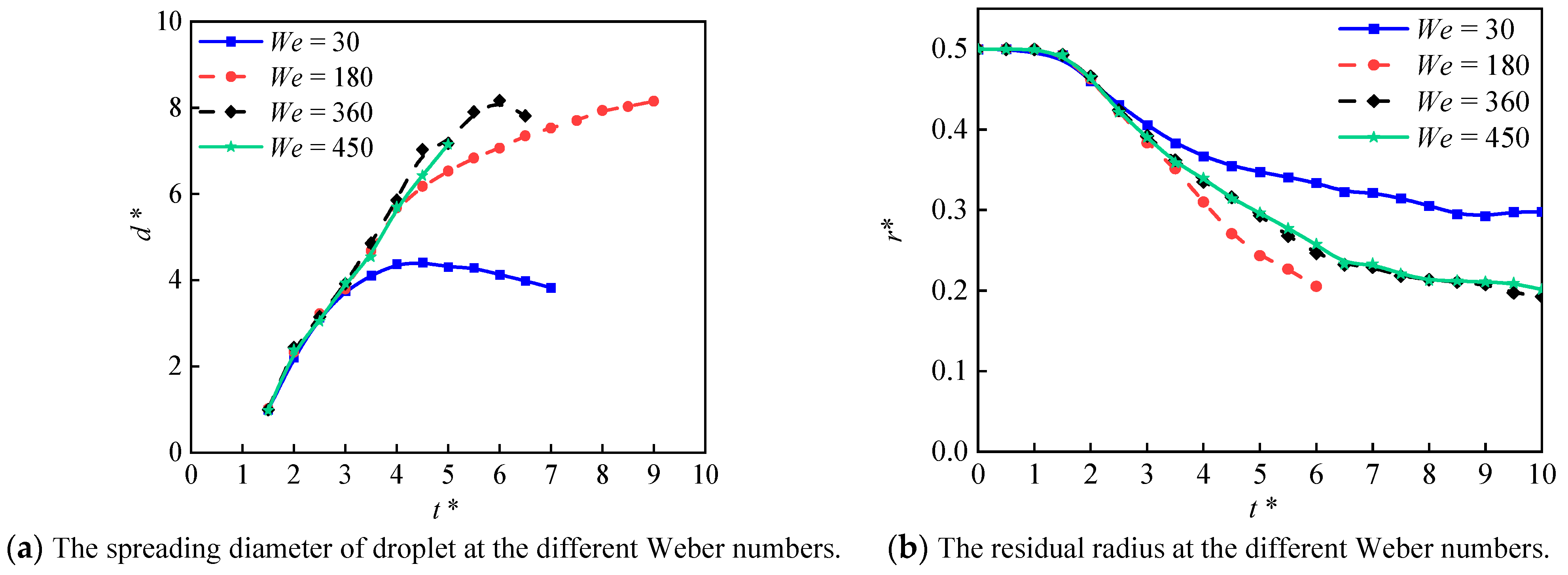
- The Weber number affects the heat transfer of liquid nitrogen droplets on both smooth and micro-structured surfaces. On the smooth surface, the Weber number greater than 180 showed a minor effect on the droplet’s spreading morphology, and no obvious effect was observed at the vaporization rate. On the other hand, the micro-structured surface exhibited the highest vaporization rate at the Weber number of 180.
- (3)
- Impinging velocity showed a noticeable impact on the heat transfer behavior. At the micro-structured surface, a large impinging velocity can lead to severe crushing and splashing of the droplet. The secondary droplet rolls over on the micro-structured surface, and the heat transfer performance becomes worse than that of the smooth surface.
Author Contributions
Funding
Data Availability Statement
Acknowledgments
Conflicts of Interest
Nomenclature
| d | Diatemer, [mm] | ρ | Density, [kg/m3] |
| H | Height of the droplet, [mm] | λ | Thermal conductivity, [W/(m·K)] |
| T | Temperature, [K] | μ | Viscosity, [Pa·s] |
| u | Velocity of the droplet, [m/s] | σ | Surface tension coefficient |
| a | Thickness of the fins, [mm] | Φ | Heat source term |
| b | Spacing of the fins, [mm] | κ | Surface curvature |
| h | Height of the fins, [mm] | δs | Dirac-delta function |
| T | Time, [s] | τc | Control time |
| f | Volume of liquid phase | ||
| p | Pressure, [Pa] | Subscripts | |
| D | Deformation rate tensor | l | Liquid |
| cp | Specific heat, [kJ/(kg·K)] | g | Gas |
| m | Mass flux | * | Dimensionless parameter |
| q | Heat flux | v | Velocity |
| n | Normal vector | 0 | Initial parameter |
| hlg | Heat of vapor, [kJ/kg] | ||
| Interface displacement velocity, [m/s] | Abbreviations | ||
| r | Radius, [mm] | Re | Reynolds number |
| K | Constant | We | Weber number |
| x,y | Dimentionless cartesian coordinate | LN2 | Liquid nitrogen |
| DNS | Direct numerical simulation | ||
| Greek symbols | VOF | Volume of fluid | |
| α | Thermal diffusivity, [m2/s] | Pe | Peclet number |
References
- Somasundaram, S.; Tay, A.A.O. A study of intermittent liquid nitrogen sprays. Appl. Therm. Eng. 2014, 69, 199–207. [Google Scholar] [CrossRef]
- Fan, Y.F.; Gong, L.H.; Xu, X.D.; Li, L.F.; Zhang, L.; Xiao, L.Y. Cryogenic system with the sub-cooled liquid nitrogen for cooling HTS power cable. Cryogenics 2005, 45, 272–276. [Google Scholar] [CrossRef]
- Willert, C.; Stockhausen, G.; Beversdorff, M.; Klinner, J.; Lempereur, C.; Barricau, P.; Quest, J.; Jansen, U. Application of Doppler global velocimetry in cryogenic wind tunnels. Exp. Fluids 2005, 2, 420–430. [Google Scholar] [CrossRef]
- Gosain, S.; Mercer, K.; Twaddell, W. Liquid nitrogen spray cryotherapy in Barrett’s esophagus with high-grade dysplasia: Long-term results. Gastrointest. Endosc. 2013, 2, 260–265. [Google Scholar] [CrossRef] [PubMed]
- James, C.; Purnell, G.; James, S.J. A Review of Novel and Innovative Food Freezing Technologies. Food Bioprocess Technol. 2015, 8, 1616–1634. [Google Scholar] [CrossRef]
- Panao, M.R.O.; Guerreiro, J.P.P.V.; Moreira, A.L.N. Microprocessor cooling based on an intermittent multijet spray system. Int. J. Heat Mass Transf. 2012, 55, 2854–2863. [Google Scholar] [CrossRef]
- Wang, C.; Xu, R.; Song, Y.; Jiang, P. Study on water droplet flash vaporization in vacuum spray cooling. Int. J. Heat Mass Transf. 2017, 112, 279–288. [Google Scholar] [CrossRef]
- Yang, Y.; Yang, L.; Du, X.; Yang, Y. Pre-cooling of air by water spray vaporization to improve thermal performance of lithium battery pack. Appl. Therm. Eng. 2019, 163, 114401. [Google Scholar] [CrossRef]
- Liu, X.; Xue, R.; Ruan, Y.; Chen, L.; Zhang, X.; Hou, Y. Effects of injection pressure difference on droplet size distribution and spray cone angle in spray cooling of liquid nitrogen. Cryogenics 2017, 83, 57–63. [Google Scholar] [CrossRef]
- Xue, R.; Ruan, Y.; Liu, X.; Zhong, X.; Chen, L.; Hou, Y. Internal and external flow characteristics of multi-nozzle spray with liquid nitrogen. Cryogenics 2021, 114, 103255. [Google Scholar] [CrossRef]
- Wang, Y.; Dai, M.; Liu, K.; Liu, J.; Han, L.; Liu, H. Research on surface heat transfer mechanism of liquid nitrogen jet cooling in cryogenic machining. Appl. Therm. Eng. 2020, 179, 115607. [Google Scholar] [CrossRef]
- Xue, R.; Rang, Y.; Liu, X.; Chen, L.; Liu, L.; Hou, Y. Numerical simulation of liquid nitrogen spray cooling in cryogenic wind tunnel. Cryogenics 2019, 7, 35–40. [Google Scholar]
- Chen, J.; Gao, X.; Bao, S.; Hu, L.; Xie, J. Numerical analysis of spray characteristics with liquid nitrogen. Cryogenics 2020, 109, 103113. [Google Scholar] [CrossRef]
- Wang, C.; Song, Y.; Jiang, P. Modelling of Liquid Nitrogen Spray Cooling in an Electronic Equipment Cabin under Low Pressure. Appl. Therm. Eng. 2018, 136, 319–326. [Google Scholar] [CrossRef]
- Ruan, Y.; Hou, Y.; Xue, R.; Luo, G.; Zhu, K.; Liu, X.; Chen, L. Effects of operational parameters on liquid nitrogen spray cooling. Appl. Therm. Eng. 2019, 146, 85–91. [Google Scholar] [CrossRef]
- Yao, Z.H.; Ruan, Y.; Liu, X.; Zhong, X.; Chen, L.; Hou, Y. Static and dynamic characterization of droplets on hydrophobic surfaces. Chin. Sci. Bull. 2012, 57, 1095–1101. [Google Scholar] [CrossRef] [Green Version]
- Fan, Y.L.; Hao, P.; Zhang, X.; He, F. Retraction dynamics of a water droplet impacting onto a microgrooved hydrophobic surface at different velocities and surface temperatures. Int. J. Heat Mass Transf. 2021, 168, 120851. [Google Scholar] [CrossRef]
- Qin, Y.; Guo, Q.; Chen, R.; Zhang, Y.; Wang, Y. Numerical investigation of water droplet impact on PEM fuel cell flow channel surface. Renew. Energy 2020, 168, 750–763. [Google Scholar] [CrossRef]
- Zhan, Y.; Sun, G.; Okawa, T.; Aoyagi, M.; Takata, T. Droplet generation during spray impact onto a downward-facing solid surface. Exp. Therm. Fluid Sci. 2021, 126, 110402. [Google Scholar] [CrossRef]
- Wang, H.; Luo, K.; Hawkes, E.R.; Chen, J.H.; Fan, J. Turbulence, vaporization and combustion interactions in n -heptane droplets under high pressure conditions using DNS. Combust. Flame 2021, 225, 417–427. [Google Scholar] [CrossRef]
- Dodd, M.S.; Mohaddes, D.; Ferrante, A.; Ihme, M. Analysis of droplet vaporization in isotropic turbulence through droplet-resolved DNS. Int. J. Heat Mass Transf. 2021, 172, 121157. [Google Scholar] [CrossRef]
- Lupo, G.; Gruber, A.; Brandt, L.; Duwig, C. Direct numerical simulation of spray droplet vaporization in hot turbulent channel flow. Int. J. Heat Mass Transf. 2020, 160, 120184. [Google Scholar] [CrossRef]
- Wang, J.; Barba, F.D.; Picano, F. Direct numerical simulation of an evaporating turbulent diluted jet-spray at moderate Reynolds number. Int. J. Multiph. Flow 2021, 137, 103567. [Google Scholar] [CrossRef]
- Popinet, S. Gerris: A tree-based adaptive solver for the incompressible Euler equations in complex geometries. J. Comput. Phys. 2003, 190, 572–600. [Google Scholar] [CrossRef] [Green Version]
- Basilisk Home Page. Available online: http://www.basilisk.dalembert.upmc.fr (accessed on 18 November 2005).
- Volkov, R.S.; Strizhak, P.A. Planar laser-induced fluorescence diagnostics of water droplets heating and vaporization at high-temperature. Appl. Therm. Eng. 2017, 127, 141–156. [Google Scholar] [CrossRef]
- Ling, C.; Wang, H.; Zhu, X.; Chen, R.; Ding, Y.; Liao, Q. Numerical simulation of droplet imapct on surfaces with different wettabilities. J. Chem. Eng. 2013, 64, 2745–2751. [Google Scholar]
- Hatta, N.; Fujimoto, H.; Kinoshita, K.; Takuda, H. Experimental Study of Deformation Mechanism of a Water Droplet Impinging on Hot Metallic Surfaces Above the Leidenfrost Temperature. J. Fluids Eng. 1997, 119, 692–699. [Google Scholar] [CrossRef]
- Andrade, R.; Skurtys, O.; Osorio, F. Experimental study of drop impacts and spreading on epicarps: Effect of fluid properties. J. Food Eng. 2012, 109, 430–437. [Google Scholar] [CrossRef]
- Escure, C.; Vardelle, M.; Fauchais, P. Experimental and Theoretical Study of the Impact of Alumina Droplets on Cold and Hot Substrates. Plasma Chem. Plasma Process. 2003, 23, 185–221. [Google Scholar] [CrossRef]
- Cassie, A.; Baxter, S. Wettability of porous surfaces. Trans. Faraday Soc. 1944, 40, 546–551. [Google Scholar] [CrossRef]


| 77 K | μ | cp | σ | α | hlg | |
|---|---|---|---|---|---|---|
| LN2 | 807.69 | 162.94 | 2.0398 | 8.9601 | 0.000883 | 199.63 |
| N2 | 4.4367 | 5.4154 | 1.1214 | / | 0.014363 | / |
| 300 K | cp | α | ||
|---|---|---|---|---|
| copper | 8930 | 386 | 398 | 0.000115 |
Publisher’s Note: MDPI stays neutral with regard to jurisdictional claims in published maps and institutional affiliations. |
© 2022 by the authors. Licensee MDPI, Basel, Switzerland. This article is an open access article distributed under the terms and conditions of the Creative Commons Attribution (CC BY) license (https://creativecommons.org/licenses/by/4.0/).
Share and Cite
Wang, L.; Ding, Y.; Qiu, Y.; Yu, Y.; Xie, J.; Chen, J. Numerical Study on Spreading and Vaporization Process of Liquid Nitrogen Droplet Impinging on Heated Wall. Energies 2022, 15, 8700. https://doi.org/10.3390/en15228700
Wang L, Ding Y, Qiu Y, Yu Y, Xie J, Chen J. Numerical Study on Spreading and Vaporization Process of Liquid Nitrogen Droplet Impinging on Heated Wall. Energies. 2022; 15(22):8700. https://doi.org/10.3390/en15228700
Chicago/Turabian StyleWang, Liu, Yue Ding, Yinan Qiu, Yunxing Yu, Junlong Xie, and Jianye Chen. 2022. "Numerical Study on Spreading and Vaporization Process of Liquid Nitrogen Droplet Impinging on Heated Wall" Energies 15, no. 22: 8700. https://doi.org/10.3390/en15228700
APA StyleWang, L., Ding, Y., Qiu, Y., Yu, Y., Xie, J., & Chen, J. (2022). Numerical Study on Spreading and Vaporization Process of Liquid Nitrogen Droplet Impinging on Heated Wall. Energies, 15(22), 8700. https://doi.org/10.3390/en15228700