Article

Multi-Parameter Optimization of Heat Dissipation Structure of Double Disk Magnetic Coupler Based on Orthogonal Experimental Design

1
State Key Laboratory of Mining Response and Disaster Prevention and Control in Deep Coal Mines, Anhui University of Science and Technology, Huainan 232001, China
2
College of Mechanical Engineering, Anhui University of Science and Technology, Huainan 232001, China
*
Author to whom correspondence should be addressed.
Energies 2022, 15(23), 8801; https://doi.org/10.3390/en15238801
Submission received: 18 October 2022 / Revised: 17 November 2022 / Accepted: 21 November 2022 / Published: 22 November 2022
(This article belongs to the Section J1: Heat and Mass Transfer)

Abstract

:
The existing heat dissipation research on double disk magnetic couplers ignores the coupling influence of electromagnetic temperature–stress and other multiphysics fields, and the error between the calculation and analysis results and the measured values is large. Therefore, a multi-parameter optimization method for heat dissipation structures of double disk magnetic couplers based on orthogonal experimental design is proposed. Based on the double disk magnetic coupler model, a three-dimensional finite element model based on fluid–solid–heat coupling is established, with the axial air gap length, input motor speed, the thickness of the permanent magnet in the magnetizing direction, the thickness of the copper plate, the number of fins of the heat dissipation plate and the length of the fins of the heat dissipation plate as design variables. Six-factor and three-level simulation experiments are designed with the minimum temperature of the heat dissipation plate as the objective function, and additionally, orthogonal experiments were designed according to the actual working conditions by selecting the optimal combination of parameters and modifying the model to perform physical tests. The results show that the variables that have the most significant impact on heat dissipation performance from high to low are as follows: axial air gap length, input motor speed, the length of the fins of the heat dissipation plate, the thickness of the permanent magnet in the magnetizing direction, the number of fins of the heat dissipation plate and the thickness of the copper plate. The increase in axial air gap length can effectively reduce the temperature rise, and the maximum decrease can reach 9.76%. Under the same conditions, the input motor speeds are set to 300 r/min, 400 r/min, 500 r/min, 600 r/min and 700 r/min, respectively, and the simulation results are in good agreement with the physical test results, with a maximum error of 4.8%. The error between the simulation result and the physical test result is only 1.9% under the optimal combination of parameters obtained by the orthogonal experiment, which verifies the correctness of the optimization model. In conclusion, the study is of reference significance for the parameter optimization of the heat dissipation structure of the double disk magnetic coupler.

1. Introduction

Double disk magnetic couplers, a revolutionary energy-saving transmission device, boast the advantages of high efficiency speed regulation, strong adaptability and low running costs. They have become one of the key research objects of magnetic transmission systems in recent years [1,2]. During the operation of the coupler, the magnetic induction eddy current loss will generate a significant amount of heat, leading to an increase in the temperature of all parts of the transmission system. Too high a temperature will affect the working characteristics of permanent magnet materials [3,4], which in turn affects the reliability of the transmission system. Electromagnetic temperature–stress coupling energy is a rather complicated problem, which has become one of the hot topics in the field of magnetic coupling [5].
As far as international studies are concerned, R Bujakiewicz-korońska and J Koroński carried out a study on the principle of minimum entropy production for diffusion and heat transfer in an open system, deriving general formulas and typical values of the entropy production for diffusion and heat transfer for any substance that involves specific boundary conditions [6]; Andrew T. Morrision et al. explored the temperature field of a heat sink in a natural convection state by using finite element software, and calculated the thermodynamic parameters of heat sink fins in a thermal steady state using an iterative method [7]; Fabrizio Madgnetti et al. performed finite element analysis by means of a dynamic coupling method of temperature and fluid, which provided guidance for the temperature rise characteristics of a disk magnetic coupler [8]. A study was also carried out by Avram Bar-cohen in which the analytical formula of the Nusselt number was applied to design the size of a heat sink and derive the optimal size based on the “least material” theory by taking the total heat dissipation and space heat transfer coefficient of the device as the objective function [9]. As far as domestic studies are concerned, Yang Chaojun simulated and analyzed the mechanical characteristics and speed-regulating characteristics of a speed-regulating magnetic coupler by using the finite element method, contributing to a better realization of the speed regulation function for the coupler [10]; Wang Lei et al. further put forward a method to calculate the heat dissipation coefficient based on the fluid–solid coupling velocity field and then analyzed the coupler temperature field, demonstrating the applicability of the coupler temperature field distribution to the heat dissipation surfaces of different couplers [11]; GE Yanjun et al. designed a magnetic coupler with the outer rotor being a permanent magnet rotor and the inner rotor being a copper sleeve rotor, and verified the heat dissipation effect of the heat dissipation structure on the magnetic coupler by simulation analysis [12]. To sum up, a plurality of studies on magnetic couplers have been carried out at home and abroad, but none of these studies have employed the fluid-solid–heat coupling analysis method to optimize the multi-parameters for the heat dissipation problem of the double disk magnetic coupler. Its structural parameters, the size of the copper plate, the air gap of the permanent magnet disk, the input speed of the motor and the load are the key factors that affect the heat dissipation performance.
The existing heat dissipation research on double disk magnetic couplers ignores the coupling influence of electromagnetic temperature–stress and other multiphysics fields, and the error between the simulation calculation and analysis results and the measured values is large. Therefore, this paper builds a finite element simulation platform for permanent magnetic field–temperature field coupling based on the thermodynamic model for the heat dissipation structure parameters of the double disk magnetic coupler. Taking the minimum temperature of the heat dissipation plate as the objective function and the mass change and average output speed as the constraint function, an orthogonal experimental method was used to optimize the heat dissipation structure with multi-parameters to obtain the optimal structure layout and parameters. Under the optimal parameter combination conditions, physical experiments are carried out for verification.

2. Structure and Working Principle of Double Disk Magnetic Coupler

2.1. Structure

The double disk magnetic coupler is mainly composed of an input shaft, heat dissipation plate, conductor yoke, copper plate, permanent magnet plate, permanent magnet yoke, gap-adjusting device and output shaft. Considering the symmetry of the left and right sides of the double disk magnetic coupler, only the left side structural model is analyzed in this paper. Specifically, the input shaft is connected to the input motor, and a large amount of heat is generated by the magnetic induction eddy current loss, which is dissipated by the annular fins (fixed on the left side of the conductor yoke) on the radiating plate. The conductor yoke can not only fix the copper plate, but also guide the magnetic lines generated by the permanent magnets, so that more magnetic lines enter the copper plate to improve the transmission efficiency, increase the local magnetic induction intensity, and prevent or reduce the magnetic flux leakage between the permanent magnets [13]. The copper plate is fixed on the right side of the conductor yoke by hexagon bolts. The distance between the copper plate and the permanent magnet disk is equal, with air as the gas medium. The permanent magnet disk is composed of a permanent magnet, an aluminum disk and a flange, where the aluminum disk is fixed on the permanent magnet yoke. The permanent magnet yoke is fixed on the right side of the permanent magnet disk, which plays a role in controlling the magnetic flux direction and increasing the magnetic flux density in the magnetic circuit. The two permanent magnet disks are connected by a gap-adjusting device and are symmetrically distributed. The conductor yoke is connected to the output shaft, as shown in Figure 1.

2.2. Working Principle

When the input motor is energized, the input shaft drives the copper plate on the right side of the conductor yoke to rotate, and the copper plate and the permanent magnet disk move, resulting in slip. According to Faraday’s electromagnetic induction principle, there is an eddy current between the copper plate and the permanent magnet disk, and the induced magnetic field generated by the eddy current interacts with the magnetic field generated by the permanent magnet to generate torque, which generates heat on the surface of the copper plate. The generated torque drives the permanent magnet disk to rotate in the same direction as the copper plate and drives the output shaft to rotate, thus transmitting power to the load [14].

3. Numerical Calculation Method

3.1. Gas Heat Transfer Control Equation

Fluid–solid–heat coupling calculations are mainly used to solve the problem that gas flow, heat transfer and structural deformation need to be considered at the same time. The key is the heat transfer at the fluid–solid boundary. The heat transfer process can be expressed as follows:
λ ( T n ) = a ( T T f )
where λ is the coefficient of thermal conductivity of the air medium (0.023 W/m·k); T is the temperature detected on the surface of the heat dissipation plate; T n indicates the temperature gradient of the heat dissipation plate in the normal direction of the fluid–solid interface; α is the convective heat transfer coefficient of air; Tf is the temperature of the air.
The heat conduction equation between solids based on the three-dimensional heat conduction differential equation is as follows [15]:
λ 2 T + Φ = 0
where Φ is the heating power of the input motor.
If air is regarded as an incompressible gas, then in the calculation of fluid–solid–heat coupling, the mass conservation equation, momentum conservation equation and energy conservation equation should be taken into account. Its three-dimensional flow and heat transfer control equation is as follows [16]:
v = 0
μ t + ( v ) v = f 1 ρ P + μ 2 v
( ρ T 1 ) t + d i v ( ρ v T 1 ) = d i v ( k c P g r a d T 1 )
where v is the velocity vector; ρ, f, P, μ, cP, T1 and k represent the density, volume force, pressure, dynamic viscosity, specific heat capacity, temperature and thermal conductivity of air, respectively.

3.2. Boundary Parameter Setting

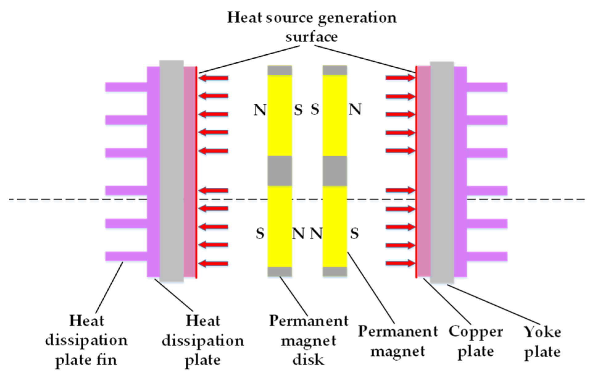
In this paper, the heat dissipation structure of a double disk magnetic coupler is taken as the research object. Figure 2 shows a simplified model of the heat dissipation structure of a double disk magnetic coupler, including a heat source, copper plate, conductor yoke and heat dissipation plate. The end face of the copper plate close to the permanent magnet plate is simplified as a heat source-generating surface, and the heat flow boundary is indicated by an arrow. The conductor yoke is connected to the fins, so that the heat generated on the copper plate can be uniformly and sequentially transmitted to the yoke plate, the heat dissipation plate and the fins of the heat dissipation plate. In this paper, the gas heat transfer control equation is calculated by the steady-state solution [17]. The heat generated by the eddy current loss is transferred from the surface of the copper plate to the surface of the fins of the heat dissipation plate, and finally, the heat is transferred away by the heat exchange between the fin surface and the environment, so as to avoid the accumulation of a large amount of heat on the surface of the copper plate. In addition, all the joints are filled with thermal grease to reduce the contact thermal resistance between components.
Table 1 displays the main dimensional parameters related to the components of the double disk magnetic coupler.
Table 2 displays the material properties of each component.

4. Fluid–Solid–Heat Coupling Finite Element Simulation

In most of the current studies on magnetic couplers, the coupling effects of multiple physical fields, such as temperature field and thermal field, are neglected, resulting in large errors between the calculated analysis results and the measured values. Therefore, in view of the influence of eddy current heat on the temperature of the heat dissipation plate in the three-dimensional magnetic field simulation of a double disk magnetic coupler, a three-dimensional finite element analysis method based on fluid–solid–heat coupling is proposed to calculate the temperature field at the heat sink and solve the temperature of the heat dissipation plate.

4.1. Three-Dimensional Model of Heat Dissipation Structure

The axial air gap length of the double disk magnetic coupler was set to 5 mm, the input motor speed to 400 r/min, the number of heat dissipation plate fins to 6, and the length of the heat dissipation plate fins to 8 mm. Its three-dimensional model is shown in Figure 3.
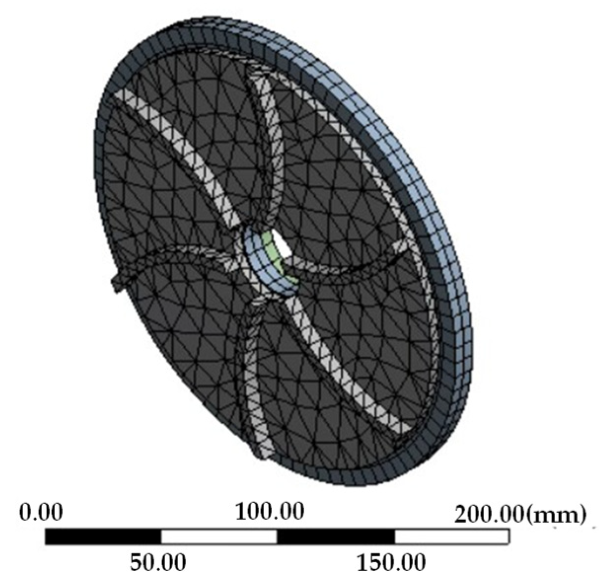
Based on the three-dimensional model of the heat dissipation structure of the double disk magnetic coupler, a steady-state thermal simulation is carried out. The solid domain part and the fluid domain part [18] of the heat dissipation disk are established using a bidirectional coupling solution, in which the solid domain adopts the finite element method and the fluid domain adopts the finite volume method. The rotation domain is selected as the fluid domain, with the speed assigned to 400 r/min, and the grid is set as the MRF model. The meshing is shown in the following Figure 4.
When meshing, the global mesh size is set as 8 mm, the number of nodes is 23,313, the number of meshes is 4929, and the simulation time is 20 s. After grid inspection, it is judged that the grid meets the calculation requirements.

4.2. Permanent Magnetic Field and Temperature Field Coupling Platform

Combining Ansoft Maxwell and Ansys Workbench software, a permanent magnetic field–temperature field coupling platform is built. Considering the symmetry of the left and right sides of the double disk magnetic coupler, only the left side heat transfer model is analyzed in order to simplify the calculation volume. To analyze the effect of eddy current heat on the performance of the copper plates and a permanent magnet, the thermal power generated by the eddy current is introduced into the temperature field of the transient thermal module in turn as the heat source load. The heat generated during the internal heat generation stage is applied to the volume of the copper plate, and the eddy current thermal power on the copper plate is simulated in the magnetic field. Then, the simulation results of the permanent magnetic field are combined with the temperature field, and the temperature of the heat dissipation plate is calculated by simulation. The simulation diagram is shown in Figure 5.
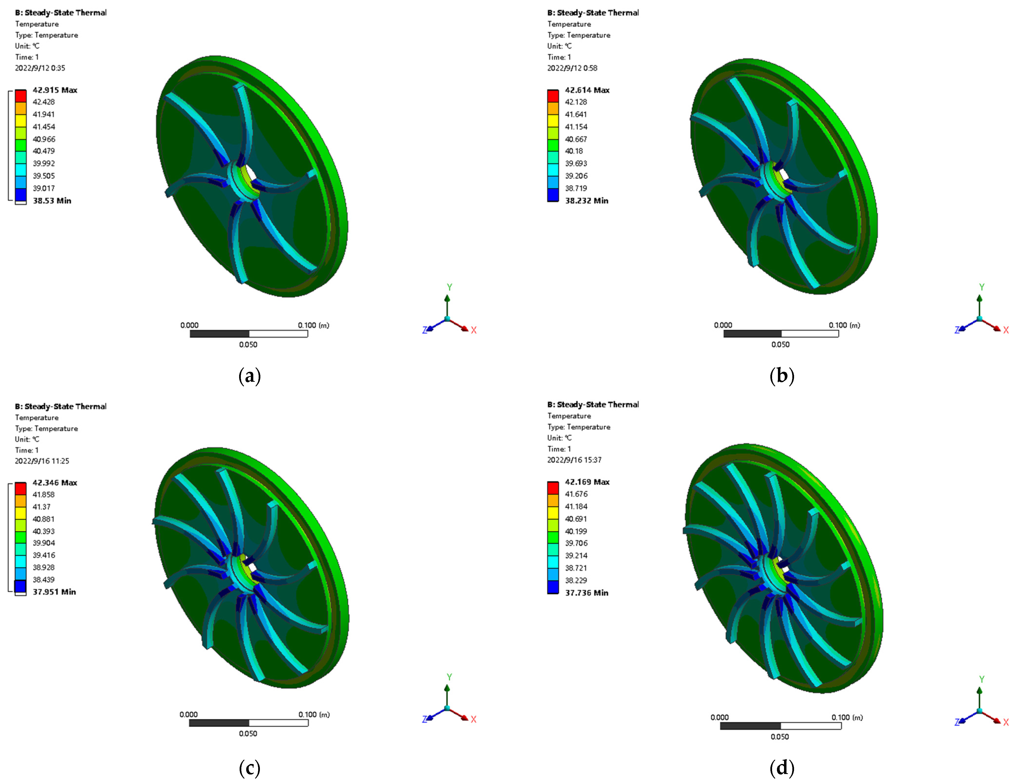
When the ambient temperature is 22 °C, the air gap length is 5 mm, the input motor speed is 400 r/min, and the number of fins of the heat dissipation plate is 6, 8, 10 and 12 in turn, the minimum temperatures are 38.530 °C, 38.232 °C, 37.951 °C and 37.736 °C, respectively, and the maximum temperatures are 42.915 °C and 42.66 °C, respectively. It can be observed that when the number of fins of the heat dissipation plate gradually increases, the temperature range of the heat dissipation plate gradually decreases, and the minimum temperature of the model is concentrated in the center of the fins.

5. Orthogonal Experimental Design

5.1. Structural Parameter Model

In view of the large number of structural parameters of the double disk magnetic coupler, the orthogonal experimental design of the structural parameters of the double disk magnetic coupler is carried out using the software Design Expect 8.0.6. Orthogonal experimental design, compared to other optimization methods, is more widely used by virtue of the fact that it requires fewer combinations of experiments and is generally used for the analysis of the nonlinear influence of factors [19]. In performing this experiment, an appropriate number of highly representative test points are selected from a large number of test points, and a normalized orthogonal table is used to arrange the experiment scientifically. Furthermore, the sensitivity of each factor to the influence of the optimization target is analyzed to seek the optimal structure layout and parameters of the double disk magnetic coupler.
The orthogonal experimental design adopts the three-dimensional magnetic field simulation analysis method to simulate the response value that corresponds to the preselected experimental design point of the temperature of the heat dissipation plate of the double disk magnetic coupler, and the mathematical model is as follows:
{ min T ( x ) g j 0 , j = 1 , 2 , , m x i L x i x i u , i = 1 , 2 , , n
where T is the objective function, gj is the constraint function; the design variable is the analytic function of the objective function and the constraint function, the number of constraint functions is m, x = (x1, x2, … xn) is the design variable, the number of design variables is n, and the upper and lower values of the ith design variable are xiL and xiU, respectively.

5.2. Improved Response Surface Design Principle

Using the improved Box–Behnken (response surface) design principle, the average output speed and the temperature of the heat dissipation plate of the double disk magnetic coupler in the stable operation stage are taken as the response values.
In this paper, a six-factor and three-level simulation experiment is conducted to select sample points in the space composed of six factors. The axial air gap length is taken as 5–15 mm, the input motor speed as 400–800 r/min, the thickness of the permanent magnet in the magnetizing direction as 12.7–16.7 mm, the thickness of the copper plate as 6–10 mm, the number of fins of the heat dissipation plate as 6–10, and the length of the fins of the heat dissipation plate as 8–12 mm. The values of the six factors have not yet been determined, so the axial air gap length, input motor speed, the thickness of the permanent magnet in the magnetizing direction, the thickness of the copper plate, the number of fins of the heat dissipation plate and the length of fins of the heat dissipation plate are selected as the design variables, which are recorded as A, B, C, D, E, and F, respectively. For the convenience of analysis, the dimensionless design variables are converted into dimensionless variables, whose three levels are −1, 0, 1. Dimensional transformation is defined as follows:
x 1 = A 10 5 ; x 2 = B 600 200 ; x 3 = C 14.7 2 ; x 4 = D 8 2 ; x 5 = E 8 2 ; x 6 = F 10 2
The response surface test factors and levels are shown in Table 3 below.

5.3. Orthogonal Experimental Design and Simulation

The experimental software Design Expert 8.0.6 is used to simulate, calculate and obtain the experimental sample data, and the orthogonal experimental simulation results are shown in Table 4.

5.4. Analysis of Variance in Orthogonal Experiment

In order to test whether the established orthogonal experimental model can be further optimized, it is necessary to analyze the variance in the model and confirm the fitting accuracy. Table 5 displays the results of the variance analysis of the orthogonal experimental model of the temperature of the heat dissipation plate.
After calculation, the negative correlation coefficient R2 of the temperature of the heat dissipation plate is 0.9248, which meets the requirements of engineering accuracy.

6. Heat Dissipation Performance Analysis

6.1. Significant Impact

The F-value of the variance analysis of the orthogonal experimental results can be used as a parameter to respond to significant differences. The larger the F-value of the variance analysis, the higher the significant influence [20]. For the six factors, the axial air gap length is 219.53, the input motor speed is 14.29, the thickness of the permanent magnet in the magnetizing direction is 2.95, the thickness of the copper plate is 0.23, the number of fins of the heat dissipation plate is 2.27 and the length of the fins of the heat dissipation plate is 4.55. Therefore, the order of significant influence from high to low is A > B > F > C > E > D. It can be observed that the axial air gap length is the most significant factor affecting the heat dissipation performance, followed by the input motor speed, and its value should be reasonably selected.

6.2. Single Factor Analysis

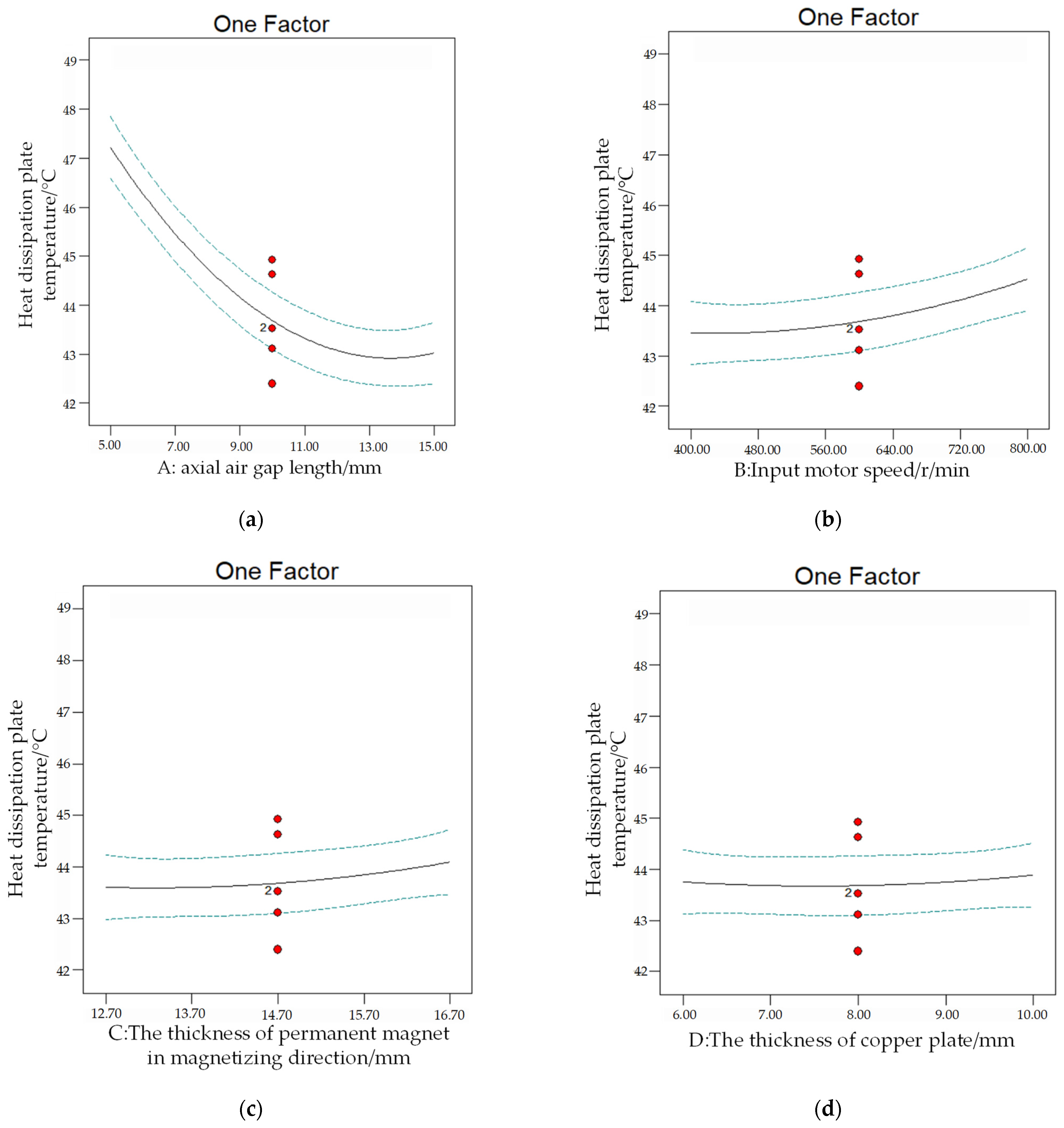
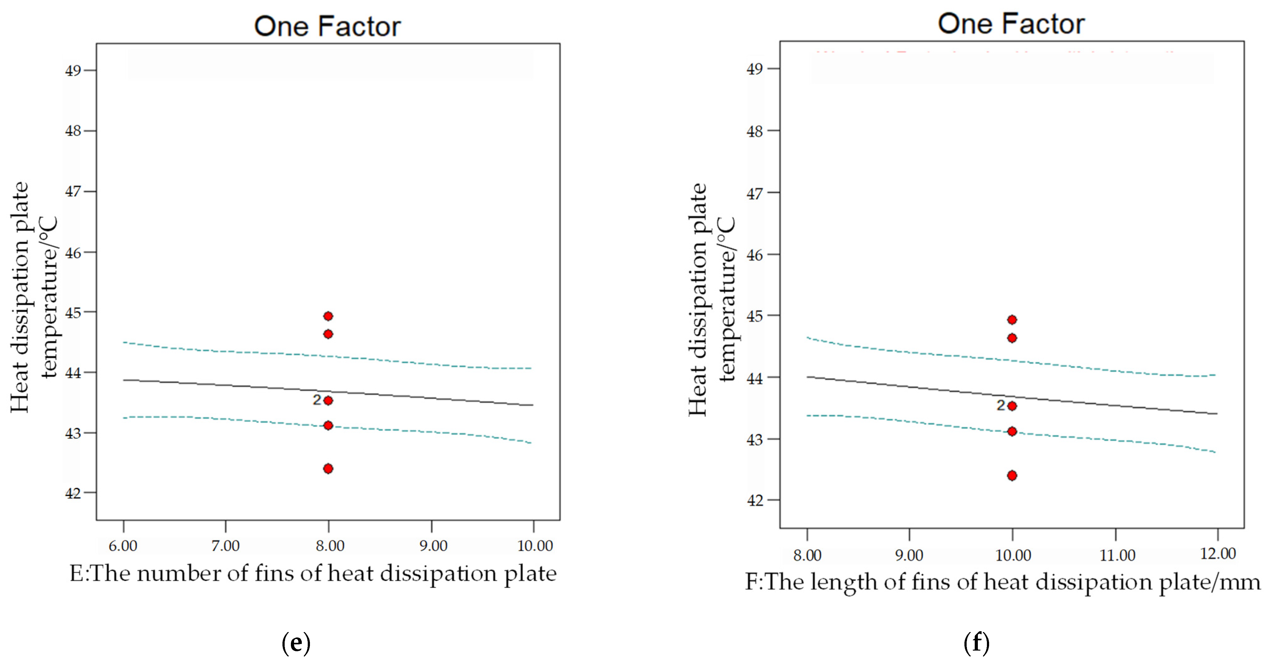
The single factor that affects the temperature change in the heat dissipation plate is shown in Figure 6.
With the increase in single factor A (axial air gap length), the temperature of the heat dissipation plate decreases from about 47 °C to about 43 °C, and then shows a slight upward trend. With the increase in single factor B (input motor speed) and C (the thickness of the permanent magnet in the magnetizing direction), the temperature of the heat dissipation plate gradually rises, with a small increase. With the increase in single factor D (the thickness of the copper plate), the temperature change in the heat dissipation plate is small. With the increase in single factor E (the number of fins of the heat dissipation plate) and F (the length of the fins of the heat dissipation plate), the temperature of the heat dissipation plate gradually decreases, with a small decrease.
In the case of single factor analysis, the percentage of the six factors’ rise and fall that affect the temperature change in the heat dissipation plate is shown in Table 6 below.
It can be observed from the above table that the axial air gap length decreases the most, that is, increasing the axial air gap length to a certain extent allows the temperature of the heat dissipation plate to reach its minimum level, which is closer to the objective function Tmin.

6.3. Two-Factor Analysis

To explain the orthogonal experimental model more intuitively, the three-dimensional graphic analysis of its two-factor influence is carried out by using the software of Design Expert 8.0.6. Figure 7 shows the influence of four groups of representative three-dimensional figures on the temperature of the heat dissipation plate when six factors are combined in pairs.
Figure 7a shows the change in the temperature response surface of the heat dissipation plate at the response point with the influence factors A and B, when the influence factors are as follows: C = 14.70 mm, D = 8.00 mm, E = 8.00 mm and F = 10.00 mm. From the analysis, it can be observed that the larger the value of A, the smaller the value of B and the lower the temperature of the heat dissipation plate, and the influence of AB on the objective function is inversely proportional. When A = 15.00 mm and B = 400 r/min, the temperature of the heat dissipation plate reaches its lowest value, about 42.7 °C. That is, with the increase in the axial air gap length and the decrease in the input motor speed, the temperature of the heat dissipation plate gradually decreases.
Figure 7b shows the change in the temperature response surface of the heat dissipation plate at the response point with the influence factors A and F, when the influence factors are as follows: B = 600 r/min, C = 14.70 mm, D = 8.00 mm and E = 8.00. It can be observed from the analysis that the larger the value of A, the larger the value of F and the lower the temperature of the heat dissipation plate, and the influence of AF on the objective function is proportional. When A = 15.00 mm and F = 12.00 mm, the temperature of the heat dissipation plate reaches its lowest value, about 42.7 °C. That is, with the increase in the axial air gap length and the fin length of the heat dissipation plate, the temperature of the heat dissipation plate gradually decreases.
Figure 7c shows the change in the temperature response surface of the heat dissipation plate at the response point with the influence factors B and E, when the influence factors are as follows: A = 10 mm, C = 14.70 mm, D = 8.00 mm and F = 10.00 mm. It can be observed that the smaller the value of B, the smaller the value of E and the lower the temperature of the heat dissipation plate, and the influence of BE on the objective function is directly proportional. When B = 400 r/min and E = 6, the temperature of the heat dissipation plate reaches its lowest value, about 43.0 °C. That is, with the decrease in the input motor speed, the number of fins of the heat dissipation plate decreases, and the temperature of the heat dissipation plate gradually decreases.
Figure 7d shows the change in the temperature response surface of the heat dissipation plate at the response point with the influence factors E and F, when the influence factors are as follows: A = 10 mm, B = 600 r/min, C = 14.70 mm and D = 8.00 mm. It can be observed that the larger the value of E, the larger the value of F and the lower the temperature of the heat dissipation plate, and the influence of EF on the objective function is proportional. When E = 10 and F = 12 mm, the temperature of the heat dissipation plate reaches its lowest value, about 43 °C. That is, with the increase in the fin number and fin length of the heat dissipation plate, the temperature of the heat dissipation plate gradually decreases.
According to the two-factor influence change diagram of the temperature of the heat dissipation plate, the response and optimization direction of different influence factors can be intuitively expressed.

7. Orthogonal Experiment Optimization

7.1. Simulation Optimal Conditions and Results

In practical problems, in order to ensure better transmission performance and control the cost of the double disk magnetic coupler, the mass of the optimized double disk magnetic coupler should not be higher than 5% of the original mass, and the initial value of the influencing factors is x1 = x2 = x3 = x4 = x5 = x6 = 0, namely x1 = 10, x2 = 600, x3 = 14.7, x4 = 8, x5 = 8 and x6 = 10. The structural parameter optimization model of the double disk magnetic coupler is as follows:
{ min T 1 x 1 , x 2 , x 3 , x 4 , x 5 , x 6 1 m m 0 5 % v v u
Equation (8) is the multi-parameter optimization model established in this paper, with the minimum temperature T of the heat dissipation plate as the objective function and the mass change Δm and average output vu speed as the constraint functions. m0 means the initial mass of the double disk magnetic coupler, Δm indicates the change in its mass during optimization, and vu is the lower limit of the average output speed. The optimal results of the orthogonal experiment are as follows: A = 14.87 mm, B = 501.42 r/min, C = 13.05 mm, D = 6.80 mm, E = 9.85 and F = 11.89 mm. Considering the difficulty of processing technology and the technical limitations of the actual installation of the double disk magnetic coupler experimental device, we calculated the above approximate values. The optimal solution is that the axial air gap length is 15.00 mm, the input motor speed is 500.00 r/min, the thickness of the permanent magnet in the magnetizing direction is 13.00 mm, the thickness of the copper plate is 7.00 mm, and the number of fins of the heat dissipation plate is 10, the length of the fins of the heat dissipation plate is 12.00 mm, and the minimum temperature of the heat dissipation plate is 41.8409 °C.

7.2. Physical Test

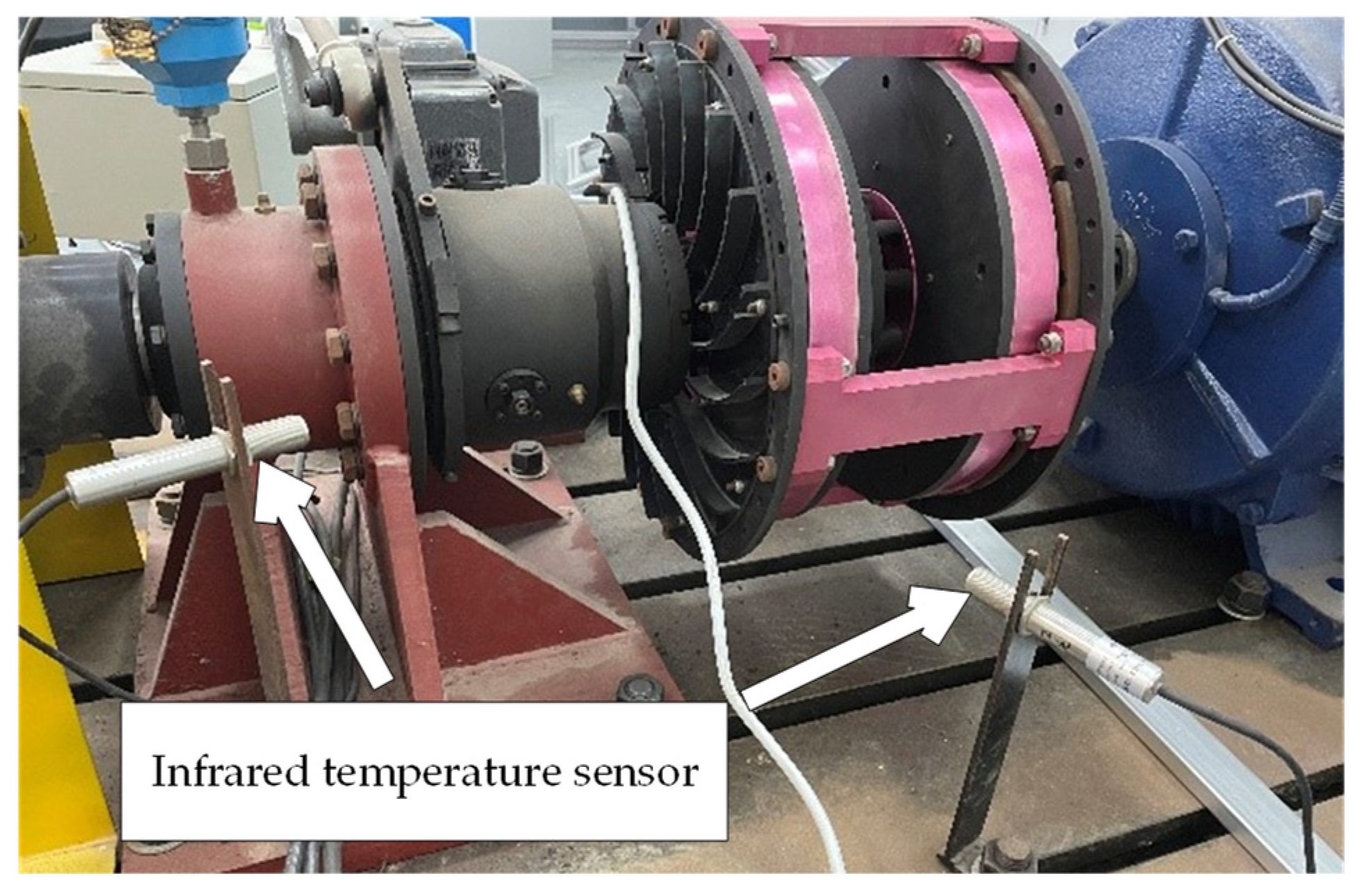
To verify the results of the theoretical analysis and finite element simulation mentioned above, the same parameters as those used in the simulation are selected for physical tests on a double disk magnetic coupler. The field test platform is set up as shown in Figure 8, and the infrared temperature sensor with a heat dissipation structure is shown in Figure 9.
The input motor is a 380 V three-phase low-speed motor, which is controlled by a frequency converter. The rated power of this test-bed is 55 kW, the maximum speed is 3000 r/min, and the recommended speed range is 0–2000 r/min. The measuring circuit is equipped with NCTES3000 torque and a speed measuring instrument (measuring accuracy: 0.2%, measuring range: 500 N.m) and an MIK-2740 temperature inspection instrument, which are connected to a computer to complete signal acquisition and measurement tasks, and Siemens S7-200 series PLC is used for interlocking control.

7.3. Comparison between Simulation and Physical Tests

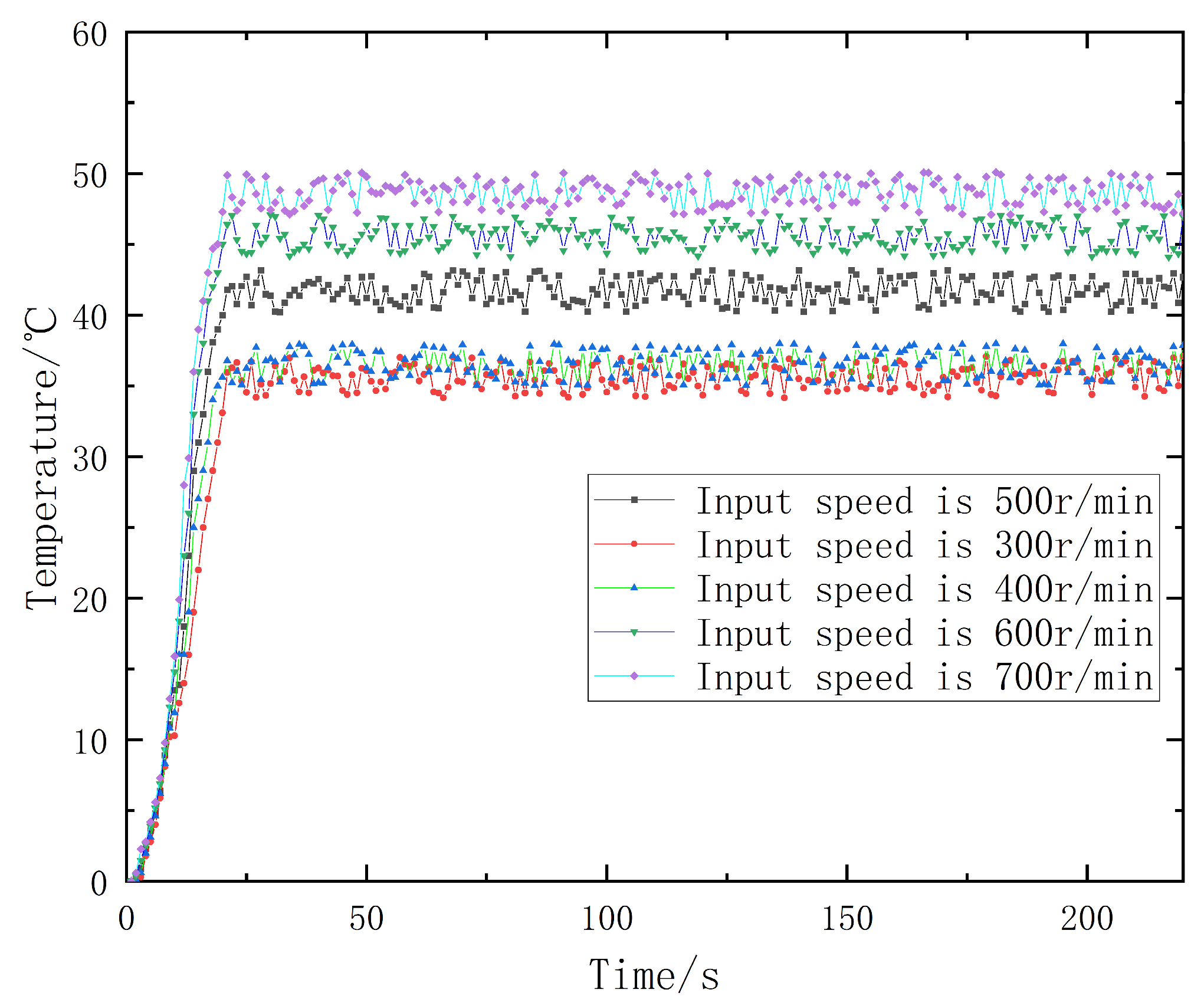
According to the optimization results of the improved response surface method, the experimental time is 225 s, the axial air gap length is 15 mm, the thickness of the permanent magnet in the magnetizing direction is 13.00 mm, the thickness of the copper plate is 8.00 mm, the number of fins of the heat dissipation plate is 10, and the length of the fins of the heat dissipation plate is 12.00 mm, and the input motor speed is changed to 300 r/min, 400 r/min, 500 r/min and 600 r/min in turn. The physical test results are shown in Figure 10. The simulation value is compared with the test value, as shown in Table 7.
It can be observed from Figure 10 that when the double disk magnetic coupler starts up, the temperature of the heat dissipation plate gradually rises, and it reaches a stable running state after 30 s. The five curves in the figure show that the temperature of the heat dissipation plate increases with the increase in the input motor speed. By comparing the simulation results in Table 7 with the physical test results, it can be observed that the simulation results are in good agreement with the physical test results, and the maximum error is 4.8%. The optimal parameter combination obtained after the correction of No.3 in Table 7 is selected, and the error between the simulation result and the physical test result is 1.9%, which indicates that the optimized parameters meet the expected effect of the actual transmission, and can be used to guide the design of the heat dissipation structure of the double disk magnetic coupler in the permanent magnet eddy current drive system of a coal mine.

8. Conclusions

Based on an orthogonal experimental design method, multi-parameter optimization of a heat dissipation structure of a double disk magnetic coupler is carried out, and the temperature of the heat dissipation plate is obtained by the finite element method. The influences of the axial air gap length of the double disk magnetic coupler, the input motor speed, the thickness of the permanent magnet in the magnetizing direction, the thickness of the copper plate, the number of fins of the heat dissipation plate and the length of the fins of the heat dissipation plate on the temperature of the heat dissipation plate are analyzed. Furthermore, the optimal calculation results are selected by the orthogonal experimental design, and the structural parameters of the model are improved and optimized; thus. the heat dissipation performance of the model is improved. The following conclusions are drawn:
  • A six-factor and three-level experiment based on the improved response surface method is designed, and it is found that different variable factors have a certain influence on the heat dissipation effect of the heat dissipation structure model of the double disk magnetic coupler. After analyzing its heat dissipation performance, it can be observed that the order of significant influence from high to low is as follows: axial air gap length > input motor speed > the length of the fins of the heat dissipation plate > the thickness of the permanent magnet in the magnetizing direction > the number of fins of the heat dissipation plate > the thickness of the copper plate. The increase in the axial air gap length can effectively reduce the temperature rise, and the maximum decrease can reach 9.76%, which has an obvious effect. According to the single-factor and double-factor influence change diagram of the temperature of the heat dissipation plate, the response of different influence factors can be intuitively expressed, which is helpful to find the optimal direction of the heat dissipation structure.
  • The parameters of the optimized heat dissipation structure obtained by orthogonal experimental design are as follows: the axial air gap length is 15.00 mm, the input motor speed is 500.00 r/min, the thickness of the permanent magnet in the magnetizing direction is 13.00 mm, the thickness of the copper plate is 7.00 mm, the number of fins of the heat dissipation plate is 10, and the length of the fins of the heat dissipation plate is 12.00 mm. The corresponding value of the objective function, namely the minimum temperature of the heat dissipation plate, is 41.8409 °C. Under this heat dissipation structure, the optimum heat dissipation performance of the double disk magnetic coupler can be achieved.
  • According to the influence law and optimal parameters of the temperature characteristic index of the heat dissipation plate, the physical experiment was designed. The heat dissipation performance of the theoretical and practical heat dissipation structure before and after optimization under actual working conditions was verified. The simulation results are in good agreement with the physical test results, with a maximum error of 4.8%. The error between the simulation results of the optimal parameter combination and the physical test results after correction is only 1.9%, with high accuracy, which verifies the correctness of the numerical model. The research results have reference significance for guiding the optimization of the heat dissipation structure parameters of the double disk magnetic coupler.

Author Contributions

Conceptualization, S.W. and X.M.; methodology, X.M.; software, Z.H.; validation, S.S.; writing—original draft preparation, X.M.; writing—review and editing, X.M.; funding acquisition, S.W. All authors have read and agreed to the published version of the manuscript.

Funding

This research was funded by the National Natural Science Fund Project (Grant No. 52274152), Collaborative Innovation Project of Collaborative Tackling of Universities in Anhui Province (Grant No. GXXT-2020-60); Open Foundation of State Key Laboratory of Mining Response and Disaster Prevention and Control in Deep Coal Mine (Grant No. SKLMRDPC20KF10).

Data Availability Statement

The data that support the findings of this study are available from the corresponding author.

Acknowledgments

The authors thank the Anhui University of Science and Technology for providing financial support for the publication of this research.

Conflicts of Interest

The authors declare no conflict of interest.

References

  1. Florio, F.; Sinha, G.; Sundararaman, R. Designing high-accuracy permanent magnets for low-power magnetic resonance imaging. IEEE Trans. Magn. 2018, 54, 5300209. [Google Scholar] [CrossRef]
  2. Lopez-Alcolea, F.J.; Real, J.V.D.; Roncero-Sanchez, P.; Torres, A.P. Modeling of a Magnetic Coupler Based on Single- and Double-Layered Rectangular Planar Coils With In-Plane Misalignment for Wireless Power Transfer. IEEE Trans. Power Electron. 2020, 35, 5102–5121. [Google Scholar] [CrossRef]
  3. Hogberg, S.; Jensen, B.B.; Bendixen, F.B. Design and Demonstration of a Test-Rig for Static Performance-Studies of Permanent Magnet Couplings. IEEE Trans. Magn. 2013, 49, 5664–5670. [Google Scholar] [CrossRef]
  4. Wolnik, T.; Glinka, T. Axial forces of magnetic pull in a disc type induction motor-experimental test. Prz. Elektrotechniczny 2019, 95, 127–132. [Google Scholar] [CrossRef]
  5. Wang, Y.Q.; Wang, K.F.; Wang, B.L.; Zheng, L.; Zhang, C.W.A. Fracture analysis of superconducting composites with a sandwich structure based on electromagnetic-thermal coupled model. Acta Mech. 2019, 230, 4435–4451. [Google Scholar] [CrossRef]
  6. Bujakiewicz-korońska, R.; Koroński, J. The principle of minimum entropy production for diffusion and heat transfer in open systems. Czas. Techniczne. Nauk. Podstawowe 2011, 108, 23–35. [Google Scholar]
  7. Morrison, A.T. Optimization of heat sink fin geometries for heat sinks in natural convection. In Proceedings of the Conference on Thermal Phenomena in Electronic Systems IEEE, Austin, TX, USA, 5–8 February 1992. [Google Scholar]
  8. Marignetti, F.; Colli, V.D. Thermal Analysis of an Axial Flux Permanent-Magnet Synchronous Machine. IEEE Trans. Magn. 2009, 45, 2970–2975. [Google Scholar] [CrossRef]
  9. Bar-Cohen, A.; Iyengar, M.; Kraus, A.D. Design of Optimum Plate-Fin Natural Convective Heat Sinks. J. Electron. Packag. 2003, 125, 208–216. [Google Scholar] [CrossRef]
  10. Yang, C.J.; Yuan, A.R.; Chen, Z.Q.; Wu, Y.Z.; Zhang, X.F.; Liu, K. Mechanical characteristics and speed regulation characteristics of disk solid asynchronous magnetic coupling. J. Mot. Control. 2019, 23, 9. [Google Scholar]
  11. Wang, L.; Jia, Z.Y.; Zhu, Y.Q.; Liu, H.; Zhang, L. Temperature field of high-power auxiliary cooling magnetic coupling for mining. J. Mech. Eng. 2018, 54, 7. [Google Scholar]
  12. Ge, Y.J.; Zhang, J.; Jiang, H.; Wang, X.; Wan, Z.W. Operation characteristic analysis and heat dissipation structure design of copper sleeve type magnetic coupling. Mech. Transm. 2018, 42, 71–75. [Google Scholar]
  13. Maltseva, V.E.; Andreev, S.V.; Neznakhin, D.S.; Urzhumtsev, A.N.; Selezneva, N.V.; Volegov, A.S. The Magnetic Properties of a NdFeB Permanent Magnets Prepared by Selective Laser Sintering. Phys. Met. Metallogr. 2022, 123, 740–745. [Google Scholar] [CrossRef]
  14. Wang, H.; Monroe, J.G.; Kumari, S.; Leontsev, S.O.; Vasquez, E.S.; Thompson, S.M.; Berg, M.J.; Walters, D.K.; Walters, K.B. Analytical model for electromagnetic induction in pulsating ferrofluid pipe flows. Int. J. Heat Mass Transf. 2021, 175, 121325. [Google Scholar] [CrossRef]
  15. Zhalnin, R.V.; Ladonkina, M.E.; Masyagin, V.F.; Tishkin, V.F. Solution of 3D heat conduction equations using the discontinuous Galerkin method on unstructured grids. J. Samara State Tech. Univ. Ser. Phys. Math. Sci. 2015, 19, 523–533. [Google Scholar]
  16. Roth, G.A.; Aydogan, F. Derivation of new mass, momentum, and energy conservation equations for two-phase flows. Prog. Nucl. Energy 2015, 80, 90–101. [Google Scholar] [CrossRef]
  17. Patil, M.; Muddebihal, A. To Study the Steady State Thermal Analysis of Steam Turbine Casing. Int. J. Innov. Res. Sci. Eng. Technol. 2016, 5, 2347–6710. [Google Scholar]
  18. Han, X.X.; Lin, W.; Qiu, A.; Feng, Z.Q.; Wu, J.M.; Tang, Y.H.; Zhao, C.B. Understanding vortex-induced vibration characteristics of a long flexible marine riser by a bidirectional fluid-structure coupling method. J. Mar. Sci. Technol. 2020, 25, 620–639. [Google Scholar] [CrossRef]
  19. Wang, A.W.; Fan, D.W.; Pan, Y.S.; Zhao, B.Y.; Dai, L.P. Expansion-friction energy-absorbing anti-impact anchor cable and its mechanical characteristics. J. Coal Sci. 2022, 47, 695–710. [Google Scholar]
  20. Liu, B.F.; Li, J.; He, J. Study on hyperspectral remote sensing monitoring and diagnosis model of total phosphorus content in maize leaves. J. Agric. Mach. 2015, 46, 252–258+280. [Google Scholar]
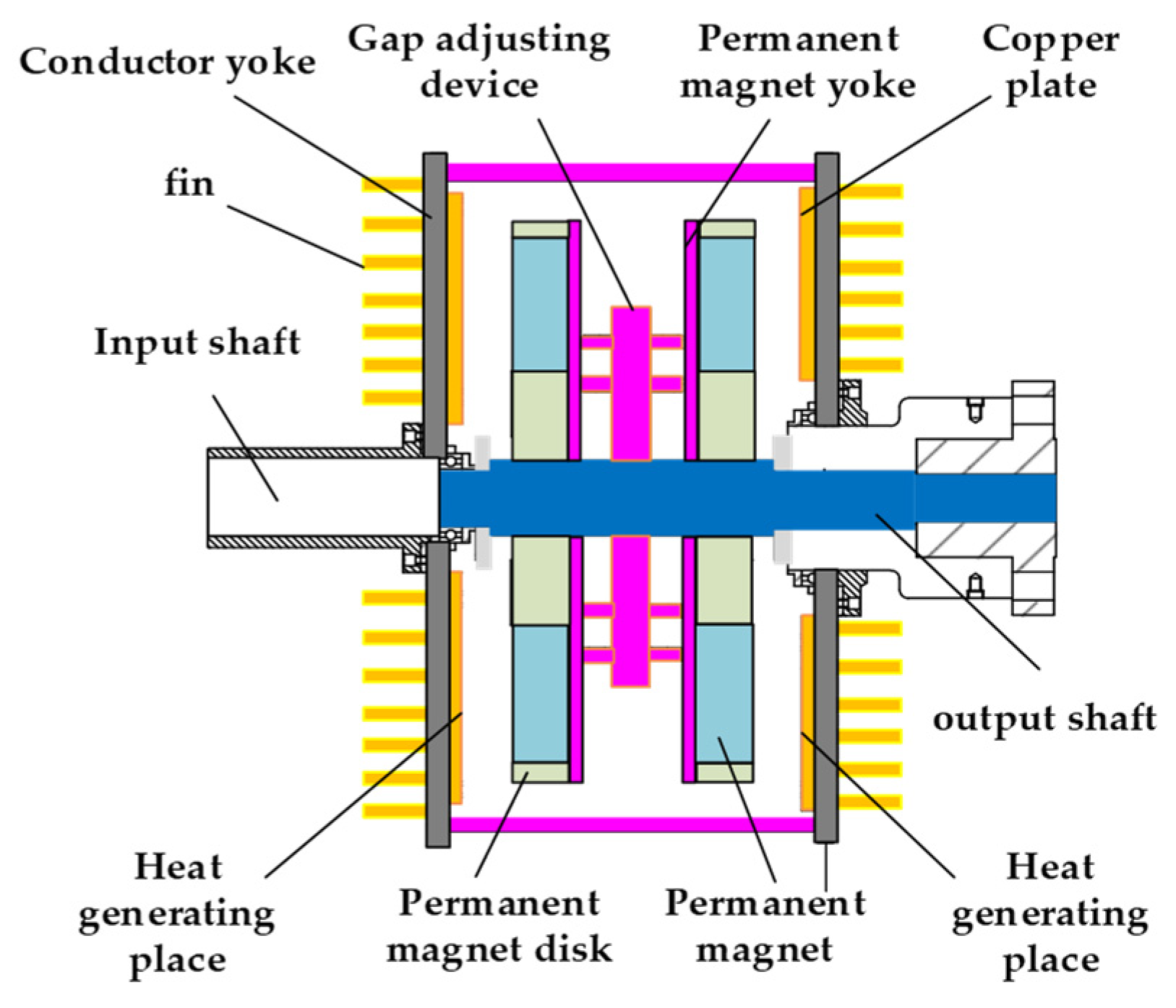
Figure 1. Model of double disk magnetic coupler.
Energies 15 08801 g001
Figure 2. Simplified model.
Energies 15 08801 g002
Figure 3. Three-dimensional model of heat dissipation structure of double disk magnetic coupler.
Energies 15 08801 g003
Figure 4. Meshing diagram.
Energies 15 08801 g004
Figure 5. Simulation diagram of steady-state temperature field of left heat dissipation plate of double disk magnetic coupler. (a) The number of fins of the heat dissipation plate is 6; (b) the number of fins of the heat dissipation plate is 8; (c) the number of fins of the heat dissipation plate is 10; (d) the number of fins of the heat dissipation plate is 12.
Energies 15 08801 g005
Figure 6. Diagram of the single factor that affects the temperature change in the heat dissipation plate. (a) The effect of axial air gap length on the temperature change of heat dissipation plate; (b) The effect of input motor speed on the temperature change of heat dissipation plate; (c) The effect of the thickness of the permanent magnet in the magnetizing direction on the temperature change of heat dissipation plate; (d) The effect of the thickness of the copper plate on the temperature change of heat dissipation plate; (e) The effect of the number of fins of the heat dissipation plate on the temperature change of heat dissipation plate; (f) The effect of the length of the fins of the heat dissipation plate on the temperature change of heat dissipation plate.
Energies 15 08801 g006aEnergies 15 08801 g006b
Figure 7. Diagram of two factors that affect the temperature change in the heat dissipation plate. (a) The change in the temperature response surface of the heat dissipation plate at the response point with the influence factors A and B; (b) The change in the temperature response surface of the heat dissipation plate at the response point with the influence factors A and F; (c) the change in the temperature response surface of the heat dissipation plate at the response point with the influence factors B and E; (d) The change in the temperature response surface of the heat dissipation plate at the response point with the influence factors E and F.
Energies 15 08801 g007
Figure 8. Physical test platform.
Energies 15 08801 g008
Figure 9. Infrared temperature sensor with heat dissipation structure.
Energies 15 08801 g009
Figure 10. Test results of physical experiment.
Energies 15 08801 g010
Table 1. Dimension parameters of components of the double disk magnetic coupler.
NameParameter Value/mm
Length/Outside
Diameter
Width/Inner
Diameter
Thickness
Permanent magnet50.825.412.7
Permanent magnet disk2003012.7
Copper plate200386
Yoke plate2203810
Heat dissipation plate200405
Table 2. Material properties.
NameAttribute
Permanent magnetUH NdFeB, Curie temperature: 150 °C
Permanent magnet diskAluminum
Copper plateCopper
Yoke plateQ235
Heat dissipation plateQ235
Table 3. Response surface test factors and levels.
FactorLevel
−101
Axial air gap length51015
Input motor speed400600800
The thickness of the permanent magnet in the magnetizing direction12.714.716.7
The thickness of the copper plate6810
The number of fins of the heat dissipation plate6810
The length of the fins of the heat dissipation plate81012
Table 4. Simulation results of orthogonal experiment.
Test NumberAxial Air Gap Length
A/mm
Input Motor Speed B/r/minThe Thickness of Permanent Magnet in Magnetizing Direction C/mmThe Thickness of Copper Plate
D/mm
The Number
of Fins of Heat Dissipation Plate
E
The Length
of Fins of Heat Dissipation Plate
F/mm
The Temperature of Heat Dissipation Plate
T/°C
1540014.7681047.121
2540014.788847.231
3540014.7881247.529
4540014.71081047.011
5560012.7861047.301
6560012.78101047.202
7560016.7861047.362
8560016.78101047.688
9580014.7681048.064
10580014.788848.698
11580014.7881246.825
12580014.71081048.273
131040012.7861041.861
141040012.78101043.537
151040016.7861044.251
161040016.78101043.861
171060012.768844.203
181060012.7681243.638
191060012.7108845.014
201060012.71081243.239
211060014.766844.058
221060014.7661243.833
231060014.7610843.754
241060014.76101242.661
251060014.7881044.628
261060014.7881043.524
271060014.7881043.517
281060014.7881042.392
291060014.7881043.107
301060014.7881044.918
311060014.7106844.394
321060014.71061244.172
331060014.71010843.926
341060014.710101243.752
351060016.71081243.964
361060016.7108843.057
371060016.7681243.911
381060016.768845.033
391080012.7861045.664
401080012.78101043.229
411080016.7861045.836
421080016.78101044.837
431540014.7681042.722
441540014.788843.619
451540014.7881242.633
461540014.71081042.814
471560012.7861043.137
481560012.78101042.683
491560016.7861043.562
501560016.78101043.184
511580014.7681043.765
521580014.788843.745
531580014.7881243.326
541580014.71081044.773
Table 5. Error analysis table of an orthogonal experimental model of the temperature of the heat dissipation plate.
ErrorSum of Squares of FluctuationsFreedomMean Square DeviationF-Valuep-ValueSaliency Judgment
Fitting153.90275.7011.85<0.0001Significant
Residual12.51260.48---
Missing term8.04210.380.430.9221Not significant
Table 6. Percentage of increase and decrease for the six factors.
Six FactorsAxial Air
Gap Length
Input Motor SpeedThe Thickness of Permanent Magnet in Magnetizing DirectionThe Thickness of Copper PlateThe Number
of Fins of Heat
Dissipation Plate
The Length of Fins of Heat Dissipation Plate
The amplitude of the increase0.23%2.30%0.92%0.46%--
The amplitude of the reduction9.76%--0.23%0.92%1.15%
Table 7. Orthogonal experimental design scheme and simulation and physical test results.
Serial NumberAxial Air
Gap Length (mm)
Input Motor Speed (r/min)The Thickness of Permanent Magnet in Magnetizing Direction (mm)The Thickness of Copper Plate (mm)The Number of Fins of Heat Dissipation PlateThe Length
of Fins of
Heat Dissipation Plate (mm)
Simulation ResultsPhysical Test ResultsError
Heat Dissipation Plate Temperature
(°C)
Heat Dissipation Plate Temperature
(°C)
115300138101235.136.84.8%
215400138101236.738.03.5%
315500138101241.842.61.9%
415600138101245.447.34.2%
515700138101248.649.51.8%
Publisher’s Note: MDPI stays neutral with regard to jurisdictional claims in published maps and institutional affiliations.